Operation Manual - wire-wizard.com · by ELCo Enterprises), along with an ELCo supplied Filter/...
16
ENTERPRISES, INC. Models EL-NCS-A-16-D & EL-NCS-AC-16-D Ship Date Serial # ELCo, Inc. • 5750 Marathon Drive • Jackson, MI 49201 • (517) 782-8040 • Fax: (517) 782-8039 www.wire-wizard.com Operation Manual Installation, Maintenance & Warranty Information
Transcript of Operation Manual - wire-wizard.com · by ELCo Enterprises), along with an ELCo supplied Filter/...

ENTERPRISES, INC.
Models EL-NCS-A-16-D & EL-NCS-AC-16-D
Ship Date Serial #
ELCo, Inc. • 5750 Marathon Drive • Jackson, MI 49201 • (517) 782-8040 • Fax: (517) 782-8039www.wire-wizard.com
OperationManualInstallation, Maintenance &Warranty Information

2Rev. 10/18/16
1.0 INTRODUCTION ...............................................................................................................................31.1 Warranty ............................................................................................................................................31.2 Model Information ..............................................................................................................................31.3 Safety ................................................................................................................................................4
2.0 INSTALLATION .................................................................................................................................42.1 Mounting the Torch Wizard ................................................................................................................52.2 Pneumatic Connection ......................................................................................................................52.3 Electrical Connection .........................................................................................................................52.4 Adjusting V-Block ...............................................................................................................................62.5 Reamer Adjustment ...........................................................................................................................72.6 Anti-Spatter Dispensing .....................................................................................................................8
3.0 MAINTENANCE OF REAMER & WIRE CUTTER ............................................................................9
4.0 ELECTRICAL SCHEMATIC & SEQUENCE OF OPERATIONS ....................................................10
5.0 PNEUMATIC SCHEMATIC .............................................................................................................11
6.0 EXPLODED VIEW w/BOM ....................................................................................................... 12-136.1 Parts List..........................................................................................................................................13
7.0 OPTIONAL EQUIPMENT, REAMER BLADES & ACCESSORIES .......................................... 14-15
TABLE OF CONTENTS
3Rev. 10/18/16
This guide is designed to assist the user whose primary responsibility is to maintain and operate the Torch Wizard Nozzle Cleaning Station. This manual provides specific information on installation, safety, basic operation, and maintenance. Please read, understand and follow all safety procedures.
The Torch Wizard EL-NCS-AC-16-D and EL-NCS-A-16-D models offer fast and efficient cleaning cycle times and high production rates. The anti-spatter solution is applied via venturi style sprayers on the front of the reamer.
The complete sequence of the Torch Wizard Nozzle Cleaning Station must be started and controlled by a robot controller, programmable logic controller (PLC), or some other superior control system. See sequence of operations on page 9 for details.
In order to obtain the optimum cleaning performance, the interior of the nozzle should be sprayed with Blue Magic® or Blue Chill® Anti-Spatter after cleaning.
1.0 INTRODUCTION
1.1 WARRANTY
1.2 MODEL INFORMATIONModel EL-NCS-AC-16-D • Base Unit • Integrated Venturi Style Anti-spatter Sprayers • Wire Cutter
Model EL-NCS-A-16-D • Base Unit • Integrated Venturi Style Anti-spatter Sprayers • No Wire Cutter (may be added later if desired)
TWO YEAR EXTENDED WARRANTY TERMS AND CONDITIONS: ELCo Enterprises, Inc. (hereinafter “ELCo”) shall warrant the Torch Wizard Nozzle Cleaning Station (hereinafter “Torch Wizard”) to be free of defects in material and/or workmanship for Two (2) Years from the date of shipment to the Buyer. This two year warranty requires the exclusive use of Blue Magic® or Blue Chill® anti-spatter (or other anti-spatter supplied by ELCo Enterprises), along with an ELCo supplied Filter/Regulator/Lubricator (FRL) with auto-drain. The warranty shall cover 100% of all parts and labor with the exception of misuse, abuse, neglect and typical consumables as determined by ELCo. Failure to follow proper installation and mainte-nance procedures specified in this operation manual will void this warranty. ELCo will, at its option, repair, replace or issue a credit for the value of the defective Torch Wizard. The use of anti-spatter agents other than Blue Magic® or Blue Chill® and non-ELCo parts and/or consumables with the Torch Wizard may damage or limit the performance of the Torch Wizard and will void this extended warranty on all components.
ONE YEAR LIMITED WARRANTY TERMS AND CONDITIONS: For units using anti-spatter agents other than Blue Magic® or Blue Chill®, ELCo Enterprises, Inc. shall warrant the Torch Wizard Nozzle Cleaning Station to be free of defects in material and/or workmanship for One (1) Year from the date of shipment to the Buyer. The warranty shall cover 100% of all parts and labor with the exception of misuse, abuse, neglect and typical consumables as determined by ELCo. This limited warranty excludes all sprayer components, which are warranted to be
free from defects and/or workmanship for 90 days from the date of shipment to the buyer. Failure to follow proper installation and maintenance procedures specified in this operation manual will void this warranty. This includes the use of a Filter/Regulator/Lubricator (FRL) without auto-drain func-tionality. ELCo will, at its option, repair, replace or issue a cred-it for the value of the defective Torch Wizard.
Buyer accepts all responsibility for compliance with any/all Local, State and Federal Laws or Regulations including Regu-lations of Foreign Governments.
No equipment shall be returned to ELCo without a Return Authorization Number from ELCo. Upon evaluation and deter-mination of warranty, replacements or repairs will be sent to the Buyer. If a replacement is needed immediately, a purchase order is required to cover the cost of the product until the warranty is determined.
ELCo’s warranty is limited to replacing any goods that are proved to be defective and ELCo in no event shall have any liability for paying incidental or consequential damages includ-ing and without limitation, damages resulting in personal or bodily injury or death, or damages to, or loss of use of any property. Notwithstanding any of these terms and conditions, the warranties set forth shall apply in connection with any sales of goods, services or design by ELCo and are in lieu of all other warranties, express or implied, including warranties of merchantability and fitness for a particular purpose.

4Rev. 10/18/16
1. Do not remove or deface any labels that are attached to the unit.
2. Ensure that all equipment in the area is disabled and locked out prior to entering the work zone where the Torch Wizard is located.
3. Ensure that all electrical and air power is discon-nected prior to performing any maintenance on the Torch Wizard.
4. Keep hands and face away from clamp, reamer and spray operating space during both automatic and manual operation.
5. Ensure that all electrical and pneumatic connections comply with the codes relevant to the country and/or state where the Torch Wizard is installed.
6. Do not exceed the specified operating air pressure.7. Ensure that there is no equipment (e.g. robot) in the
Torch Wizard prior to shutting down the system.8. Additional safety information can be found at the
following websites: http://www.osha-slc.gov/SLTC/robotics/index.html http://www.ansi.org http://www.nfpa.org
1.3 SAFETYThe Torch Wizard Nozzle Cleaning Station is designed to be safe to operate, provided the user reads, understands and adheres to the safety precautions listed below. Failure to adhere to these precautions may result in personal injury and/or damage to the equipment.
2.0 INSTALLATION
Figure 1: Torch Wizard Components with Anti-spatter Spray System (EL-NCS-A-16-D shown)
Anti-spatter ReservoirOptional Wire Cutter
Location
Test CycleButton
Reed Switch Access Panel
Reamer Blade
Mounting Location for optional
Tool Center Point
Motor
Lubricated & Filtered Air InElectrical
Connection(5 pin) Catch
Tray
Anti-spatter Sprayers (2)

5Rev. 10/18/16
Select a location within the robotic workcell that provides the robot with the shortest approach points. It is important to consider the robot work envelope and any fixed obstructions or potential interference.
• Mount the Torch Wizard to a stable platform that is parallel to the floor for best results (an optional stand is available). Use the (4) 11/32 mounting holes provided on base of the Torch Wizard to secure the unit to the platform.
• It is recommended that (4) M8 – 1.25 SHCS (Socket Head Cap Screws) are used to mount the Torch Wizard to the platform (the optional stand provides M8 – 1.25 tapped holes for mounting).
2.1 MOUNTING THE TORCH WIZARD
BOLT PATTERN (same for all models)
We recommend “Push-to Lock” style fittings on the Torch Wizard for supplying air to the unit. Use an air line with a 5/16” outside diameter to supply air to the Torch Wizard. There is just one location that supplies air to the unit. (Refer to figure 3 at left).
2.2 PNEUMATIC CONNECTION
Air Supply Requirements: Air must be filtered & regulated with a Filter/Regulator/Lubricator & LUBRICATED. • Use an AIR SUPPLY LINE with an inside diameter of 3/8”, connect to the 1/4” N.P.T. female inlet located on the side of the Reamer.
• 80 psi recommended at 16 cfm (5.0-7.0 BAR at 450 lpm) at the Reamer during operation.
• LUBRICATOR ADJUSTMENT: Set the lubricator to deliver one drop of pneumatic oil for every two minutes of operation. DO NOT OVER-LUBRICATE.
Use of unfiltered, dirty air may result in damage to the unit and will void the warranty.
2.3 ELECTRICAL CONNECTIONThe complete sequence of the Torch Wizard Nozzle Cleaning Station must be started and controlled by a robot controller, programmable logic controller (PLC), or other superior control system.
Electrical Draw: 0.5 AmpsSee Electrical Schematic on page 10 for detailed wiring information.
Figure 3
Figure 2
6Rev. 10/18/16
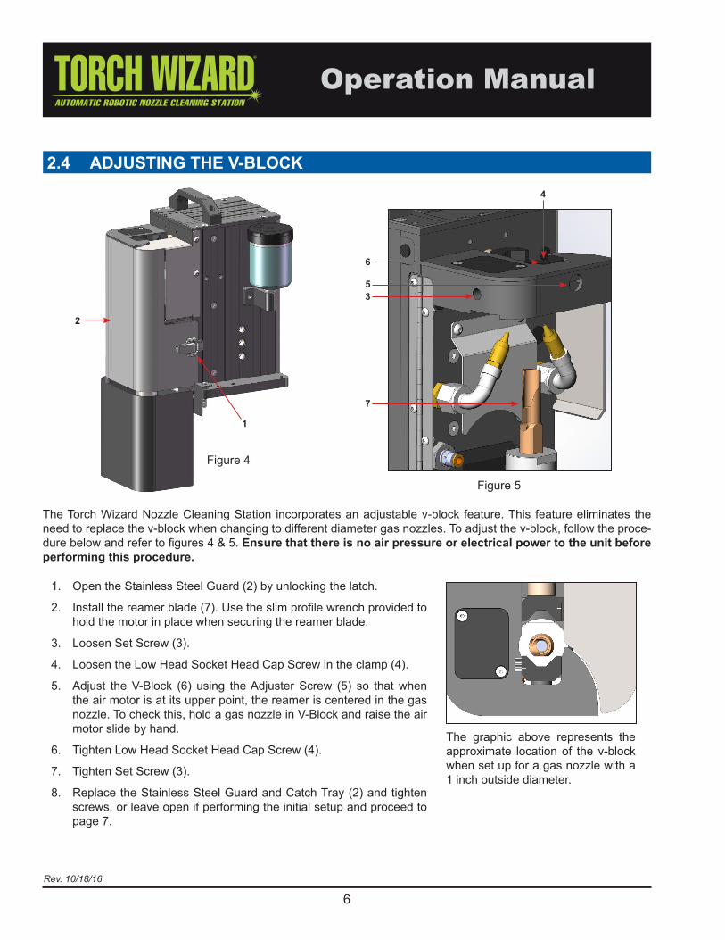
2.4 ADJUSTING THE V-BLOCK
1. Open the Stainless Steel Guard (2) by unlocking the latch.
2. Install the reamer blade (7). Use the slim profile wrench provided to hold the motor in place when securing the reamer blade.
3. Loosen Set Screw (3).
4. Loosen the Low Head Socket Head Cap Screw in the clamp (4).
5. Adjust the V-Block (6) using the Adjuster Screw (5) so that when the air motor is at its upper point, the reamer is centered in the gas nozzle. To check this, hold a gas nozzle in V-Block and raise the air motor slide by hand.
6. Tighten Low Head Socket Head Cap Screw (4).
7. Tighten Set Screw (3).
8. Replace the Stainless Steel Guard and Catch Tray (2) and tighten screws, or leave open if performing the initial setup and proceed to page 7.
The Torch Wizard Nozzle Cleaning Station incorporates an adjustable v-block feature. This feature eliminates the need to replace the v-block when changing to different diameter gas nozzles. To adjust the v-block, follow the proce-dure below and refer to figures 4 & 5. Ensure that there is no air pressure or electrical power to the unit before performing this procedure.
The graphic above represents the approximate location of the v-block when set up for a gas nozzle with a 1 inch outside diameter.
Figure 5
2
1
6
53
4
Figure 4
7

7Rev. 10/18/16
In order to ensure adequate cleaning of the gas nozzle, it is essential that the correct reamer insertion depth is obtained.
The reamer insertion depth will vary based upon the nozzle, tip and diffuser on the torch. In general, the reamer can be insert-ed up until it is approximately 1/16” to 1/8” away from making contact with the diffuser (see example in Fig. 6-B). Removing the nozzle from the torch to ensure the proper depth and clear-ance from the diffuser is recommended. It is imperative that the reamer not make contact with the gas diffuser as this will cause damage to both the reamer and the gas diffuser. The Torch Wizard is not designed to clean the contact tip or gas diffuser.
To adjust the reamer depth, use the following procedure and refer to Figure 6: (Ensure that there is no air pressure or elec-trical power to the unit before performing this procedure)
1. Remove the Stainless Steel Guard. (refer to figure 4 and the procedure for adjusting the V-Block on pg 6).
2. With one hand, hold a gas nozzle in the V-Block at the posi-tion that will be used when programming the robot. With the other hand, raise the reamer and check the insertion depth of the reamer bit (1).
3. If the insertion depth is incorrect, loosen the Socket Head Cap Screws (2). Move the Air Motor (3) up or down to obtain the correct insertion depth. If the motor will not move, screw in the Jack Screws (4) to loosen the motor clamp.
4. Back out the Jack Screws (4) if necessary, and tighten the Socket Head Cap Screws (2). Repeat steps 1-3 until the correct insertion depth is obtained.
2.5 REAMER ADJUSTMENT
Figure 6
1
2
3 4
Note: The air motor on this reaming station has a max torque of 7.3 ft/lbs @ 90 psi at the motor.
POSITIONING ROBOTThe robot must be positioned such that the O.D. of the nozzle rests evenly against the V-Block. Failure to program the robot so that the nozzle rests against the v-block could result damage to the robot due to reactionary forces trans-mitted to the robot axes when the nozzle is clamped with the air cylinder.
See page 10 for the electrical schematic for your Torch Wizard model.
WARNING: Ensure that the adjustable v-block and the air motor have been correctly set prior to positioning the robot and running the Torch Wizard in the automatic mode. Refer to sections 2.4 Adjusting V-Block and 2.5 Adjusting Air Motor. Failure to adjust these two items properly will result in damage to Torch Wizard and possibly the Robot.
1/16”-1/8” (1.6-3.2mm)between top of blade &
contact point on diffuser
Figure 6-BExample of typical reamer insertion depth. End of blade should be approx. 1/16”-1/8” from the contact point on the diffuser. This location will vary based on the torch design.
8Rev. 10/18/16
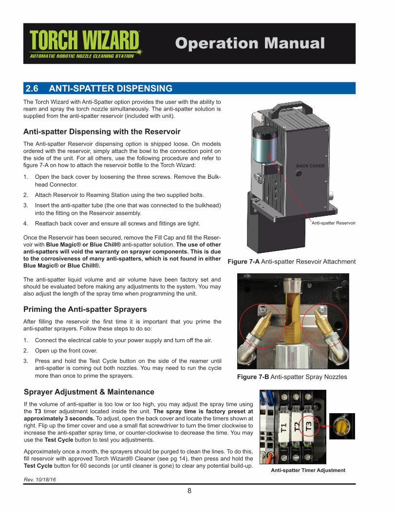
2.6 ANTI-SPATTER DISPENSINGThe Torch Wizard with Anti-Spatter option provides the user with the ability to ream and spray the torch nozzle simultaneously. The anti-spatter solution is supplied from the anti-spatter reservoir (included with unit).
Anti-spatter Dispensing with the ReservoirThe Anti-spatter Reservoir dispensing option is shipped loose. On models ordered with the reservoir, simply attach the bowl to the connection point on the side of the unit. For all others, use the following procedure and refer to figure 7-A on how to attach the reservoir bottle to the Torch Wizard:
1. Open the back cover by loosening the three screws. Remove the Bulk-head Connector.
2. Attach Reservoir to Reaming Station using the two supplied bolts.
3. Insert the anti-spatter tube (the one that was connected to the bulkhead) into the fitting on the Reservoir assembly.
4. Reattach back cover and ensure all screws and fittings are tight.
Once the Reservoir has been secured, remove the Fill Cap and fill the Reser-voir with Blue Magic® or Blue Chill® anti-spatter solution. The use of other anti-spatters will void the warranty on sprayer components. This is due to the corrosiveness of many anti-spatters, which is not found in either Blue Magic® or Blue Chill®.
The anti-spatter liquid volume and air volume have been factory set and should be evaluated before making any adjustments to the system. You may also adjust the length of the spray time when programming the unit.
Priming the Anti-spatter SprayersAfter filling the reservoir the first time it is important that you prime the anti-spatter sprayers. Follow these steps to do so:
1. Connect the electrical cable to your power supply and turn off the air.
2. Open up the front cover.
3. Press and hold the Test Cycle button on the side of the reamer until anti-spatter is coming out both nozzles. You may need to run the cycle more than once to prime the sprayers.
BACK COVER
Anti-spatter Reservoir
Figure 7-B Anti-spatter Spray Nozzles
Anti-spatter Timer Adjustment
Sprayer Adjustment & MaintenanceIf the volume of anti-spatter is too low or too high, you may adjust the spray time using the T3 timer adjustment located inside the unit. The spray time is factory preset at approximately 3 seconds. To adjust, open the back cover and locate the timers shown at right. Flip up the timer cover and use a small flat screwdriver to turn the timer clockwise to increase the anti-spatter spray time, or counter-clockwise to decrease the time. You may use the Test Cycle button to test you adjustments.
Approximately once a month, the sprayers should be purged to clean the lines. To do this, fill reservoir with approved Torch Wizard® Cleaner (see pg 14), then press and hold the Test Cycle button for 60 seconds (or until cleaner is gone) to clear any potential build-up.
Figure 7-A Anti-spatter Resevoir Attachment
9Rev. 10/18/16
The Torch Wizard is for the most part, a low maintenance peripheral. However, maintenance of this unit should still be added to your preventive maintenance schedule. The following should be checked at regular intervals:
• Clean anti-spatter lines monthly (see pg. 8)
• Visually inspect unit for damage, especially mechanically stressed components
• Clean the filter
• Check that the air lines are free of leaks
• Clean anti-spatter hole in reamer blade
3.0 MAINTENANCE OF CLEANING STATION & WIRE CUTTER
• Ensure the lubricator has lubricant and fill if necessary
• Check blade for chips or cracks, replace if necessary
• Check for lose parts
• Ensure the proper depth of blade in the nozzle
• Ensure the blade is not making contact with the diffuser
• Ensure all covers are in place before operating
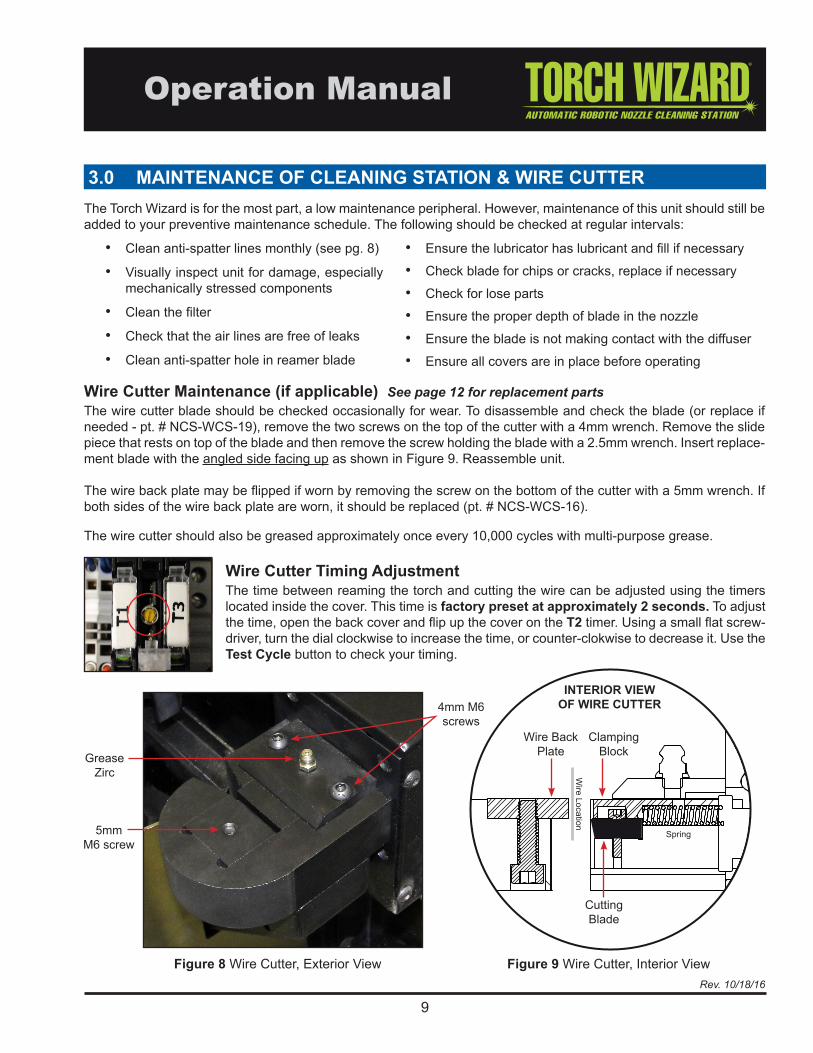
Wire Cutter Maintenance (if applicable) See page 12 for replacement partsThe wire cutter blade should be checked occasionally for wear. To disassemble and check the blade (or replace if needed - pt. # NCS-WCS-19), remove the two screws on the top of the cutter with a 4mm wrench. Remove the slide piece that rests on top of the blade and then remove the screw holding the blade with a 2.5mm wrench. Insert replace-ment blade with the angled side facing up as shown in Figure 9. Reassemble unit.
The wire back plate may be flipped if worn by removing the screw on the bottom of the cutter with a 5mm wrench. If both sides of the wire back plate are worn, it should be replaced (pt. # NCS-WCS-16).
The wire cutter should also be greased approximately once every 10,000 cycles with multi-purpose grease.
Wire Cutter Timing AdjustmentThe time between reaming the torch and cutting the wire can be adjusted using the timers located inside the cover. This time is factory preset at approximately 2 seconds. To adjust the time, open the back cover and flip up the cover on the T2 timer. Using a small flat screw-driver, turn the dial clockwise to increase the time, or counter-clokwise to decrease it. Use the Test Cycle button to check your timing.
4mm M6 screws
GreaseZirc
5mmM6 screw
Wire Back Plate
Cutting Blade
INTERIOR VIEW OF WIRE CUTTER
Figure 8 Wire Cutter, Exterior View Figure 9 Wire Cutter, Interior View
Wire Location
Spring
Clamping Block
10Rev. 10/18/16
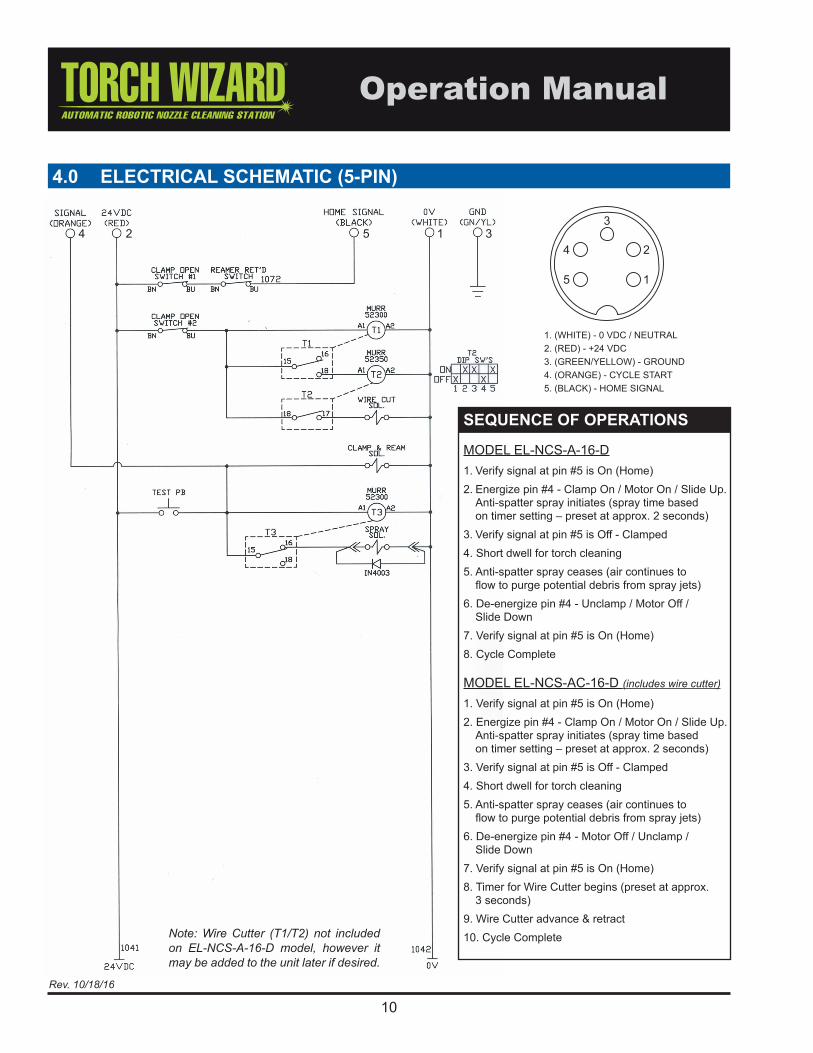
4.0 ELECTRICAL SCHEMATIC (5-PIN)
Note: Wire Cutter (T1/T2) not included on EL-NCS-A-16-D model, however it may be added to the unit later if desired.
SEQUENCE OF OPERATIONS
MODEL EL-NCS-A-16-D1. Verify signal at pin #5 is On (Home)2. Energize pin #4 - Clamp On / Motor On / Slide Up. Anti-spatter spray initiates (spray time based on timer setting – preset at approx. 2 seconds)3. Verify signal at pin #5 is Off - Clamped4. Short dwell for torch cleaning5. Anti-spatter spray ceases (air continues to flow to purge potential debris from spray jets)6. De-energize pin #4 - Unclamp / Motor Off / Slide Down7. Verify signal at pin #5 is On (Home)8. Cycle Complete
MODEL EL-NCS-AC-16-D (includes wire cutter)
1. Verify signal at pin #5 is On (Home)2. Energize pin #4 - Clamp On / Motor On / Slide Up. Anti-spatter spray initiates (spray time based on timer setting – preset at approx. 2 seconds)3. Verify signal at pin #5 is Off - Clamped4. Short dwell for torch cleaning5. Anti-spatter spray ceases (air continues to flow to purge potential debris from spray jets)6. De-energize pin #4 - Motor Off / Unclamp / Slide Down7. Verify signal at pin #5 is On (Home)8. Timer for Wire Cutter begins (preset at approx. 3 seconds)9. Wire Cutter advance & retract10. Cycle Complete
1. (WHITE) - 0 VDC / NEUTRAL2. (RED) - +24 VDC3. (GREEN/YELLOW) - GROUND4. (ORANGE) - CYCLE START5. (BLACK) - HOME SIGNAL
524 1 3

11Rev. 10/18/16
5.0 PNEUMATIC SCHEMATIC
12Rev. 10/18/16
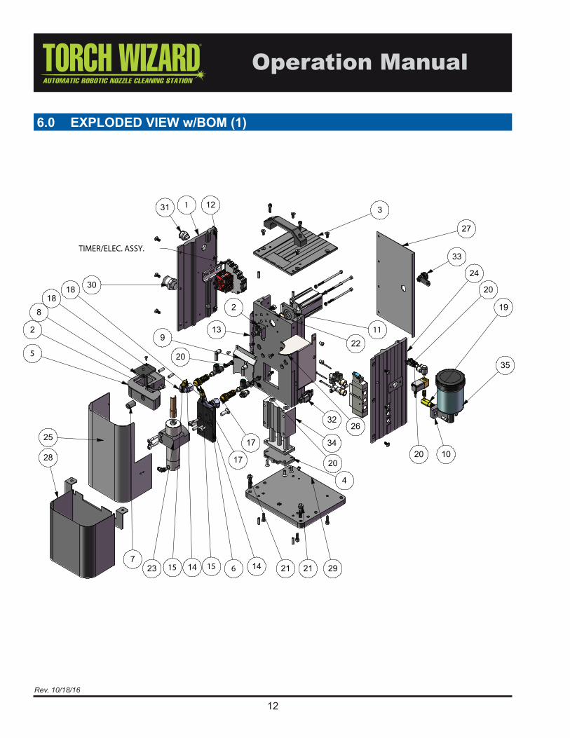
6.0 EXPLODED VIEW w/BOM (1)
13Rev. 10/18/16
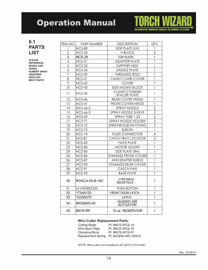
6.1PARTSLIST
NOTE: Wire cutter not included on EL-NCS-A-16 model
PLEASE REFERENCE MODEL AND SERIAL NUMBER WHEN ORDERING REPLACE-MENT PARTS
Wire Cutter Replacement Parts:Cutting Blade Pt. #NCS-WCS-19Wire Back Plate Pt. #NCS-WCS-16Clamping Block Pt. #NCS-WCS-07Replacement Spring Pt. #C0240-045-1000-S
ITEM NO. PART NUMBER DESCRIPTION QTY.1 NCS-88 SIDE PLATE (LH) 12 NCS-24 V-BLOCK 2
TOP PLATE 14 NCS-31 ADAPTER PLATE 15 NCS-32 SUPPORT NEST 16 NCS-34 SADDLE PLATE 17 NCS-39 THREADED ROD 18 NCS-41 CANDY CANE COVER 19 NCS-42 COVER 110 NCS-43 SIDE MOUNT BLOCK 1
11 NCS-45 CLAMP CYLINDER SPACER PLATE 1
12 NCS-46 REAR COVER HINGE 113 NCS-47 FRONT COVER HINGE 114 NCS-66-2 SPRAY NOZZLE 215 NCS-66-3 SPRAY NOZZLE SLEEVE 216 NCS-69 SPRAY TUBE 1.25 217 NCS-71 SPRAY NOZZLE HOLDER 218 NCS-72 SPRAYER ELBOW FITTING 219 NCS-73 ELBOW 120 NCS-74 FLUID CONNECTOR 421 NCS-81 CATCH TRAY LOCATOR 222 NCS-83 FACE PLATE 123 NCS-84 MOTOR MOUNT 124 NCS-85 SIDE PLATE (RH) 125 NCS-86 STAINLESS FRONT COVER 126 NCS-87 ANTI-SPATTER SHIELD 127 NCS-90 STAINLESS REAR COVER 128 NCS-91 CATCH PAN 129 NCS-93 BASE PLATE 1
5 PIN MALE RECEPTICLE 1
31 ULV4F2BSS335 PUSH BUTTON 1FRONT DOOR LATCH 1
LATCH 1
1
1
14Rev. 10/18/16
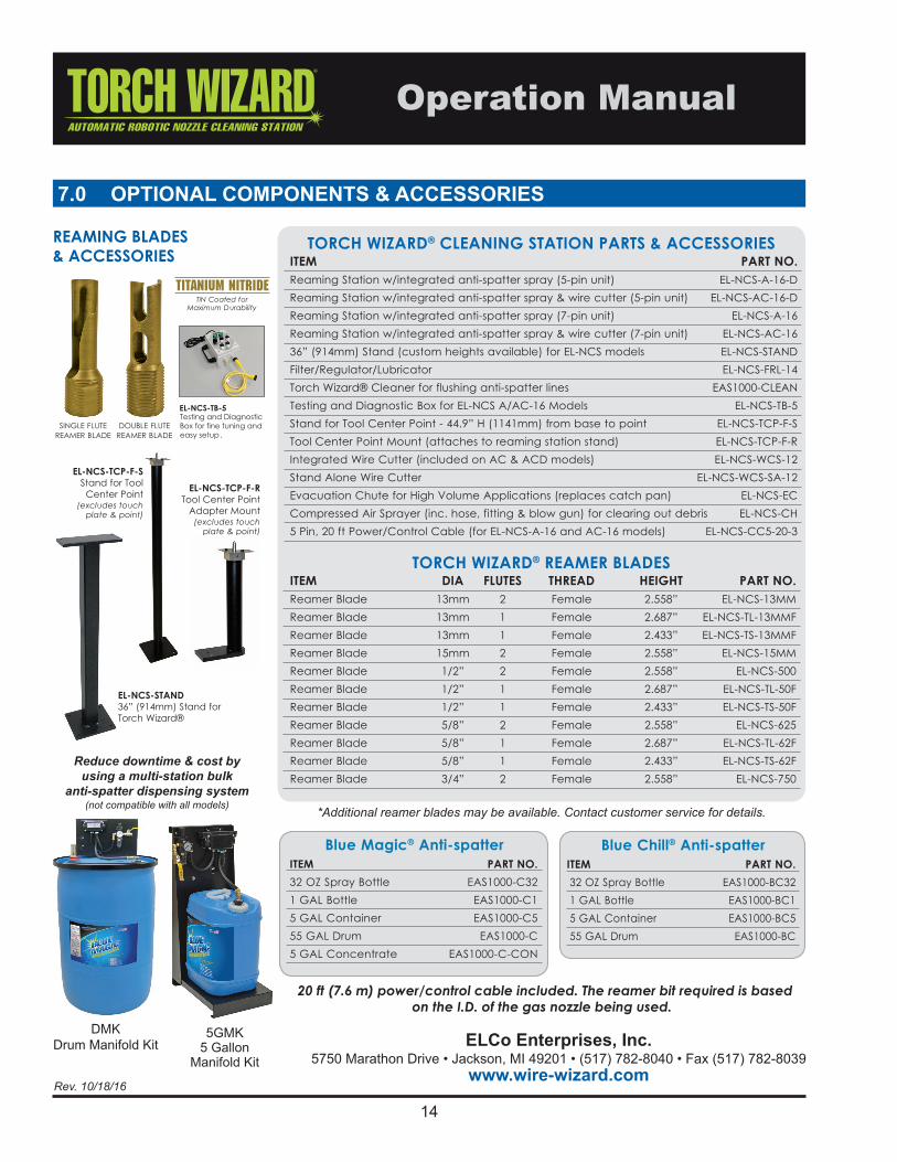
7.0 OPTIONAL COMPONENTS & ACCESSORIES
DMKDrum Manifold Kit
5GMK5 Gallon
Manifold KitELCo Enterprises, Inc.
5750 Marathon Drive • Jackson, MI 49201 • (517) 782-8040 • Fax (517) 782-8039www.wire-wizard.com
Blue Magic® Anti-spatter
ITEM PART NO. 32 OZ Spray Bottle EAS1000-C32 1 GAL Bottle EAS1000-C1 5 GAL Container EAS1000-C5 55 GAL Drum EAS1000-C 5 GAL Concentrate EAS1000-C-CON
Blue Chill® Anti-spatter
ITEM PART NO. 32 OZ Spray Bottle EAS1000-BC32 1 GAL Bottle EAS1000-BC1 5 GAL Container EAS1000-BC5 55 GAL Drum EAS1000-BC
Reduce downtime & cost by using a multi-station bulk
anti-spatter dispensing system(not compatible with all models)
SINGLE FLUTE REAMER BLADE
DOUBLE FLUTE Testing and DiagnosticBox for fine tuning andeasy setup.REAMER BLADE
TiN Coated for Maximum Durability
REAMING BLADES & ACCESSORIES
*Additional reamer blades may be available. Contact customer service for details.
EL-NCS-STAND 36” (914mm) Stand forTorch Wizard®
EL-NCS-TCP-F-R Tool Center Point
Adapter Mount(excludes touch
plate & point)
EL-NCS-TCP-F-S Stand for Tool
Center Point(excludes touch
plate & point)
ITEM DIA FLUTES THREAD HEIGHT PART NO. Reamer Blade 13mm 2 Female 2.558” EL-NCS-13MM Reamer Blade 13mm 1 Female 2.687” EL-NCS-TL-13MMF Reamer Blade 13mm 1 Female 2.433” EL-NCS-TS-13MMF Reamer Blade 15mm 2 Female 2.558” EL-NCS-15MM Reamer Blade 1/2” 2 Female 2.558” EL-NCS-500 Reamer Blade 1/2” 1 Female 2.687” EL-NCS-TL-50F Reamer Blade 1/2” 1 Female 2.433” EL-NCS-TS-50F Reamer Blade 5/8” 2 Female 2.558” EL-NCS-625 Reamer Blade 5/8” 1 Female 2.687” EL-NCS-TL-62F Reamer Blade 5/8” 1 Female 2.433” EL-NCS-TS-62F Reamer Blade 3/4” 2 Female 2.558” EL-NCS-750
ITEM PART NO. Reaming Station w/integrated anti-spatter spray (5-pin unit) EL-NCS-A-16-D Reaming Station w/integrated anti-spatter spray & wire cutter (5-pin unit) EL-NCS-AC-16-D Reaming Station w/integrated anti-spatter spray (7-pin unit) EL-NCS-A-16 Reaming Station w/integrated anti-spatter spray & wire cutter (7-pin unit) EL-NCS-AC-16 36” (914mm) Stand (custom heights available) for EL-NCS models EL-NCS-STAND Filter/Regulator/Lubricator EL-NCS-FRL-14 Torch Wizard® Cleaner for flushing anti-spatter lines EAS1000-CLEAN Testing and Diagnostic Box for EL-NCS A/AC-16 Models EL-NCS-TB-5 Stand for Tool Center Point - 44.9” H (1141mm) from base to point EL-NCS-TCP-F-S Tool Center Point Mount (attaches to reaming station stand) EL-NCS-TCP-F-R Integrated Wire Cutter (included on AC & ACD models) EL-NCS-WCS-12 Stand Alone Wire Cutter EL-NCS-WCS-SA-12 Evacuation Chute for High Volume Applications (replaces catch pan) EL-NCS-EC Compressed Air Sprayer (inc. hose, fitting & blow gun) for clearing out debris EL-NCS-CH 5 Pin, 20 ft Power/Control Cable (for EL-NCS-A-16 and AC-16 models) EL-NCS-CC5-20-3
TORCH WIZARD® CLEANING STATION PARTS & ACCESSORIES
TORCH WIZARD® REAMER BLADES
EL-NCS-TB-5
15Rev. 10/18/16
5GMK
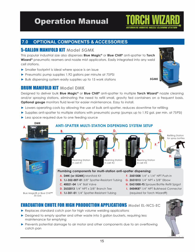
5-GALLON MANIFOLD KIT Model 5GMKThis popular industrial size also dispenses Blue Magic® or Blue Chill® anti-spatter to Torch Wizard® pneumatic reamers and nozzle mist applicators. Easily integrated into any weld cell stations.
► Smaller footprint is ideal where space is an issue► Pneumatic pump supplies 1.92 gallons per minute at 75PSI► Bulk dispensing system easily supplies up to 15 work stations
DRUM MANIFOLD KIT Model DMKDesigned to deliver bulk Blue Magic® or Blue Chill® anti-spatter to multiple Torch Wizard® nozzle cleaning and/or spraying stations, eliminating the need to refill small, gravity fed containers on a frequent basis. Optional gauge monitors fluid level for easier maintenance. Easy to install.
► Lowers operating costs by allowing the use of bulk anti-spatter, reduces downtime for refilling► Supplies anti-spatter to multiple stations with pneumatic pump (pumps up to 1.92 gal. per min. at 75PSI)► Less space required due to one feeding source
Plumbing components for multi-station anti-spatter dispensing: A. DMK (or 5GMK) Manifold Kit F. 2U01008 1/4” x 1/4” NPT Push-in B. 1J-352-007-01 3/8” Spatter-Resistant Tubing G. 2U31013 1/4” NPT x 3/8” Elbow C. 40021-04 1/4” Ball Valve H. EAS1000-FS Sprayer/Bottle Refill Spigot D. 2U32013 1/4” NPT x 3/8” Branch Tee I. 5454K87 1/4” NPT Bulkhead Connector E. 1J-351-01 1/4” Spatter-Resistant Tubing (required for Torch Wizard®)
Reaming Stationin cell #1
Reaming Stationin cell #2
Reaming Stationin cell #3
Refilling Station for spray bottles
A. ANTI-SPATTER MULTI-STATION DISPENSING SYSTEM SETUPB.
C.
D.
E.F.
G.
H.I.
DMK
Blue Magic® or Blue Chill™55 Gal.
EVACUATION CHUTE FOR HIGH PRODUCTION APPLICATIONS Model EL-NCS-EC► Replaces standard catch pan for high volume welding applications ► Designed to empty spatter and other waste into 5 gallon buckets, requiring less maintenance for emptying► Prevents potential damage to air motor and other components due to an overflowing catch pan
7.0 OPTIONAL COMPONENTS & ACCESSORIES

ENTERPRISES, INC.5750 Marathon Drive • Jackson, MI 49201 • (517) 782-8040 • Fax: (517) 782-8039www.wire-wizard.com