Award BIOSps-2.kev009.com/basil.holloway/ALL PDF/MX6E-AWD.pdf · AWARD BIOS 3-4 Standard CMOS à...
38
3-1 Chapter 3 Award BIOS This chapter tells how to configure the system parameters. You may update your BIOS via AWARD Flash Utility. Important: Because the BIOS code is the most often changed part of the mainboard design, the BIOS information contained in this chapter (especially the Chipset Setup parameters) may be a little different compared to the actual BIOS that came with your mainboard.
Transcript of Award BIOSps-2.kev009.com/basil.holloway/ALL PDF/MX6E-AWD.pdf · AWARD BIOS 3-4 Standard CMOS à...

3-1
Chapter 3
Award BIOS
This chapter tells how to configure the system parameters. You may updateyour BIOS via AWARD Flash Utility.
Important: Because the BIOS code is the mostoften changed part of the mainboard design, theBIOS information contained in this chapter(especially the Chipset Setup parameters) may bea little different compared to the actual BIOS thatcame with your mainboard.

AWARD BIOS
3-2
3.1 Entering the Award BIOS Setup Menu
The BIOS setup utility is a segment of codes/routines residing in the BIOSFlash ROM. This routine allows you to configure the system parameters andsave the configuration into the 128 byte CMOS area, (normally in the RTC chipor directly in the main chipset). To enter the BIOS Setup, press duringPOST (Power-On Self Test). The BIOS Setup Main Menu appears as follows.
Tip: Choose "Load Setup Defaults" forrecommended optimal performance. Choose"Load Turbo Defaults" for best performancewith light system loading. Refer to section 3.7.
The section at the bottom of the screen tells how to control the screen. Use thearrow keys to move between items, to color scheme of the display,
to exit, and to save the changes before exit. Another section at thebottom of the screen displays a brief description of the highlighted item.
After selecting an item, press to select or enter a submenu.

AWARD BIOS
3-3
3.2 Standard CMOS Setup
The "Standard CMOS Setup" sets the basic system parameters such as thedate, time, and the hard disk type. Use the arrow keys to highlight an item and
or to select the value for each item.
Standard CMOS à Date
To set the date, highlight the Date parameter. Press or to set thecurrent date. The date format is month, date, and year.
Standard CMOS à Time
To set the time, highlight the Time parameter. Press or to set thecurrent time in hour, minute, and second format. The time is based on the 24hour military clock.

AWARD BIOS
3-4
Standard CMOS à Primary Master à TypeStandard CMOS à Primary Slave à TypeStandard CMOS à Secondary Master à TypeStandard CMOS à Secondary Slave à Type
TypeAutoUserNone12...45
This item lets you select the IDE hard disk parametersthat your system supports. These parameters are Size,Number of Cylinder, Number of Head, Start Cylinder forPre-compensation, Cylinder number of Head LandingZone and Number of Sector per Track. The defaultsetting is Auto, which enables BIOS to automaticallydetect the parameters of installed HDD at POST (Power-On Self Test). If you prefer to enter HDD parametersmanually, select User. Select None if no HDD isconnected to the system.
The IDE CDROM is always automatically detected.
Tip: For an IDE hard disk, we recommend thatyou use the "IDE HDD Auto Detection" to enterthe drive specifications automatically. See thesection "IDE HDD Auto Detection".
Standard CMOS à Primary Master à ModeStandard CMOS à Primary Slave à ModeStandard CMOS à Secondary Master à ModeStandard CMOS à Secondary Slave à Mode
ModeAutoNormalLBALarge
The enhanced IDE feature allows the system to use ahard disk with a capacity of more than 528MB. This ismade possible through the Logical Block Address (LBA)mode translation. The LBA is now considered as astandard feature of current IDE hard disk on the marketbecause of its capability to support capacity larger than528MB. Note that if HDD is formatted with LBA On, it willnot be able to boot with LBA Off.

AWARD BIOS
3-5
Standard CMOS à Drive AStandard CMOS à Drive B
Drive ANone360KB 5.25"1.2MB 5.25"720KB 3.5"1.44MB 3.5"2.88MB 3.5"
These items select floppy drive type. The available settingsand types supported by the mainboard are listed on the left.
Standard CMOS à Video
VideoEGA/VGACGA40CGA80Mono
This item specifies the type of video card in use. Thedefault setting is VGA/EGA. Since current PCs use VGAonly, this function is almost useless and may bedisregarded in the future.
Standard CMOS à Halt On
Halt OnNo ErrorsAll ErrorsAll, But KeyboardAll, But DisketteAll, But Disk/Key
This parameter enables you to control the system stops incase of Power-On Self Test (POST) error.

AWARD BIOS
3-6
3.3 BIOS Features Setup
This screen appears when you select the option "BIOS Features Setup" fromthe main menu.
BIOS Features à Virus Warning
Virus WarningEnabledDisabled
Set this parameter to Enabled to activate the warningmessage. This feature protects the boot sector and partitiontable of your hard disk from virus intrusion.
Any attempt during boot up to write to the boot sector of thehard disk drive stops the system and the following warningmessage appears on the screen. Run an anti-virus programto locate the problem.
! WARNING !Disk Boot Sector is to be modified
Type "Y" to accept write, or "N" to abort writeAward Software, Inc.

AWARD BIOS
3-7
BIOS Features à External Cache
External CacheEnabledDisabled
Enabling this parameter activates the secondary cache(currently, PBSRAM cache). Disabling the parameterslows down the system. Therefore, we recommend thatyou leave it enabled unless you are troubleshooting aproblem.
BIOS Features à CPU L2 Cache ECC Checking
CPU L2 CacheECC CheckingEnabledDisabled
This item lets you enable or disable L2 Cache ECCchecking.
BIOS Features à Quick Power On Self Test
Quick Power onSelf testEnableDisabled
This parameter speeds up POST by skipping some itemsthat are normally checked.
BIOS Features à Boot Sequence
Boot SequenceA,C,SCSIC,A,SCSIC,CDROM,ACDROM,C,AD,A,SCSIE,A,SCSIF,A,SCSISCSI,A,CSCSI,C,AC onlyLS/ZIP,C
This parameter allows you to specify the system boot upsearch sequence. The hard disk ID are listed below:
C: Primary master
D: Primary slave
E: Secondary master
F: Secondary slave
LS: LS120
Zip: IOMEGA ZIP Drive

AWARD BIOS
3-8
BIOS Features à Swap Floppy Drive
Swap Floppy DriveEnabledDisabled
This item allows you to swap floppy drives. For example,if you have two floppy drives (A and B), you can assign thefirst drive as drive B and the second drive as drive A orvice-versa.
BIOS Features à Boot Up NumLock Status
Boot Up NumLockStatusOnOff
Setting this parameter to On enables the numeric functionof the numeric keypad. Set this parameter to Off todisregard the function. Disabling the numeric functionallows you to use the numeric keypad for cursor control.
BIOS Features à Boot Up System Speed
Boot Up SystemSpeedHighLow
Select High or Low system speed after boot.
BIOS Features à Typematic Rate Setting
Typematic RateSettingEnabledDisabled
Set this parameter to Enable/Disable the keyboardrepeat function. When enabled, continually holding downa key on the keyboard will generate repeatedlykeystrokes.
BIOS Features à Typematic Rate (Chars/Sec)
Typematic Rate68101215202430
This item allows you to control the speed of repeatedkeystrokes. The default is 30 characters/sec.
AWARD BIOS
3-9
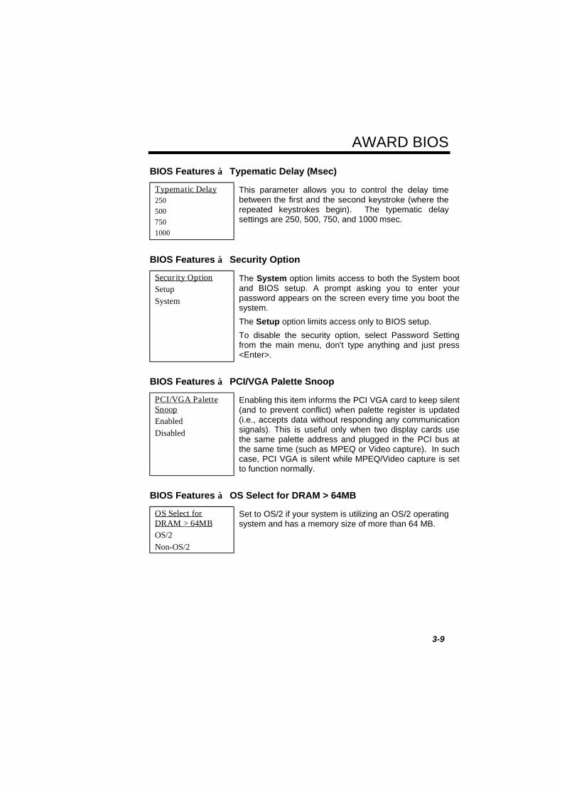
BIOS Features à Typematic Delay (Msec)
Typematic Delay2505007501000
This parameter allows you to control the delay timebetween the first and the second keystroke (where therepeated keystrokes begin). The typematic delaysettings are 250, 500, 750, and 1000 msec.
BIOS Features à Security Option
Security OptionSetupSystem
The System option limits access to both the System bootand BIOS setup. A prompt asking you to enter yourpassword appears on the screen every time you boot thesystem.
The Setup option limits access only to BIOS setup.
To disable the security option, select Password Settingfrom the main menu, don't type anything and just press<Enter>.
BIOS Features à PCI/VGA Palette Snoop
PCI/VGA PaletteSnoopEnabledDisabled
Enabling this item informs the PCI VGA card to keep silent(and to prevent conflict) when palette register is updated(i.e., accepts data without responding any communicationsignals). This is useful only when two display cards usethe same palette address and plugged in the PCI bus atthe same time (such as MPEQ or Video capture). In suchcase, PCI VGA is silent while MPEQ/Video capture is setto function normally.
BIOS Features à OS Select for DRAM > 64MB
OS Select forDRAM > 64MBOS/2Non-OS/2
Set to OS/2 if your system is utilizing an OS/2 operatingsystem and has a memory size of more than 64 MB.

AWARD BIOS
3-10
BIOS Features à Video BIOS Shadow
Video BIOSShadowEnabledDisabled
VGA BIOS Shadowing means to copy video displaycard BIOS into the DRAM area. This enhances systemperformance because DRAM access time is faster thanROM.
BIOS Features à C800-CBFF ShadowBIOS Features à CC00-CFFF ShadowBIOS Features à D000-D3FF ShadowBIOS Features à D400-D7FF ShadowBIOS Features à D800-DBFF ShadowBIOS Features à DC00-DFFF Shadow
C8000-CBFFFShadowEnabledDisabled
These six items are for shadowing ROM code on otherexpansion cards. Before you set these parameters, youneed to know the specific addresses of that ROM code.If you do not know this information, enable all the ROMshadow settings.
Note: The F000 and E000 segments arealways shadowed because BIOS codeoccupies these areas.

AWARD BIOS
3-11
3.4 Chipset Features Setup
The "Chipset Features Setup" includes settings for the chipset dependentfeatures. These features are related to system performance.
Caution: Make sure you fully understand theitems contained in this menu before you try tochange anything. You may change theparameter settings to improve systemperformance . However, it may cause systemunstable if the setting are not correct for yoursystem configuration.

AWARD BIOS
3-12
Chipset Features à Auto Configuration
Auto ConfigurationEnabledDisabled
When Enabled, the DRAM and cache related timingare set to pre-defined value according to CPU typeand clock. Select Disable if you want to specify yourown DRAM timing.
Chipset Features à DRAM Speed Selection
DRAM SpeedSelection50 ns60 ns
There are two sets of DRAM timing parameters canbe automatically set by BIOS, 50ns and 60ns.
Chipset Features à MA Wait State
MA Wait StateSlowFast
To enable or disable one additional MA (DRAMmemory address) wait state. The default setting isSlow. Set it to Fast if you have heavy loading (manychip count) or lower speed DRAM.
Chipset Features à EDO RAS# to CAS# Delay
EDO RAS# to CAS#Delay23
This option allows you to set the wait state betweenrow address strobe (RAS) and column address strobe(CAS) signals.
Chipset Features à EDO RAS# Precharge Time
EDO RAS#Precharge Time34
This parameter specifies the number of clocksrequired to deassert the RAS signal to prevent DRAMfrom losing data after performing a read. Thisoperation is called Precharge.
AWARD BIOS
3-13
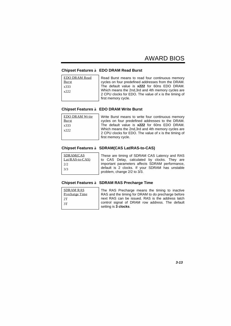
Chipset Features à EDO DRAM Read Burst
EDO DRAM ReadBurstx333x222
Read Burst means to read four continuous memorycycles on four predefined addresses from the DRAM.The default value is x222 for 60ns EDO DRAM.Which means the 2nd,3rd and 4th memory cycles are2 CPU clocks for EDO. The value of x is the timing offirst memory cycle.
Chipset Features à EDO DRAM Write Burst
EDO DRAM WriteBurstx333x222
Write Burst means to write four continuous memorycycles on four predefined addresses to the DRAM.The default value is x222 for 60ns EDO DRAM.Which means the 2nd,3rd and 4th memory cycles are2 CPU clocks for EDO. The value of x is the timing offirst memory cycle.
Chipset Features à SDRAM(CAS Lat/RAS-to-CAS)
SDRAM(CASLat/RAS-to-CAS)2/23/3
These are timing of SDRAM CAS Latency and RASto CAS Delay, calculated by clocks. They areimportant parameters affects SDRAM performance,default is 2 clocks. If your SDRAM has unstableproblem, change 2/2 to 3/3.
Chipset Features à SDRAM RAS Precharge Time
SDRAM RASPrechatge Time2T3T
The RAS Precharge means the timing to inactiveRAS and the timing for DRAM to do precharge beforenext RAS can be issued. RAS is the address latchcontrol signal of DRAM row address. The defaultsetting is 3 clocks.

AWARD BIOS
3-14
Chipset Features à DRAM ECC Function
DRAM ECCFunctionEnabledDisabled
This item lets you enable or disable DRAM ECCfunction. The ECC algorithm has the ability to detectdouble bit error and automatically correct single biterror.
Chipset Features à CPU-to-PCI IDE Posting
CPU-to-PCI IDEPostingEnabledDisabled
To enable or disable CPU to PCI IDE post write cycle.The IDE write cycles will be queued in the FIFO orbuffer, and CPU can be released to do next job.Disable it, if you find any IDE compatibility problem.
Chipset Features à Video BIOS Cacheable
Video BIOSCacheableEnabledDisabled
Allows the video BIOS to be cached to allow fastervideo performance.
Chipset Features à Video RAM Cacheable
Video RAMCacheableEnabledDisabled
This item lets you cache Video RAM A000 and B000.
Chipset Features à 8 Bit I/O Recovery Time
8 Bit I/O RecoveryTime12345678NA
For some old I/O chips, after the execution of an I/Ocommand, the device requires a certain amount oftime (recovery time) before the execution of the nextI/O command. Because of new generation CPU andmainboard chipset, the assertion of I/O command isfaster, and sometimes shorter than specified I/Orecovery time of old I/O devices. This item lets youspecify the delay of 8-bit I/O command by count ofISA bus clock. If you find any unstable 8-bit I/O card,you may try to extend the I/O recovery time via thisitem. The BIOS default value is 4 ISA clock. If set toNA, the chipset will insert 3.5 system clocks.
AWARD BIOS
3-15
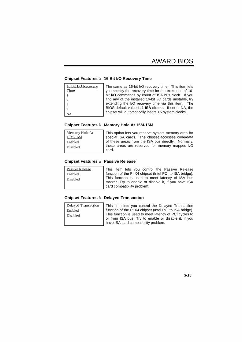
Chipset Features à 16 Bit I/O Recovery Time
16 Bit I/O RecoveryTime1234NA
The same as 16-bit I/O recovery time. This item letsyou specify the recovery time for the execution of 16-bit I/O commands by count of ISA bus clock. If youfind any of the installed 16-bit I/O cards unstable, tryextending the I/O recovery time via this item. TheBIOS default value is 1 ISA clocks. If set to NA, thechipset will automatically insert 3.5 system clocks.
Chipset Features à Memory Hole At 15M-16M
Memory Hole At15M-16MEnabledDisabled
This option lets you reserve system memory area forspecial ISA cards. The chipset accesses code/dataof these areas from the ISA bus directly. Normally,these areas are reserved for memory mapped I/Ocard.
Chipset Features à Passive Release
Passive ReleaseEnabledDisabled
This item lets you control the Passive Releasefunction of the PIIX4 chipset (Intel PCI to ISA bridge).This function is used to meet latency of ISA busmaster. Try to enable or disable it, if you have ISAcard compatibility problem.
Chipset Features à Delayed Transaction
Delayed TransactionEnabledDisabled
This item lets you control the Delayed Transactionfunction of the PIIX4 chipset (Intel PCI to ISA bridge).This function is used to meet latency of PCI cycles toor from ISA bus. Try to enable or disable it, if youhave ISA card compatibility problem.
AWARD BIOS
3-16
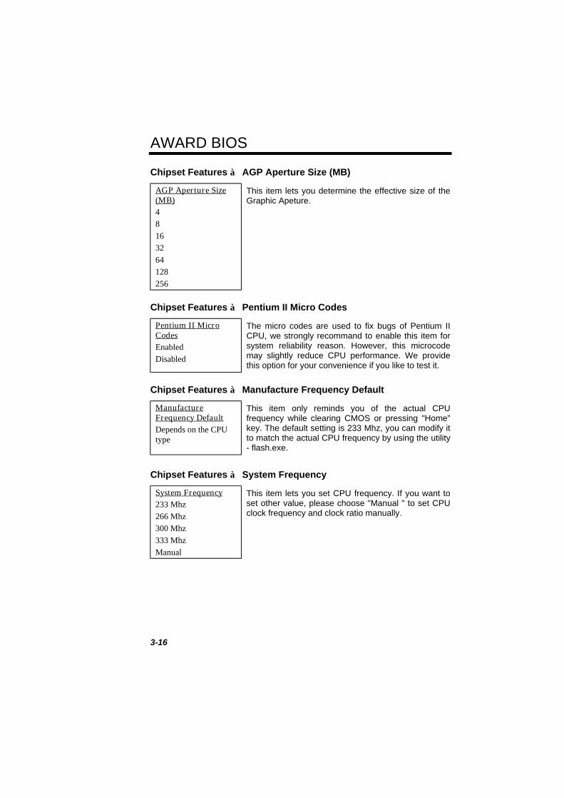
Chipset Features à AGP Aperture Size (MB)
AGP Aperture Size(MB)48163264128256
This item lets you determine the effective size of theGraphic Apeture.
Chipset Features à Pentium II Micro Codes
Pentium II MicroCodesEnabledDisabled
The micro codes are used to fix bugs of Pentium IICPU, we strongly recommand to enable this item forsystem reliability reason. However, this microcodemay slightly reduce CPU performance. We providethis option for your convenience if you like to test it.
Chipset Features à Manufacture Frequency Default
ManufactureFrequency DefaultDepends on the CPUtype
This item only reminds you of the actual CPUfrequency while clearing CMOS or pressing "Home”key. The default setting is 233 Mhz, you can modify itto match the actual CPU frequency by using the utility- flash.exe.
Chipset Features à System Frequency
System Frequency233 Mhz266 Mhz300 Mhz333 MhzManual
This item lets you set CPU frequency. If you want toset other value, please choose "Manual " to set CPUclock frequency and clock ratio manually.

AWARD BIOS
3-17
Chipset Features à CPU Clock Frequency
CPU ClockFrequency66.8 Mhz68.5 Mhz75.0 Mhz83.3 Mhz
This item lets you set external clock (bus clock). Thepossible settings of current Klamath CPU available onthe market are 66.8 Mhz, the correct setting may varybecause of new CPU product, refer to your CPUspecification for more details.
Chipset Features à CPU Clock Ratio
CPU Clock Ratio1.52.02.53.03.54.04.55.05.56.06.57.07.58.0
Intel Pentium II (Klamath) is designed to havedifferent Internal (Core) and External (Bus) frequency.This item lets you select the ratio of Core/Busfrequency. The default value is 3.5x.

AWARD BIOS
3-18
3.5 Power Management Setup
The Power Management Setup screen enables you to control the mainboardgreen features. See the following screen.
Power Management à Power Management
Power ManagementMax SavingMix SavingUser DefineDisabled
This function allows you to set the default parametersof power-saving modes. Set to Disable to turn offpower management function. Set to User Define tochoose your own parameters.
Mode Doze Standby Suspend HDD Power DownMin Saving 1 hour 1 hour 1 hour 15 minMax Saving 1 min 1 min 1 min 1 min

AWARD BIOS
3-19
Power Management à PM Controlled by APM
PM Controlled byAPMYesNo
If "Max Saving" is selected, you can turn on this item,transfer power management control to APM(Advanced Power Management) and enhance powersaving function. For example, stop CPU internalclock.
Power Management à Video Off After
Video Off AfterN/ADozeStandbySuspend
To turn off video monitor at which power down mode.
Power Management à Doze Mode
Doze ModeDisabled1 Min2 Min4 Min8 Min12 Min20 Min30 Min40 Min1 Hour
This item lets you set the period of time after whichthe system enters into Doze mode. The systemactivity (or event) is detected by monitoring the IRQsignals or other events (such as I/O).

AWARD BIOS
3-20
Power Management à Standby Mode
Standby ModeDisabled1 Min2 Min4 Min8 Min12 Min20 Min30 Min40 Min1 Hour
This item lets you set the period of time after whichthe system enters into Standby mode. In this mode,the monitor power-saving feature activates. Anyactivity detected returns the system to full power. Thesystem activity (or event) is detected by monitoringthe IRQ signals or other events (such as I/O).
Power Management à Suspend Mode
Suspend ModeDisabled1 Min2 Min4 Min8 Min12 Min20 Min30 Min40 Min1 Hour
This item lets you set the period of time after whichthe system enters into Suspend mode. The Suspendmode can be Power On Suspend or Suspend to HardDrive, selected by "Suspend Mode Option".
Power Management à HDD Power Down
HDD Power DownDisabled1 Min.....15 Min
This option lets you specify the IDE HDD idle timebefore the device enters the power down state. Thisitem is independent from the power states previouslydescribed in this section (Standby and Suspend).

AWARD BIOS
3-21
Power Management à Modem Wake Up
Modem Wake UpEnabledDisabled
This option lets you specify enable or disable ModemWake Up function.
Power Management à LAN Wake Up
LAN Wake UpEnabledDisabled
This option lets you specify enable or disable LANWake Up function.
Power Management à Suspend Mode Option
Suspend ModemOptionPowerOn SuspendSuspend to Disk
You can select suspend mode by this item. PowerOn Suspend is the traditional Green PC suspendmode, the CPU clock is stop, all other devices areshut off. But power must be kept On to detectactivities from modem, keyboard/mouse and returnsthe system to full power. The system activities isdetected by monitoring the IRQ signals or I/O.Suspend to Hard Drive saves system status,memory and screen image into hard disk, then thepower can be totally Off. Next time, when power isturned On, the system goes back to your original workwithin just few seconds, which depending on yourmemory size. You need utility AOZVHDD to reservedisk space.
Power Management à VGA Active Monitor
VGA Active MonitorEnabledDisabled
To enable or disable the detection of VGA activity forpower down state transition.

AWARD BIOS
3-22
Power Management à Power Button Override
Power ButtonOverrideEnabledDisabled
This is a specification of ACPI and supported byhardware. When Enabled, the soft power switch onthe front panel can be used to control power On,Suspend and Off. If the switch is pressed less than 4sec during power On, the system will go into Suspendmode. If the switch is pressed longer than 4 sec, thesystem will be turned Off. The default setting isDisabled, soft power switch is only used to control Onand Off, there is no need to press 4 sec, and there isno Suspend.
Power Management à RTC Wake Up Timer
RTC Wake Up TimerEnabledDisabled
This option lets you enable or disable the RTC WakeUp function.
Power Management à WakeUp Date (of Month)
WakeUp Date (ofMonth)01.....31
This item is displayed when you enable the RTCWake Up Timer option. Here you can specify whatdate you want to wake up the system. For Example,setting to 15 will wake up the system on the 15th dayof every month.
Note: Setting this item to 0 will wake up thesystem on the specified time (which can beset in the WakeUp Time item) every day.
AWARD BIOS
3-23
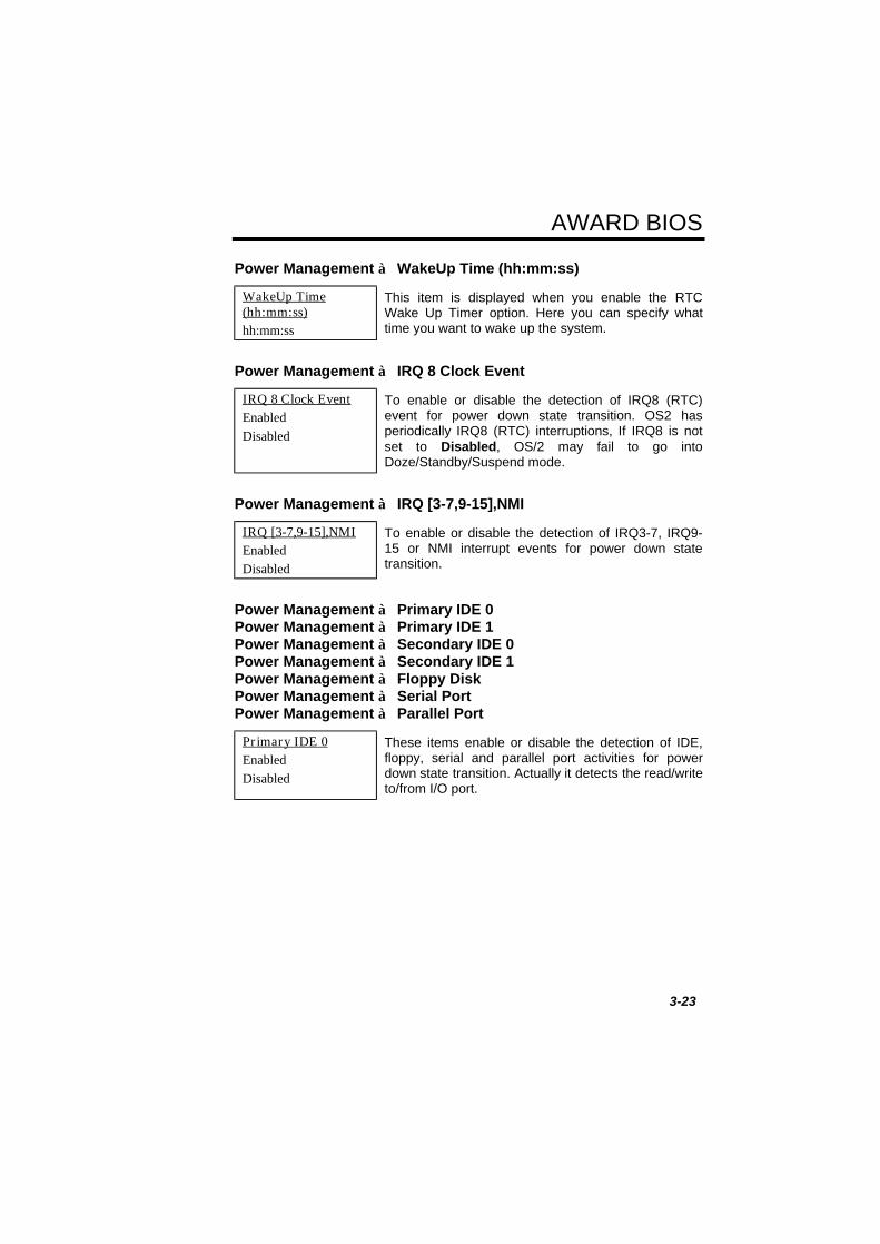
Power Management à WakeUp Time (hh:mm:ss)
WakeUp Time(hh:mm:ss)hh:mm:ss
This item is displayed when you enable the RTCWake Up Timer option. Here you can specify whattime you want to wake up the system.
Power Management à IRQ 8 Clock Event
IRQ 8 Clock EventEnabledDisabled
To enable or disable the detection of IRQ8 (RTC)event for power down state transition. OS2 hasperiodically IRQ8 (RTC) interruptions, If IRQ8 is notset to Disabled, OS/2 may fail to go intoDoze/Standby/Suspend mode.
Power Management à IRQ [3-7,9-15],NMI
IRQ [3-7,9-15],NMIEnabledDisabled
To enable or disable the detection of IRQ3-7, IRQ9-15 or NMI interrupt events for power down statetransition.
Power Management à Primary IDE 0Power Management à Primary IDE 1Power Management à Secondary IDE 0Power Management à Secondary IDE 1Power Management à Floppy DiskPower Management à Serial PortPower Management à Parallel Port
Primary IDE 0EnabledDisabled
These items enable or disable the detection of IDE,floppy, serial and parallel port activities for powerdown state transition. Actually it detects the read/writeto/from I/O port.
AWARD BIOS
3-24
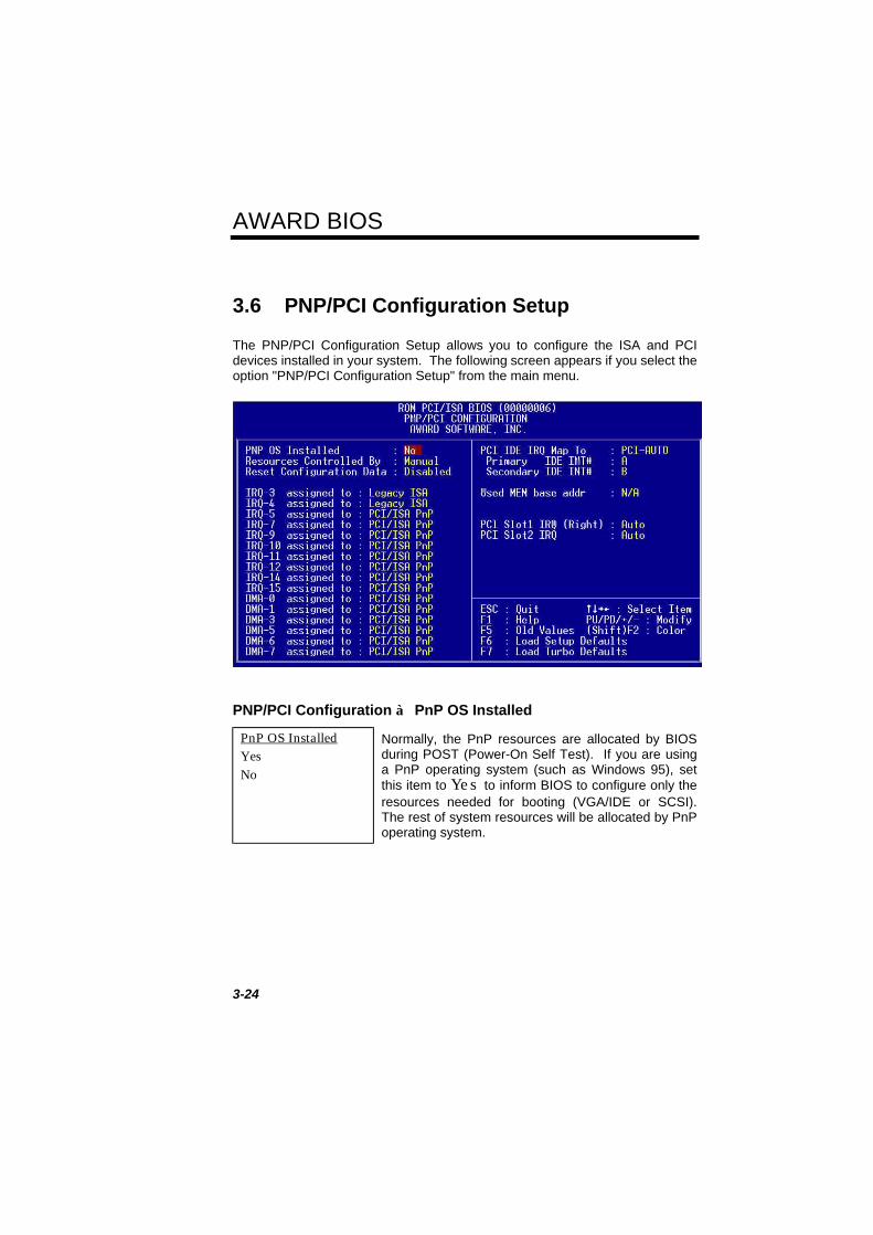
3.6 PNP/PCI Configuration Setup
The PNP/PCI Configuration Setup allows you to configure the ISA and PCIdevices installed in your system. The following screen appears if you select theoption "PNP/PCI Configuration Setup" from the main menu.
PNP/PCI Configuration à PnP OS Installed
PnP OS InstalledYesNo
Normally, the PnP resources are allocated by BIOSduring POST (Power-On Self Test). If you are usinga PnP operating system (such as Windows 95), setthis item to Yes to inform BIOS to configure only theresources needed for booting (VGA/IDE or SCSI).The rest of system resources will be allocated by PnPoperating system.

AWARD BIOS
3-25
PNP/PCI Configuration à Resources Controlled By
Resources ControlledbyAutoManual
Setting this option to Manual allows you to individuallyassign the IRQs and DMAs to the ISA and PCIdevices. Set this to Auto to enable the auto-configuration function.
PNP/PCI Configuration à Reset Configuration Data
Reset ConfigurationDataEnabledDisabled
In case conflict occurs after you assign the IRQs orafter you configure your system, you can enable thisfunction, allow your system to automatically reset yourconfiguration and reassign the IRQs, DMAs, and I/Oaddress.
PNP/PCI Configuration à IRQ3 (COM2)PNP/PCI Configuration à IRQ4 (COM1)PNP/PCI Configuration à IRQ5 (Network/Sound or Others)PNP/PCI Configuration à IRQ7 (Printer or Others)PNP/PCI Configuration à IRQ9 (Video or Others)PNP/PCI Configuration à IRQ10 (SCSI or Others)PNP/PCI Configuration à IRQ11 (SCSI or Others)PNP/PCI Configuration à IRQ12 (PS/2 Mouse)PNP/PCI Configuration à IRQ14 (IDE1)PNP/PCI Configuration à IRQ15 (IDE2)
IRQ 3Legacy ISAPCI/ISA PnP
If your ISA card is not PnP compatible and requires aspecial IRQ to support its function, set the selectedIRQ to Legacy ISA. This setting informs the PnPBIOS to reserve the selected IRQ for the installedlegacy ISA card. The default is PCI/ISA PnP. Takenote that PCI cards are always PnP compatible(except old PCI IDE card).

AWARD BIOS
3-26
PNP/PCI Configuration à DMA 0PNP/PCI Configuration à DMA 1PNP/PCI Configuration à DMA 3PNP/PCI Configuration à DMA 5PNP/PCI Configuration à DMA 6PNP/PCI Configuration à DMA 7
DMA 0Legacy ISA
PCI/ISA PnP
If your ISA card is not PnP compatible and requires aspecial DMA channel to support its function, set theselected DMA channel to Legacy ISA. This setting informsthe PnP BIOS to reserve the selected DMA channel for theinstalled legacy ISA card. The default is PCI/ISA PnP.Take note that PCI card does not require DMA channel.
PNP/PCI Configuration à PCI IDE IRQ Map To
PCI IDE IRQ MapToISAPCI-Slot1PCI-Slot2PCI-Slot3PCI-Slot4PCI-Auto
Some old PCI IDE add-on cards are not fully PnPcompatible. These cards require you to specify theslot in use to enable BIOS to properly configure thePnP resources. This function allows you to select thePCI slot for any PCI IDE add-on card present in yoursystem. Set this item to Auto to allow BIOS toautomatically configure the installed PCI IDE card(s).
PNP/PCI Configuration à Primary IDE INT#PNP/PCI Configuration à Secondary IDE INT#
Primary IDE INT#ABCD
These two items, in conjunction with item "PCI IDEIRQ Map To", specify the IRQ routing of the primaryor secondary channel of the PCI IDE add-on card (notthe onboard IDE). Each PCI slot has four PCIinterrupts aligned as listed in the table below. Youmust specify the slot in the "PCI IDE IRQ Map To",and set the PCI interrupt (INTx) here according to theinterrupt connection on the card.

AWARD BIOS
3-27
PCI Slot Location 1(pin A6)
Location 2(pin B7)
Location 3(pin A7)
Location 4(pin B8)
Slot 1 INTA INTB INTC INTDSlot 2 INTB INTC INTD INTASlot 3 INTC INTD INTA INTBSlot 4 INTD INTA INTB INTCSlot 5 (if any) INTD INTA INTB INTC
PNP/PCI Configuration à Used MEM Base Addr
Used MEM base addrN/AC800CC00D000D400D800DC00
This item, in conjunction with the "Used MEMLength", lets you set a memory space for non-PnPcompatible ISA card. This item specifies thememory base (start address) of the reservedmemory space. The memory size is specified in the"Used MEM Length".
PNP/PCI Configuration à Used MEM Length
Used MEM Length8K16K32K64K
If your ISA card is not PnP compatible and requiresspecial memory space to support its function,specify the memory size in this parameter to informthe PnP BIOS to reserve the specified memoryspace for installed legacy ISA card.

AWARD BIOS
3-28
PNP/PCI Configuration à PCI Slot1 IRQ (Right)PNP/PCI Configuration à PCI Slot2 IRQ
PCI Slot1 IRQ345791011121415Auto
This item is reserved for engineering purpose to letyou assign an IRQ manually to the add-on card oneach PCI slot. If you select Auto, system willautomatically assign an available value to the device.
It is suggested to use default setting, which is Auto, inorder to comply with PnP specification completely.
AWARD BIOS
3-29
3.7 Load Setup Defaults
The "Load Setup Defaults" option loads optimized settings for optimum systemperformance. Optimal settings are relatively safer than the Turbo settings. Werecommend you to use the Optimal settings if your system has large memorysize and fully loaded with add-on card (for example, a file server using double-sided 8MB SIMM x4 and SCSI plus Network card occupying the PCI and ISAslots).
Optimal is not the slowest setting for this mainboard. If you need to verify aunstable problem, you may manually set the parameter in the "BIOS FeaturesSetup" and "Chipset Features Setup" to get slowest and safer setting.
3.8 Load Turbo Defaults
The "Load Turbo Defaults" option gives better performance than Optimalvalues. However, Turbo values may not be the best setting of this mainboardbut these values are qualified by the AOpen RD and QA department as thereliable settings especially if you have limited loading of add-on card andmemory size (for example, a system that contains only a VGA/Sound card andtwo SIMMs).
To attain the best system performance, you may manually set the parametersin the "Chipset Features Setup" to get proprietary setting. Make sure that youknow and understand the functions of every item in Chipset Setup menu. Theperformance difference of Turbo from Optimal is normally around 3% to 10%,depending on the chipset and the application.
AWARD BIOS
3-30
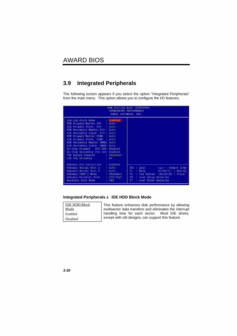
3.9 Integrated Peripherals
The following screen appears if you select the option "Integrated Peripherals"from the main menu. This option allows you to configure the I/O features.
Integrated Peripherals à IDE HDD Block Mode
IDE HDD BlockModeEnabledDisabled
This feature enhances disk performance by allowingmultisector data transfers and eliminates the interrupthandling time for each sector. Most IDE drives,except with old designs, can support this feature.

AWARD BIOS
3-31
Integrated Peripherals à IDE Primary Master PIOIntegrated Peripherals à IDE Primary Slave PIOIntegrated Peripherals à IDE Secondary Master PIOIntegrated Peripherals à IDE Secondary Slave PIO
IDE Primary MasterPIOAutoMode 1Mode 2Mode 3Mode 4
Setting this item to Auto activates the HDD speedauto-detect function. The PIO mode specifies thedata transfer rate of HDD. For example: mode 0data transfer rate is 3.3MB/s, mode 1 is 5.2MB/s,mode 2 is 8.3MB/s, mode 3 is 11.1MB/s and mode 4is 16.6MB/s. If your hard disk performance becomesunstable, you may manually try the slower mode.
Caution: It is recommended that you connectthe first IDE device of each channel to theendmost connector of the IDE cable. Refer tosection "Connectors" for details on how toconnect IDE device(s).
Integrated Peripherals à IDE Primary Master UDMAIntegrated Peripherals à IDE Primary Slave UDMAIntegrated Peripherals à IDE Secondary Master UDMAIntegrated Peripherals à IDE Secondary Slave UDMA
IDE Primary MasterUDMAAutoDisabled
This item allows you to set the Ultra DMA/33 modesupported by the hard disk drive connected to yourprimary IDE connector.
Integrated Peripherals à On-Chip Primary PCI IDEIntegrated Peripherals à On-Chip Secondary PCI IDE
On-Chip PrimaryPCI IDEEnabledDisabled
This parameter lets you enable or disable the IDEdevice connected to the primary IDE connector.
AWARD BIOS
3-32
Integrated Peripherals à USB Legacy Support
USB Legacy SupportEnabledDisabled
This item lets you enable or disable the USBkeyboard driver within the onboard BIOS. Thekeyboard driver simulates legacy keyboard commandand let you use USB keyboard during POST or afterboot if you don't have USB driver in the operatingsystem.
Caution: You can not use both USB driverand USB legacy keyboard at the same time.Disable "USB Legacy Support" if you haveUSB driver in the operating system.
Integrated Peripherals à USB IRQ Released
USB IRQ ReleasedYesNo
USB device is default to use PCI INTD#, the same asPCI slot4. If you installed PCI card on slot4 andrequire to use INTD#, set this item to Yes. The USBdevice will then be disabled.
Note: Normally, PCI VGA does not need PCIinterrupt, you may put PCI VGA on slot4.
Integrated Peripherals à Onboard FDC Controller
Onboard FDCControllerEnabledDisabled
Setting this parameter to Enabled allows you toconnect your floppy disk drives to the onboard floppydisk connector instead of a separate controller card.Change the setting to Disabled if you want to use aseparate controller card.

AWARD BIOS
3-33
Integrated Peripherals à Onboard Serial Port 1Integrated Peripherals à Onboard Serial Port 2
Onboard Serial Port1Auto3F8/IRQ42F8/IRQ33E8/IRQ42E8/IRQ3Disabled
This item allow you to assign address and interrupt forthe board serial port. Default is Auto.
Note: If you are using an network card, makesure that the interrupt does not conflict.
Integrated Peripherals à Onboard UART 2 Mode
Onboard UART 2ModeStandardHPSIRASKIR
This item is configurable only if the "Onboard UART2" is enabled. This allows you to specify the mode ofserial port2. The available mode selections are:
• Standard - Sets serial port 2 to operate in normal mode. This is thedefault setting.
• HPSIR - Select this setting if you installed an Infrared module in yoursystem via IrDA connector (refer to section 2.3 "Connectors"). Thissetting allows infrared serial communication at a maximum baud rate of115K baud.
• ASKIR - Select this setting if you installed an Infrared module via IrDAconnector (refer to section 2.3 "Connectors"). This setting allows infraredserial communication at a maximum baud rate of 19.2K baud.

AWARD BIOS
3-34
Integrated Peripherals à Onboard Parallel Port
Onboard ParallelPort3BC/IRQ7378/IRQ7278/IRQ5Disabled
This item controls the onboard parallel port addressand interrupt.
Note: If you are using an I/O card with aparallel port, make sure that the addressesand IRQ do not conflict.
Integrated Peripherals à Parallel Port Mode
Parallel Port ModeSPPEPPECPECP + EPP
This item lets you set the parallel port mode. Themode options are SPP (Standard and BidirectionParallel Port), EPP (Enhanced Parallel Port) and ECP(Extended Parallel Port). SPP is the IBM AT andPS/2 compatible mode. EPP enhances the parallelport throughput by directly writing/reading data to/fromparallel port without latch. ECP supports DMA andRLE (Run Length Encoded) compression anddecompression.
Integrated Peripherals à ECP Mode Use DMA
ECP Mode Use DMA31
This item lets you set the DMA channel of ECP mode.

AWARD BIOS
3-35
3.10 Password Setting
Password prevents unauthorized use of your computer. If you set a password,the system prompts for the correct password before boot or access to Setup.
To set a password:
1. At the prompt, type your password. Your password can be up to 8alphanumeric characters. When you type the characters, they appear asasterisks on the password screen box.
2. After typing the password, press.
3. At the next prompt, re-type your password and press again to confirm thenew password. After the password entry, the screen automatically revertsto the main screen.
To disable the password, press when prompted to enter the password. Thescreen displays a message confirming that the password has been disabled.
3.11 IDE HDD Auto Detection
If your system has an IDE hard drive, you can use this function to detect itsparameters and enter them into the "Standard CMOS Setup" automatically.
This routine only detects one set of parameters for your IDE hard drive. SomeIDE drives can use more than one set of parameters. If your hard disk isformatted using different parameters than those detected, you have to enter theparameters manually. If the parameters listed do not match the ones used toformat the disk, the information on that disk will not be accessible. If the auto-detected parameters displayed do not match those that used for your drive,ignore them. Type N to reject the values and enter the correct ones manuallyfrom the Standard CMOS Setup screen.
3.12 Save & Exit Setup
This function automatically saves all CMOS values before leaving Setup.

AWARD BIOS
3-36
3.13 Load EEPROM Default
Except "Load Setup Default" and "Load Turbo Default", you may also use"Save EEPROM Default " to save your own settings into EEPROM, and reloadby using this item.
3.14 Save EEPROM Default
You may use this item to save your own settings into EEPROM. Then, if thedata in CMOS is lost or you forget the previous settings, you may use "LoadEEPROM Default " to reload.
3.15 Exit without Saving
Use this function to exit Setup without saving the CMOS value changes. Donot use this option if you want to save the new configuration.
3.16 NCR SCSI BIOS and Drivers
The NCR 53C810 SCSI BIOS resides in the same flash memory chip as thesystem BIOS. The onboard NCR SCSI BIOS is used to support NCR 53C810SCSI control card without BIOS code.
The NCR SCSI BIOS directly supports DOS, Windows 3.1 and OS/2. Forbetter system performance, you may use the drivers that come with the NCRSCSI card or with your operating system. For details, refer to the installationmanual of your NCR 53C810 SCSI card.

AWARD BIOS
3-37
3.17 BIOS Flash Utility
The BIOS Flash utility allows you to upgrade the system BIOS. To get theAOpen Flash utility and the upgrade BIOS file, contact your local distributor orvisit our homepage at http://www.aopen.com.tw. Please make sure that youhave the correct BIOS ready, the BIOS filename is normally likeAP5TR110.BIN, which means model AP5T BIOS revision 1.10.
There are two useful programs, Checksum utility CHECKSUM.EXE and AOpenFlash utility AOFLASH.EXE. Follow the procedures below to upgrade yourBIOS.
[CHECKSUM.EXE]
This utility will help you to determine if the BIOS has been downloaded correctlyor not.
1. Execute
C:> CHECKSUM Biosfile.bin
Biosfile.bin is the filename of the BIOS code.
2. The utility will show "Checksum is ssss".
3. Compare the "ssss" with original checksum posted on Web or BBS. If theyare different, please do not proceed any further and try to download theBIOS again.
[AOFLASH.EXE]
This utility will try to check the mainboard model, BIOS version and Super/UltraIO chip model. To ensure the correct BIOS file for the correct mainboard andIO chip. This utility will permanently replace your original BIOS content afterflashing.
1. Bootup the system from floppy without loading any memory handler(HIMEM, EMM386, QEMM386, ...) or device driver.
2. Execute
C:> AOFLASH Biosfile.bin
Biosfile.bin is the filename of the BIOS code.

AWARD BIOS
3-38
3. After loading the new BIOS code, the utility will prompt you to save originalBIOS code into your HDD or floppy. Please press "Y" to store it as"BIOS.OLD".
4. After the old BIOS has been successfully saved, press "Y" to replace BIOS.
5. DO NOT turn off the power during "FLASHING".
6. Reboot the system by turn off the power after "FLASHING".
7. Press "DEL" key to enter BIOS setup during POST.
8. Reload the "BIOS SETUP DEFAULT" and reconfigure other items asprevious set.
9. Save & Exit. Done!
Warning: DO NOT turn off the power during"FLASHING". If the BIOS programming is notsuccessfully finished, the system will not be bootagain, and you may need to physically replace theBIOS chip.
Tip: You may load back original BIOS "BIOS.OLD" bythe same procedure.