AVR ISA & AVR Programming (I) - Computer Science and ...cs2121/LectureNotes/week4_notes.pdf ·...
68
Week4 1 AVR ISA & AVR Programming (I) Lecturer: Sri Parameswaran Notes by: Annie Guo
-
Upload
truongdieu -
Category
Documents
-
view
236 -
download
1
Transcript of AVR ISA & AVR Programming (I) - Computer Science and ...cs2121/LectureNotes/week4_notes.pdf ·...
Week4 1
AVR ISA &AVR Programming (I)
Lecturer: Sri ParameswaranNotes by: Annie Guo

Week4 2
Lecture Overview
AVR ISAAVR Instructions & Programming (I)
Basic construct implementation

Week4 3
Atmel AVR8-bit RISC architecture
Most instructions have 16-bit fixed lengthMost instructions take 1 clock cycle to execute.
Load-store memory access architectureAll calculations are on registers
Two-stage instruction pipeliningInternal program memory and data memoryWide variety of on-chip peripherals (digital I/O, ADC, EEPROM, UART, pulse width modulator (PWM) etc).
Week4 4
AVR Registers
General purpose registers32 8-bit registers, R0 ~ R31 or r0 ~ r31Can be further divided into two groups
First half group: R0 ~ R15 and second half group: R16 ~ R31Some instructions work only on the second half group R16~R31
Due to the limitation of instruction encoding bitsWill be covered later
E.g. ldi rd, #number ;rd ∈ R16~R31
Week4 5
AVR Registers (cont.)
General purpose registersThe following register pairs can work as address indexes
X, R26:R27Y, R28:R29Z, R31:R31
The following registers can be applied for specific use
R1:R0 store the result of multiplication instructionR0 stores the data loaded from the program memory
Week4 6
AVR Registers (cont.)I/O registers
64 8-bit registersTheir names are defined in the m64def.inc file
Used in input/output instructionsMainly storing data/addresses and control signal bits
Some instructions work only with I/O registers, others with general purpose registers – don’t confuse them
E.g. in rd, port ; port must be an I/O registerWill be covered in detail later
Status register (SREG)A special I/O register

Week4 7
The Status Register in AVRThe Status Register (SREG) contains information about the result of the most recently executed arithmetic instruction. This information can be used for altering program flow in order to perform conditional operations.SREG is updated after any of ALU operations by hardware.SREG is not automatically stored when entering an interrupt routine and restored when returning from an interrupt. This must be handled by software.
Using in/out instruction to store/restore SREG
Week4 8
The Status Register in AVR (cont.)
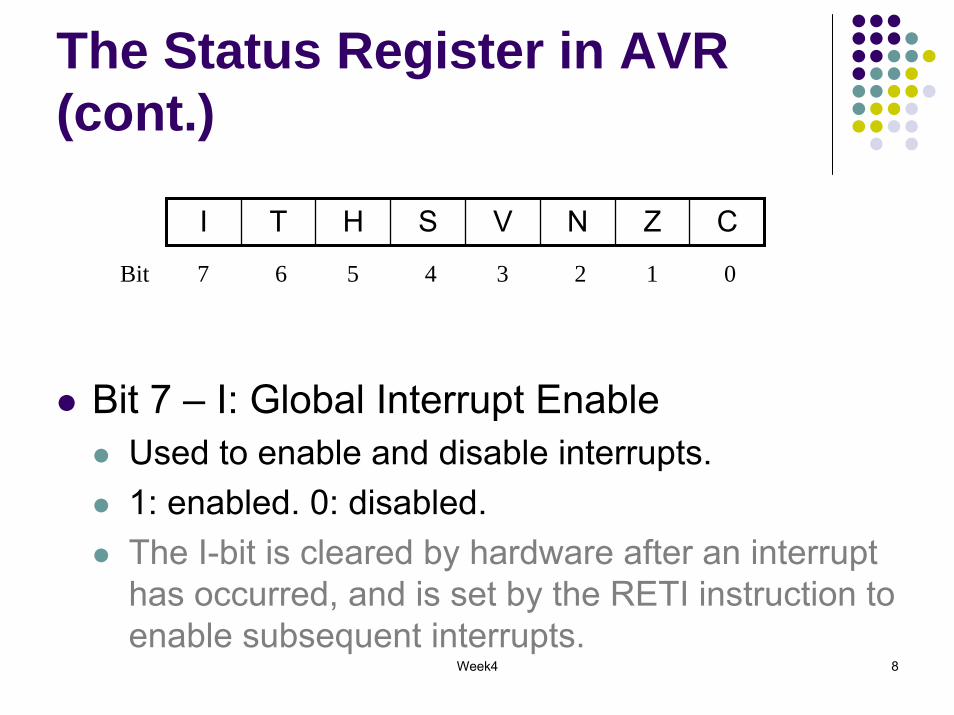
I T H S V N Z C
Bit 7 6 5 4 3 2 1 0
Bit 7 – I: Global Interrupt EnableUsed to enable and disable interrupts.1: enabled. 0: disabled. The I-bit is cleared by hardware after an interrupt has occurred, and is set by the RETI instruction to enable subsequent interrupts.
Week4 9
The Status Register in AVR (cont.)
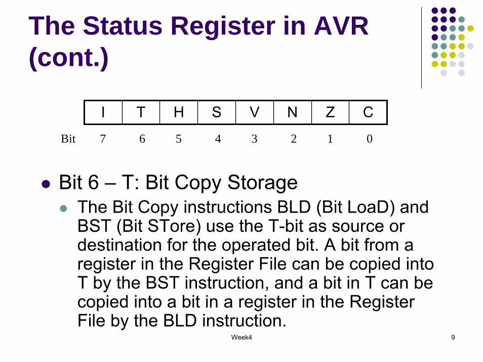
I T H S V N Z C
Bit 7 6 5 4 3 2 1 0
Bit 6 – T: Bit Copy StorageThe Bit Copy instructions BLD (Bit LoaD) and BST (Bit STore) use the T-bit as source or destination for the operated bit. A bit from a register in the Register File can be copied into T by the BST instruction, and a bit in T can be copied into a bit in a register in the Register File by the BLD instruction.

Week4 10
The Status Register in AVR (cont.)
I T H S V N Z C
Bit 7 6 5 4 3 2 1 0
Bit 5 – H: Half Carry FlagThe Half Carry Flag H indicates a Half Carry (carry from bit 4) in some arithmetic operations. Half Carry is useful in BCD arithmetic.

Week4 11
The Status Register in AVR (cont.)
I T H S V N Z C
Bit 7 6 5 4 3 2 1 0
Bit 4 – S: Sign BitExclusive OR between the Negative Flag N and the Two’s Complement Overflow Flag V ( S = N ⊕V).
Bit 3 – V: Two’s Complement Overflow FlagThe Two’s Complement Overflow Flag V supports two’s complement arithmetic.
Week4 12
The Status Register in AVR (cont.)
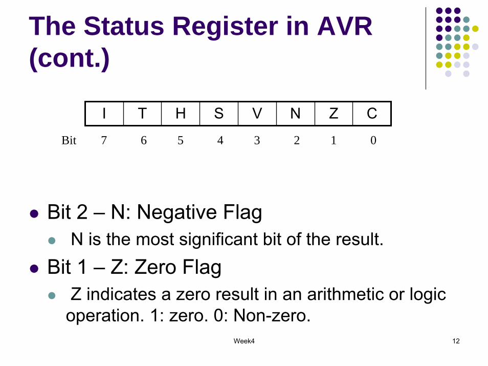
I T H S V N Z C
Bit 7 6 5 4 3 2 1 0
Bit 2 – N: Negative FlagN is the most significant bit of the result.
Bit 1 – Z: Zero FlagZ indicates a zero result in an arithmetic or logic operation. 1: zero. 0: Non-zero.
Week4 13
The Status Register in AVR (cont.)
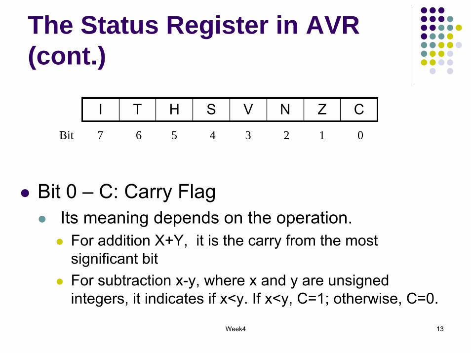
I T H S V N Z C
Bit 7 6 5 4 3 2 1 0
Bit 0 – C: Carry FlagIts meaning depends on the operation.
For addition X+Y, it is the carry from the most significant bitFor subtraction x-y, where x and y are unsigned integers, it indicates if x<y. If x<y, C=1; otherwise, C=0.
Week4 14
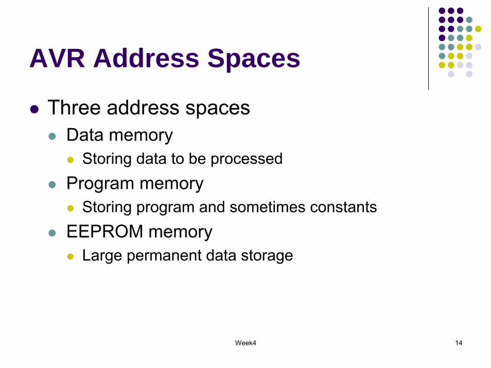
AVR Address Spaces
Three address spacesData memory
Storing data to be processed Program memory
Storing program and sometimes constantsEEPROM memory
Large permanent data storage

Week4 15
Data Memory SpaceCovers
Register fileI.e. registers in the register file also have memory address
I/O registersI.e. I/O registers have two versions of addresses
I/O addressesMemory addresses
SRAM data memoryThe highest memory location is defined as RAMEND
32 General purpose Working Registers
0x0000
0x1F
64 Input/Output Registers
Internal SRAM (128~4K bytes)
External SRAM
0x20
0x5F
End Address
Data Memory
0x60
8 bits
Week4 16
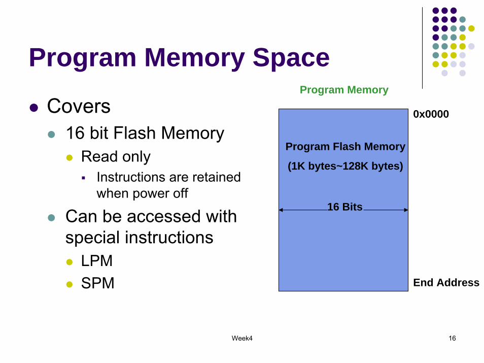
Program Memory SpaceProgram Memory
Covers 16 bit Flash Memory
Read onlyInstructions are retained when power off
Can be accessed with special instructions
LPMSPM
0x0000
16 Bits
Program Flash Memory
(1K bytes~128K bytes)
End Address
Week4 17
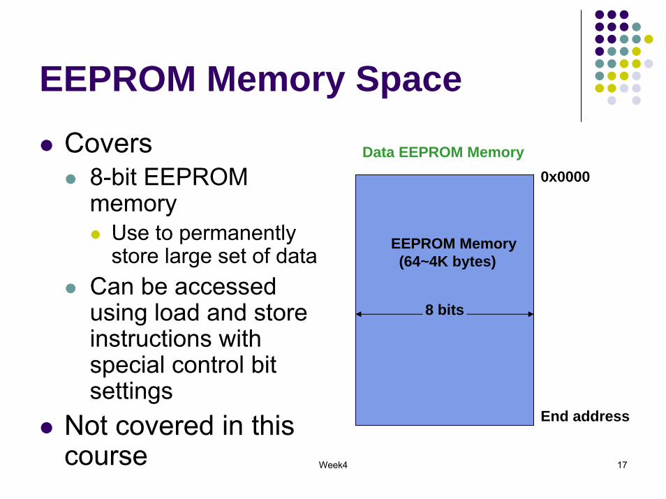
EEPROM Memory SpaceCovers
8-bit EEPROM memory
Use to permanently store large set of data
Can be accessed using load and store instructions with special control bit settings
Not covered in this course
Data EEPROM Memory0x0000
8 bits
EEPROM Memory (64~4K bytes)
End address

Week4 18
AVR Instruction Format
For AVR, almost all instructions are 16 bits long
add Rd, Rrsub Rd, Rrmul Rd, Rrbrge k
Few instructions are 32 bits longlds Rd, k ( 0 ≤ k ≤ 65535 )
loads 1 byte from the SRAM to a register.
Week4 19
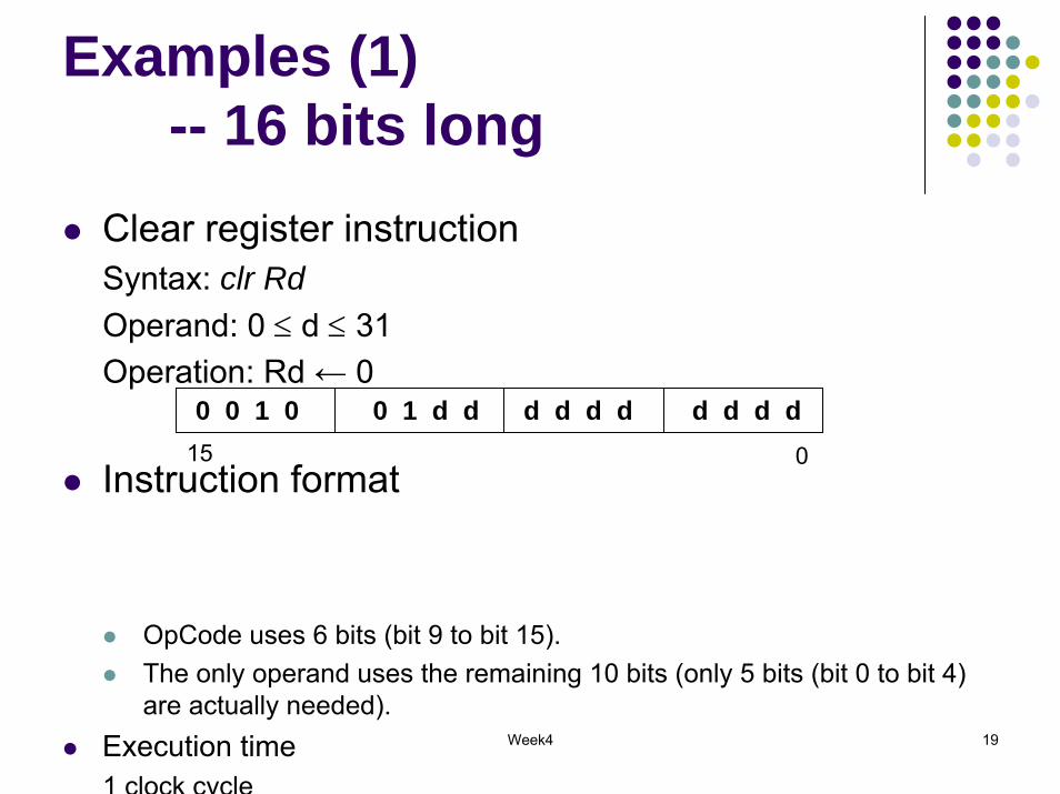
Examples (1)-- 16 bits long
Clear register instructionSyntax: clr RdOperand: 0 ≤ d ≤ 31Operation: Rd ← 0
Instruction format
OpCode uses 6 bits (bit 9 to bit 15).The only operand uses the remaining 10 bits (only 5 bits (bit 0 to bit 4) are actually needed).
Execution time1 clock cycle
0 0 1 0 0 1 d d d d d dd d d d015
Week4 20
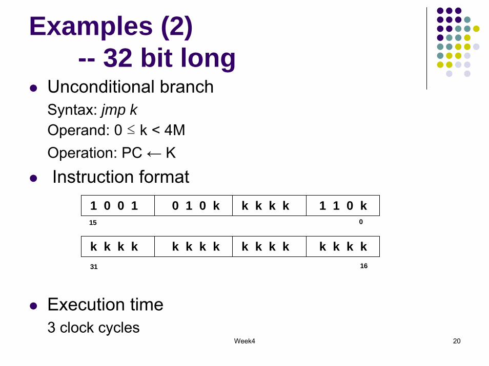
Examples (2)-- 32 bit long
Unconditional branchSyntax: jmp kOperand: 0 ≤ k < 4MOperation: PC ← KInstruction format
Execution time3 clock cycles
1 0 0 1 0 1 0 k 1 1 0 kk k k k15 0
k k k k k k k k k k k kk k k k31 16
Week4 21
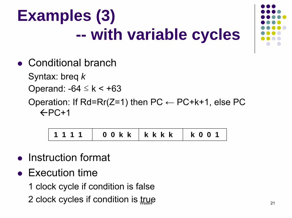
Examples (3)-- with variable cycles
Conditional branchSyntax: breq kOperand: -64 ≤ k < +63Operation: If Rd=Rr(Z=1) then PC ← PC+k+1, else PC
PC+1
Instruction formatExecution time1 clock cycle if condition is false2 clock cycles if condition is true
1 1 1 1 0 0 k k k 0 0 1k k k k
Week4 22
AVR Instructions
AVR has the following classes of instructions: Arithmetic and LogicData transferProgram control Bit and Others
Bit and Bit testMCU Control
An overview of the instructions are given in the next slides.
Week4 23
AL Instructions Arithmetic
addition E.g. ADD Rd, Rr
SubtractionE.g. SUB Rd, Rr
Increment/decrementE.g INC Rd
MultiplicationE.g. MUL Rd, Rr
Logic E.g. AND Rd, Rr
ShiftE.g. LSL Rd
Week4 24
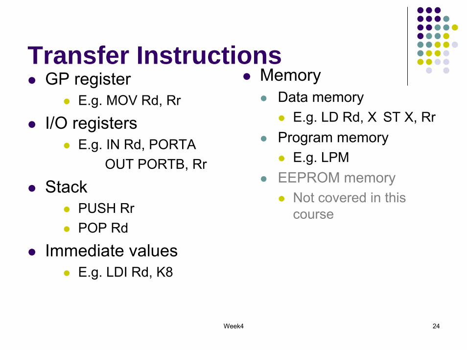
Transfer InstructionsGP register
E.g. MOV Rd, Rr
I/O registers E.g. IN Rd, PORTA
OUT PORTB, Rr
Stack PUSH RrPOP Rd
Immediate valuesE.g. LDI Rd, K8
MemoryData memory
E.g. LD Rd, X ST X, RrProgram memory
E.g. LPMEEPROM memory
Not covered in this course
Week4 25
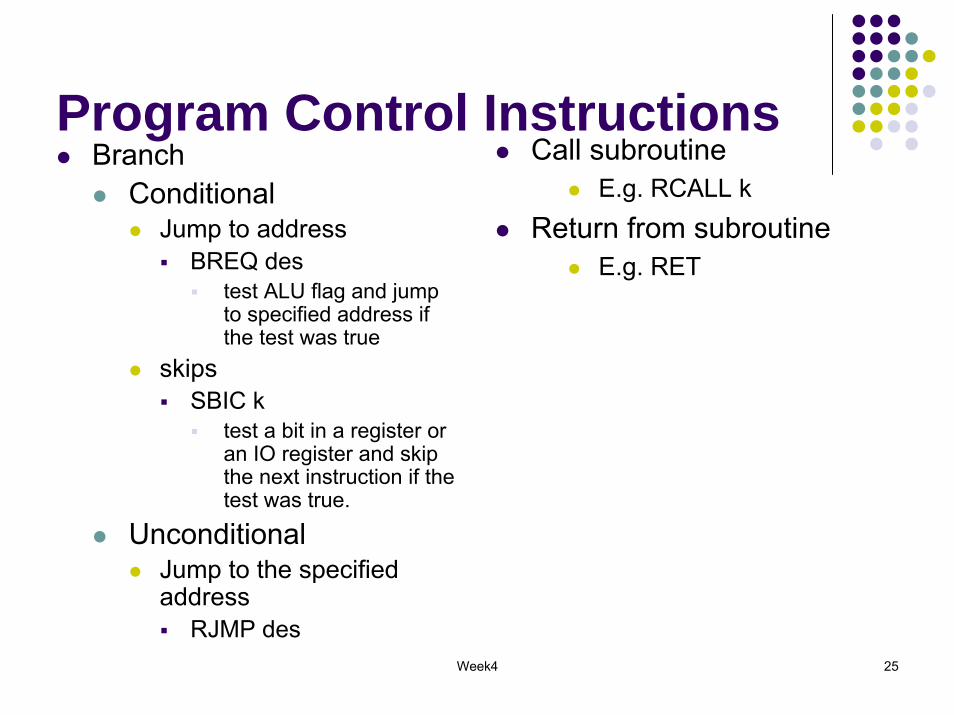
Program Control InstructionsBranch
Conditional Jump to address
BREQ destest ALU flag and jump to specified address if the test was true
skips SBIC k
test a bit in a register or an IO register and skip the next instruction if the test was true.
Unconditional Jump to the specified address
RJMP des
Call subroutine E.g. RCALL k
Return from subroutineE.g. RET

Week4 26
Bit & Other InstructionsBit
Set bitE.g. SBI PORTA, b
Clear bitE.g CBI PORTA, b
Bit copyE.g. BST Rd, b
OthersNOPBREAKSLEEPWDR
Week4 27
AVR Instructions (cont.)
Not all instructions are implemented in all AVR controllers.Refer to the data sheet of a specific microcontrollerRefer to online AVR instruction document for the detail description of each instruction

Week4 28
AVR Addressing ModesImmediate Register directMemory related addressing mode
Data memoryDirectIndirectIndirect with DisplacementIndirect with Pre-decrementIndirect with Post-increment
Program memoryEPROM memory
Not covered in this course
Week4 29
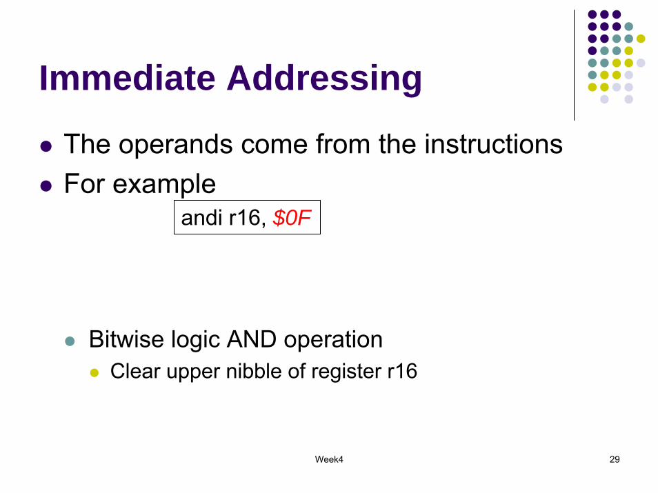
Immediate Addressing
The operands come from the instructionsFor example
Bitwise logic AND operationClear upper nibble of register r16
andi r16, $0F
Week4 30
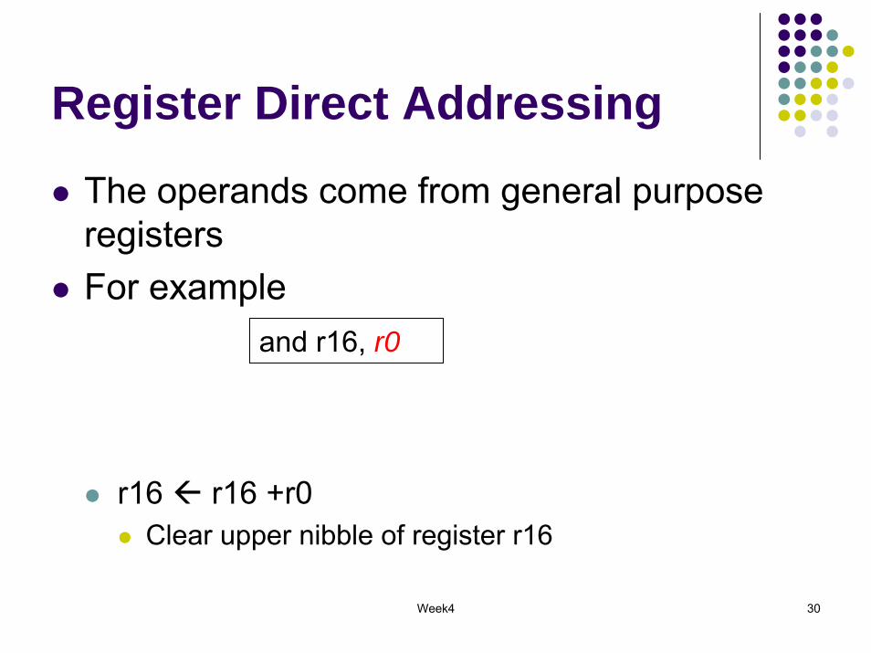
Register Direct Addressing
The operands come from general purpose registersFor example
r16 r16 +r0Clear upper nibble of register r16
and r16, r0

Week4 31
Register Direct Addressing
The operands come from I/O registersFor example
in r25, PINA-- r25 PIN A
Week4 32
Data Memory Addressing
Week4 33
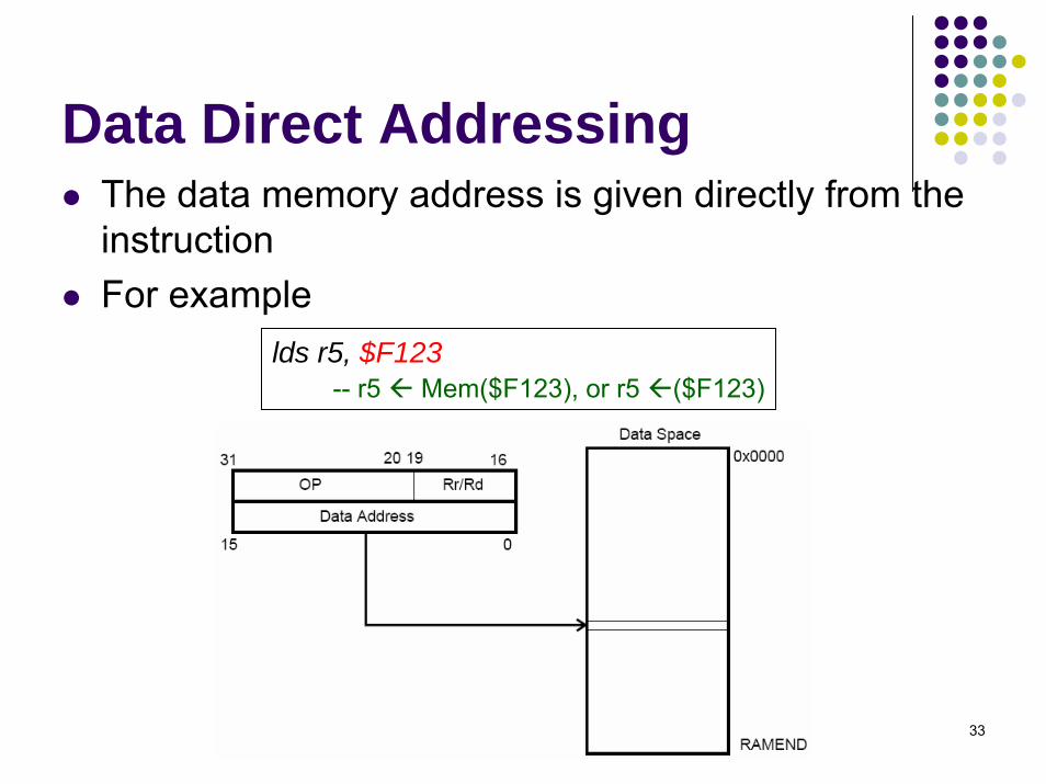
Data Direct AddressingThe data memory address is given directly from the instructionFor example
lds r5, $F123-- r5 Mem($F123), or r5 ($F123)
Week4 34
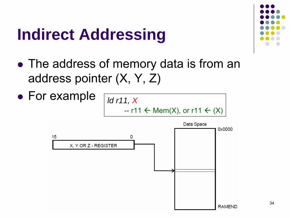
Indirect Addressing
The address of memory data is from an address pointer (X, Y, Z)For example ld r11, X
-- r11 Mem(X), or r11 (X)

Week4 35
Indirect Addressing with displacement
The address of memory data is from (Y,Z)+qFor example
std Y+10, r14-- (Y+10) r14
Week4 36
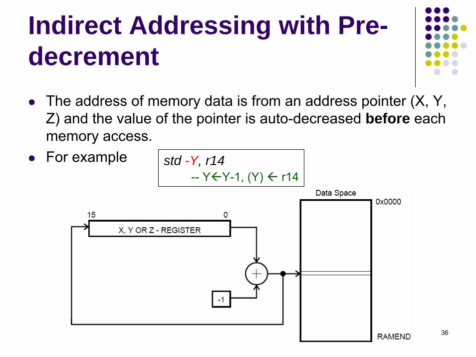
Indirect Addressing with Pre-decrement
The address of memory data is from an address pointer (X, Y, Z) and the value of the pointer is auto-decreased before each memory access.For example std -Y, r14
-- Y Y-1, (Y) r14

Week4 37
Indirect Addressing with Post-increment
The address of memory data is from an address pointer (X, Y, Z) and the value of the pointer is auto-increased after each memory access.For example std Y+, r14
-- (Y) r14, Y Y+1

Week4 38
Program Memory Addressing
Week4 39
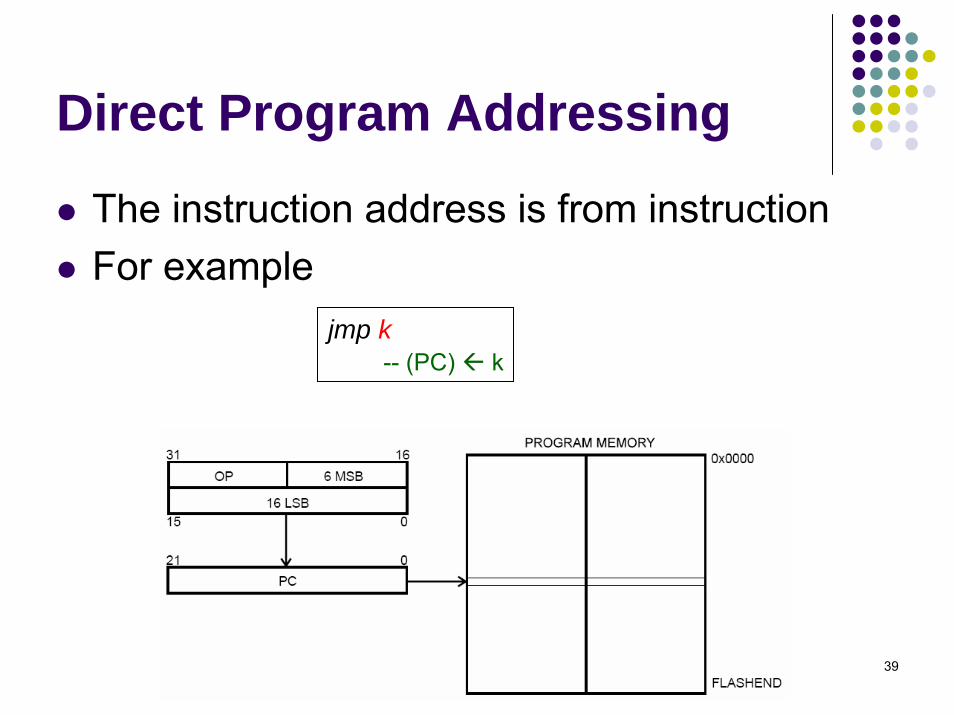
Direct Program Addressing
The instruction address is from instructionFor example
jmp k-- (PC) k

Week4 40
Relative Program Addressing
The instruction address is PC+k+1For example rjmp k
-- (PC) (PC)+k+1

Week4 41
Indirect Memory Addressing
The instruction address is implicitly stored in Z register icall
-- PC(15:0) (Z), PC(21:16) 0
Week4 42
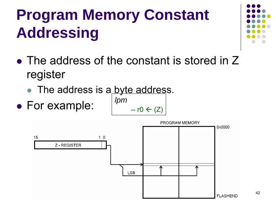
Program Memory Constant Addressing
The address of the constant is stored in Z register
The address is a byte address.For example: lpm
-- r0 (Z)
Week4 43
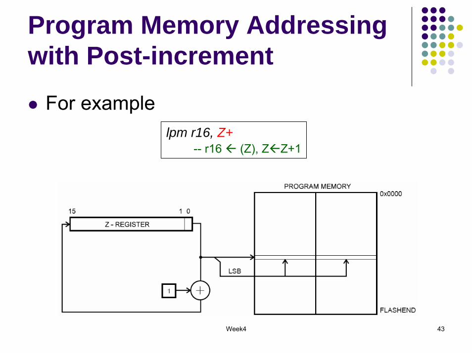
Program Memory Addressing with Post-increment
For examplelpm r16, Z+
-- r16 (Z), Z Z+1
Week4 44
AVR Programming
Refer to the online AVR Instruction Set documentation for the complete list of AVR instructions
http://www.cse.unsw.edu.au/~cs9032/refs/AVR-Instruction-Set.pdf
The rest of the lecture coversProgramming to implement some basic constructs with examples
Week4 45
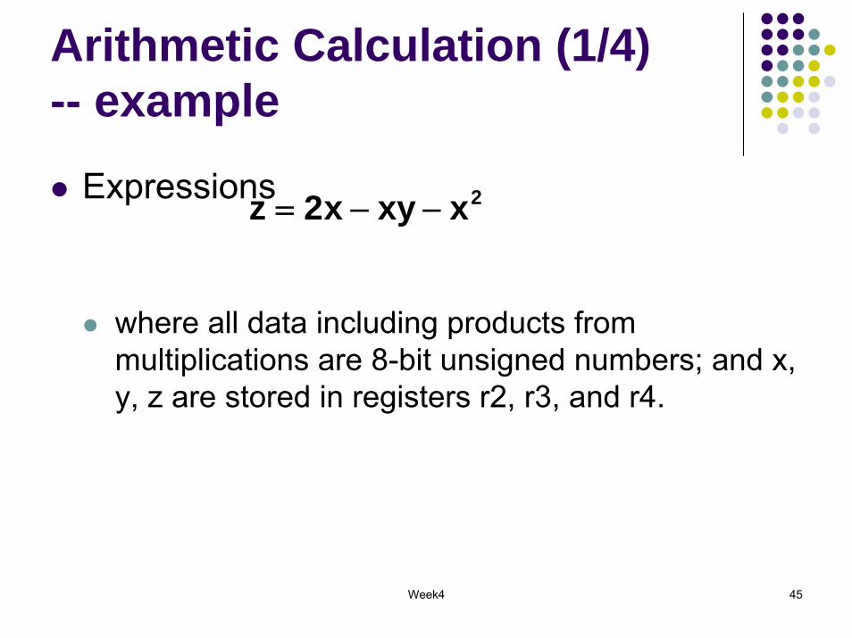
Arithmetic Calculation (1/4) -- example
Expressions
where all data including products from multiplications are 8-bit unsigned numbers; and x, y, z are stored in registers r2, r3, and r4.
2xxyx2z −−=

Week4 46
What instructions do you need?
submulldimov
Week4 47
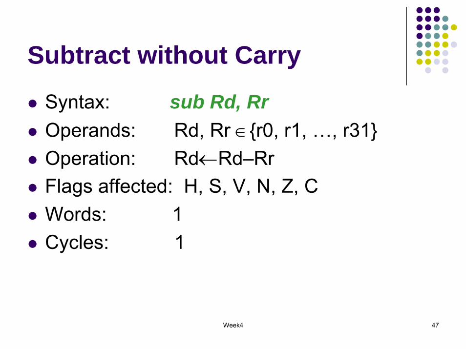
Subtract without Carry
Syntax: sub Rd, RrOperands: Rd, Rr ∈{r0, r1, …, r31}Operation: Rd←Rd–RrFlags affected: H, S, V, N, Z, CWords: 1Cycles: 1

Week4 48
Multiply Unsigned
Syntax: mul Rd, RrOperands: Rd, Rr ∈{r0, r1, …, r31}Operation: r1:r0←Rr*Rd
(unsigned←unsigned * unsigned )Flags affected: Z, C
C is set if bit 15 of the result is set; cleared otherwise.
Words: 1Cycles: 2

Week4 49
Load ImmediateSyntax: ldi Rd, kOperands: Rd∈{r16, …, r31}, 0 ≤ k ≤255 Operation: Rd←kFlag affected: NoneWords: 1 Cycles: 1Encoding: 1110 kkkk dddd kkkkExample:
ldi r16, $42 ; Load $42 to r16

Week4 50
Copy Register
Syntax: mov Rd, RrOperands: Rd, Rr ∈{r0,r1,…,r31} Operation: Rd←RrFlag affected: NoneWords: 1 Cycles: 1
Week4 51
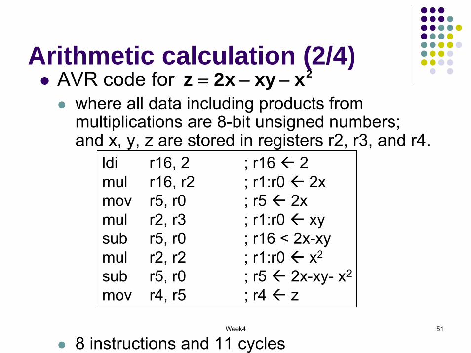
Arithmetic calculation (2/4)AVR code for
where all data including products from multiplications are 8-bit unsigned numbers; and x, y, z are stored in registers r2, r3, and r4.
8 instructions and 11 cycles
2xxyx2z −−=
ldi r16, 2 ; r16 2mul r16, r2 ; r1:r0 2xmov r5, r0 ; r5 2xmul r2, r3 ; r1:r0 xysub r5, r0 ; r16 < 2x-xymul r2, r2 ; r1:r0 x2
sub r5, r0 ; r5 2x-xy- x2
mov r4, r5 ; r4 z

Week4 52
Arithmetic calculation (3/4)Expressions
where all data including products from multiplications are 8-bit unsigned numbers; and x, y, z are stored in registers r2, r3, and r4.
2xxyx2z −−=))yx(2(xz +−=

Week4 53
What instructions do you need?
submulldimovadd
Week4 54
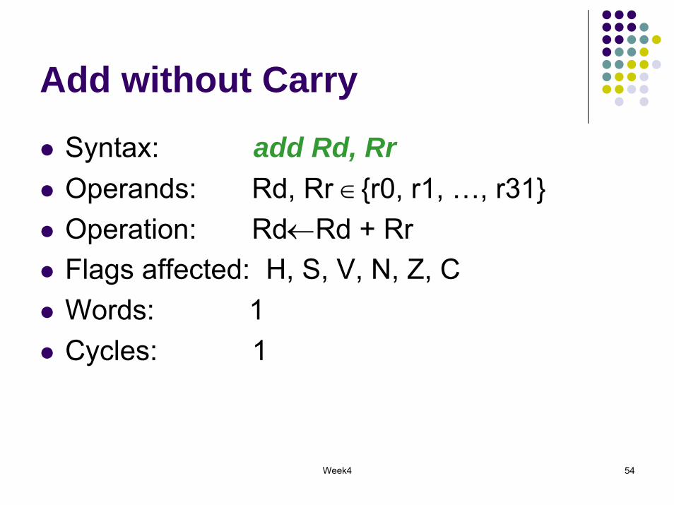
Add without Carry
Syntax: add Rd, RrOperands: Rd, Rr ∈{r0, r1, …, r31}Operation: Rd←Rd + RrFlags affected: H, S, V, N, Z, CWords: 1Cycles: 1

Week4 55
Arithmetic calculation (4/4)AVR code for
where all data including products from multiplications are 8-bit unsigned numbers; and x, y, z are stored in registers r2, r3, and r4.
6 instructions and 7 cycles
2xxyx2z −−=))yx(2(xz +−=
mov r5, r2 ; r5 xadd r5, r3 ; r5 x+yldi r16, 2 ; r16 2sub r16, r5 ; r16 < 2-(x+y)mul r2, r16 ; r1:r0 x(2-(x+y))mov r4, r0 ; r4 z
Week4 56
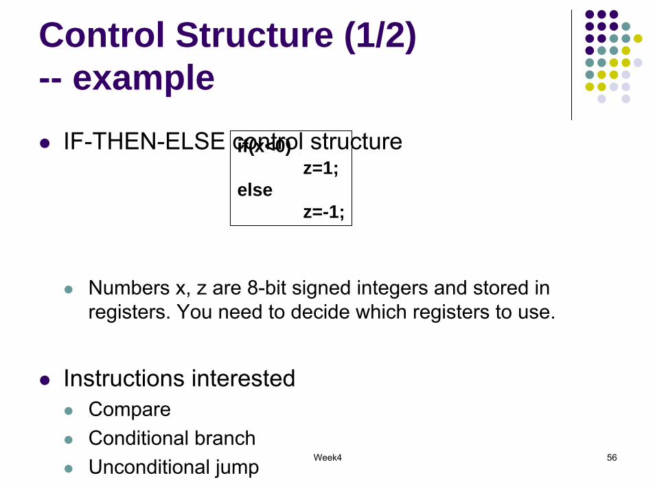
Control Structure (1/2)-- example
IF-THEN-ELSE control structure
Numbers x, z are 8-bit signed integers and stored in registers. You need to decide which registers to use.
Instructions interestedCompareConditional branchUnconditional jump
if(x<0)z=1;
elsez=-1;
Week4 57
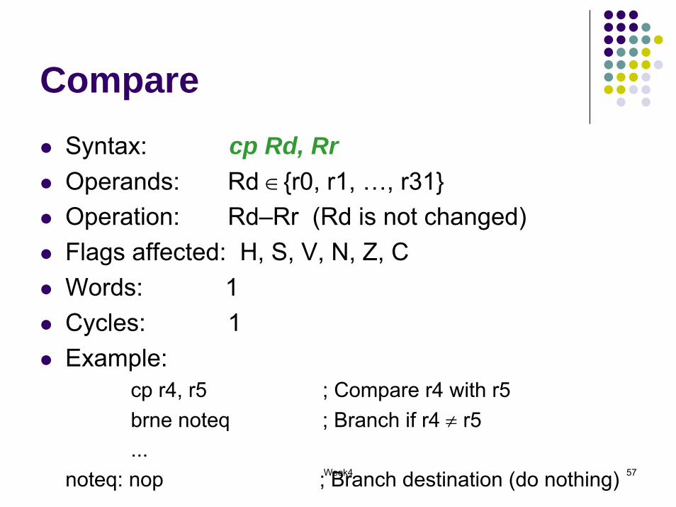
CompareSyntax: cp Rd, RrOperands: Rd ∈{r0, r1, …, r31} Operation: Rd–Rr (Rd is not changed) Flags affected: H, S, V, N, Z, CWords: 1Cycles: 1Example:
cp r4, r5 ; Compare r4 with r5brne noteq ; Branch if r4 ≠ r5...
noteq: nop ; Branch destination (do nothing)
Week4 58
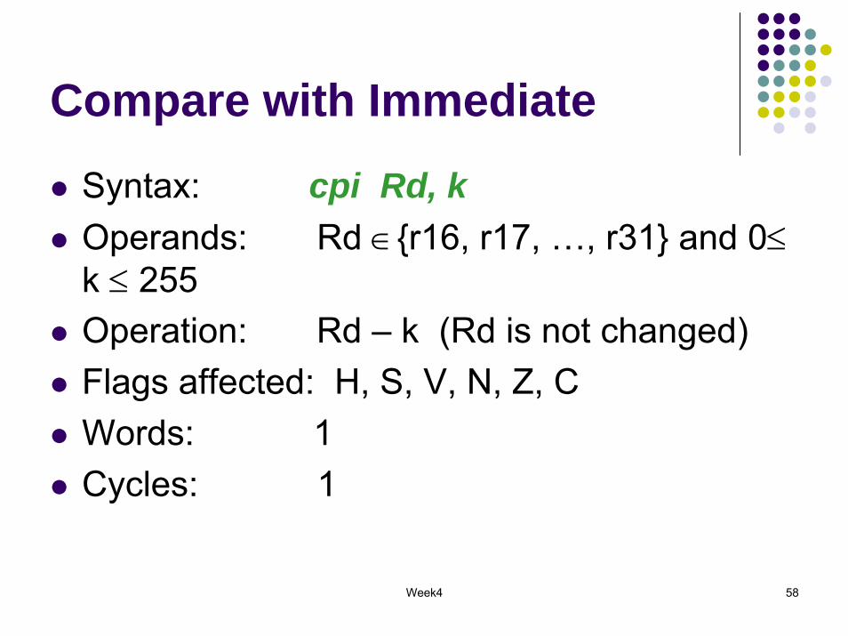
Compare with Immediate
Syntax: cpi Rd, kOperands: Rd ∈{r16, r17, …, r31} and 0≤k ≤ 255Operation: Rd – k (Rd is not changed) Flags affected: H, S, V, N, Z, CWords: 1Cycles: 1
Week4 59
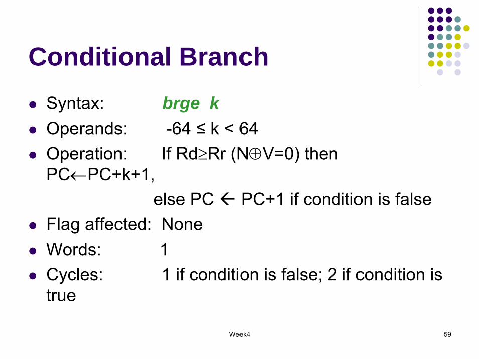
Conditional BranchSyntax: brge kOperands: -64 ≤ k < 64 Operation: If Rd≥Rr (N⊕V=0) then PC←PC+k+1,
else PC PC+1 if condition is falseFlag affected: NoneWords: 1 Cycles: 1 if condition is false; 2 if condition is true
Week4 60
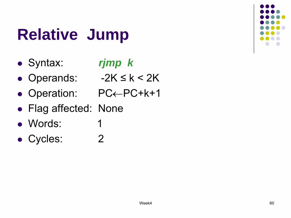
Relative JumpSyntax: rjmp kOperands: -2K ≤ k < 2K Operation: PC←PC+k+1Flag affected: NoneWords: 1 Cycles: 2
Week4 61
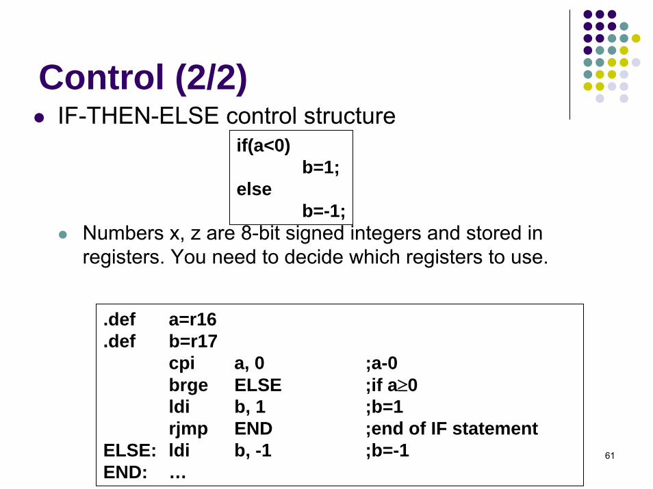
Control (2/2) IF-THEN-ELSE control structure
Numbers x, z are 8-bit signed integers and stored in registers. You need to decide which registers to use.
.def a=r16
.def b=r17cpi a, 0 ;a-0brge ELSE ;if a≥0ldi b, 1 ;b=1rjmp END ;end of IF statement
ELSE: ldi b, -1 ;b=-1END: …
if(a<0)b=1;
elseb=-1;
Week4 62
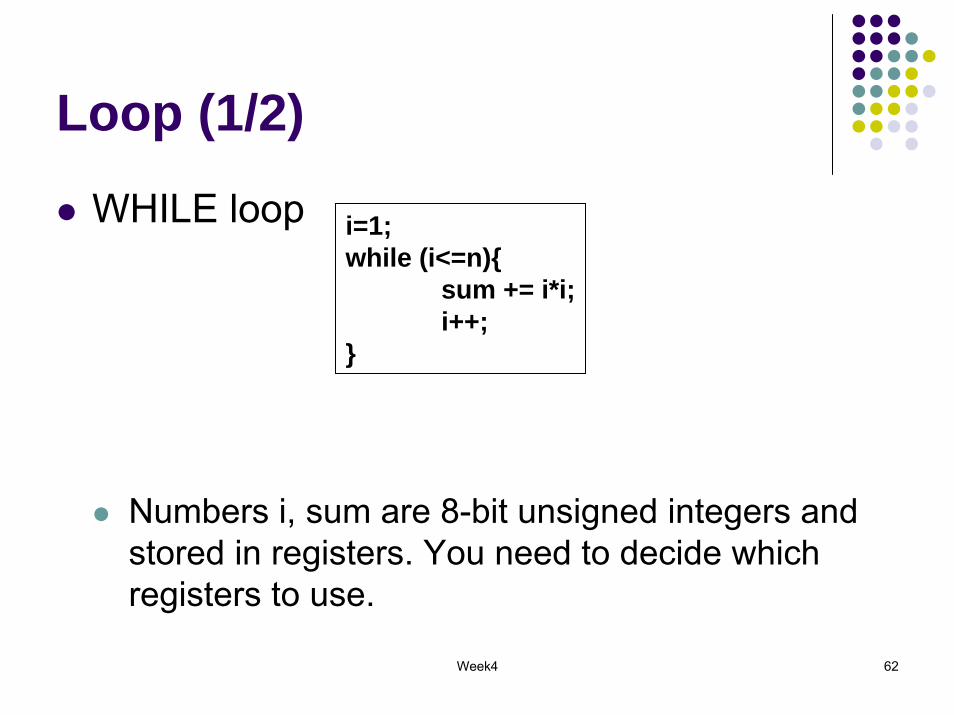
Loop (1/2)
WHILE loop
Numbers i, sum are 8-bit unsigned integers and stored in registers. You need to decide which registers to use.
i=1;while (i<=n){
sum += i*i;i++;
}

Week4 63
Loop (2/2)
WHILE loop.def i = r16.def n = r17.def sum = r18
ldi i, 1 ;initializeclr sum
loop:cp n, ibrlo endmul i, iadd sum, r0inc irjmp loop
end:rjmp end
Week4 64
Homework
1. Refer to the AVR Instruction Set documentation (available at http://www.cse.unsw.edu.au/~COMP9032/refs/AVR-Instruction-Set.pdf). Study the following instructions:
Arithmetic and logic instructionsadd, adc, adiw, sub, subi, sbc, sbci, subiw, mul, muls, mulsuand, andi, or, ori, eorcom, neg

Week4 65
Homework
1. Study the following instructions (cont.)Branch instructions
cp, cpc, cpirjmpbreq, brnebrge, brltbrsh, brlo
Data transfer instructionsmovldi, ld, st
Week4 66
Homework
2. Implement the following functions with AVR assembly language1) 2-byte addition2) 2-byte multiplication
3. Inverse a string of ten characters that is stored in the registers r0~r9; and store the inversed string in registers r10~r19
Week4 67
Homework
4. Translate the following if-then-else statement, where x is an 8-bit unsigned integer.
if(x<0)z=1;
elsez=255;
Week4 68
Reading Material
AVR Instruction Set online documentationInstruction Set NomenclatureI/O RegistersThe Program and Data AddressingArithmetic instructions, program control instructions
![AVR - dl.melec.irdl.melec.ir/download/pdf/AVR/CodeVision-Fusebit[Melec.ir].pdf · AVR AVR AVR AVR 01 CodeVision CKSEL3..0 Device Clocking Option CKSEL3..0 External Crystal/Ceramic](https://static.fdocuments.in/doc/165x107/5cf6e10d88c99387248bfc0e/avr-dlmelecirdlmelecirdownloadpdfavrcodevision-fusebitmelecirpdf.jpg)