AVR -Based Uni-Directional Radio Starter Kit Sheets/Atmel PDFs/STK511 Starter... · ¾Align signal...
16
® STK511 AVR ® -Based Uni-Directional Radio Starter Kit
Transcript of AVR -Based Uni-Directional Radio Starter Kit Sheets/Atmel PDFs/STK511 Starter... · ¾Align signal...
®
STK511AVR®-Based Uni-Directional
Radio Starter Kit
18-Mrz-05 2
®
STK511
Outline
IntroductionKit ContentsReceiver Application BoardReceiver Interface Board
Stand-alone OperationOperation with STK500
Transmitter Application BoardSystem Setup
General SetupDemo Setup – HardwareDemo Setup – SoftwareDemo Receiver ConfigurationDemo Transmitter Configuration
Running the DemoConclusion
18-Mrz-05 3
®
STK511
Introduction
UHF radio covers 315, 434, 868 and 915 MHzSupports “intelligent” receiver ICsAtmel reference design receiver uses AVR® in STK500Atmel reference design transmitter uses ATtiny13
Supports 8-pin TSSOP PLL transmitters ICsASK or FSK transmission is pushbutton selectable
Receiver Interface BoardSupports stand-alone receiver operationQuickly programs configuration registers
OPMODELIMIT
Doubles as an expansion card for STK500Enables quick prototype developmentSample software for STK500 included
18-Mrz-05 4
®
STK511
Kit Contents
STK511 Receiver Interface Board (IFB)RF Receiver Application Board (RAB) – one of the following:
T5743 (315/433.92 MHz)T5760 (868 MHz)T5761 (915 MHz)
RF Transmitter Application Board (TAB) – one of the following:Tiny13 + T5750 (868/915MHz)Tiny13 + T5753 (315MHz)Tiny13 + T5754 (433.92MHz)
CD containing sample software and related documentsAntenna
Transmitter uses integrated PCB traceReceiver uses external monopole whip
18-Mrz-05 5
®
STK511
Receiver Application Board
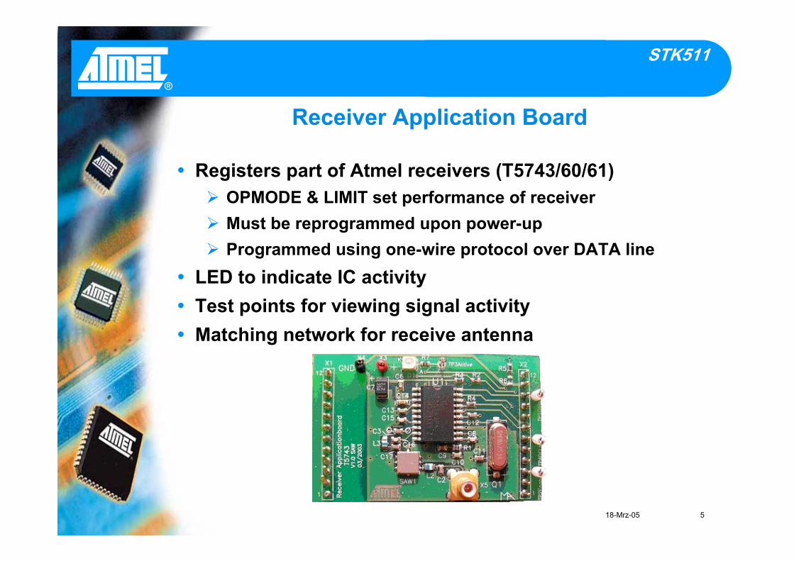
Registers part of Atmel receivers (T5743/60/61)OPMODE & LIMIT set performance of receiverMust be reprogrammed upon power-upProgrammed using one-wire protocol over DATA line
LED to indicate IC activityTest points for viewing signal activityMatching network for receive antenna
18-Mrz-05 6
®
STK511
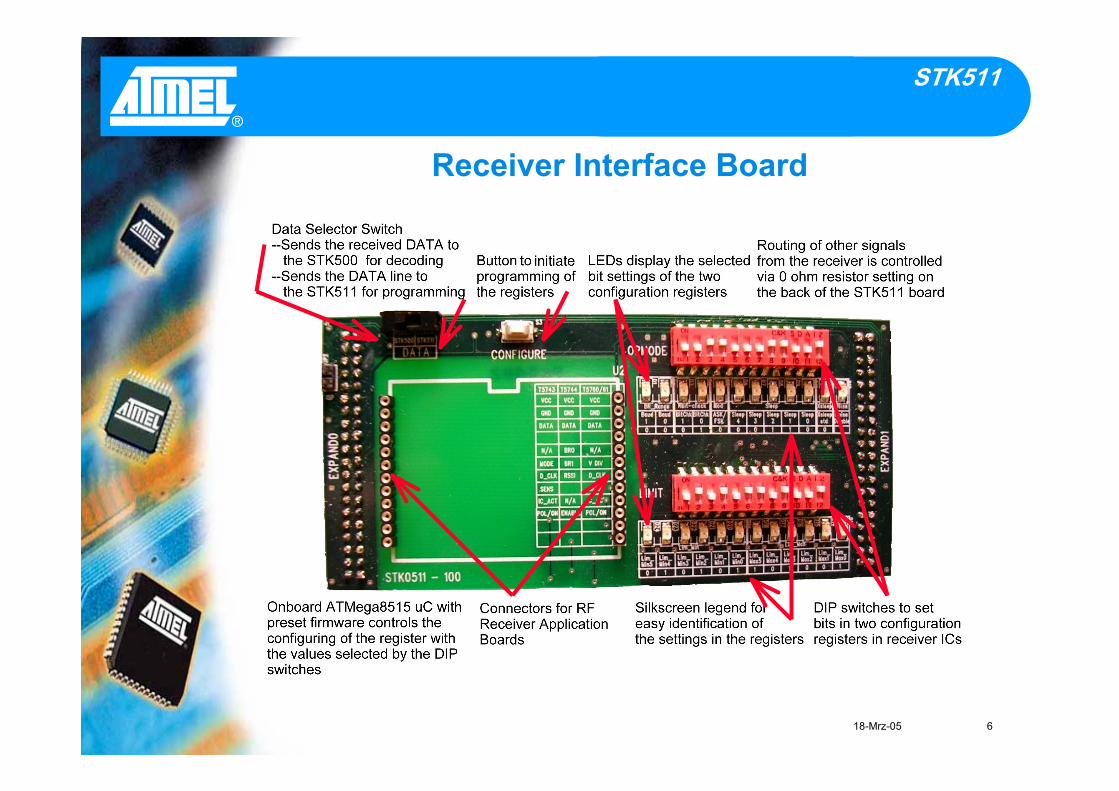
Receiver Interface Board
18-Mrz-05 7
®
STK511
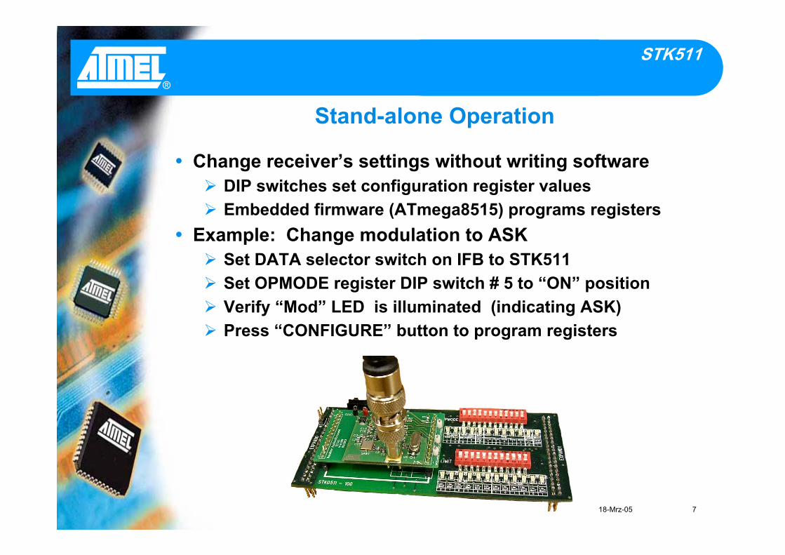
Stand-alone Operation
Change receiver’s settings without writing softwareDIP switches set configuration register valuesEmbedded firmware (ATmega8515) programs registers
Example: Change modulation to ASKSet DATA selector switch on IFB to STK511Set OPMODE register DIP switch # 5 to “ON” positionVerify “Mod” LED is illuminated (indicating ASK)Press “CONFIGURE” button to program registers
18-Mrz-05 8
®
STK511
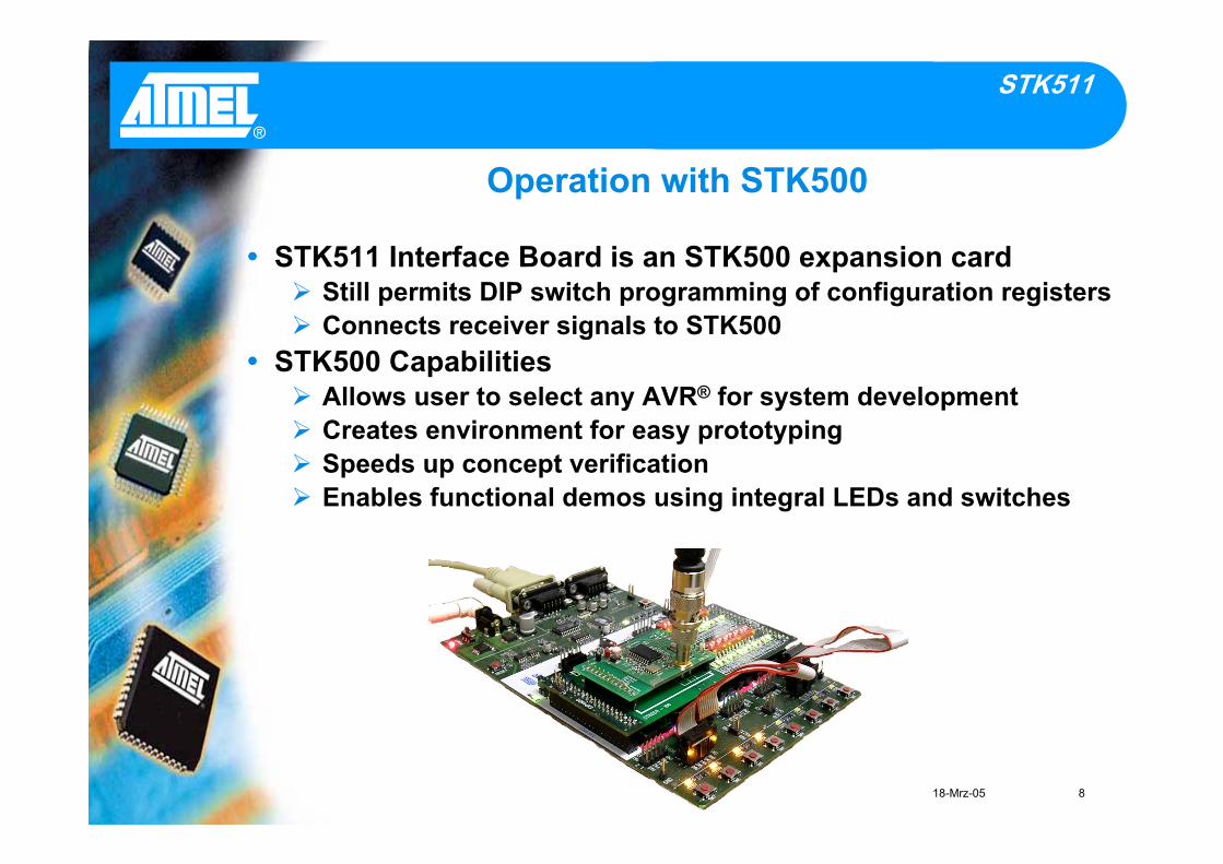
Operation with STK500
STK511 Interface Board is an STK500 expansion cardStill permits DIP switch programming of configuration registersConnects receiver signals to STK500
STK500 CapabilitiesAllows user to select any AVR® for system developmentCreates environment for easy prototypingSpeeds up concept verificationEnables functional demos using integral LEDs and switches
18-Mrz-05 9
®
STK511
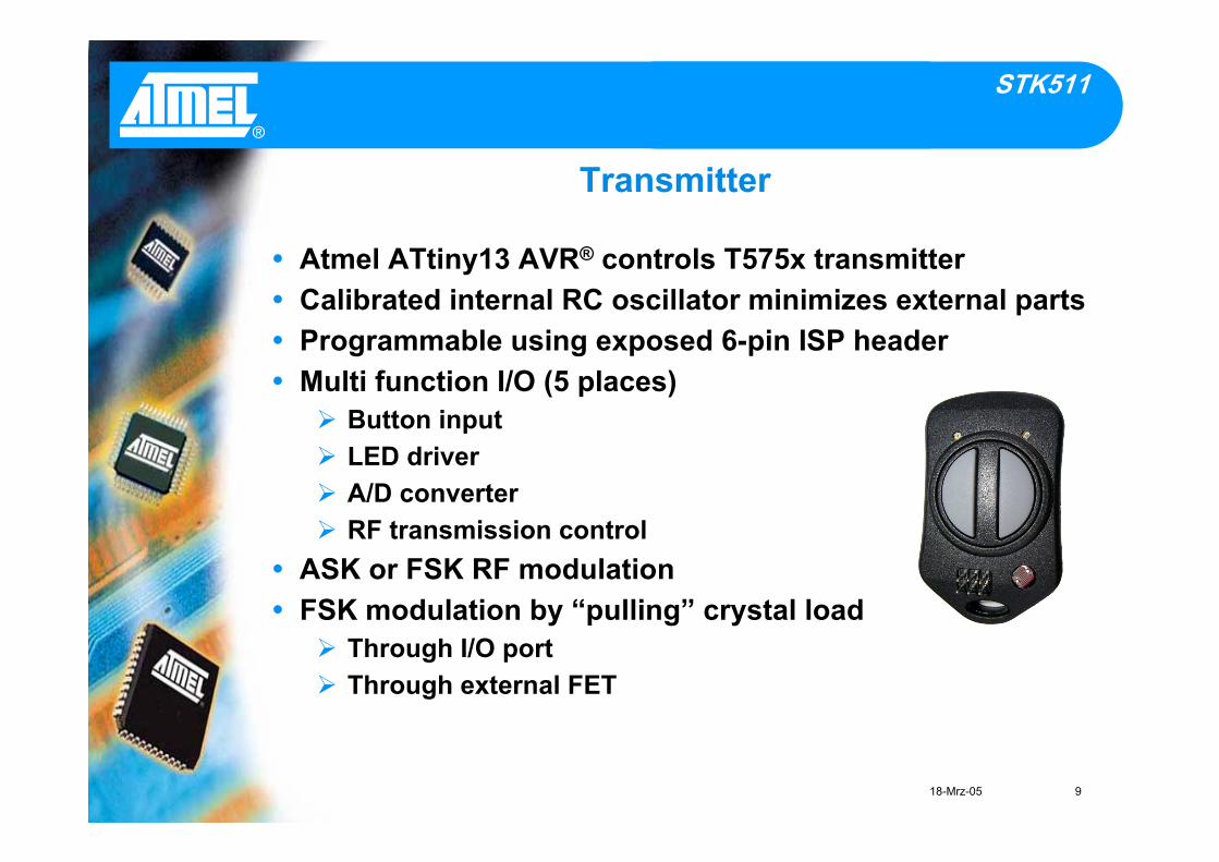
Transmitter
Atmel ATtiny13 AVR® controls T575x transmitterCalibrated internal RC oscillator minimizes external partsProgrammable using exposed 6-pin ISP headerMulti function I/O (5 places)
Button inputLED driverA/D converterRF transmission control
ASK or FSK RF modulationFSK modulation by “pulling” crystal load
Through I/O portThrough external FET

18-Mrz-05 10
®
STK511
General Setup
Stand-alone Operation (RAB to IFB Assembly)Align signal pins of RAB near DIP switches on IFBAlign “+” and “GND” test points of RAB near DATAswitch on IFBInsert RAB into 12-pin header connectors on IFBApply +5V supply to “+” and “GND” test points of RAB
Operation with STK500 (RAB/IFB Assembly to STK500)Align EXPAND0 and EXPAND1 pin headers of IFB & STK500Insert IFB into STK500 (don’t pinch ribbon cables!)Use VTARGET of STK500 sourced through EXPAND0/1
18-Mrz-05 11
®
STK511
Demo Setup - Hardware
Verify AT90S8515 AVR® in 40-pin SCKT3000D3(red silkscreen)Short VTARGET jumper setting on STK500Verify cable connections
DB9: From RS232 CTRL and host PC serial port6-wire ribbon: Between SPROG3 and ISP6PIN headers10-wire ribbon: From LEDS header to PORTC header
Connect RAB/IFB Assembly to STK500Apply +12V with supplied connector
18-Mrz-05 12
®
STK511
Demo Setup - Software
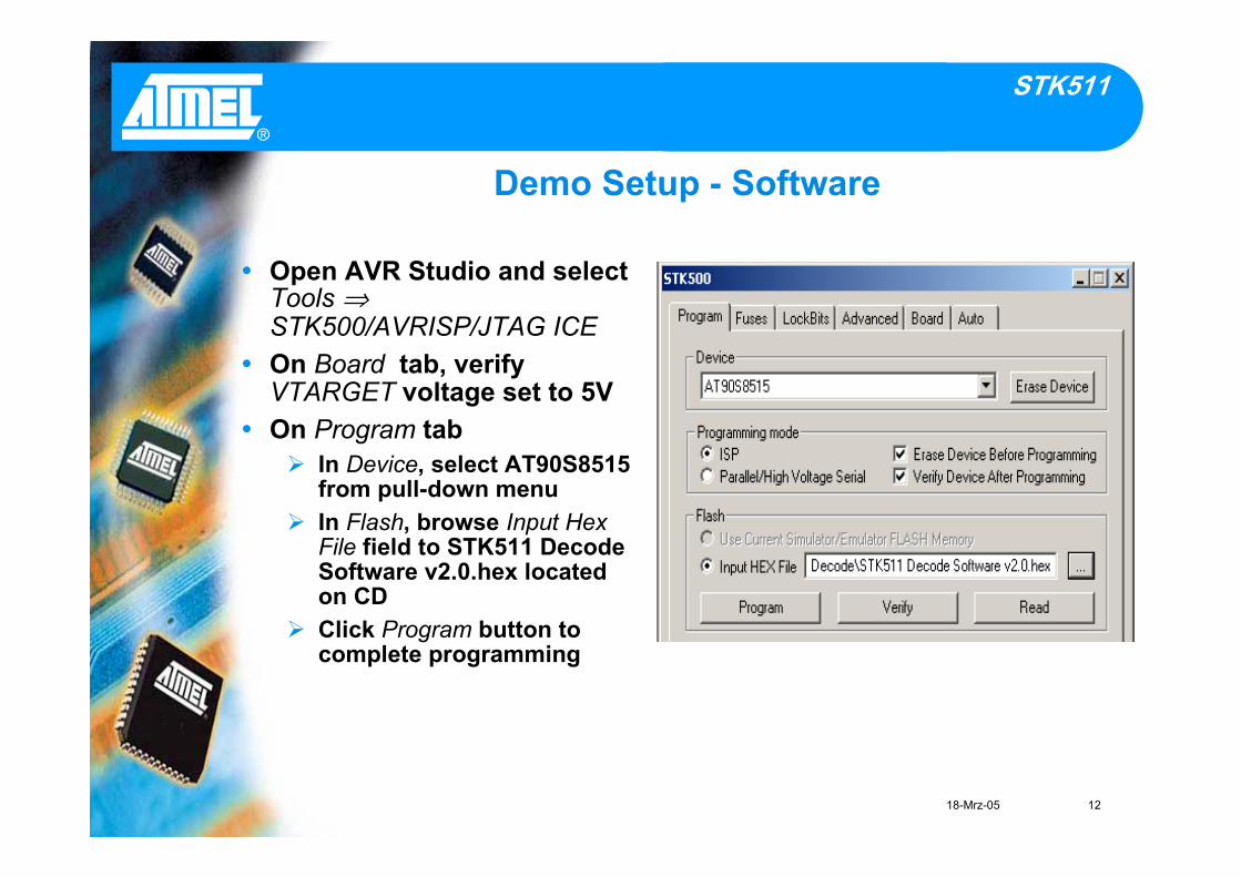
Open AVR Studio and selectTools ⇒STK500/AVRISP/JTAG ICEOn Board tab, verifyVTARGET voltage set to 5VOn Program tab
In Device, select AT90S8515from pull-down menuIn Flash, browse Input HexFile field to STK511 DecodeSoftware v2.0.hex locatedon CDClick Program button tocomplete programming
18-Mrz-05 13
®
STK511
Demo Receiver Configuration
Set DATA selector switch on IFB to STK511Set DIP switches as follows (SW#1 …SW#12):
OPMODE register: 000100011001LIMIT register: 010101101001Default values printed on board silkscreen below DIP switch
Press “CONFIGURE” button to write values into registersSet DATA selector switch on IFB to STK500
18-Mrz-05 14
®
STK511
Shipped in low current “sleep” modePeriodic RF transmission starts upon button release
LED(s) blinks on RF activityRF contains ambient light level data
Toggle ASK/FSK by pressing buttons simultaneouslyFSK selected if both LEDs blinkASK selected if only one LED blinks
Reverts to “sleep” mode after 30 secondsToggle between fast/slow update rate
Press right button for ¼-second update intervalPress left button for 8-second update interval
Demo program highlights ATtiny13 A/D converter
Demo Transmitter Configuration

18-Mrz-05 15
®
STK511
Running the Demo
Light intensity shown as LED bar graph on STK500
Varying ambient light level changes LED bar graphAs light gets brighter, more LEDs turn on
Darkness corresponds to all LEDs off
¼-second RF transmit interval yields real-time updates
“DATA” test point on RAB (also PB4 on STK500)View demodulated RF data under normal operation
View programming data when configuring the receiverregisters
18-Mrz-05 16
®
STK511
Conclusion
STK511 is a …Flexible development system compatible with the STK500Quality support tool that supports many Atmel devices
STK511 enables …Easy chipset evaluation of Atmel's uni-directional RF radiosFast design and verification of AVR®-based RF radios
STK511 kits are available todayGet yours now!
Order numbersATAKSTK511- 3 Operates at 315 MHzATAKSTK511- 4 Operates at 434 MHzATAKSTK511- 8 Operates at 868 MHzATAKSTK511- 9 Operates at 915 MHz


![AVR - dl.melec.irdl.melec.ir/download/pdf/AVR/CodeVision-Fusebit[Melec.ir].pdf · AVR AVR AVR AVR 01 CodeVision CKSEL3..0 Device Clocking Option CKSEL3..0 External Crystal/Ceramic](https://static.fdocuments.in/doc/165x107/5cf6e10d88c99387248bfc0e/avr-dlmelecirdlmelecirdownloadpdfavrcodevision-fusebitmelecirpdf.jpg)