AVIONICS ISOLATION DESIGN GUIDELINES - Vibrationdata
53
1 AVIONICS ISOLATION DESIGN GUIDELINES Revision C By Tom Irvine Email: [email protected] July 16, 2009 Introduction The purpose of this report is to develop guidelines and simple equations for avionics isolator design. Launch vehicle avionics components contain sensitive electronic parts that my fail when subjected to shock and vibration excitation during flight. A crystal oscillator may shatter or a solder joint may fail, for example. The failure mode may be ultimate stress, yielding, buckling, fatigue, relative displacement, or loss-of-clearance. Fatigue is usually the most critical mode for vibration. Avionics components may be mounted via isolators to reduce the shock and vibration energy transmitted from the mounting location to the component itself. There are certain exceptions, however, as described in Appendix D. The isolators are typically made from a rubber-like elastomeric or thermoplastic material. Elastomeric materials are considered as incompressible since their volume tends to remains constant regardless of the load. Nevertheless, the elastomeric isolator’s deflection depends on the load. The isolator’s edges bulge outward to maintain the constant volume during loading. Ideally, the isolators render the component as a single-degree-of-freedom (SDOF) system with respect to each axis. The isolators also lower the component’s natural frequency. These are the two most important benefits of isolation. The isolators may also provide damping. This is an important, although secondary, benefit for launch vehicle components. Damping reduces the amplitude of resonant vibration by converting a portion of the energy into low-grade heat. Internal friction is the mechanism for this energy conversion. This is hysteretic damping, although it can be modeled as viscous damping for calculation purposes. A single-degree-of-freedom system attenuates energy above 2 times its natural frequency. The isolators thus filter out high-frequency shock and vibration energy. As a trade-off, some amplification occurs at the isolated system’s natural frequency. Ideally, there is sufficient damping to minimize this amplification. Relative displacement may be another trade-off. Nevertheless, isolation is almost always a good practice for most avionics components.
Transcript of AVIONICS ISOLATION DESIGN GUIDELINES - Vibrationdata

1
AVIONICS ISOLATION DESIGN GUIDELINES Revision C
By Tom Irvine Email: [email protected] July 16, 2009 Introduction The purpose of this report is to develop guidelines and simple equations for avionics isolator design. Launch vehicle avionics components contain sensitive electronic parts that my fail when subjected to shock and vibration excitation during flight. A crystal oscillator may shatter or a solder joint may fail, for example. The failure mode may be ultimate stress, yielding, buckling, fatigue, relative displacement, or loss-of-clearance. Fatigue is usually the most critical mode for vibration. Avionics components may be mounted via isolators to reduce the shock and vibration energy transmitted from the mounting location to the component itself. There are certain exceptions, however, as described in Appendix D. The isolators are typically made from a rubber-like elastomeric or thermoplastic material. Elastomeric materials are considered as incompressible since their volume tends to remains constant regardless of the load. Nevertheless, the elastomeric isolator’s deflection depends on the load. The isolator’s edges bulge outward to maintain the constant volume during loading. Ideally, the isolators render the component as a single-degree-of-freedom (SDOF) system with respect to each axis. The isolators also lower the component’s natural frequency. These are the two most important benefits of isolation. The isolators may also provide damping. This is an important, although secondary, benefit for launch vehicle components. Damping reduces the amplitude of resonant vibration by converting a portion of the energy into low-grade heat. Internal friction is the mechanism for this energy conversion. This is hysteretic damping, although it can be modeled as viscous damping for calculation purposes. A single-degree-of-freedom system attenuates energy above 2 times its natural frequency. The isolators thus filter out high-frequency shock and vibration energy. As a trade-off, some amplification occurs at the isolated system’s natural frequency. Ideally, there is sufficient damping to minimize this amplification. Relative displacement may be another trade-off. Nevertheless, isolation is almost always a good practice for most avionics components.

2
Assumptions
1. Each isolator behaves as a mass-less linear spring. 2. Potential high frequency, standing wave effects in isolators are not considered. 3. Each displacement is given terms of zero-to-peak.
Mounting Configuration Isolator mounts are used to break metal-to-metal contact between the avionics component mounting foot and the vehicle mounting structure. An example is shown in Figure 1 which is representative of E-A-R grommets. Figure 1. Typical Isolator Configuration The bolt may be a shoulder bolt in order to control the initial compression of the isolator. The initial static deflection is typically 5% to 15%, depending on the vendor’s recommendation. The isolator may be a two-piece grommet with a ring and bushing. This approach is particularly suitable if the foot has a non-standard thickness. Usually, four isolator grommets are used for mounting an avionics component. The isolators are mounted in parallel with one isolator at each corner. Note that small components, with mass less than say 3 lbm, should be mounted via an isolated base plate, where the base plate serves as ballast mass. A base plate may also be required if the component’s feet are too small to accommodate the isolators directly. There are other possible mounting configurations. For example, an avionics component may be hardmounted to a bracket. The bracket is then mounted to a bulkhead, skin, or another structure via isolators.
Bolt Washer
Isolator Grommet
Avionics Box Foot
Mounting Surface (locking insert not shown)
Avionics Box

3
Lord Isolators Properties The most common Lord isolator model for avionics is 156APLQ-8. This isolator’s static stiffness is 56 lbf/in. The isolator’s dynamic stiffness is 80 lbf/in. The allowable deflection is 0.25 inch lateral and 0.38 inch axial. The temperature range is between 15°F and 100°F. The average mass per isolator must be between 0.75 lbm and 2.25 lbm. The stiffness, deflection and load values are taken from Reference 1. Further data is given in Appendix B. E-A-R Isolator Properties The most common E-A-R isolator model for avionics is B-434/R-444. This model number refers to the geometry. This model is available in several different elastomeric materials. The stiffness depends on the material, temperature, and load factor. The materials are color-coded. The most common material is C-1002, which is blue. The upper temperature limit is 160°F. The lower temperature limit depends on the material. The lower limit is 45°F for the C-1002 material. The “corrected stiffness” of this isolator is typically 600 to 1200 lbf/in. The stiffness is very sensitive to temperature. A sample stiffness calculation is given in Appendix A. An Isolated Avionics Component as a Single-degree-of-freedom System Consider the single-degree-of-freedom system in Figure 2.
Figure 2.
m
k c
x
y

4
where
M is the mass
C is the viscous damping coefficient
K is the stiffness
X is the absolute displacement of the mass
Y is the base input displacement
The translational natural frequency fn of the system is
m
k
2
1fn
(1)
The units in equation (1) must be consistent. An alternate formula is
stx
G
2
1fn
(1)
where G is the acceleration of gravity and stx is the static deflection.
Let K be the stiffness in (lbf/in). Let W be the weight in lbs. The natural frequency in units of Hz is
W
K13.3fn (2)
Equations (1) and (2) can be used as a simple calculation of the natural frequency of an isolated avionics component. This assumes that the avionics component itself is a rigid body. Important Note: The stiffness term in each equation is the total stiffness of all of the isolators. The total stiffness is the sum of the individual stiffness values when the isolators are mounted in

5
parallel, which is the usual case for avionics components. This is not true, however, when the isolators are mounted in series. The calculation should be performed for translational motion in each of three orthogonal axes. The resulting natural frequencies are valid only if the degrees-of-freedom are uncoupled, however. Only one calculation is required if the isolator is “isoelastic,” such that the axial stiffness is equal to the radial stiffness. As a further note, the natural frequency is independent of the excitation method. As an example, consider a 5 lbm box is to be mounted via four isolators. The individual isolator stiffness is 80 lbf/in, in each axis. The total stiffness is 320 lbf/in. The translational natural frequency is
lbm5
in/lbf32013.3fn (3)
Hz25fn (4)

6
0.01
0.1
1
10
100
0.1 0.2 0.5 1 2 5 8
Q = 20Q = 10Q = 5
FREQUENCY RATIO ( f / fn)
AM
PLI
FIC
AT
ION
(G
/ G
)
TRANSFER MAGNITUDE SDOF SUBJECTED TO BASE EXCITATION
Figure 3.
The fundamental principle of isolation theory is represented by the transfer magnitude curves in Figure 3. The transfer magnitude equation is given in Appendix C. The frequency ratio is the ratio of the base excitation frequency divided by the SDOF system’s natural frequency. The base excitation is amplified if the frequency ratio is less than 2. The excitation is attenuated if the ratio is greater than 2. As a rule-of-thumb, the natural frequency of the mounting system should be less than or equal to one-third of the excitation frequency. Assume that an isolated system has a natural frequency of 25 Hz with an amplification factor of Q=5. It is subjected to a sinusoidal base input of 100 G at 200 Hz.

7
The frequency ratio is
(f / fn) = (200 Hz / 25 Hz ) = 8 (5) The corresponding amplification factor is 0.03, as shown in Figure 3 for the Q=5 curve. Thus, the response acceleration is
( 100 G) ( 0.03 ) = 3 G (6) This is a reduction of 30.5 dB. The curves in Figure 3 show that the acceleration response approaches zero as the frequency ratio approaches infinity. This suggests that the isolators should be as soft and compliant as possible. The relative displacement, however, becomes greater as the natural frequency deceases. There is thus some practical lower limit for the isolated natural frequency. This limit depends on the isolator specifications and on any clearance or alignment concerns. Relative displacement formulas and sample calculations are given later in this report. As a second case, assume that the SDOF system is rigid so that its natural frequency is many times greater than the excitation frequency. In this case, the frequency ratio approaches zero. The response is thus approximately equal to the excitation amplitude. This is a unity gain case. As a third case, assume that the natural frequency is equal to the excitation frequency. The frequency ratio is thus 1. Resonant amplification occurs. The response is equal to the excitation amplitude multiplied by the Q value. This is the worst case. An Isolated Avionics Component as a Two-degree-of-freedom System Figure 4. The circle and cross-hair symbol is the center of gravity (CG).
k2
L1 L2
k1 m g

8
Assume that the structure is statically uncoupled, such that 2L2k1L1k . Let J equal the polar moment of inertia about the center of mass. The rotational natural frequency is
J
22L2k2
1L1k
2
1fn
(7)
This is the frequency at which the component would “rock” if its center of gravity did not move vertically. Now assume that
2k1k2
k (8)
2L1LL (9)
The rotational natural frequency for this case is
J
k
2
Lfn
(10)
The stiffness term k is the total stiffness. Again, the units in these equations must be consistent. The polar moment for a typical avionics box can be modeled as shown in Figure 4. The corresponding inertia terms are shown in equations (11) through (13).

9
Figure 4. Rectangular Prism Assume that the mass CG is at the geometric center of the box.
2b2a
12
mJx (11)
2c2a
12
mJy (12)
2c2b
12
mJz (13)
Now assume that the CG is offset in the Y-Z plane from the geometric center by a distance d. The inertia about the X-axis passing through the CG is calculated via the parallel axis theorem.
2dm2b2a12
mJx
(14)
A similar calculation for the other two axes can be made via this theorem as appropriate.
b
a c
Y
XZ

10
Coupling The natural frequency equations presented throughout this report assume that the isolated avionics component is statically uncoupled, which is a desirable goal. On the other hand, the two-degree-degree-of-freedom structure is statically coupled if
2L2k1L1k , per Figure 4. If the system is coupled, each mode has a combination of rotational and translation motion. Reference 2 gives the natural frequency formulas for this case. The calculations are further complicated if the system is modeled with a full set of six-degrees-of-freedom. Some amount of coupling is likely because the avionics CG usually has a vertical offset from the plane where the isolators attach to the component or its base plate. A finite element model may be the most expedient analysis method for this case. A derivation for the natural frequencies of a three-degree-of-freedom system with coupling is given in Appendix E. The resulting method is somewhat beyond hand calculations but could be easily performed using a Matlab or C/C++ program. Cable and Tubing Mass The mass or weight values in the preceding natural frequency formulas may be increased to account for cable or tubing mass. There is no particular formula. A good approach would be to bound the problem first with a lower limit of zero added mass and then with some estimated upper limit of the total mass. Damping Units Damping is often expressed in terms of the amplification factor Q. Damping is also represented by the viscous damping ratio . Note that
2
1Q (15)
An amplification factor of Q=10 is thus equivalent to a viscous damping ratio of 0.05, or 5%. Octave Rule The difference between two frequencies is one octave if the higher frequency is twice the lower frequency.

11
Now assume that one SDOF system is to be attached to another SDOF system. A design rule-of-thumb is that the difference between the individual natural frequencies should be at least one octave. The goal is to avoid dynamic coupling of the modes. Assume that an avionics box has a circuit board with a natural frequency of 200 Hz. The box is to be mounted via isolators. The natural frequency of the isolated box should thus be less than or equal to 100 Hz per the octave rule. Further information is given in Reference 4.
Isolator Deflection The isolators must be able to withstand quasi-static and dynamic loads. The loading criteria may be in terms of an allowable isolator deflection. Note that the avionics component may “bottom out” if the isolator is overloaded. A related concern is the clearance or “sway space” between the component and adjacent structures. The clearance should be considered with respect to all sides of the component, undergoing its various peak positive and peak negative relative displacements. The following five sections give guidelines and examples for calculating the relative displacement to various loads. The calculations are typically performed only for the translational responses. This is a reasonable approach if the component is statically uncoupled. Otherwise, a finite element analysis may be required. Quasi-Static Flight Loads A quasi-static load results from the rigid-body acceleration of the launch vehicle. This acceleration is primarily in the vehicle’s thrust axis, but lateral acceleration should also be considered. A typical launch vehicle may have a peak rigid-body acceleration of 8 G in the thrust axis. This factor increases the “apparent weight” of the box. For example, a 5 lbm box subjected to a rigid-body acceleration of 8 G applies of force of 40 lbf against the isolators.

12
The isolator deflection z due to the quasi-static load is calculated via Hooke’s law.
k
Fz (16)
where
F is the force against the isolators k is the total isolator static stiffness
As an example, consider that the 5 lbm box is to be mounted via four isolators. The individual isolator static stiffness is 80 lbf/in. The total stiffness is 320 lbf/in. The resulting isolator deflection is
in/lbf320
G8lbm5z (17)
inch125.0z (18)
Again, the isolators must be capable of withstanding this deflection. Furthermore, the avionics component must maintain sufficient clearance with respect to any adjacent structure, such as a bulkhead. Note that the 5 lbm value in the preceding example is used directly in the natural frequency calculation, independent of the rigid-body acceleration. Coupled Loads The properties of the isolated avionics component including damping should be included in the coupled loads model. The acceleration and relative displacement of the component should be requested in this analysis. If the isolated component is not modeled explicitly, then calculate the shock response spectrum of all the hardmounted responses assuming Q=10. The peak response can then be calculated from the spectrum as a function of the component’s natural frequency. Shock and Vibration Flight Loads Launch vehicles have numerous shock and vibration events.

13
The shock environments include launch, motor ignition, stage separation, and shroud separation. The shock is typically specified in terms of a Shock Response Spectrum (SRS). An SRS tutorial is given in Reference 3. The vibration environment may be either broadband random or sinusoidal. Random vibration is primarily due to aerodynamic flow. Rocket motors also produce random vibration, but the resulting levels are usually relatively low except on forward and aft motor domes. The sine vibration in launch vehicles may be due to a motor pressure oscillation or to a gas generator. Apply Shock Loads & Calculate Deflections A sample SRS is shown in Figure 7.
1
10
100
1000
10000
10 100 1000 10000
NATURAL FREQUENCY (Hz)
PE
AK
AC
CE
L (G
)
SRS Q=10 SAMPLE SHOCK SPECIFICATION
Figure 7.

14
Assume a certain hardmounted component behaves as a single-degree-of-freedom system with a natural frequency of 200 Hz. The SRS curve shows that the component’s peak response is 100 G for this frequency. Now assume that the same component is mounted via isolators such that its natural frequency decreases to 40 Hz. The SRS curve shows that the component’s peak response is 20 G for the isolated configuration. The peak acceleration response is thus reduced by 14 dB. The isolator relative deflection Z can be calculated for the peak acceleration response A approximately as
2fn24
AZ
(19)
Now assume that Z is in inches and A is in units of G.
2fn
A78.9Z (20)
The relative displacement for isolated component in the example is
2)Hz40(
G2078.9Z (21)
inch12.0Z (22) Apply Sine Vibration Loads & Calculate Deflections The sine acceleration response is calculated using Figure 3. Recall the example where an isolated system has a natural frequency of 25 Hz with an amplification factor of Q=5. It is subjected to a sinusoidal base input of 100 G at 200 Hz. The response acceleration was calculated as 3 G via Figure 3. The relative displacement is calculated using a form of equation (19) that is adapted for sine vibration.

15
The relative displacement equation for sine is
2Q
2fn/f1
12fn24
AZ
(23)
where f is the base excitation frequency and fn is the natural frequency.
Now assume that Z is in inches and A is in units of G.
2Q
2fn/f1
12fn
A78.9Z
(24)
The frequency ratio for the same problem is
( f / fn ) = ( 200 Hz / 25 Hz ) = 8 (25)
25
281
12Hz25
G378.9Z
(26)
The relative displacement for the sine excitation is thus
inch025.0Z (27)
16
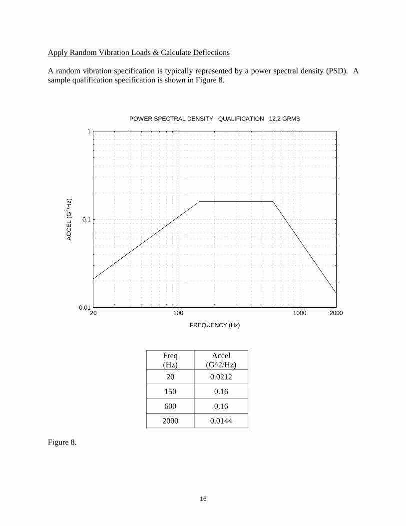
Apply Random Vibration Loads & Calculate Deflections A random vibration specification is typically represented by a power spectral density (PSD). A sample qualification specification is shown in Figure 8.
0.01
0.1
1
100 100020 2000
FREQUENCY (Hz)
AC
CE
L (G
2 /Hz)
POWER SPECTRAL DENSITY QUALIFICATION 12.2 GRMS
Freq (Hz)
Accel (G^2/Hz)
20 0.0212
150 0.16
600 0.16
2000 0.0144
Figure 8.

17
1
10
100
100 100020 2000
NATURAL FREQUENCY (Hz)
AC
CE
L (
GR
MS
)VIBRATION RESPONSE SPECTRUM Q=10
Figure 9. Assume that a component has a translational natural frequency of 200 Hz in its hardmounted configuration, with an amplification of Q=10. It is subjected to the base excitation PSD in Figure 8. The systems response can be calculated via the corresponding vibration response spectrum (VRS) in Figure 9. A further explanation of this function is given in Reference 5. The VRS shows that the 200 Hz system will have a response of 22 GRMS. The peak response is estimated at 66 G, which is the 3-sigma value. Note that the RMS value is equal to the 1-sigma value, assuming a zero mean. Now assume that the system is to be mounted via isolators so that its natural frequency is 50 Hz. For simplicity, assume that the Q value remains the same. The response is reduced to 6.4 GRMS, or 19.2 G peak, using the VRS graph. The corresponding relative displacement is 0.075 inch peak, using equation (19) or (20).
18
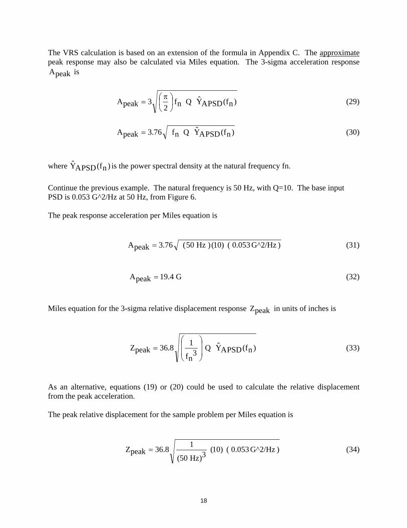
The VRS calculation is based on an extension of the formula in Appendix C. The approximate peak response may also be calculated via Miles equation. The 3-sigma acceleration response
peakA is
)nf(PSDAYQnf2
3peakA
(29)
)nf(PSDAYQnf76.3peakA (30)
where )nf(PSDAY is the power spectral density at the natural frequency fn.
Continue the previous example. The natural frequency is 50 Hz, with Q=10. The base input PSD is 0.053 G^2/Hz at 50 Hz, from Figure 6. The peak response acceleration per Miles equation is
) G^2/Hz 0.053()10()Hz50(76.3peakA (31)
G4.19peakA (32)
Miles equation for the 3-sigma relative displacement response peakZ in units of inches is
)nf(PSDAYQ3
nf
18.36peakZ
(33)
As an alternative, equations (19) or (20) could be used to calculate the relative displacement from the peak acceleration. The peak relative displacement for the sample problem per Miles equation is
) G^2/Hz 0.053()10(3)Hz50(
18.36peakZ (34)

19
) G^2/Hz 0.053()10(3)Hz50(
18.36peakZ (35)
inch076.0peakZ (36)
Summary A summary of isolator design considerations and guidelines is given in Table 1. This table was written for the MACH box but is readily applicable to other avionics components.

20
Table 1. Requirement Description Source
Technical Mechanical Volume Isolated assembly must fit within available volume.
Minimize to extent practical. Derived from requirement to accommodate as many vehicle installations as possible.
Max Deflection Assembly must not bottom out under flight loading. Derived from desire not to create additional shock load exposures.
Deflection during max dynamic loading
Total deflection under combined dynamic and static loading must not move isolator out of linear performance band
Derived from desire to avoid having to characterize dynamic performance while applying a static load.
Stress Stress margins must be acceptable using appropriate safety factors.
TM-8861E
Isolated assembly natural freq.
Should be at least 30% below excitation frequency of concern such that excitation frequency divided by natural frequency is 1.41 or greater.
Good practice.
Isolated assembly natural freq.
Should be at least one octave (2x) higher or lower than fundamental vehicle modes or mounting structure frequencies.
TM-8861E and ME 030-205A
Bracket Stiffness Natural frequency of sprung mass should be at least one octave (2x) above isolated system frequency.
TM-8861E and ME 030-205A
Environmental Resulting box levels must be less than current MACH3 ATP/QTP levels.
MACH Specification.
Mass Minimize mass to extent practical. Derived. Materials No SCC materials; low cost materials preferable. TM-8861E Electrical Grounding Provision for grounding lug required. Connector Assess Cable tie down bracket must not inhibit access to connectors. Derived from cost requirement to minimize
assembly, installation touch labor. Form factor No sharp edges. Good practice. Surface area Sufficient for harness tie down. Derived from desire to standardize tie off
methods.

21
Bibliography
Numerous isolator analyses have been written, including some with guidelines for particular configurations. A summary is given in Table 3. This list partially overlaps the Reference section on the cover page but has additional sources.
Table 3. Isolator Analysis Bibliography
009-1257 Taurus Avionics Shelf E-A-R Isolated (R-444-1/B-434-1) Transmissibility and Random Vibration, 2002
030-152 Shock Attenuation of EAR Isolators, 1999
030-205A Environments Analysis and Testing Guidelines, 2003
030-227 Lord Isolator (156APLQ-8) General Random Vibration Transmissibility, 2002
030-229 Lord Isolator (156APLQ-8) General Shock Transmissibility, 2002
030-260 Lord Isolator (156APLQ-8) Static Deflection, 2003
052-016 GCA MACH Box Isolation Bracket Design Criteria, 2004
Furthermore, the following textbooks have one or more chapters on isolation:
1. Cyril Harris, Shock and Vibration Handbook, 4th edition, McGraw-Hill, New York, 1995.
2. Beranek and Ver, Noise and Vibration Control Engineering Principles and Applications, Wiley, New York, 1992.
3. D. Steinberg, Vibration Analysis for Electronic Equipment, Third Edition, Wiley, New York, 2000.
References
1. ME File: 030-227, Lord Isolator (156APLQ-8) General Random Vibration Transmissibility, 2002.
2. ME File: 052-016, GCA MACH Box Isolation Bracket Design Criteria, 2004.
3. T. Irvine, An Introduction to the Shock Response Spectrum, Rev P, Vibrationdata, 2002.
4. D. Steinberg, Vibration Analysis for Electronic Equipment, Third Edition, Wiley, New York, 2000.
5. T. Irvine, An Introduction to the Vibration Response Spectrum, Rev C, Vibrationdata, 2000.
6. W. Kacena, M. McGrath, A. Rader; Aerospace Systems Pyrotechnic Shock Data, Vol. VI, NASA CR 116406, Goddard Space Flight Center, 1970.
22
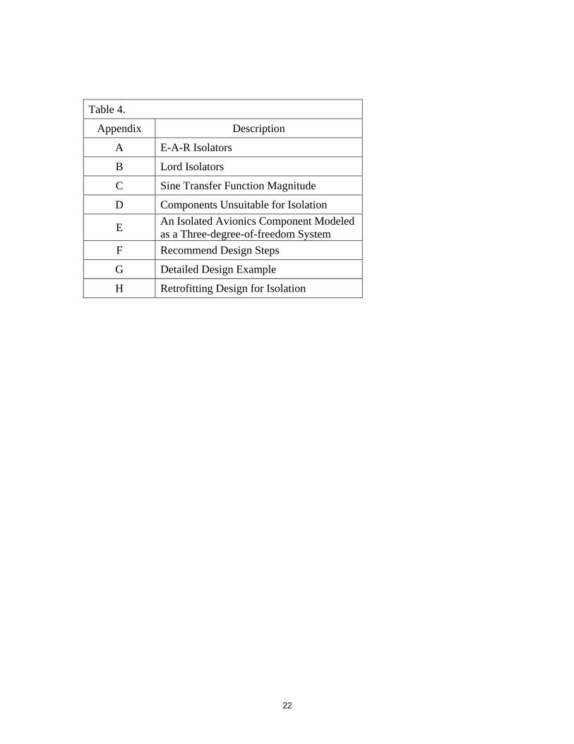
Table 4.
Appendix Description
A E-A-R Isolators
B Lord Isolators
C Sine Transfer Function Magnitude
D Components Unsuitable for Isolation
E An Isolated Avionics Component Modeled as a Three-degree-of-freedom System
F Recommend Design Steps
G Detailed Design Example
H Retrofitting Design for Isolation

23
APPENDIX A E-A-R Isolators

24
E-A-R Isodamp Grommet Natural Frequency Calculation Example
25
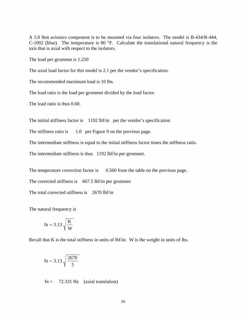
A 5.0 lbm avionics component is to be mounted via four isolators. The model is B-434/R-444, C-1002 (blue). The temperature is 80 °F. Calculate the translational natural frequency is the axis that is axial with respect to the isolators. The load per grommet is 1.250 The axial load factor for this model is 2.1 per the vendor’s specification. The recommended maximum load is 10 lbs. The load ratio is the load per grommet divided by the load factor. The load ratio is thus 0.60. The initial stiffness factor is 1192 lbf/in per the vendor’s specification The stiffness ratio is 1.0 per Figure 9 on the previous page. The intermediate stiffness is equal to the initial stiffness factor times the stiffness ratio. The intermediate stiffness is thus 1192 lbf/in per grommet. The temperature correction factor is 0.560 from the table on the previous page. The corrected stiffness is 667.5 lbf/in per grommet The total corrected stiffness is 2670 lbf/in The natural frequency is
W
K13.3fn
Recall that K is the total stiffness in units of lbf/in. W is the weight in units of lbs.
5
267013.3fn
fn = 72.331 Hz (axial translation)

26
A similar calculation could be made for each lateral axis, which is radial with respect to the isolators. The calculation is the same except that
1. The radial load factor is 1.5 2. The radial initial stiffness is 1095 lbf/in

27
APPENDIX B Lord Isolators
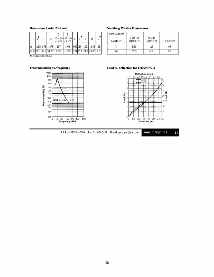
28

29
APPENDIX C Sine Transfer Function Magnitude Consider an SDOF system subject to base excitation. The ratio )(H of the acceleration response to the acceleration input is given in terms of magnitude by
nf/f,
2)2(2)21(
221)(H
(C-1)
This formula is given in Reference (3) through (5).
The ratio )(H of the relative displacement response to the acceleration input is given in terms of magnitude by
nf/f,2)2(2)21(2
n
1)(H
(C-2)

30
APPENDIX D
Components Unsuitable for Isolation Some components such as transmitters and transponders may generate significant heat energy. These components may need to be hardmounted to a bulkhead or other large structure, since the structure serves as a heat sink. Inertial navigation systems contain sensitive accelerometers and gyros. These systems typically contain their own internal isolation. Mounting the system with external isolators may interfere with the system’s operation, however. The vendor should be contacted regarding the proper mounting. The mounting surface may serve as an electrical ground plane for a given component. Isolation, however, breaks metal-to-metal contact. Electrical grounding can still be made via a ground wire. Again, isolated components may have a high relative displacement in response to low-frequency shock and vibration. This may cause an alignment or loss-of-clearance problem for certain components.

31
APPENDIX E
An Isolated Avionics Component Modeled as a Three-degree-of-freedom System Derivation The total kinetic energy is
2J
2
12y2xm2
1T
(E-1)
The total potential energy is
2cy3k2
12by2k2
12ax1k2
1V (E-2)
k 1
a
m, J
k2 k 3
b c
x
y
32
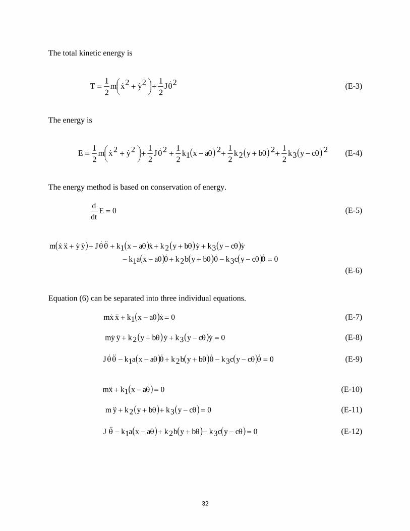
The total kinetic energy is
2J
2
12y2xm2
1T
(E-3)
The energy is
2cy3k2
12by2k2
12ax1k2
12J2
12y2xm2
1E
(E-4)
The energy method is based on conservation of energy.
0Edt
d (E-5)
0cyc3kbyb2kaxa1k
ycy3kyby2kxax1kJyyxxm
(E-6) Equation (6) can be separated into three individual equations.
0xax1kxxm (E-7)
0ycy3kyby2kyym (E-8)
0cyc3kbyb2kaxa1kJ (E-9)
0ax1kxm (E-10)
0cy3kby2kym (E-11)
0cyc3kbyb2kaxa1kJ (E-12)

33
The equations are assembled in matrix format.
0
0
0
y
x
2c3k2b2k2a1kc3kb2ka1k
c3kb2k3k2k0
a1k01k
y
x
J00
0m0
00m
(E-13) The associated eigenvalue problem is
0
J00
0m0
00m2
2c3k2b2k2a1kc3kb2ka1k
c3kb2k3k2k0
a1k01k
det
(E-14) Example An isolated avionics component has the following parameters.
m = 5 lbm (0.013 lbf sec^2/in)
J = 10.83 lbm in2 (0.028 lbf sec^2 in)
a = 0.5 inch
b = 2 inch
c = 3 in
k1 = 320 lbf/in
k2 = 160 lbf/in
k3 = 160 lbf/in
0
028.000
0013.00
00013.02
2160160160
1603200
1600320
det
(E-15)

34
The resulting natural frequencies are
f1 = 23.7 Hz
f2 = 25.0 Hz
f3 = 44.9 Hz
The corresponding mode shapes in column format are
Mode 1 Mode 2 Mode 3
6.06 -6.202 -1.31
6.06 -6.202 -1.31
1.26 0 5.84
The mode shape format is
y
x
.
Simplified Approach As a simple approximation, each “translational” natural frequency for the sample problem is
m
K
2
1fn
(E-16)
where K is the total stiffness in the particular axis.

35
sec^2/in lbf 0.013
lbm320
2
1fn
(E-17)
Hz25fn (E-18)
Similarly, the “rotational” natural frequency for the sample problem is approximately
J
2c3k2b2k2a1k
2
1fn
(E-19)
in sec^2 lbf 0.028
2)in3)(in/lbf160(2)in2)(in/lbf160(2)in5.0)(in/lbf320(
2
1fn
(E-20)
Hz2.44fn (E-21) These approximate natural frequencies have good agreement with respect to the values using the coupled model, but this simplified approach is somewhat misleading. The reason is that the mode shapes from the full calculation show that at least two-degrees-of-freedom participate in each mode.

36
APPENDIX F
Recommended steps for isolated component design are given in Table F-1. The order of the steps is not necessarily important, although some of the verification steps depend on completion of the corresponding identification steps.
Table F-1. Isolated Component Design Steps
Step Description
1 Identify mass and CG of component. Also identify mounting location.
2 Identify any cable or tubing mass.
3 Identify moments of inertia
4 Identify maximum expected temperate range.
5 Identify rigid-body acceleration loads.
6 Calculate quasi-static load against isolators.
7 Identify natural frequency of component in hardmounted configuration, particularly any circuit board natural frequencies.
8 Identify whether isolators will interfere with the component’s operation, such as the case with an INS system.
9 Identify any need for electrical grounding.
10 Identify any need for thermal grounding.
11 Identify any need for alignment.
12 Identify available volume and clearance in launch vehicle for isolated component.
13 Identify shock MPE level.
14 Identify random vibration MPE level.
15 Identify sine vibration MPE level.
37
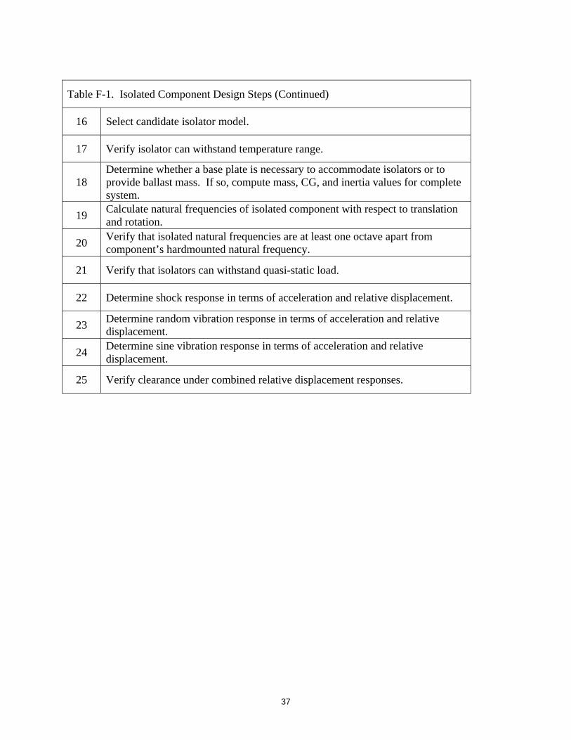
Table F-1. Isolated Component Design Steps (Continued)
16 Select candidate isolator model.
17 Verify isolator can withstand temperature range.
18 Determine whether a base plate is necessary to accommodate isolators or to provide ballast mass. If so, compute mass, CG, and inertia values for complete system.
19 Calculate natural frequencies of isolated component with respect to translation and rotation.
20 Verify that isolated natural frequencies are at least one octave apart from component’s hardmounted natural frequency.
21 Verify that isolators can withstand quasi-static load.
22 Determine shock response in terms of acceleration and relative displacement.
23 Determine random vibration response in terms of acceleration and relative displacement.
24 Determine sine vibration response in terms of acceleration and relative displacement.
25 Verify clearance under combined relative displacement responses.

38
APPENDIX G Detailed Example using the Steps in Table F-1. Consider the avionics box in Figure G-1. The component is to be mounted to a bulkhead. The bulkhead is perpendicular to the thrust axis. The component is to be mounted via four isolators to attenuate the shock and vibration energy that propagates from the bulkhead into the box. The Dimensions are in inches. The origin is at point O. Figure G-1. Avionics Box and Base Plate The avionics box is mounted on a base plate as shown in the figure. The isolators are mounted near each corner as shown in Figure G-2.
O
Y
X Z
5
6
4
1
0.25
1
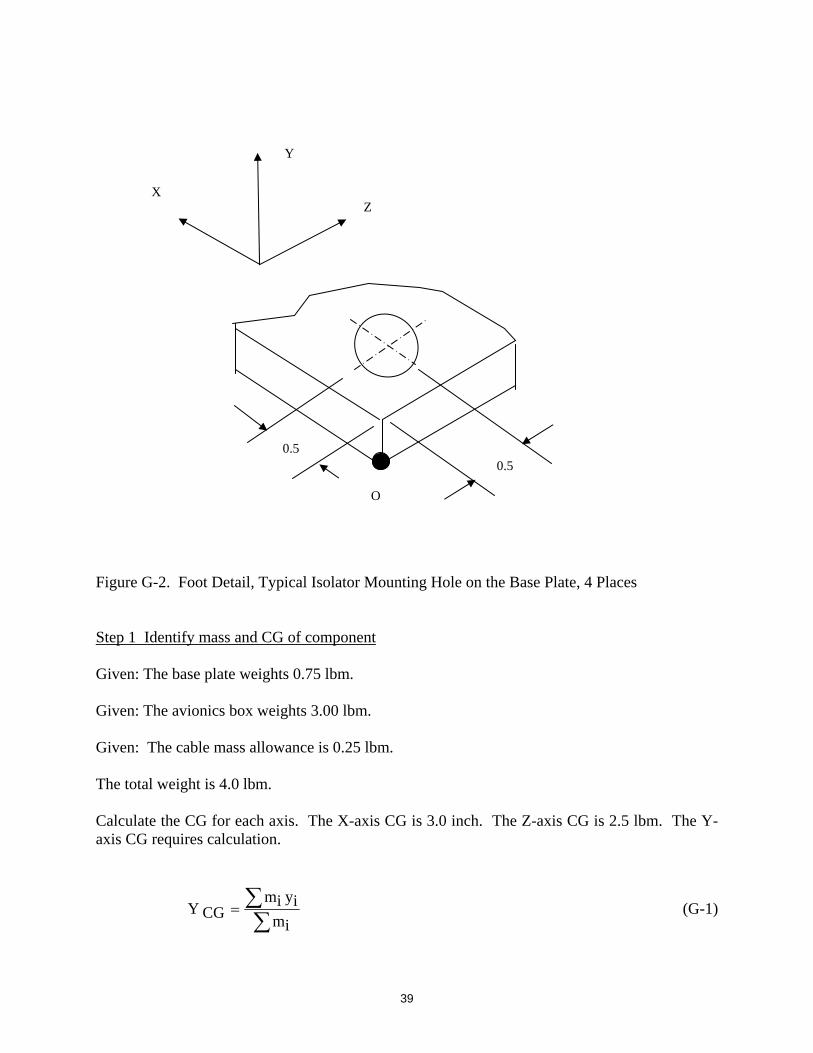
39
Figure G-2. Foot Detail, Typical Isolator Mounting Hole on the Base Plate, 4 Places Step 1 Identify mass and CG of component Given: The base plate weights 0.75 lbm. Given: The avionics box weights 3.00 lbm. Given: The cable mass allowance is 0.25 lbm. The total weight is 4.0 lbm. Calculate the CG for each axis. The X-axis CG is 3.0 inch. The Z-axis CG is 2.5 lbm. The Y-axis CG requires calculation.
imiyim
CGY (G-1)
0.5
Y
X Z
O
0.5
40
lbm4
in75.0lbm25.3in125.0lbm75.0CGY
= 0.633 inch (G-2)
As an alternative, this calculation could be performed using a CAD program. Step 2 Identify any cable or tubing mass This was already done in Step 1. Step 3 Identify moments of inertia This step could be performed using hand calculations, but the bookkeeping is rather involved since the parallel axis theorem must be used. As an alternative, a CAD program or software utility may be used. Nevertheless, here are the calculations for the sample problem. The avionics box is assumed to have uniform mass density. Calculate the polar moments of inertia for the base plate about its own CG. Use equations (11) through (14). The inertia about the Y-axis can be neglected.
2inlbm225.02512
75.0CGown plate, Jx
(G-3)
2inlbm566.1CGown plate, Jx (G-4)
2inlbm225.026
12
75.0CGown plate, Jz
(G-5)
2inlbm254.2CGown plate, Jz (G-6)
Calculate the polar moments of inertia for the base plate about the system CG.
in508.0in)125.0633.0(plated (G-7)
41
2inlbm194.02in508.0lbm75.02platedm (G-8)
2inlbm194.02inlbm566.1CG system plate, Jx (G-9)
2inlbm760.1CG system plate, Jx (G-10)
2inlbm194.02inlbm254.2CG system plate, Jz (G-11)
2inlbm448.2CG system plate, Jz (G-12)
Calculate the polar moments of inertia for the avionics box about its own CG.
2inlbm212512
25.3CGown box, Jx
(G-13)
2inlbm042.7CGown box, Jx (G-14)
2inlbm212412
25.3CGown box, Jz
(G-15)
2inlbm604.4CGown box, Jz (G-16)
Calculate the polar moments of inertia for the avionics box about the system CG.
in117.0in)633.075.0(boxd (G-17)
2inlbm044.02in117.0lbm25.32boxdm (G-18)

42
2inlbm044.02inlbm042.7CG system box, Jx (G-19)
2inlbm086.7CG system box, Jx (G-20)
2inlbm044.02inlbm604.4CG system box, Jz (G-21)
2inlbm648.4CG system box, Jz (G-22)
The total inertia about the system CG is
2inlbm)086.7760.1(Jx (G-23)
2inlbm85.8Jx (G-24)
2inlbm)648.4447.2(Jz (G-25)
2inlbm10.7Jz (G-26)
Step 4. Identify maximum expected temperate range
Given: The temperature range is between 20°F and 100°F Step 5. Identify rigid-body acceleration loads Given: The maximum expected rigid-body acceleration is 10 G axial and 2 G lateral. Step 6. Calculate the quasi-static load against isolators The axial load is 4 lbm x 10 G = 40 lbf.

43
The lateral load is 4 lbm x 2 G = 8 lbf. Step 7. Identify natural frequency of component in hardmounted configuration, particularly any circuit board natural frequencies Given: The avionics box has a circuit board with a natural frequency of 200 Hz. Step 8. Identify whether isolators will interfere with the component’s operation, such as the case with an INS system. Given: The avionics box is not an INS system. It does not have any moving parts. The isolators will not interfere with is operation. Step 9. Identify any need for electrical grounding Given: The avionics box must maintain an electrical ground with the bulkhead. The isolators are non-conductive. They will break metal-to-metal contact. The box will be designed with a grounding terminal that will be connected with a wire to the bulkhead. Step 10. Identify any need for thermal grounding Given: The avionics component produce only a small amount of heat. Thermal grounding is unnecessary. Step 11. Identify any need for alignment Given: The component does not have any precise alignment requirements. The cables connected to the box have sufficient slack. Step 12. Identify available volume and clearance in launch vehicle for isolated component Given: The maximum relative displacement of the avionics component must be no greater than + 0.375 inch. This is the limit to guarantee that the isolated component does not impact adjacent structures.

44
Step 13. Identify shock MPE level Given: The shock MPE is shown in Figure G-3
1
10
100
1000
10000
10 100 1000 10000
NATURAL FREQUENCY (Hz)
PE
AK
AC
CE
L (G
)
SRS Q=10 SAMPLE SHOCK SPECIFICATION
Figure G-3.
45
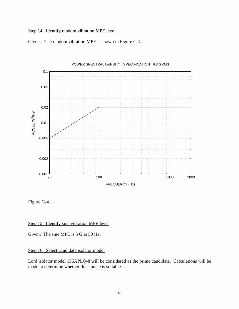
Step 14. Identify random vibration MPE level Given: The random vibration MPE is shown in Figure G-4
0.001
0.002
0.005
0.01
0.02
0.05
0.1
100 100020 2000
FREQUENCY (Hz)
AC
CE
L (G
2 /Hz)
POWER SPECTRAL DENSITY SPECIFICATION 6.3 GRMS
Figure G-4. Step 15. Identify sine vibration MPE level Given: The sine MPE is 5 G at 50 Hz. Step 16. Select candidate isolator model Lord isolator model 156APLQ-8 will be considered as the prime candidate. Calculations will be made to determine whether this choice is suitable.

46
Step 17. Verify isolator can withstand temperature range The given temperature range is between 20°F and 100°F. The temperature range per the specification for the Lord isolator is between 15°F and 100°F. Thus, the isolator can withstand the given temperature range. Step 18. Determine whether a base plate is necessary to accommodate isolators or to provide ballast mass. If so, compute mass, CG, and inertia values for complete system The design already includes a base plate as shown in Figure G-1. The mass properties of the base plate have already been accounted for. Step 19. Calculate natural frequencies of isolated component with respect to translation and rotation The CG has a vertical offset above the plane where the isolators attach to the base plate. The model thus has coupled rotation and translation. Nevertheless, the simplified approach is used here. Each isolator has a dynamic stiffness of 80 lbf/in per the specification given in the main text. Furthermore, the stiffness is isoelastic. There are four isolators. The total stiffness is thus 320 lbf/in in each axis. The translational natural frequency is
m
k
2
1fn
(G-27)
lbm4sec^2/in lbf
lbm386in/lbf320
2
1fn
(G-28)
Hz28fn (G-29) Assume that there is translational motion simultaneously in each axis at this frequency.

47
The rotational frequency about the X-axis is approximately
Jx
k
2
Lxxrotationfn
(G-30)
Note that equation (G-30) is a special case of equation (E-19). The distance from each isolator to the CG along the X-axis is
Lx = ( 3.0 – 0.5 ) in = 2.5 in (G-31)
2inlbm85.8
sec^2/in lbf
lbm386)in/lbf320(
2
in5.2xrotationfn
(G-32)
Hz47xrotationfn (G-33)
The rotational frequency about the Z-axis is approximately
Jz
k
2
Lzzrotationfn
(G-34)
The distance from each isolator to the CG along the Z-axis is
Lx = ( 2.5 – 0.5 ) in = 2.0 in (G-35)
2inlbm10.7
sec^2/in lbf
lbm386)in/lbf320(
2
in0.2zrotationfn
(G-36)

48
Hz42zrotationfn (G-37)
The natural frequencies are thus 28, 42, and 47 Hz. Step 20. Verify that isolated natural frequencies are at least one octave apart from component’s hardmounted natural frequency The highest natural frequency is 47 Hz. The circuit board natural frequency is given as 200 Hz, which is more than twice 47 Hz. Thus the requirement is verified. Step 21. Verify that isolators can withstand quasi-static load The displacement for the quasi-static load is
k
Fz (G-38)
The isolator model has a static stiffness of 56 lbf/in. The resulting axial isolator deflection is
)in/lbf56(4
G10lbm4z (G-39)
inch179.0z (axial) (G-40a)
Similarly, the lateral deflection for the 2 G load is
inch036.0z (lateral) (G-40b) The allowable deflection is 0.25 inch lateral and 0.38 inch axial, per the Lord isolator specifications. Thus, the requirement is verified. Step 22. Determine shock response in terms of acceleration and relative displacement The dominant mode is the translational mode, which has a natural frequency of 28 Hz. The peak acceleration response is 14 G at 28 Hz per Figure G-3.

49
2fn
A78.9Z (G-41)
The relative displacement for isolated component in the example is
2)Hz28(
G1478.9Z (G-42)
inch175.0Z (G-43) Step 23. Determine random vibration response in terms of acceleration and relative displacement The peak response acceleration is
)nf(PSDAYQnf76.3peakA (G-44)
Assume Q=10 for conservatism, even though a more realistic value is 5.
PSDAY = 0.0066 G^2/Hz at 28 Hz per Figure G-4.
) G^2/Hz 0.0066()10()Hz28(76.3peakA (G-45)
peakA 5.1 G (G-46)
The peak relative displacement is
2)Hz28(
G1.578.9Z (G-47)
inch064.0Z (G-48)
50
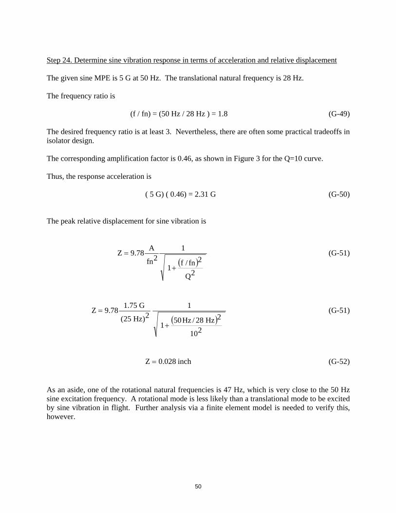
Step 24. Determine sine vibration response in terms of acceleration and relative displacement The given sine MPE is 5 G at 50 Hz. The translational natural frequency is 28 Hz. The frequency ratio is
(f / fn) = (50 Hz / 28 Hz ) = 1.8 (G-49) The desired frequency ratio is at least 3. Nevertheless, there are often some practical tradeoffs in isolator design. The corresponding amplification factor is 0.46, as shown in Figure 3 for the Q=10 curve. Thus, the response acceleration is
( 5 G) ( 0.46) = 2.31 G (G-50) The peak relative displacement for sine vibration is
2Q
2fn/f1
12fn
A78.9Z
(G-51)
210
2Hz28/Hz501
12)Hz25(
G75.178.9Z
(G-51)
inch028.0Z (G-52)
As an aside, one of the rotational natural frequencies is 47 Hz, which is very close to the 50 Hz sine excitation frequency. A rotational mode is less likely than a translational mode to be excited by sine vibration in flight. Further analysis via a finite element model is needed to verify this, however.
51
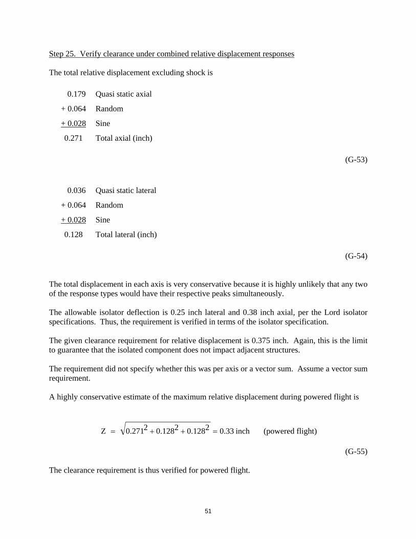
Step 25. Verify clearance under combined relative displacement responses The total relative displacement excluding shock is
0.179 Quasi static axial
+ 0.064 Random
+ 0.028 Sine
0.271 Total axial (inch)
(G-53)
0.036 Quasi static lateral
+ 0.064 Random
+ 0.028 Sine
0.128 Total lateral (inch)
(G-54)
The total displacement in each axis is very conservative because it is highly unlikely that any two of the response types would have their respective peaks simultaneously. The allowable isolator deflection is 0.25 inch lateral and 0.38 inch axial, per the Lord isolator specifications. Thus, the requirement is verified in terms of the isolator specification. The given clearance requirement for relative displacement is 0.375 inch. Again, this is the limit to guarantee that the isolated component does not impact adjacent structures. The requirement did not specify whether this was per axis or a vector sum. Assume a vector sum requirement. A highly conservative estimate of the maximum relative displacement during powered flight is
inch33.02128.02128.02271.0Z (powered flight)
(G-55)
The clearance requirement is thus verified for powered flight.

52
Shock is considered separately because it is assumed to occur during a coast period, when there are no other sources of dynamic excitation. Again, the peak shock displacement is 0.175 inch in a given axis. The vector sum is
inch30.02175.02175.02175.0Z (shock) (G-56)
Again, the vector sum is highly conservative. The resulting displacement is 0.075 inches less than the clearance limit. Example Conclusion The isolated avionics design using the Lord isolators thus appears to reasonably meet the requirements. A finite element analysis could be used to verify this conclusion. The finite element analysis could account for coupling. It could also address the response of the rotational modes with respect to each shock and vibration environment.

53
APPENDIX H
Retrofitting Design for Isolation The following is taken from Reference 6. It should only be considered as a “band-aid” solution for retrofitting isolators to an existing design where the space it too limited for a grommet or bushing-type isolator.
The mount configuration consists of two silicone rubber washers and a length of plastic shrink tubing. The washers isolate the equipment package mounting flange from the vehicle structure. The shrink tubing placed around the mounting bolt completes the isolation of the equipment from the vehicle structure. The washers are semi rigid, and are in the 50 to 60 durometer range. The installation is completed by use of a gage to control the compression of the washers from an initial 0.125 inch to a 0.090 inch thickness. This configuration, in addition to providing good shock isolation, usually satisfies requirements relative to structural vibrations, space limitations, weight, equipment alignment, and universal application.