Autonomous Sensing and Control of Wing Stall Using a …tcorke/w.J_Aircraft_Papers/JA-2007-Smart...
12
Autonomous Sensing and Control of Wing Stall Using a Smart Plasma Slat Mehul P. Patel ∗ and Zak H. Sowle † Orbital Research, Inc., Cleveland, Ohio 44103-3733 and Thomas C. Corke ‡ and Chuan He § University of Notre Dame, Notre Dame, Indiana 46556 DOI: 10.2514/1.24057 The concept of a self-governing smart plasma slat for active sense and control of flow separation and incipient wing stall is presented. The smart plasma slat design involves the use of an aerodynamic plasma actuator on the leading edge of a two-dimensional NACA 0015 airfoil in a manner that mimics the effect of a movable leading-edge slat of a conventional high-lift system. The self-governing system uses a single high-bandwidth pressure sensor and a feedback controller to operate the actuator in an autonomous mode with a primary function to sense and control incipient flow separation at the wing leading edge and to delay incipient stall. Two feedback control techniques are investigated. Wind tunnel experiments demonstrate that the aerodynamic effects of a smart actuator are consistent with the previously tested open-loop actuator, in that stall hysteresis is eliminated, stall angle is delayed by 7 deg, and a significant improvement in the lift-to-drag ratio is achieved over a wide range of angles of attack. These feedback control approaches provide a means to further reduce power requirements for an unsteady plasma actuator for practical air vehicle applications. The smart plasma slat concept is well suited for the design of low-drag, quiet, high- lift systems for fixed-wing aircraft and rotorcraft. Nomenclature C L = coefficient of lift C L;max = maximum coefficient of lift c = airfoil chord length F = nondimensional frequency of actuator f = modulation frequency of actuator L=D = ratio of lift to drag L sep = extent of flow separation R e = Reynolds number R echord = Reynolds number based on length c Sr = Strouhal number t = airfoil maximum thickness U 1 = freestream velocity x = distance measured from the leading edge = angle of attack, deg stall = stall angle, deg Introduction H IGH-LIFT systems play an important role in the design of air vehicles. The wings on most modern-day air vehicles are equipped with high-lift systems, generally in the form of leading- edge slats and trailing-edge flaps. These devices have been shown to enhance the aerodynamic performance of air vehicles through increasing the maximum coefficient of lift, lift-to-drag ratio, and stall angle. Advantages of such performance-enhancing devices include improvements in maneuverability, turn rates, glide range and payload, and reductions in takeoff/landing distance and field length requirements. Although the benefits of high-lift devices are well documented in the open literature, it is also known that the use of movable control surfaces increases airframe noise and vibration, especially at high deflection angles. At these conditions, most of the noise originates from the separated flow in the gap regions which contribute to the form drag component of the viscous drag of the wing. At off-design conditions, in particular, the drag penalty from these devices is very high. By present estimates used in the wing and tail design, eliminating the hinge gaps would result in a 10% drag decrease [1]. Another drawback of movable control surfaces is that a deploy and retract mechanism is required, which adds volume, weight, and cost to the high-lift system. To enhance the aerodynamic and structural performance of the air vehicle, it is therefore desired to either fully replace the traditional movable control surfaces with hingeless devices that retain/improve the aerodynamic effects, or limit their deflection angles, without compromising lift performance. Owing to the rapid growth in instrumentation, materials, and control technologies, the roles and capabilities of flow control and aerostructures are evolving. The use of smart aerostructures that can react rapidly to changing flow conditions to improve the aerodynamic and structural efficiencies of aircraft is gaining momentum. It is envisioned that future air vehicle designs will involve surfaces that shelter an integrated system of sensors, flow- control actuators, and feedback controllers that are able to adapt to unpredictable conditions (structural damage, wind shear, stall/spin, etc.) and reconfigure themselves in flight to regain/enhance control. This is the theme of the present work—the design of a smart aerostructure (slat) that can be used as an intelligent high-lift device with no moving parts. This work presents the concept and experimental evaluation of a smart plasma slat: a low-drag, hingeless, high-lift device which uses a sensor, an aerodynamic plasma actuator, and a feedback controller for autonomous sense and control of leading-edge flow separation and wing stall. This paper reports follow on work towards the application of a (single-dielectric-barrier discharge) plasma actuator as a performance-enhancing device for a high-lift system. Previously, the effects of an “open-loop” plasma slat and plasma Received 20 March 2006; revision received 1 August 2006; accepted for publication 1 August 2006. Copyright © 2006 by M. P. Patel and T. C. Corke. Published by the American Institute of Aeronautics and Astronautics, Inc., with permission. Copies of this paper may be made for personal or internal use, on condition that the copier pay the $10.00 per-copy fee to the Copyright Clearance Center, Inc., 222 Rosewood Drive, Danvers, MA 01923; include the code 0021-8669/07 $10.00 in correspondence with the CCC. ∗ Director, Aerodynamics Group, 4415 Euclid Avenue, Suite 500. Senior Member AIAA. † Aerospace Engineer, 4415 Euclid Avenue, Suite 500. ‡ Clark Chair Professor, Aerospace and Mechanical Engineering Department, 101 Hessert Laboratory for Aerospace Research. Associate Fellow AIAA. § Ph.D. Candidate, Aerospace and Mechanical Engineering Department, 101 Hessert Laboratory for Aerospace Research. JOURNAL OF AIRCRAFT Vol. 44, No. 2, March–April 2007 516
-
Upload
nguyenkhue -
Category
Documents
-
view
215 -
download
0
Transcript of Autonomous Sensing and Control of Wing Stall Using a …tcorke/w.J_Aircraft_Papers/JA-2007-Smart...

Autonomous Sensing and Control of Wing StallUsing a Smart Plasma Slat
Mehul P. Patel∗ and Zak H. Sowle†
Orbital Research, Inc., Cleveland, Ohio 44103-3733
and
Thomas C. Corke‡ and Chuan He§
University of Notre Dame, Notre Dame, Indiana 46556
DOI: 10.2514/1.24057
The concept of a self-governing smart plasma slat for active sense and control offlow separation and incipientwing
stall is presented. The smart plasma slat design involves the use of an aerodynamic plasma actuator on the leading
edge of a two-dimensional NACA 0015 airfoil in a manner that mimics the effect of a movable leading-edge slat of a
conventional high-lift system. The self-governing system uses a single high-bandwidth pressure sensor and a
feedback controller to operate the actuator in an autonomous mode with a primary function to sense and control
incipient flow separation at the wing leading edge and to delay incipient stall. Two feedback control techniques are
investigated. Wind tunnel experiments demonstrate that the aerodynamic effects of a smart actuator are consistent
with the previously tested open-loop actuator, in that stall hysteresis is eliminated, stall angle is delayed by 7 deg, and
a significant improvement in the lift-to-drag ratio is achieved over a wide range of angles of attack. These feedback
control approaches provide a means to further reduce power requirements for an unsteady plasma actuator for
practical air vehicle applications. The smart plasma slat concept is well suited for the design of low-drag, quiet, high-
lift systems for fixed-wing aircraft and rotorcraft.
Nomenclature
CL = coefficient of liftCL;max = maximum coefficient of liftc = airfoil chord lengthF� = nondimensional frequency of actuatorf = modulation frequency of actuatorL=D = ratio of lift to dragLsep = extent of flow separationRe = Reynolds numberRe�chord� = Reynolds number based on length cSr = Strouhal numbert = airfoil maximum thicknessU1 = freestream velocityx = distance measured from the leading edge� = angle of attack, deg�stall = stall angle, deg
Introduction
H IGH-LIFT systems play an important role in the design of airvehicles. The wings on most modern-day air vehicles are
equipped with high-lift systems, generally in the form of leading-edge slats and trailing-edge flaps. These devices have been shown toenhance the aerodynamic performance of air vehicles throughincreasing themaximum coefficient of lift, lift-to-drag ratio, and stallangle. Advantages of such performance-enhancing devices include
improvements in maneuverability, turn rates, glide range andpayload, and reductions in takeoff/landing distance and field lengthrequirements.Although the benefits of high-lift devices are well documented in
the open literature, it is also known that the use of movable controlsurfaces increases airframe noise and vibration, especially at highdeflection angles. At these conditions, most of the noise originatesfrom the separated flow in the gap regions which contribute to theform drag component of the viscous drag of the wing. At off-designconditions, in particular, the drag penalty from these devices is veryhigh. By present estimates used in the wing and tail design,eliminating the hinge gaps would result in a 10% drag decrease [1].Another drawback of movable control surfaces is that a deploy andretract mechanism is required, which adds volume, weight, and costto the high-lift system. To enhance the aerodynamic and structuralperformance of the air vehicle, it is therefore desired to either fully
replace the traditional movable control surfaces with hingelessdevices that retain/improve the aerodynamic effects, or limit theirdeflection angles, without compromising lift performance.Owing to the rapid growth in instrumentation, materials, and
control technologies, the roles and capabilities of flow control andaerostructures are evolving. The use of smart aerostructures that canreact rapidly to changing flow conditions to improve theaerodynamic and structural efficiencies of aircraft is gainingmomentum. It is envisioned that future air vehicle designs willinvolve surfaces that shelter an integrated system of sensors, flow-control actuators, and feedback controllers that are able to adapt tounpredictable conditions (structural damage, wind shear, stall/spin,etc.) and reconfigure themselves in flight to regain/enhance control.This is the theme of the present work—the design of a smartaerostructure (slat) that can be used as an intelligent high-lift devicewith no moving parts.This work presents the concept and experimental evaluation of a
smart plasma slat: a low-drag, hingeless, high-lift device which usesa sensor, an aerodynamic plasma actuator, and a feedback controllerfor autonomous sense and control of leading-edge flow separationand wing stall. This paper reports follow on work towards theapplication of a (single-dielectric-barrier discharge) plasma actuatoras a performance-enhancing device for a high-lift system.Previously, the effects of an “open-loop” plasma slat and plasma
Received 20 March 2006; revision received 1 August 2006; accepted forpublication 1August 2006. Copyright © 2006 byM. P. Patel and T. C. Corke.Published by the American Institute of Aeronautics and Astronautics, Inc.,with permission. Copies of this paper may be made for personal or internaluse, on condition that the copier pay the $10.00 per-copy fee to the CopyrightClearance Center, Inc., 222 Rosewood Drive, Danvers, MA 01923; includethe code 0021-8669/07 $10.00 in correspondence with the CCC.
∗Director, Aerodynamics Group, 4415 Euclid Avenue, Suite 500. SeniorMember AIAA.
†Aerospace Engineer, 4415 Euclid Avenue, Suite 500.‡Clark Chair Professor, Aerospace and Mechanical Engineering
Department, 101 Hessert Laboratory for Aerospace Research. AssociateFellow AIAA.
§Ph.D. Candidate, Aerospace and Mechanical Engineering Department,101 Hessert Laboratory for Aerospace Research.
JOURNAL OF AIRCRAFTVol. 44, No. 2, March–April 2007
516
flap (plasma actuators applied on the wing leading edge and trailingedge, respectively) on the aerodynamic performance of aNACA 0015 were discussed [2]. The present work is focused onformulating self-governing methods to enable “closed-loop”operation of a plasma slat. Much of this work is focused on reducingthe power levels of the plasma actuator for practical air vehicleapplications, hence due consideration was given to the design offeedback control approaches that enable a continuous self-governingplasma actuator using a simple commercial off-the-shelf (COTS)pressure sensor. Wind tunnel experiments were conducted on aslowly pitching 2-D NACA 0015 airfoil to validate two differentfeedback control techniques designed for autonomous control. Thedesigns are generic enough to be applied to any flow-controlapplication where smart sensing and control of incipient flowseparation is desired. The following sections provide a briefdiscussion of the different types of wing stall, plasma actuators,feedback control, and results from wind tunnel experiments.
Wing Stall and Control
Wing Stall
The stall of a wing is a very complex problem and still remains oneof the most important phenomena in aerodynamics. It occurs whenthe wing is unable to generate sufficient lift to keep the air vehicle inthe air which can happen if the vehicle speed is too slow and/or if theangle of attack is too sharp, causing the flow to separate at the leadingedge. Flow separation occurs when the boundary layer lifts off orseparates from the surface of the wing under the influence of viscousforces and adverse pressure gradients acting within the boundarylayer or due to geometrical aberrations [3,4]. Such low velocity andhigh � conditions are usually encountered during takeoff andlanding. Because of the large energy losses associated withboundary-layer separation, the performance of lifting surfaces isoften deteriorated; hence the use of effective high-lift systems iscrucial during such conditions.One way of delaying wing stall is by using a high-lift device such
as a leading-edge slat. It consists of a moving surface on the lowerside of the wing that extends out ahead of the wing leading edge. Itsprimary effect is to increase �stall andCL;max by allowing air from thehigh-pressure lower surface to circulate over the upper surface,which energizes the boundary layer and prevents flow separation,and therefore stall. Other examples of mechanical high-lift devicesinclude a droop nose, Krueger flap, slottedKruegerflap, and a slottedslat. These hinged high-lift devices are effective, to varying degrees,in extending the�stall andCL;max of the airfoil, however, they also addparasitic drag, weight, cost, and mechanical complexity to the high-lift system.Flow control offers alternative methods of separation control
using low-power hingeless devices. Some of the previouslydemonstrated flow-control methods for controlling flow separationinclude periodic excitation [5,6], passive and active vortexgenerators [7,8], and pulsed jet actuators [9]. In thiswork, a relativelynew type of flow-control device, an aerodynamic plasma actuator[10], is used for controlling leading-edge flow separation and wingstall using feedback control. Because the present work deals withformulation based on the detection of flow characteristics (bubbleformation, adverse pressure gradient, etc.) associated with separatedflows, it seems relevant to first touch on the subject of wing stall.
Types of Stall
Decades of research in understanding the different stallingcharacteristics and their relation to the state of the boundary layer hasled to a generalization of three types of stall that are widely acceptedtoday for low-speed flows, albeit their demarcation calls for a morecareful examination. These include 1) the thin-airfoil stall, wherethere is a gradual loss of lift at low lift coefficients as the turbulentreattachment point moves rearward; 2) the leading-edge stall, wherethere is an abrupt loss of lift, as the angle of attack formaximum lift isexceeded, with little to no rounding over the lift curves; and 3) thetrailing-edge stall, where there is a gradual loss of lift at highCL as the
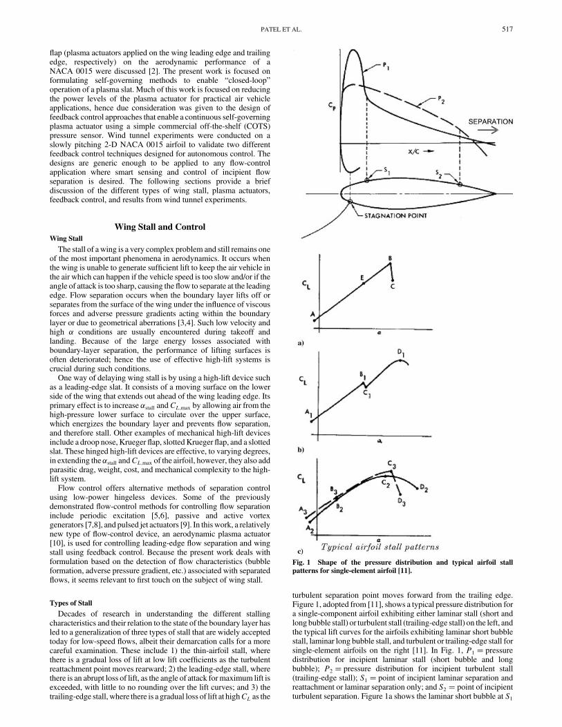
turbulent separation point moves forward from the trailing edge.Figure 1, adopted from [11], shows a typical pressure distribution fora single-component airfoil exhibiting either laminar stall (short andlong bubble stall) or turbulent stall (trailing-edge stall) on the left, andthe typical lift curves for the airfoils exhibiting laminar short bubblestall, laminar long bubble stall, and turbulent or trailing-edge stall forsingle-element airfoils on the right [11]. In Fig. 1, P1 � pressuredistribution for incipient laminar stall (short bubble and longbubble); P2 � pressure distribution for incipient turbulent stall(trailing-edge stall); S1 � point of incipient laminar separation andreattachment or laminar separation only; and S2 � point of incipientturbulent separation. Figure 1a shows the laminar short bubble at S1
Fig. 1 Shape of the pressure distribution and typical airfoil stall
patterns for single-element airfoil [11].
PATEL ET AL. 517

bursts andCL drops abruptly from B toC; Fig. 1b shows the laminarlong bubble at S1 develops into an extended region of separation forCLs between C1 and D1, where flow is unstable; and Fig. 1c showsthe turbulent trailing edge stall. A2B2C2D2 boundary layer changesfrom laminar to transition to turbulent and then separates at C2.A3B3C3D3 boundary layer progresses from laminar to localseparation, then to turbulent reattachment, and finally to turbulentseparation.Laminar stall is caused as a result of a very high suction peak and
succeeding high adverse pressure gradient near the leading edge,whereas turbulent stall occurs as a result of a relatively high adversepressure gradient near the aft part of airfoil. Theflows associatedwiththin-airfoil stall and leading-edge stall are characterized by theaccompanying separation bubble. When the laminar boundary layerseparates from the surface of the airfoil, the resulting separated shearlayer may curve back onto the airfoil surface within a short distance.The region of circulatory motion underneath a separated flowbetween points of separation and reattachment is defined as a “shortbubble.” In certain cases, however, the separated viscous layer,which is formed in the neighborhood of the location of minimumpeak pressure on the airfoil, may not reattach to the surface at all ormay reattach after 0.2–0.3 chord lengths downstream. In either case,the flow over the airfoil is unsteady because of the presence of thelarge region of circulatorymotion underneath the separatedflow.Theextended separated region is defined as a “long separation bubble.”The presence of the short laminar separation bubble near the leadingedge of the airfoil may give rise to laminar stall. This type of stall isdistinguished from the turbulent or trailing-edge stall by the fact thatin the case of trailing-edge stall, turbulent boundary-layer separationtakes place near the aft end of the airfoil causing the existence of asizable region of separated flow.A laminar separation bubble is either called short or long
depending on themagnitude ofRe (based on velocity andmomentumthickness of boundary-layer separation) and pressure gradient. If thebubble is short and the angle of attack is then increased, theseparation point moves forward to a region of increasing surfacecurvature. Eventually turbulent reattachment of the full shear layerfails to take place, and there is a consequent sudden loss of lift andincrease in drag. Separation involving formation of a short bubblecan occur on most conventional airfoil sections of moderatethickness to chord ratio in the range of 0:09< t=c < 0:15.If the bubble is long, then an increase in the angle of attack
produces a progressive rearwardmovement of the reattachment, thusincreasing the length of the bubble until it coincides with the trailingedge. Stall is reached at about this angle of attack; any furtherincrease in � results in a gradual reduction in lift. This separationprocess can also occur on most conventional thin airfoils having t=cratios up to about 0.09, and it is usually called thin-airfoil stall.Aerodynamically, whereas the formation and development of a longbubble has a considerable adverse effect on drag via the pressuredistribution, the existence of a short bubble has a negligible effect upto the harmful stall condition.The turbulent separation from the trailing edge is characteristic of
most conventional thick airfoil sections in a range of t=c greater than0.12. An increase in angle of attack produces a gradual forwardmovement of the point of separation and steady and gradual decreasein lift. It is possible for both short bubble and trailing-edge separationto exist on the same families of airfoils at the same time over a certainrange ofRe. The former generally starts to develop at a lower angle ofattack than does the latter. This combination of separationconsequently displays characteristics of both short bubble and thetrailing-edge separation, with the possibility of either a semiroundedlift curve peak followed by an abrupt decrease in lift or a relativesharp lift curve peak followed by a relatively rapid decrease in lift.In all cases, the flow over the wing is unsteady because of the
presence of the large region of circulatory motion underneath theseparated flow. The ultimate goal of the present work is to developmethods to identify incipient flow separation by correlating pressurefluctuations with physical phenomena (bubble formation, windgusts, etc.) which can be used as a feedback rule for switching theplasma actuator on or off for autonomous control. In this work, we
investigate a slowly pitching two-dimensional NACA 0015 airfoiland capture the pressure fluctuations near the wing leading edgeusing a high-bandwidth pressure sensor located just downstream ofthe leading-edge plasma actuator (at x=c� 0:05) to detect incipientflow separation. Two feedback control methods are developed:1) amplitude peak sense and control (APSC), and 2) pressureamplitude sense and control (PASC). The former relies on thedetection of actuator frequency peaks in the flowfield under theinfluence of an upstreamunsteady actuator, and the latter relies on thedetection of high amplitude peaks over ranges of key preselectedfrequencies that exhibit strong characteristics of incipient flowseparation. Wind tunnel experiments are conducted to validate bothmethods of feedback control.
Aerodynamic Plasma Actuator
An aerodynamic plasma actuator is a particular configuration ofthe dielectric-barrier discharge (a surface discharge) which consistsof two electrodes that are separated by a dielectric material. One ofthe electrodes is typically exposed to the surrounding air and theother is fully encapsulated by a dielectricmaterial, as shown in Fig. 2.When an a.c. voltage (5 kHz) is supplied to the electrodes, atsufficiently high amplitude levels (3–12 kV peak to peak), the airionizes in the region of the largest electric field potential. Thistypically occurs at the edge of the electrode that is exposed to the airand spreads out over the area projected by the covered electrode,directing momentum into the surrounding air.The process of ionizing the air in this configuration is classically
known as a single-dielectric-barrier discharge [12]. The basis of thisplasma actuator configuration is that the ionized air (plasma) in thepresence of an electric field gradient produces a body force on theambient air [13], which induces a virtual aerodynamic shape over thesurface around the actuator. The body-force vector can be tailored fora given application by configuring the orientation and design of theelectrode geometry. The body-force representation is also aconvenient form to incorporate the effect of the actuators in Navier–Stokes (NS) simulations, which are currently being used to designand predict the performance of plasma actuators for variousapplications [14–16].An excellent review of the physics and the underlying
mechanisms of the aerodynamic plasma actuator is provided byEnloe et al. [12,13]. The use of single-dielectric-barrier-dischargeplasma actuators for flow-control applications has been demon-strated by several researchers. Examples of flow-control applicationsusing plasma actuators include exciting 3-D boundary-layerinstabilities on a sharp cone at Mach 3.5 [17], lift augmentation onwings [18], separation control for low-pressure turbine blades [19],leading-edge separation control on wing sections [20], phasedplasma arrays for unsteady flow control [21], and control of thedynamic stall vortex on oscillating airfoils [22]. More recently, theuse of plasma actuators has been demonstrated for air vehicleapplications such as plasma flaps and slats [2] and plasma wing forhingeless flight control [23]. A newmethod to enhance the effects ofa low-power “unsteady”plasma actuator are investigated using novelplasma-optimized airfoil design concepts [24].The majority of the applications for plasma actuators referenced
above deals with the control of flows in an open-loop mode. Theauthors were unable to find any work in the literature on the
Exposed electrode
Dielectric
a.c voltage
Coveredelectrode
Substrate
Induced flowExposed electrode
Dielectric
Coveredelectrode
Substrate
Induced flow
Fig. 2 Asymmetric electrode arrangement of an aerodynamic plasma
actuator.
518 PATEL ET AL.

experimental use of plasma actuators using feedback control beforethis work. To this end, this paper presents the first look into the use ofsmart plasma actuators for autonomous sense and control ofseparated flows. The two main outcomes of the present work are 1) asmart skin that can operate continuously in an autonomous mode tomaintain the aerodynamic efficiency at optimum settings, and2) reduction of power requirements for the plasma actuators byturning them off when they are either not necessary or would beineffective.In the present work, the plasma actuators used were made from
two 0.0254 mm thick copper electrodes separated by two 0.1 mm (4-mil) thick Kapton film layers. The Kapton has a breakdown voltageof approximately 7 kV per 10�3 in: thickness and a dielectricconstant of 3.3, which provide good electrical properties. Theelectrodes were arranged in the asymmetric arrangement illustratedin Fig. 2. They were overlapped by a small amount (approximately1 mm) to ensure a uniform plasma in the spanwise direction. Theplasma actuator was bonded directly to the surface of the model. Atthe leading edge, where the flow is sensitive to the nose radius, a0.1 mm recess wasmolded into themodel to secure the actuator flushto the surface. The electrodes were positioned so that the junctionbetween the exposed and covered electrodes was precisely at theleading edge. The actuator induced an accelerating velocitycomponent in the mean freestream direction over the suction surfaceof the model.The leading-edge plasma actuator, located at x=c� 0:0, was
operated in an unsteady manner. The a.c. carrier frequency suppliedto the electrodes was 5 kHz and the a.c. voltage supplied to theelectrodes was on the order of 3–12 kVp-p. The power used by theactuator was approximately 2–4Wper linear foot of actuator span. Inthe unsteady mode, very short duty cycles are possible, whichreduces the actuator power requirements significantly. For example,a 10% duty cycle provided results better than the “steady” operationwhich used 100%duty cycle. The unsteady actuator frequency fwasdetermined based on a Strouhal number scaling of a dimensionlessfrequency, F� � fLsep=U1 � 1. For all cases presented here, theunsteady modulation frequency of the actuator was 166 Hz and theactuator was operated at 10% duty cycle.
Experimental Setup
The airfoil used for this study was a 2-D NACA 0015 (hereafter0015) with a 12.7 cm (5-in.) chord and a 25.4 cm (10-in.) span.Photographs of the 0015 are shown in Fig. 3. The 0015 was chosenfor study because its characteristics are well documented in theliterature and the airfoil was also the subject of an experiment ondynamic stall control using plasma actuators, which provided flowvisualization records (see Fig. 4) [22]. The size of the airfoil was acompromise between minimizing blockage effects, especially athigh � and maintaining a large enough chord Reynolds number,Re�chord�. At the largest angle of attack tested, that is, �� 23 deg, theblockage was 8.5%, which still ultimately required correction in themeasured lift and drag coefficients. The airfoil was cast using anepoxy-based polymer in a two-piece mold. The mold was preciselymachined using a numerical-controlled milling machine.Experiments were conducted at Re�chord� � 1:8 � 105 (U1�
21 m=s) in a subsonic wind tunnel located in the Center for FlowPhysics and Control (FlowPAC) in the Hessert Laboratory at theUniversity of Notre Dame. The facility is an open-return draw-downwind tunnel with a 0:421 m � 0:421 m � 1:8 m (long) test section.The tunnel consists of a removable inlet with a series of 12 screensfollowed by a 24:1 contraction that attaches to the test section. Thetest section is equipped with a clear Plexiglas sidewall that allowsoptical access to view themodel. The backwall of the test section hasremovable panels to allow access into the test section.The 0015 used in the study was mounted vertically to the support
sting of a lift-drag force balance on top of the test section. The airfoilwas suspended between endplates that were attached parallel to theceiling and floor of the test section. The endplates were designed toproduce a two-dimensional flow around the airfoil. A hole in theceiling endplate accommodated the sting supporting the airfoil. A
hole in the floor endplate allowed access for the actuator wiring. Thishole was aligned with the support sting so that it would not interferewith angular positioning of the airfoil when setting different angles ofattack. A stepper motor on the force balance drove the angular
Electrode covered with Kapton Film
Exposed Electrode
Suction side
Electrode covered with Kapton Film
Exposed Electrode
Suction side
Fig. 3 Photographs of the 2-D NACA 0015 airfoil model.
α = 16 deg
α = 18 deg
α = 20 deg
α = 22 deg
α = 24 deg
Actuator OFF Actuator ON
α = 16 deg
α = 18 deg
α = 20 deg
α = 22 deg
α = 24 deg
Fig. 4 Flow visualization records of the 2-D 0015 airfoil model with the
steady leading-edge plasma actuator off and on [22].
PATEL ET AL. 519

position of the support sting. Its motion was controlled by the dataacquisition computer through software. With this, the angularposition was repeatable to�0:005 deg. Figure 5 shows the diagramof the experimental system.
Feedback Control
Two methods of predicting incipient flow separation at the wingleading edge were developed based on the frequency and timedomain analyses of the pressure data, which were thenexperimentally verified via closed-loop control experiments. TheAPSC method is based on the detection of frequency peaks in theflowfield under the influence of an upstream unsteady actuator, andthe other PASC method relies on the detection of high amplitudepeaks of key pressure frequencies that are strong precursors of flowseparation. In both the approaches, we track incipient separation onthe upper surface of the airfoil to predict stall. The plasma actuatorwas operated at an a.c. amplitude of 7 kV�p-p� and at a modulationfrequency of 166Hz (F� � 1). Pressure data were sampled at 1 kHz,and lift and drag was measured on the wing using a force balance.Pressure measurements were made using a high-bandwidth pressure
sensor located at the leading edge, x=c� 0:05, on the suction side.This location was chosen to allow detection of incipient flowseparation at the leading edge. Figure 6 shows the photograph andschematic of the airfoil model and the pressure sensor used in theexperiments. As shown in Fig. 6, a slot was machined into thepressure side of the airfoil which was used to accommodate thesensor. The slot cavity was sealed by clear tape.
Amplitude Peak Sense-and-Control (APSC) Method
The diagram in Fig. 5 represents a block diagram for the APSCcontrol method. To find the rule for feedback control, thecharacteristic of static pressure at x=c� 0:05 was investigated ateach angle of attack when the plasma was off and on. Figure 7 showsthe fast Fourier transform (FFT) analysis of discrete sampled staticpressure data at different angles of attack. For� 12 deg there is nodifference between the spectra with the plasma actuator off and on.However, when � reaches 13 deg, which is 1 deg lower than the flowseparates at the leading edge, a dominant frequency and its harmonicappears in the spectrum when the plasma actuator is on. Thisfrequency corresponds to the unsteady forcing frequency of theplasma actuator which was 166 Hz in this case.At �� 14:5 deg, which is immediately after �stall, a low-
frequency dominates the flow when the actuator is off. This lowfrequency was investigated by Broeren and Bragg [25]. The resultsshowed that the development and growth of the leading-edge
Fig. 5 Diagram of the smart plasma slat experimental system.
x/ c = 5%
Pressure SensorStatic Pressure Port
NACA 0015
a)
b)
c)
x/ c = 5%
Pressure SensorStatic Pressure Port
NACA 0015
Fig. 6 a) Photograph of 2-D NACA 0015 airfoil model with a fast-response pressure sensor; b) close view of the pressure sensor;
c) schematic of NACA 0015 airfoil with a pressure sensor and location of
the pressure port.
Fig. 7 Power spectrum of discrete sampled static pressure at�� 8, 13,
14.5, and 22 deg when plasma actuator is turned off and on.
520 PATEL ET AL.

separation bubble that merges with the trailing-edge turbulentboundary-layer separation plays a key role in the low-frequencyoscillation. When the plasma actuator is turned on, this lowfrequency vanishes and the spectral peak at 166 Hz again appears. Asimilar peak in the measured pressure spectrum is observed all theway up to �� 23 deg, which was the highest angle of attackinvestigated.At a low angle of attack (� < 13 deg), just before the leading-edge
stall, a small separation region (bubble) begins to form downstreamof the sensing port at x=c� 0:05. This would be point S1 in Fig. 1. Itis speculated that this location (S1) is just past the maximumthickness point of the 0015 (x=c� 0:3), as illustrated in Fig. 8. Theplasma actuator design and frequency operation were meant to forcespanwise vortices that efficiently mix outer high-momentum fluidwith the low-momentum fluid near the surface, causing the flow toreattach. At lower angles of attack, the flow at the leading edge isattached. When the plasma actuator is on, the strong favorablepressure gradient around the leading-edge nose damps the unsteadyinput from the actuator so that even close to the leading edge, justdownstream of the actuator (x=c� 0:05), the pressure fluctuationsdue to the actuator are not sensed.As � increases, the small separation bubble gradually moves
forward until in the case of the present experiment, at�� 13 deg,S1moves forward of the pressure sensor location. The small separationbubble is very receptive to the unsteady condition produced by theplasma actuator. As a result, the pressure sensor now shows a spectralpeak at the actuator unsteady frequency. Note that this smallseparation bubble is a precursor of the full leading-edge separation
on this airfoil at lowReynolds number. Therefore, having it appear inthe spectrum at prestall angles of attack provides a feedback signal tokeep the actuator on.The evidence of a separation bubble that occurs near the leading
edge comes from two bits of information. The first is the observationthat when the unsteady pressure was measured at the 10% c location,a larger� (1.5–2 deg) precursor of stallwas observed compared to the1 deg � precursor obtained with the unsteady pressure measurementmeasured at the 5% location. This indicates that the separationbubble was moving forward as the � increased. The secondindication of our interpretation was the prediction of a separationpoint between 5–10% c at a 13 deg � obtained using the X-Foilprogram.A more remarkable feature of this method of separation detection
is that even after the flow has been reattached by the unsteady plasmaactuator, the pressure sensor near the leading edge still senses a peakin the spectrum at the unsteady frequency as long as the flowwill notattach naturally. However, even with the actuator on, if � is lowenough for the flow at the leading edge to be naturally attached, thespectral peak at the actuator frequency is not visible. Thus, this
Fig. 8 a) Schematic of separation bubble position at � < 13 deg;b) schematic of interaction between separation bubble and vortex
generated by the plasma actuator.
start
change angle of attack
actuator on
actuator on
acquire data
FFT analysis
spike at f
actuator off
Yes
No
Fig. 9 Flowchart for the amplitude peak sense-and-control (APSC)feedback control method.
Fig. 10 Lift coefficient versus angle of attack and drag polar for the NACA 0015 airfoil at 21 m=s with APSC feedback control.
PATEL ET AL. 521
characteristic provides a method to both sense incipient separation toturn the actuator on, and sense when the actuator no longer needs tobe on, saving actuator power.Based on this explanation of theAPSC, a control procedure shown
in Fig. 9 is implemented. First, at any given � of the airfoil, theunsteady plasma actuator is turned on, the pressure sensor time seriesis sampled, and the frequency spectrum is computed. If a spectralpeak is found at the actuator unsteady forcing frequency, the flow issensed to be close to separation, or at a large � at which if the actuatorwere turned off, the flow would separate. Thus, the unsteady plasmaactuator stays on. If the peak at the unsteady actuator frequency doesnot appear in the pressure spectra, the airfoil � is low enough for theflow to be far from separating. In this case, the plasma actuator isturned off. This control loop is exercised every time � is changed inthe laboratory experiment. In a flight scenario, it would be operatingautonomously in the control loop to always sense and controlincipient separation.A demonstration of the control procedure is presented in Fig. 10.
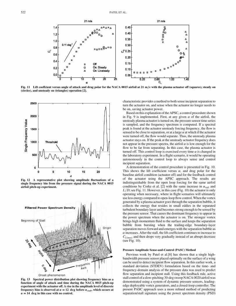
This shows the lift coefficient versus �, and drag polar for thebaseline airfoil condition (actuator off) and for the feedback controlof the actuator using the APSC approach. The results areindistinguishable from the open loop forcing for the same airfoilconditions by Corke et al. [2] with the same increase in �stall andL=D; see Fig. 11. However, in this case (Fig. 10) the actuator is onlyoperating when necessary, where in flight scenarios will ultimatelyuse less energy compared to open-loopflowcontrol.When the vortexgenerated by a plasma actuator goes through the separation bubble, itcollects the energy that resides in small eddies in the separatedturbulent boundary layer and becomes strong enough to be sensed bythe pressure sensor. That causes the dominant frequency to appear inthe power spectrum when the actuator is on. The stronger vortexbrings high momentum fluid to the surface and keeps the separationbubble from bursting when the trailing-edge boundary-layerseparationmoves forward and emerges with the separation bubble as� increases. After the stall, the lift coefficient continues to increase toCL�max� and then drops very gradually instead of an abrupt decrease(see Fig. 10).
Pressure Amplitude Sense-and-Control (PASC) Method
Previous work by Patel et al.[8] has shown that a single high-bandwidth pressure sensor placed optimally on the surface of a wingcan be used to detect incipient flow separation. In this earlier work, astandard deviation (STDEV) formulation based on the time- andfrequency-domain analysis of the pressure data was used to predictflow separation and incipient stall. Using this feedback rule, activestall control of a slow-pitching 30-deg sweepNACA0020 airfoil wasdemonstrated using a system of dynamic pressure sensors, leading-edge deployable vortex generators, and a closed-loop controller. Thepresent PASC approach uses a more refined method of predictingseparation/stall signature using the power spectrum density (PSD)
Fig. 11 Lift coeffcient versus angle of attack and drag polar for the NACA 0015 airfoil at 21 m=s with the plasma actuator off (squares), steady on
(circles), and unsteady on (triangles) operation [2].
0 5 10 15 20
0
500
1000
1500
2000
2500
Threshold
a
Sin
gle
Fre
quen
cy V
alue
0 5 10 15 20
0
500
1000
1500
2000
2500
Threshold
0 5 10 15 20
0
500
1000
1500
2000
2500
Threshold
a
Sin
gle
Fre
quen
cy V
alue
Fig. 12 A representative plot showing amplitude fluctuations of asingle frequency bin from the pressure signal during the NACA 0015
airfoil pitch-up experiment.
Fig. 13 Spectral power distribution plot showing frequency bins as a
function of angle of attack and time during the NACA 0015 pitch-upexperiment with the actuator off. A rise in the amplitude level of discrete
frequency bins is observed at �� 12 deg before �stall, which occurs at
�� 14 deg in this case with no control.
522 PATEL ET AL.
analysis of discrete frequency bins of the pressure signal for feedbackcontrol, as opposed to looking at an aggregate of all frequencies, aswas done in the STDEV technique [8].The PASC method allows us to examine how the power
(amplitude) of the pressure time series is distributed with frequency.A characteristic rise in the amplitude levels of pressure frequencies ismeasured before �stall, which is used as a precursor to the onset ofstall phenomena. An increase in the amplitude (power) of thepressure signal is indicative of increased flow turbulence in thevicinity of the pressure sensor which is caused by high adversepressure gradient and a separating flowfield. Identifying theseprecursors of flow separation at the wing leading edge enables thecontrol system to activate the plasma actuator to control the flowseparation and delay of �stall.To demonstrate the performance of the smart plasma slat using the
PASC approach, experiments were conducted on a slowly pitching0015 (�0:118 deg =s) using a single pressure sensor at x=c� 0:05on the suction side. The experimental setup was exactly the same for
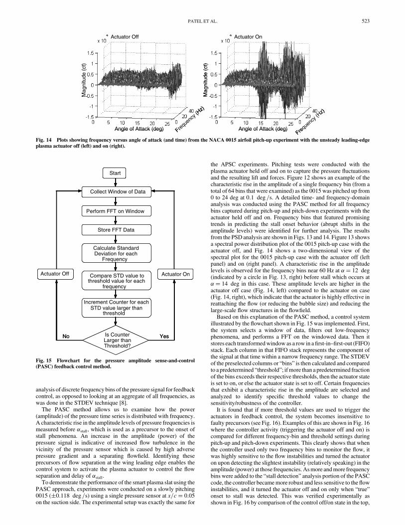
the APSC experiments. Pitching tests were conducted with theplasma actuator held off and on to capture the pressure fluctuationsand the resulting lift and forces. Figure 12 shows an example of thecharacteristic rise in the amplitude of a single frequency bin (from atotal of 64 bins that were examined) as the 0015 was pitched up from0 to 24 deg at 0:1 deg =s. A detailed time- and frequency-domainanalysis was conducted using the PASC method for all frequencybins captured during pitch-up and pitch-down experiments with theactuator held off and on. Frequency bins that featured promisingtrends in predicting the stall onset behavior (abrupt shifts in theamplitude levels) were identified for further analysis. The resultsfrom the PSD analysis are shown in Figs. 13 and 14. Figure 13 showsa spectral power distribution plot of the 0015 pitch-up case with theactuator off, and Fig. 14 shows a two-dimensional view of thespectral plot for the 0015 pitch-up case with the actuator off (leftpanel) and on (right panel). A characteristic rise in the amplitudelevels is observed for the frequency bins near 60 Hz at �� 12 deg(indicated by a circle in Fig. 13, right) before stall which occurs at�� 14 deg in this case. These amplitude levels are higher in theactuator off case (Fig. 14, left) compared to the actuator on case(Fig. 14, right), which indicate that the actuator is highly effective inreattaching the flow (or reducing the bubble size) and reducing thelarge-scale flow structures in the flowfield.Based on this explanation of the PASC method, a control system
illustrated by the flowchart shown in Fig. 15 was implemented. First,the system selects a window of data, filters out low-frequencyphenomena, and performs a FFT on the windowed data. Then itstores each transformedwindow as a row in afirst-in–first-out (FIFO)stack. Each column in that FIFO stack represents the component ofthe signal at that time within a narrow frequency range. The STDEVof the preselected columns or “bins” is then calculated and comparedto a predetermined “threshold”; ifmore than a predetermined fractionof the bins exceeds their respective thresholds, then the actuator stateis set to on, or else the actuator state is set to off. Certain frequenciesthat exhibit a characteristic rise in the amplitude are selected andanalyzed to identify specific threshold values to change thesensitivity/robustness of the controller.It is found that if more threshold values are used to trigger the
actuators in feedback control, the system becomes insensitive tofaulty precursors (see Fig. 16). Examples of this are shown in Fig. 16where the controller activity (triggering the actuator off and on) iscompared for different frequency-bin and threshold settings duringpitch-up and pitch-down experiments. This clearly shows that whenthe controller used only two frequency bins to monitor the flow, itwas highly sensitive to the flow instabilities and turned the actuatoron upon detecting the slightest instability (relatively speaking) in theamplitude (power) at those frequencies. Asmore andmore frequencybins were added to the “stall detection” analysis portion of the PASCcode, the controller becamemore robust and less sensitive to theflowinstabilities, and it turned the actuator off and on only when “true”onset to stall was detected. This was verified experimentally asshown in Fig. 16 by comparison of the control off/on state in the top,
Angle of Attack (deg)Frequ
ency (
Hz)
Mag
nitu
de (
ct)
Mag
nitu
de (
ct)
Angle of Attack (deg)Fre
quen
cy (H
z)
Actuator Off Actuator On
Angle of Attack (deg)Frequ
ency (
Hz)
Mag
nitu
de (
ct)
Mag
nitu
de (
ct)
Angle of Attack (deg)Fre
quen
cy (H
z)
Actuator Off Actuator On
Fig. 14 Plots showing frequency versus angle of attack (and time) from the NACA 0015 airfoil pitch-up experiment with the unsteady leading-edge
plasma actuator off (left) and on (right).
Actuator On
Start
Collect Window of Data
Perform FFT on Window
Store FFT Data
Calculate Standard Deviation for each
Frequency
Compare STD value to threshold value for each
frequency
STD value larger than threshold
Actuator Off
Is Counter Larger than Threshold?
YesNo
Actuator On
Start
Collect Window of Data
Perform FFT on Window
Store FFT Data
Calculate Standard Deviation for each
Frequency
Compare STD value to threshold value for each
frequency
Increment Counter for each STD value larger than
threshold
Actuator Off
Is Counter Larger than Threshold?
YesNo
Fig. 15 Flowchart for the pressure amplitude sense-and-control(PASC) feedback control method.
PATEL ET AL. 523
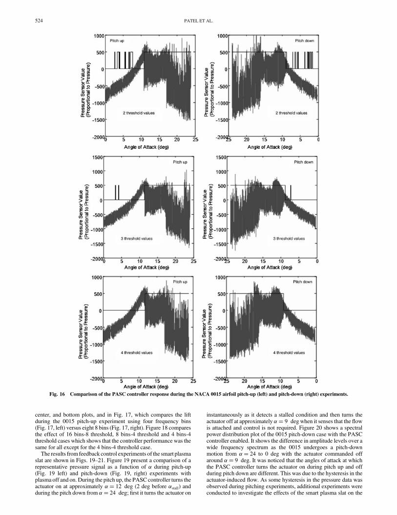
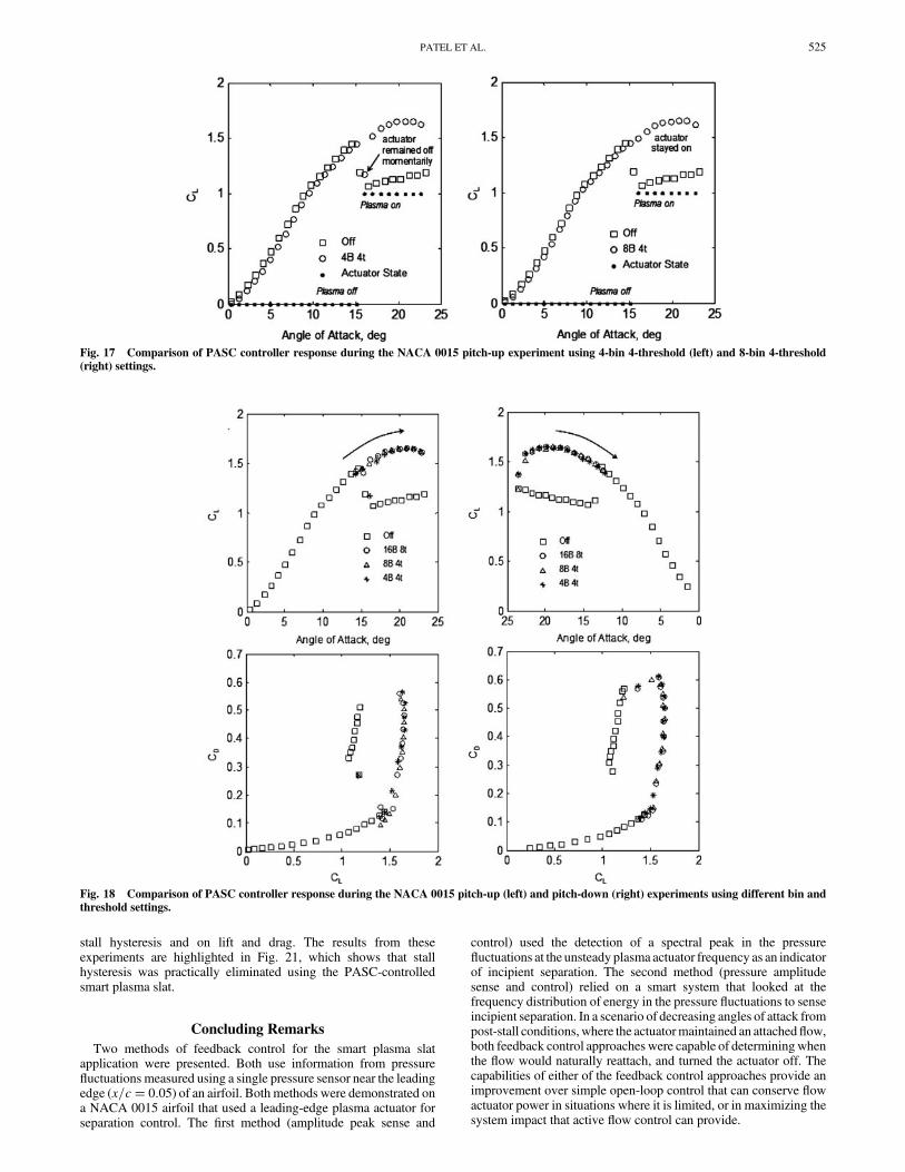
center, and bottom plots, and in Fig. 17, which compares the liftduring the 0015 pitch-up experiment using four frequency bins(Fig. 17, left) versus eight 8 bins (Fig. 17, right). Figure 18 comparesthe effect of 16 bins-8 threshold, 8 bins-4 threshold and 4 bins-4threshold cases which shows that the controller performance was thesame for all except for the 4 bins-4 threshold case.The results from feedback control experiments of the smart plasma
slat are shown in Figs. 19–21. Figure 19 present a comparison of arepresentative pressure signal as a function of � during pitch-up(Fig. 19 left) and pitch-down (Fig. 19, right) experiments withplasma off and on. During the pitch up, the PASC controller turns theactuator on at approximately �� 12 deg (2 deg before �stall) andduring the pitch down from �� 24 deg; first it turns the actuator on
instantaneously as it detects a stalled condition and then turns theactuator off at approximately �� 9 degwhen it senses that the flowis attached and control is not required. Figure 20 shows a spectralpower distribution plot of the 0015 pitch-down case with the PASCcontroller enabled. It shows the difference in amplitude levels over awide frequency spectrum as the 0015 undergoes a pitch-downmotion from �� 24 to 0 deg with the actuator commanded offaround �� 9 deg. It was noticed that the angles of attack at whichthe PASC controller turns the actuator on during pitch up and offduring pitch down are different. This was due to the hysteresis in theactuator-induced flow. As some hysteresis in the pressure data wasobserved during pitching experiments, additional experiments wereconducted to investigate the effects of the smart plasma slat on the
Fig. 16 Comparison of the PASC controller response during the NACA 0015 airfoil pitch-up (left) and pitch-down (right) experiments.
524 PATEL ET AL.
stall hysteresis and on lift and drag. The results from theseexperiments are highlighted in Fig. 21, which shows that stallhysteresis was practically eliminated using the PASC-controlledsmart plasma slat.
Concluding Remarks
Two methods of feedback control for the smart plasma slatapplication were presented. Both use information from pressurefluctuations measured using a single pressure sensor near the leadingedge (x=c� 0:05) of an airfoil. Both methods were demonstrated ona NACA 0015 airfoil that used a leading-edge plasma actuator forseparation control. The first method (amplitude peak sense and
control) used the detection of a spectral peak in the pressurefluctuations at the unsteady plasma actuator frequency as an indicatorof incipient separation. The second method (pressure amplitudesense and control) relied on a smart system that looked at thefrequency distribution of energy in the pressure fluctuations to senseincipient separation. In a scenario of decreasing angles of attack frompost-stall conditions,where the actuatormaintained an attachedflow,both feedback control approaches were capable of determiningwhenthe flow would naturally reattach, and turned the actuator off. Thecapabilities of either of the feedback control approaches provide animprovement over simple open-loop control that can conserve flowactuator power in situations where it is limited, or in maximizing thesystem impact that active flow control can provide.
Fig. 17 Comparison of PASC controller response during the NACA 0015 pitch-up experiment using 4-bin 4-threshold (left) and 8-bin 4-threshold
(right) settings.
Fig. 18 Comparison of PASC controller response during the NACA 0015 pitch-up (left) and pitch-down (right) experiments using different bin and
threshold settings.
PATEL ET AL. 525

Fig. 19 An overlay plot showing comparisons of a representative pressure signal from 0015 pitch-up (left) and pitch-down (right) experiments withplasma off, plasma on, and using a PASC-enabled feedback controller to drive the plasma actuator.
24
12
0
18
6
Time (sec)
Angle of Attack (deg)
Frequency (Hz)
Vol
tage
pro
port
iona
l to
Pre
ssur
e S
igna
l
Controller Command Off
Controller Command On
Controller Command Initial State Off
Pitch down from 24 to 0 deg
24
12
0
18
6
Time (sec)
Angle of Attack (deg)
Frequency (Hz)
Vol
tage
pro
port
iona
l to
Pre
ssur
e S
igna
l
Controller Command Off
Controller Command On
Controller Command Initial State Off
24
12
0
18
6
24
12
0
18
6
Time (sec)
Angle of Attack (deg)
Frequency (Hz)
Vol
tage
pro
port
iona
l to
Pre
ssur
e S
igna
l
Controller Command Off
Controller Command On
Controller Command Initial State Off
Pitch down from 24 to 0 deg
Fig. 20 Spectral power distribution plot from the 0015 pitch-down experiment using the PASC-enabled controller.
0
0.2
0.4
0.6
0.8
1
1.2
1.4
1.6
1.8
2
0 2 4 6 8 10 12 14 16 18 20 22 24
Plasma OffPlasma On
Stall hysteresisPlasma off
CL
Angle of attack (deg)
Pitch-up
Pitch-down
Pitch-down
Pitch-up
0
0.2
0.4
0.6
0.8
1
1.2
1.4
1.6
1.8
2
0 2 4 6 8 10 12 14 16 18 20 22 24
Plasma OffPlasma On
Stall hysteresisPlasma off
CL
Angle of attack (deg)
Pitch-up
Pitch-down
Pitch-down
Pitch-up
Fig. 21 Overlay of results from feedback control experiments showing near elimination of stall hysteresis on the 0015using thePASC smart plasma slat.
526 PATEL ET AL.
Acknowledgment
This workwas conducted under a SBIR Phase II Program from theUSAF/AFRL, VA, under Contract No. FA8650-04-C-3405monitored by the USAF Program Manager Charles F. Suchomel.
References
[1] Corke, T. C., Design of Aircraft, Prentice–Hall, New York, 2002.[2] Corke, T. C., He, C., and Patel, M. P., “Plasma Flaps and Slats: An
Application of Weakly-Ionized Plasma Actuators,”AIAA Paper 2004-2127, July 2004.
[3] Chang, P. K., Control of Separation, McGraw–Hill, New York, 1976.[4] Gad-el-Hak, M., and Bushnell, D. M., “Separation Control: Review,”
Journal of Fluid Engineering, Vol. 113, March 1991, pp. 5–30.[5] Greenblatt, D., and Wygnanski, I., “Control of Separation by Periodic
Excitation,” Progress in Aerospace Sciences, Vol. 37, No. 7, 2000,pp. 487–545.
[6] Seifert, A., Darabi, A., and Wygnanski, I., “Delay of Airfoil Stall byPeriodic Excitation,” Journal of Aircraft, Vol. 33,No. 4, 1996, pp. 691–698.
[7] Lin, J. C., Robinson, S. K., McGhee, R. J., and Valarezo, W. O.,“Separation Control on High-Lift Airfoils Via Micro-VortexGenerators,” Journal of Aircraft, Vol. 31, No. 6, 1994, pp. 1317–1323.
[8] Patel, M. P., Tilmann, C. P., and Ng, T. T., “Active Transparent StallControl System for Air Vehicles,” Journal of Aircraft, Vol. 40, No. 5,2003, pp. 993–997.
[9] McManus, K. R., Joshi, P. B., Legner, H. H., and Davis, S. J., “ActiveControl of Aerodynamic Stall Using Pulsed Jet Actuators,” AIAAPaper 1995-2187, June 1995.
[10] Corke, T. C., and Post, M., “Overview of Plasma Flow Control:Concepts, Optimization, and Applications,” AIAA Paper 2005-0563,Jan. 2005.
[11] Goradia, Suresh H., and Lyman, Victor, “Laminar Stall Prediction andEstimation of CL�max�,” Journal of Aircraft, Vol. 11, No. 9, 1974,pp. 528–536.
[12] Enloe, L., McLaughlin, T., VanDyken, R., Kachner, Jumper, E., andCorke, T. C., “Mechanisms and Response of a Single Dielectric BarrierPlasma Actuator: Plasma Morphology,” AIAA Journal, Vol. 42, No. 3,
March 2004, pp. 589–594.[13] Enloe, L.,McLaughlin, T., VanDyken, R., Kachner, Jumper, E., Corke,
T.C., Post,M., andHaddad,O., “Mechanisms andResponse of a SingleDielectric Barrier Plasma Actuator: Geometric Effects,” AIAA Journal,Vol. 42, No. 3, March 2004, pp. 595–604.
[14] Orlov,D.M., andCorke, T.C., “Numerical Simulation ofAerodynamicPlasma Actuator Effects,” AIAA Paper 2005-1083, Jan. 2005.
[15] Nelson, C.C., Cain,A. B., Patel,M. P., andCorke, T. C., “Simulation ofPlasma Actuators Using theWind-US Code,”AIAA Paper 2006-0634,Jan. 2006.
[16] Orlov, D.M., Corke, T. C., and Patel, M. P., “Electric CircuitModel forthe Aerodynamic Plasma Actuator,” AIAA Paper 2006-1206,Jan. 2006.
[17] Corke, T. C., Cavalieri, D., andMatlis, E., “Boundary Layer Instabilityon a Sharp Cone at Mach 3.5 with Controlled Input,” AIAA Journal,Vol. 40, No. 5, 2001, pp. 1015–1018.
[18] Corke, T. C., Jumper, E., Post, M., Orlov, D. and McLaughlin, T.,“Application of Weakly-Ionized Plasmas as Wing Flow-ControlDevices,” AIAA Paper 2002-0350, Jan. 2002.
[19] Huang, J., Corke, T. C., and Thomas, F., “Plasma Actuators forSeparation Control of Low-Pressure Turbine Blades,” AIAAPaper 2003-1027, AIAA Journal (to be pubished)..
[20] Post, M., and Corke, T. C., “Separation Control on High Angle ofAttack Airfoil Using Plasma Actuators,” AIAA Journal, Vol. 42,No. 11, 2004, pp. 2177–2184; also AIAA Paper 2003-1024.
[21] Corke, T. C., andMatlis, E., “Phased Plasma Arrays for Unsteady FlowControl,” AIAA Paper 2000-2323, Jan. 2000.
[22] Post,M., andCorke, T.C., “SeparationControlUsingPlasmaActuators—Stationary and Oscillating Airfoils,” AIAA Paper 2004-0841,2004.
[23] Corke, T. C., Mertz, B., and Patel, M. P., “Plasma Flow ControlOptimized Airfoil,” AIAA Paper 2006-1208, Jan. 2006.
[24] Patel,M. P., Ng, T. T., Vasudevan, S., Corke, T. C., andHe,C., “PlasmaActuators for Hingeless Aerodynamic Control of an Unmanned AirVehicle,” AIAA Paper 2006-3495, June 2006.
[25] Broeren, A. P., and Bragg, M. B., “Flowfield Measurements over anAirfoil During Natural Low-Frequency Oscillation near Stall,” AIAA
Journal, Vol. 37, No. 1, 1999, pp. 130–132.
PATEL ET AL. 527