Autonomous Robots Ref Design Using ROS on Sitara MPU and ...
30
1 TIDUEK9E – November 2018 – Revised April 2020 Submit Documentation Feedback Copyright © 2018–2020, Texas Instruments Incorporated Autonomous Robots Reference Design Using ROS on Sitara™ MPU and Antenna-On-Package mmWave Sensor Design Guide: TIDEP-01006 Autonomous Robots Reference Design Using ROS on Sitara™ MPU and Antenna-On-Package mmWave Sensor Description This reference design showcases autonomous robotics with the Processor SDK Linux running on the Sitara™ AM57x processor, and the mmWave SDK running on the IWR6843ISK, IWR6843AOPEVM, IWR1443BOOST, or IWR1843BOOST. This design demonstrates the functionality of an embedded robotic system where point-cloud data from the mmWave radar sensing is processed by the Sitara™ AM57x processor which runs Robot Operating System (ROS) and is the main processor for the overall system control. This design integrates enhanced processor SoCs, sensors, and builds embedded robotic systems upon widely adopted open source software components. In addition, it also supports the IWR6843 antenna-on-package variant of mmWave sensors which enables reduced design and manufacturing cost, simplified system design, smaller sensor footprint, and eventually faster time to market. This design provides a great entry point to evaluate full autonomous robotics with Sitara processing and mmWave sensing, and enables rapid development of robotics applications by leveraging TI’s hardware and software components. Resources TIDEP-01006 Design Folder AM5728 Product Folder AM57x Product Overview TMDSEVM572x Tool Folder IWR6843 Product Folder IWR6843ISK Tool Folder IWR6843AOPEVM Tool Folder Ask our TI E2E™ support experts Features • Embedded ROS on AM57x SoC • Seamless integration of the mmWave sensor including antenna-on-package with the AM57x and communicating using ROS – Integration with IWR6843, IWR1443, or IWR1843 EVM enables a 120º field of view (FOV) for obstacle detection across a wide azimuth coverage area – Integration with IWR6843AOPEVM enables a 130º FOV coverage in both azimuth and elevation to enable smarter decision making based on object height. • AM57x processor controls the mobile Kobuki platform to navigate and avoid obstacles sensed by mmWave sensors • Real-time visualization of navigation on a remote Ubuntu Linux box with ROS Rviz • Step-by-step guide to establish a fully-operational robotic system with sensory data and mobile base • Open source ROS implementation enables easy adjustment/enhancement of existing modules and addition of new modules Applications • Industrial: – Robotics (Industrial/Logistics/Delivery/Service Robots and Forklifts), object detection and localization, sorting, quality control and inspection, and packaging • Smart cities: – Security monitoring and road inspection • Drones: – Obstacle avoidance, path planning, and flight control
Transcript of Autonomous Robots Ref Design Using ROS on Sitara MPU and ...
1TIDUEK9E–November 2018–Revised April 2020Submit Documentation Feedback
Copyright © 2018–2020, Texas Instruments Incorporated
Autonomous Robots Reference Design Using ROS on Sitara™ MPU andAntenna-On-Package mmWave Sensor
Design Guide: TIDEP-01006Autonomous Robots Reference Design Using ROS onSitara™ MPU and Antenna-On-Package mmWave Sensor
DescriptionThis reference design showcases autonomousrobotics with the Processor SDK Linux running on theSitara™ AM57x processor, and the mmWave SDKrunning on the IWR6843ISK, IWR6843AOPEVM,IWR1443BOOST, or IWR1843BOOST. This designdemonstrates the functionality of an embedded roboticsystem where point-cloud data from the mmWaveradar sensing is processed by the Sitara™ AM57xprocessor which runs Robot Operating System (ROS)and is the main processor for the overall systemcontrol. This design integrates enhanced processorSoCs, sensors, and builds embedded robotic systemsupon widely adopted open source softwarecomponents. In addition, it also supports the IWR6843antenna-on-package variant of mmWave sensorswhich enables reduced design and manufacturingcost, simplified system design, smaller sensorfootprint, and eventually faster time to market. Thisdesign provides a great entry point to evaluate fullautonomous robotics with Sitara processing andmmWave sensing, and enables rapid development ofrobotics applications by leveraging TI’s hardware andsoftware components.
Resources
TIDEP-01006 Design FolderAM5728 Product FolderAM57x Product OverviewTMDSEVM572x Tool FolderIWR6843 Product FolderIWR6843ISK Tool FolderIWR6843AOPEVM Tool Folder
Ask our TI E2E™ support experts
Features• Embedded ROS on AM57x SoC• Seamless integration of the mmWave sensor
including antenna-on-package with the AM57x andcommunicating using ROS– Integration with IWR6843, IWR1443, or
IWR1843 EVM enables a 120º field of view(FOV) for obstacle detection across a wideazimuth coverage area
– Integration with IWR6843AOPEVM enables a130º FOV coverage in both azimuth andelevation to enable smarter decision makingbased on object height.
• AM57x processor controls the mobile Kobukiplatform to navigate and avoid obstacles sensed bymmWave sensors
• Real-time visualization of navigation on a remoteUbuntu Linux box with ROS Rviz
• Step-by-step guide to establish a fully-operationalrobotic system with sensory data and mobile base
• Open source ROS implementation enables easyadjustment/enhancement of existing modules andaddition of new modules
Applications• Industrial:
– Robotics (Industrial/Logistics/Delivery/ServiceRobots and Forklifts), object detection andlocalization, sorting, quality control andinspection, and packaging
• Smart cities:– Security monitoring and road inspection
• Drones:– Obstacle avoidance, path planning, and flight
control
Processor SDK Linux
A15 PRU-ICSS EVE C66x SGX Display
wilink8 usb-serial moduleftdi-sio
module
mmWave node Kobuki node serial
ROS launch script
ROS navigation stack
octomap fake_localization move_base
System Description www.ti.com
2 TIDUEK9E–November 2018–Revised April 2020Submit Documentation Feedback
Copyright © 2018–2020, Texas Instruments Incorporated
Autonomous Robots Reference Design Using ROS on Sitara™ MPU andAntenna-On-Package mmWave Sensor
An IMPORTANT NOTICE at the end of this TI reference design addresses authorized use, intellectual property matters and otherimportant disclaimers and information.
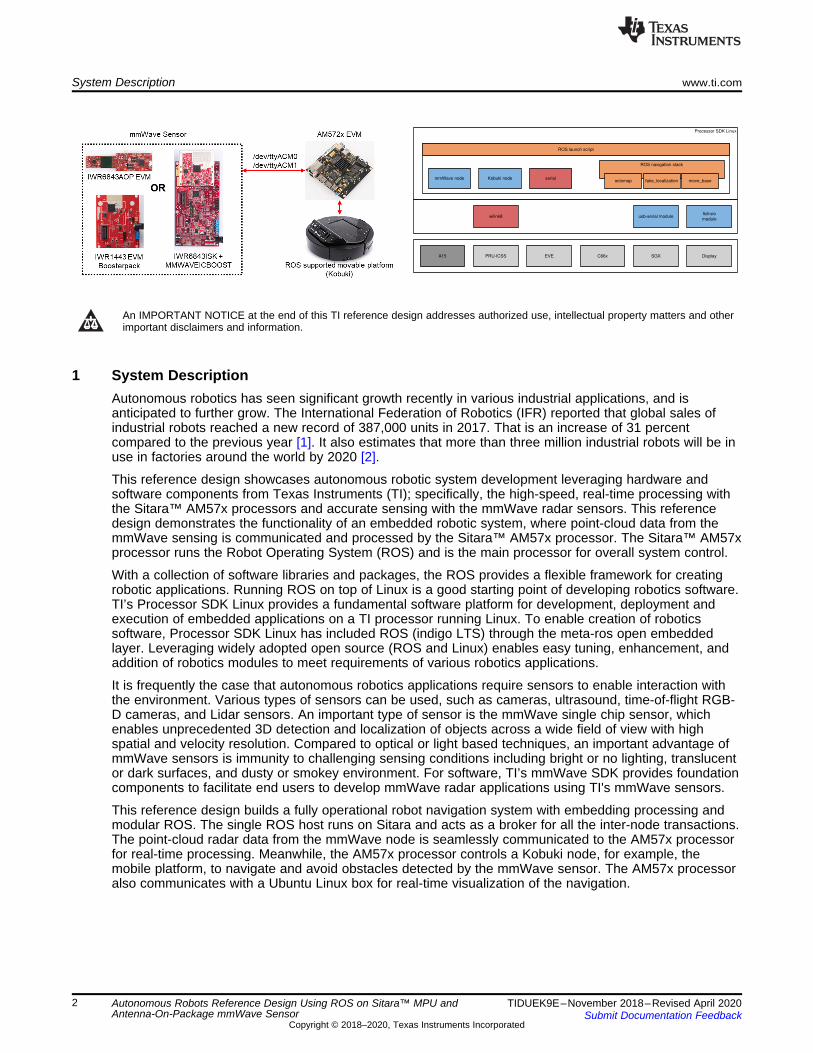
1 System DescriptionAutonomous robotics has seen significant growth recently in various industrial applications, and isanticipated to further grow. The International Federation of Robotics (IFR) reported that global sales ofindustrial robots reached a new record of 387,000 units in 2017. That is an increase of 31 percentcompared to the previous year [1]. It also estimates that more than three million industrial robots will be inuse in factories around the world by 2020 [2].
This reference design showcases autonomous robotic system development leveraging hardware andsoftware components from Texas Instruments (TI); specifically, the high-speed, real-time processing withthe Sitara™ AM57x processors and accurate sensing with the mmWave radar sensors. This referencedesign demonstrates the functionality of an embedded robotic system, where point-cloud data from themmWave sensing is communicated and processed by the Sitara™ AM57x processor. The Sitara™ AM57xprocessor runs the Robot Operating System (ROS) and is the main processor for overall system control.
With a collection of software libraries and packages, the ROS provides a flexible framework for creatingrobotic applications. Running ROS on top of Linux is a good starting point of developing robotics software.TI’s Processor SDK Linux provides a fundamental software platform for development, deployment andexecution of embedded applications on a TI processor running Linux. To enable creation of roboticssoftware, Processor SDK Linux has included ROS (indigo LTS) through the meta-ros open embeddedlayer. Leveraging widely adopted open source (ROS and Linux) enables easy tuning, enhancement, andaddition of robotics modules to meet requirements of various robotics applications.
It is frequently the case that autonomous robotics applications require sensors to enable interaction withthe environment. Various types of sensors can be used, such as cameras, ultrasound, time-of-flight RGB-D cameras, and Lidar sensors. An important type of sensor is the mmWave single chip sensor, whichenables unprecedented 3D detection and localization of objects across a wide field of view with highspatial and velocity resolution. Compared to optical or light based techniques, an important advantage ofmmWave sensors is immunity to challenging sensing conditions including bright or no lighting, translucentor dark surfaces, and dusty or smokey environment. For software, TI’s mmWave SDK provides foundationcomponents to facilitate end users to develop mmWave radar applications using TI's mmWave sensors.
This reference design builds a fully operational robot navigation system with embedding processing andmodular ROS. The single ROS host runs on Sitara and acts as a broker for all the inter-node transactions.The point-cloud radar data from the mmWave node is seamlessly communicated to the AM57x processorfor real-time processing. Meanwhile, the AM57x processor controls a Kobuki node, for example, themobile platform, to navigate and avoid obstacles detected by the mmWave sensor. The AM57x processoralso communicates with a Ubuntu Linux box for real-time visualization of the navigation.

www.ti.com System Description
3TIDUEK9E–November 2018–Revised April 2020Submit Documentation Feedback
Copyright © 2018–2020, Texas Instruments Incorporated
Autonomous Robots Reference Design Using ROS on Sitara™ MPU andAntenna-On-Package mmWave Sensor
1.1 Key System SpecificationsThe key system devices used in this reference design include the AM57x SoC and the IWR6843 mmWaveSensor. Other mmWave sensors, including the IWR1443, IWR1843, and IWR6843AOP EVMS, are alsosupported. Specifics related to enabling these other supported platforms are detailed in Section 3.2.2.1.2
1.1.1 AM57x SoCThe AM57x is a highly-integrated, pin-compatible, scalable, Sitara™ class processor. It has single- ordual-core Arm® Cortex®-A15 cores. The AM57x is designed for embedded applications includingProgrammable Logic Controllers (PLCs), industrial network switches, industrial gateways for protocoltranslation, human machine interface (HMI), grid infrastructure protection and communications, and otherindustrial use applications. The device includes the following subsystems:• Cortex®-A15 microprocessor unit (MPU) subsystem, including two Arm® Cortex®-A15 cores• Two digital signal processor (DSP) C66x subsystems• Two Embedded Vision Engine (EVE) susbsytems• Two Cortex-M4 subsystems, each including two Arm® Cortex®-M4 cores• Two dual-core Programmable Real-Time Units for Industrial Communications (PRU-ICSS)• Display subsystem (DSS)• Video Processing subsystem (VPE)• Video Input Capture (VIP)• 3D-graphics processing unit (GPU) subsystem, including POWERVR™ SGX544 dual-core• 2D-graphics accelerator (BB2D) subsystem, including Vivante™ GC320 core• Real-time clock (RTC) and Debug subsystems• The device provides a rich set of connectivity peripherals, including among others:
– USB 3.0 and 2.0– SATA 2– PCIe Gen2 Gigabit Ethernet Switch subsystems
• The device integrates on-chip memory, external memory interfaces and memory management.• The device includes support for functional safety system requirements:
– Error Detection and Correction:• Parity bit per byte on C66x DSP• L1 program cache and Single-Error Correction Dual-Error Detection (SECDED) on L2 memories• SECDED on Large L3 memory• SECDED on external DDR memory interface (EMIF1 only)
– MMU/MPU:• MMU used for key masters (Cortex-A15 MPU, Cortex-M4 IPU, C66x DSP, EDMA)• Memory protection of C66x cores• MMU inside the Dynamic Memory Manage
The AM57x can meet the requirement of high data input/output (I/O) bandwidth, for communicating withthe sensing component to retrieve the point cloud data. It also has the data processing power forprocessing the point cloud data in real time.

System Description www.ti.com
4 TIDUEK9E–November 2018–Revised April 2020Submit Documentation Feedback
Copyright © 2018–2020, Texas Instruments Incorporated
Autonomous Robots Reference Design Using ROS on Sitara™ MPU andAntenna-On-Package mmWave Sensor
1.1.2 mmWave SensorThe IWR6843 device is an integrated single-chip mmWave sensor based on FMCW radar technologycapable of operation in the 60- to 64-GHz band. The device is built with a Texas Instruments (TI) low-power 45-nm RFCMOS process to integrate analog RF as well as digital processing in a single chip.Furthermore, the IWR6843AOP variant features a short-range, wide field of view antenna-on-package(AOP), achieving unprecedented levels of integration in an extremely small form factor.
TI mmWave AOP sensors enable a wide variety of robotic applications, such as logistic robots, deliveryrobots, robotic arms etc. where autonomous robot makers must implement a high level of environmentalsensing and redundancy into robot systems to quickly detect and prevent possible collisions, using 3Dsensing capabilities to define safe and danger zones.
The AoP sensor design addresses three main challenges for robotics or factory automation:
• Wide 3D coverage with a single sensor: The AoP antenna’s wide FoV configuration provides a 130-degree view in the azimuth and elevation, which provides true 3D sensing enabling detection of theobject height and filtering out ground clutter. This maximizes a sensor’s accuracy and measurementperformance. The wide azimuth area coverage reduces the number of sensors used for area scanningand hence reduces overall system cost.
• Small form factor: The smaller form factor of AoP sensors means that they can fit into smallerenclosures, which is important for sleek, small autonomous robot designs such as autonomous guidedvehicles, delivery robots, and smaller robotic arms in factories for sense-and-avoid applications.
• Fast time to market: By eliminating expensive PCB substrates and RF expertise, AoP sensors simplifythe design and manufacturing process, enabling in-house designs and reducing time to market.
The IWR6843 is an ideal solution for low-power, self-monitored, and accurate radar systems in industrialapplications (such as, building automation, factory automation, drones, material handling, trafficmonitoring, and surveillance).
Key features of IWR6843:• FMCW transceiver:
– Integrated PLL, transmitter, receiver, baseband, and A2D– 60- to 64-GHz coverage with 4-GHz continuous bandwidth– Four receive channels– Three transmit channels– Option for integration of 4 receiver and 3 transmitter antenna-on-package (AOP)– Ultra-accurate chirp engine based on Fractional-N PLL– TX power: 10 dBm– RX noise figure: 14 dB– Phase noise at 1 MHz: -92 dBc/Hz
• Built-in calibration and self-test:– Arm® Cortex®-R4F-Based Radio Control System (RCS)– Built-in firmware (ROM)– Self-calibrating system across frequency and temperature
• On-Chip programmable core for embedded-user application:– Integrated Arm® Cortex®-R4F Microcontroller clocked at 200 MHz– On-Chip Bootloader supports Autonomous mode (Loading User application from QSPI Flash
memory)• Integrated peripherals:
– Internal Memories With ECC– ARM-R4F microcontroller for object detection, and interface control
• Supports autonomous mode (loading user application from QSPI flash memory)– Radar Hardware Accelerator (FFT, Filtering, and CFAR processing)– C674x DSP for advanced signal processing (IWR6843 or IWR6843 AOP only)

www.ti.com System Description
5TIDUEK9E–November 2018–Revised April 2020Submit Documentation Feedback
Copyright © 2018–2020, Texas Instruments Incorporated
Autonomous Robots Reference Design Using ROS on Sitara™ MPU andAntenna-On-Package mmWave Sensor
– I2C– Two SPI ports– CAN-FD interface– Up to six general-purpose ADC ports

System Overview www.ti.com
6 TIDUEK9E–November 2018–Revised April 2020Submit Documentation Feedback
Copyright © 2018–2020, Texas Instruments Incorporated
Autonomous Robots Reference Design Using ROS on Sitara™ MPU andAntenna-On-Package mmWave Sensor
2 System Overview
2.1 Block Diagram
Figure 1. TIDEP-01006 Block Diagram
As shown in Figure 1, this reference design consists of the following subsystems:• An AM57x running Processor SDK Linux and ROS. The AM57x processor acts as the ROS master,
runs the navigation stack, and interacts with the mmWave sensor (via the mmWave node) and themobile platform (via the Kobuki node) for autonomous navigation. The AM57x processor alsocommunicates with a Ubuntu Linux box which runs Rviz for visualizing the navigation.
• A mmWave radar sensor for object detection. Objects within the sensor's field of view are representedas 3D point clouds. Each point within the point cloud has an X, Y, and Z location coordinate as well asassociated doppler and SNR information. Depending on application requirements, any one of thefollowing mmWave evaluation modules can be used in the system:– IWR6843ISK and mmWaveICBOOST– IWR6843AOP EVM– IWR1443BOOST

www.ti.com System Overview
7TIDUEK9E–November 2018–Revised April 2020Submit Documentation Feedback
Copyright © 2018–2020, Texas Instruments Incorporated
Autonomous Robots Reference Design Using ROS on Sitara™ MPU andAntenna-On-Package mmWave Sensor
– IWR1843BOOST• Kobuki mobile platform• Ubuntu Linux box for remote control and real-time visualization with ROS Rviz (Ubuntu Linux box is
needed since Rviz requires an OpenGL desktop support, while Processor SDK Linux on the AM57xsupports OpenGL ES 2.0 only).

System Overview www.ti.com
8 TIDUEK9E–November 2018–Revised April 2020Submit Documentation Feedback
Copyright © 2018–2020, Texas Instruments Incorporated
Autonomous Robots Reference Design Using ROS on Sitara™ MPU andAntenna-On-Package mmWave Sensor
2.2 Design ConsiderationsTI's Processor SDK Linux provides a fundamental software platform for developing embedded applicationson a TI processor running Linux. To further enable the autonomous robotics, the Processor SDK Linuxhas included ROS, added and enhanced ROS packages to support navigation, and integrated themmWave ROS packages to leverage mmWave sensors for real-time sensing with high accuracy.
2.2.1 Embedded ROS with Processor SDK LinuxTo support the development of robotics applications, the Processor SDK Linux has included ROS (indigodistribution) through the meta-ros open embedded layer, starting from version 04.02.00.09. This isspecified in the processor-sdk oe-layersetup config file, which sets up the meta layers for the ProcessorSDK Linux:meta-ros,https://github.com/bmwcarit/meta-ros.git,master,e2566402ab108a19634354a934788109422cf409,layers=
meta-ros [3] provides a stable cross-compilation build system via the Yocto to establish the ROS indigodistribution in an embedded Linux system (for example, TI’s Processor SDK Linux system). It providesmany common ROS tools, libraries, and packages for developing and deploying robotics applications,including, but not limited to: catkin, control-msgs, hector-slam, kobuki, kobuki-core, kobuki-msgs, laser-geometry, navigation, octomap, roscpp-core, and so forth. The complete list can be found at the git repo.
The target filesystem of the AM57x has indigo ROS installed at /opt/ros/indigo, similar to the indigo ROSinstalled on a Ubuntu Linux box.root@am57xx-evm:/# ls -l /opt/ros/indigo/drwxr-xr-x 2 root root 4096 Oct 2 22:12 bindrwxr-xr-x 4 root root 4096 Sep 30 06:26 etcdrwxr-xr-x 141 root root 20480 Oct 2 22:12 lib-rw-r--r-- 1 root root 406 Sep 30 08:11 setup.bashdrwxr-xr-x 353 root root 16384 Oct 2 22:12 share
2.2.2 Add and Enhance ROS Packages to Support Navigation in Processor SDK LinuxTo support autonomous navigation with the Kobuki, several ROS modules are added or enhanced on topof the meta-ros layer in Processor SDK Linux. The corresponding Yocto recipes can be found fromrecipes-ros and listed here:├── hector-slam│ ├── hector-map-tools_0.3.5.bb│ ├── hector-nav-msgs_0.3.5.bb│ └── hector-trajectory-server_0.3.5.bb├── kobuki-driver│ ├── files│ │ └── kobuki.conf│ └── kobuki-driver_0.6.5.bbappend├── navigation│ ├── files│ │ ├── 0001-navigation-rotate-recovery-mmwave-changes.patch│ │ └── 0002-navigation-move-base-mmwave-changes.patch│ ├── move-base_1.12.14.bbappend│ └── rotate-recovery_1.12.14.bbappend├── octomap-server│ └── octomap-server_0.6.0.bb
Among these modules, the octomap-server and hector-slam modules are dependent ROS packages ofthe navigation but have not been included in the meta-ros. The kobuki-driver is adding the udev rule toinsert the kernel modules needed to detect the Kobuki connection. The move-base and rotate-recoverymodules under the navigation are enhanced to perform the initial rotation to clear the costmaps before thenavigation. The move-base module is also taking the fixes and enhancements from the lab forautonomous robotics with ROS for mmWave [5].

www.ti.com System Overview
9TIDUEK9E–November 2018–Revised April 2020Submit Documentation Feedback
Copyright © 2018–2020, Texas Instruments Incorporated
Autonomous Robots Reference Design Using ROS on Sitara™ MPU andAntenna-On-Package mmWave Sensor
2.2.3 Add ROS Packages to Enable mmWave in Processor SDK LinuxThe ROS framework is mainly based on the publisher-subscriber model, and in some cases the server-client mode. The ROS framework and libraries support the point cloud, which is also the data outputformat of the mmWave sensors. In the ROS environment, the consumer of the point cloud is decoupledfrom the point cloud producer since the data format is well defined.
Due to this modular nature of ROS, it is easy to replace one sensor with another as long as the dataformat (in this case point cloud) is the same. Therefore, ROS is a good fit for developing roboticsapplications with the mmWave sensors.
TI developed an mmWave ROS driver [4], and a lab for autonomous robotics with ROS for mmWave [5],with ROS running on a Ubuntu Linux box. In this reference design, the mmWave driver is added as a ROSpackage in Processor SDK Linux running on the AM57x. The ROS packages for autonomous robotics withmmWave are also added in Processor SDK Linux:turtlebot_mmwave_launchersti_mmwave_rospkgturtlebot_bringupturtlebot_descriptionturtlebot_navigation
Below lists the Yocto recipes for integrating the mmWave driver and the autonomous robotics formmWave in Processor SDK Linux:
├── mmwave-ros-autonomous-robotics_[version].bb├── mmwave-ros-pkg-master_[version].bb└── serial-ros_0.1.0.bb
Among the recipes above, the serial-ros is to build and install the serial driver for detecting the mmWaveEVM. The mmwave-ros-pkg-master is to build the mmWave driver ROS package for interfacing with themmWave EVM. In the lab for autonomous robotics with ROS for mmWave [5], turtlebot modules aremodified for achieving autonomous robotics with the mmWave sensor. In mmwave-ros-autonomous-robotics, these modified modules are reused with a few changes to set up the configuration and scripts toaccommodate Processor SDK Linux.
Update to the latest mmWave drivers: to use the latest mmWave SDK or other mmWave EVMs, seeSection 3.2.2.1.2
2.2.4 Recompile and Deploy ROS Packages With Processor SDK LinuxThe ROS indigo distribution and the ROS package required for navigation and mmWave sensing areincluded in the Processor SDK Linux. Autonomous navigation can run out of the box on the AM572x EVMas described in Test Results.
When it is needed to modify an existing or add a new ROS package, follow the procedure below torecompile and deploy the modified/new ROS package with Processor SDK Linux.
First, refer to Processor SDK Building The SDK to set up the build environment.
Then, create/modify the Yocto recipe for the ROS package, using the hector-trajectory-server_0.3.5.bband move-base_1.12.14.bbappend (described in Section 2.2) as the example for creating and modifying aROS package.
After the recipe is ready, follow Processor SDK Yocto Recipes to bitbake the recipe and install the newlybuilt ROS package. For example, run the command below to build move-base.MACHINE=am57xx-evm bitbake move-base
After the bitbake command above is successfully done, the newly built move-base .ipk files can be foundin ./build/arago-tmp-external-linaro-toolchain/work/armv7ahf-neon-linux-gnueabi/move-base/[version]/deploy-ipks directory. Copy these .ipk files to the target file system and run the commandbelow on the target to install the .ipk files:opkg install [package_ipk].ipk

System Overview www.ti.com
10 TIDUEK9E–November 2018–Revised April 2020Submit Documentation Feedback
Copyright © 2018–2020, Texas Instruments Incorporated
Autonomous Robots Reference Design Using ROS on Sitara™ MPU andAntenna-On-Package mmWave Sensor
2.3 Highlighted ProductsThis reference design leverages the AM572x EVM as the main processor and the ROS master. ThemmWave sensing is carried out with the IWR6843 Industrial Starter Kit (ISK) mounted on anMMWAVEICBOOST board. Both the AM572x EVM and the MMWAVEICBOOST board are assembled ona Kobuki mobile platform to form a fully operational robot navigation system.
2.3.1 AM572x EVMThe AM572x Evaluation Module (EVM) (see Figure 2) provides an affordable platform to quickly startevaluation of the Sitara™ Arm® Cortex®-A15 AM57x Processors (AM5728, AM5726, AM5718, AM5716)and accelerate development for HMI, machine vision, networking, medical imaging and many otherindustrial applications [6]. AM572x EVM is a development platform based on the dual Arm® Cortex®-A15,dual C66x DSP processor that is integrated with tons of connectivity (such as: PCIe, SATA, HDMI, USB3.0/2.0, dual Gigabit Ethernet, and more).
The AM572x EVM also integrates video and 3D/2D graphics acceleration, as well as a dual-coreProgrammable Real-time Unit (PRU) and dual Arm® Cortex™-M4 cores.
Figure 2. AM572x EVM
www.ti.com System Overview
11TIDUEK9E–November 2018–Revised April 2020Submit Documentation Feedback
Copyright © 2018–2020, Texas Instruments Incorporated
Autonomous Robots Reference Design Using ROS on Sitara™ MPU andAntenna-On-Package mmWave Sensor
2.3.2 IWR6843ISK and MMWAVEICBOOST BoardsThe IWR6843ISK and MMWAVEICBOOST are part of the mmWave EVM Hardware (see Figure 3). TheIWR6843ISK is an easy-to-use evaluation board for the IWR6843 mmWave sensing device and, thisboard, contains a 60-GHz mmwave Radar transceiver where antennas are etched and act as a Radarfront-end board [7]. The MMWAVEICBOOST is an add-on board used with the TI mmWave sensor StarterKits to provide more interfaces and PC connectivity to the mmWave sensors. This carrier card enablesdebug, emulation, and direct interface to mmWave tools through USB connectivity [8]. The IWR6843ISKand MMWAVEICBOOST contain everything required to start developing software for on-chip C67x DSPcore and low-power ARM R4F controllers.
Alternatively, the IWR6843ISK and mmWaveICBOOST boards can be interchanged for other compatiblemmWave sensors, for example, the IWR6843AOP, which is a standalone EVM using the IWR6843Antenna-On-Package, which minimizes footprint and design complexity as there is no need for antennason the PCB. Refer to Section 3.2.2.1 for additional steps required to enable support for other mmWaveEVMs.

System Overview www.ti.com
12 TIDUEK9E–November 2018–Revised April 2020Submit Documentation Feedback
Copyright © 2018–2020, Texas Instruments Incorporated
Autonomous Robots Reference Design Using ROS on Sitara™ MPU andAntenna-On-Package mmWave Sensor
Figure 3. mmWave EVM: IWR6843ISK Mounted on MMWAVEICBOOST
Figure 4. IWR6843AOP

www.ti.com Hardware, Software, Testing Requirements, and Test Results
13TIDUEK9E–November 2018–Revised April 2020Submit Documentation Feedback
Copyright © 2018–2020, Texas Instruments Incorporated
Autonomous Robots Reference Design Using ROS on Sitara™ MPU andAntenna-On-Package mmWave Sensor
2.3.3 KobukiThe Kobuki (see Figure 5) is a low-cost mobile research base designed for education and research onstate of the art robotics. It is highly accurate odometry, amended by calibrated gyroscope, and enablesprecise navigation [9].
The Kobuki is a mobile base with sensors, motors, and power sources. The Kobuki also provides powersupplies for an external computer as well as additional sensors and actuators. This reference designattaches the AM572x EVM to be the computational core and the IWR6843ISK (through theMMWAVEICBOOST board) as the 3-D sensor to the Kobuki, and makes it truly functional as a TurtleBot2platform for autonomous robotics.
Figure 5. Kobuki
3 Hardware, Software, Testing Requirements, and Test Results
3.1 Required Hardware and SoftwareThis section provides the full list of hardware components required to build the autonomous navigationsystem. It also lists the software SDKs which are needed to flash the mmWave EVM and install on theAM572x EVM.
3.1.1 HardwareThe following hardware setup is needed to run the autonomous robotics demo:• AM572x EVM with micro SD card• mmWave EVM: IWR6843ISK and MMWAVEICBOOST Boards• Kobuki with plate and standoff kit, as used by Turtlebot2• Ubuntu Linux box for visualization• TP-Link Wireless N Nano Router (TL-WR702N) with USB and Ethernet cables: follow the client mode
instructions to configure the TP-Link Wireless N Nano Router• LINKSYS EA3500 Wireless router• USB 2.0 printer-style cable (A-Male to B-Male): used for connecting the AM572x EVM to Kobuki• USB to microUSB cable: used for connecting the AM572x EVM to the mmWave EVM• 2-pin miniFit JR connector/cable to go from Kobuki 12-V, 5-A output port to the AM572x EVM• 12-V to 5-V DC-to-DC converter (must be able to output at least 2.5 A at 5 V) to allow the EVM to be
powered from the Kobuki• 2-pin miniFit JR connector/cable to go from Kobuki 12-V,1.5-A output port to the 12-V input on the
converter• 2.1-mm barrel jack connector (center positive) with cable/wire to go from the 5-V output on the
converter to the mmWave EVM• Screws, washers, bolts, and nuts for mounting the AM572x EVM, mmWave sensor, and DC converter
to the Kobuki platform

Hardware, Software, Testing Requirements, and Test Results www.ti.com
14 TIDUEK9E–November 2018–Revised April 2020Submit Documentation Feedback
Copyright © 2018–2020, Texas Instruments Incorporated
Autonomous Robots Reference Design Using ROS on Sitara™ MPU andAntenna-On-Package mmWave Sensor
3.1.2 SoftwareTI mmWave EVMVisit CCS_UniFlash page to install the UniFlash tool and flash the mmWave EVM with the Out-of-Boxdemo firmware from the latest version of the mmWave SDK. Refer to the EVM User's Guide andmmWave SDK User's Guide documents for instructions on configuring the EVM for flashing and use withUniFlash. The support for IWR6843 is provided starting from mmWave SDK version 03.01.00.02. Refer tothe Autonomous Robotics with ROS for mmWave lab in the Industrial mmWave Toolbox for informationand details on the latest EVM and supported software versions.
AM572x EVMThe Autonomous robotics demo with mmWave is included in the AM57x Processor SDK for Linux startingfrom version 05.01.00.11. Download version 05.03.00.07, and refer to Processor SDK Linux GettingStarted Guide to get started with the Processor SDK Linux, and create an SD card with PLSDK filesystem.
Ubuntu Linux Box with ROS Indigo LTSVerification of this reference design is done with Ubuntu 14.04. For visualization of the ROS navigation,install the ROS indigo on the Ubuntu Linux box, that is preferred for compatibility reasons. Follow the ROSindigo installation instructions:sudo sh -c 'echo "deb http://packages.ros.org/ros/ubuntu trusty main" >/etc/apt/sources.list.d/ros-latest.list'wget https://raw.githubusercontent.com/ros/rosdistro/master/ros.key -O - | sudo apt-key add -sudo apt-get updatesudo apt-get install ros-indigo-desktop-full
There are a few additional ROS packages required on the Ubuntu Linux box. These additional ROSpackages will be discussed in Software Setup for Ubuntu Linux Box with ROS Indigo LTS.
3.2 Testing and ResultsThis section provides details of the hardware and software setup for running autonomous navigation.Step-by-step testing procedures and results are also provided.
3.2.1 Test SetupHardware setup of this autonomous navigation system involves mounting the AM572x EVM and themmWave EVM on the Kobuki. A few steps are also needed to further set up the software for the UbuntuLinux box and the AM572x EVM.
3.2.1.1 Hardware SetupMounting and interconnection setup (see Figure 6):• Mount the IWR6843ISK on the MMWAVEICBOOST Board to be the mmWave EVM• Mount the mmWave EVM on the Kobuki• Mount the AM572x EVM on the Kobuki• Mount the 12-V to 5-V DC-to-DC converter on the Kobuki• Mount the TP-Link on the Kobuki• Connect the Kobuki to the AM572x EVM via the USB• Connect the mmWave to the AM572x EVM via the USB• Connect the TP-Link USB and the Ethernet cable to the AM572x EVM to make it WIFI enabled• Power-on the mmWave EVM (make sure the SOP2 jumper on the mmWave EVM has been removed)
with firmware flash done• Power-on the AM572x EVM with the SD card (created with Processor SDK Linux filesystem) inserted• Connect the Ubuntu Linux box to the wireless router (wired or wireless)

Kobuki
mmWave
EVM
Sitara EVM
Front View Back View
Kobuki
Sitara EVM
TP-Link
www.ti.com Hardware, Software, Testing Requirements, and Test Results
15TIDUEK9E–November 2018–Revised April 2020Submit Documentation Feedback
Copyright © 2018–2020, Texas Instruments Incorporated
Autonomous Robots Reference Design Using ROS on Sitara™ MPU andAntenna-On-Package mmWave Sensor
Figure 6. Hardware Mounting and Interconnection Setup
3.2.1.2 Software SetupThe software setup for the autonomous navigation includes several steps on the Ubuntu Linux Box toinstall the additional binary, plugin, and ROS packages. A few steps are also needed on the AM572x EVMto set up the environment and check the hardware connections.
3.2.1.2.1 Ubuntu Linux Box with ROS Indigo LTSThe ROS is a distributed system that can communicate over a local network with other ROS components.For this demo, the Ubuntu Linux box and the AM572x EVM must be on the exact same network and mustbe able to ping each other by IP address. The Ubuntu Linux box must also be able to ssh into the AM572xEVM by IP address.
Install ssh on the Ubuntu Linux box using the following command:$ sudo apt-get install ssh
In order to run Rviz for visualizing the autonomous navigation, it requires building and installing a ROSplugin of rviz_plugin_covariance.
First, follow the ROS configuration instructions to create a new ROS workspace:source /opt/ros/indigo/setup.bashmkdir -p ~/catkin_ws/srccd ~/catkin_ws/catkin_make
Second, clone and build the rviz_plugin_covariance:cd ~/catkin_ws/srcgit clone https://github.com/laas/rviz_plugin_covariancecd ~/catkin_ws/catkin_make
At the end of the catkin_make, there should be a line as shown below:[100%] Built target rviz_plugin_covariance
After the plugin is successfully built, add the following lines to ~/.bashrc to set up the ROS variables onthe Ubuntu Linux box for convenience. Replace $SITARA_IP_ADDR with the IP address found fromrunning "ifconfig" on the AM572x EVM, and $UBUNTU_IP_ADDR with the IP address found from running"ifconfig" on the Ubuntu Linux box.source /opt/ros/indigo/setup.bashsource /<workspace_dir>/devel/setup.bashexport ROS_MASTER_URI=http://$SITARA_IP_ADDR:11311export ROS_IP=$UBUNTU_IP_ADDR

Hardware, Software, Testing Requirements, and Test Results www.ti.com
16 TIDUEK9E–November 2018–Revised April 2020Submit Documentation Feedback
Copyright © 2018–2020, Texas Instruments Incorporated
Autonomous Robots Reference Design Using ROS on Sitara™ MPU andAntenna-On-Package mmWave Sensor
The last step of the Ubuntu preparation includes copying the navigation demo packages from the AM57xtarget filesystem (located under /opt/ros/indigo/share/) to the Ubuntu Linux box (destination also/opt/ros/indigo/share/), including:
/opt/ros/indigo/share/turtlebot_description//opt/ros/indigo/share/turtlebot_bringup//opt/ros/indigo/share/turtlebot_mmwave_launchers//opt/ros/indigo/share/kobuki_description
3.2.1.2.2 AM572x EVM Running Processor SDK LinuxThe ROS, mmWave ROS driver, as well as the autonomous navigation demo, have been included in thefilesystem of the Processor SDK Linux, in the /opt/ros/indigo folder; therefore, no additional installationsteps are required. Only setting up the configuration of the AM572x EVM and a few checks are needed.
First, modify /opt/ros/indigo/setup.bash to replace $SITARA_IP_ADDR with the IP address found fromrunning "ifconfig" on the AM572x EVM:root@am57xx-evm:/opt/ros/indigo# cat /opt/ros/indigo/setup.bashexport ROS_ROOT=/opt/ros/indigoexport PATH=$PATH:/opt/ros/indigo/binexport LD_LIBRARY_PATH=/opt/ros/indigo/libexport PYTHONPATH=/usr/lib/python3.5/site-packages:/opt/ros/indigo/lib/python3.5/site-packagesexport ROS_MASTER_URI=http://$SITARA_IP_ADDR:11311export ROS_IP=$SITARA_IP_ADDRexport CMAKE_PREFIX_PATH=/opt/ros/indigoexport ROS_PACKAGE_PATH=/opt/ros/indigo/sharetouch /opt/ros/indigo/.catkin
The ROS packages of the Processor SDK Linux are compiled with Python3. As the default python settingin the Processor SDK is Python 2.7, update the symbolic links for python as stated below to run the ROSon the AM572x EVM:cd /usr/binln -sf python3 python.pythonln -sf python3-config python-config.python
Before running the demo, check that the AM572x EVM has successfully connected to the Kobuki and themmWave EVM.“dev/kobuki” shows the connection with the Kobuki, and “/dev/ttyACM*” shows theconnection with the mmWave EVM.root@am57xx-evm:/opt/ros/indigo# ls -l /dev/kobukilrwxrwxrwx 1 root root 7 Sep 21 02:03 /dev/kobuki -> ttyUSB0
root@am57xx-evm:/opt/ros/indigo# ls -l /dev/ttyACM*crw-rw---- 1 root dialout 166, 0 Sep 21 02:03 /dev/ttyACM0crw-rw---- 1 root dialout 166, 1 Sep 21 02:03 /dev/ttyACM1

www.ti.com Hardware, Software, Testing Requirements, and Test Results
17TIDUEK9E–November 2018–Revised April 2020Submit Documentation Feedback
Copyright © 2018–2020, Texas Instruments Incorporated
Autonomous Robots Reference Design Using ROS on Sitara™ MPU andAntenna-On-Package mmWave Sensor
3.2.2 Test ResultsBefore running the navigation demo, close all of the ROS terminal consoles for both the AM572x EVM andthe Ubuntu Linux box. Then, follow the steps below to run the demo.1. Open the first SSH terminal to the AM572x EVM and run roscore (see Figure 7).
source /opt/ros/indigo/setup.bashroscore
Figure 7. AM572x EVM"roscore" Screen Capture
2. Open a terminal console on the Ubuntu Linux box, and launch the robot description (see Figure 8).roslaunch turtlebot_bringup description.launch
Figure 8. Ubuntu "description.launch" Screen Capture

Hardware, Software, Testing Requirements, and Test Results www.ti.com
18 TIDUEK9E–November 2018–Revised April 2020Submit Documentation Feedback
Copyright © 2018–2020, Texas Instruments Incorporated
Autonomous Robots Reference Design Using ROS on Sitara™ MPU andAntenna-On-Package mmWave Sensor
3. Open the second SSH terminal to the AM572x EVM. Run the minimal.launch of turtlebot_bringup toset up the mmWave sensor and the Kobuki. Set the mmwave_device to "6843" at the end of thiscommand. Section 3.2.2 shows the beginning of running minimal.launch, and Figure 10 shows the endof minimal.launch.
NOTE: For other compatible mmWave sensors, this step will differ. Refer to Section 3.2.2.1.2 foradditional steps required to enable support for other mmWave EVMs.
source /opt/ros/indigo/setup.bashroslaunch turtlebot_bringup minimal.launch mmwave_device:=6843
Figure 9. AM572x EVM "minimal.launch"Screen Capture - Beginning

www.ti.com Hardware, Software, Testing Requirements, and Test Results
19TIDUEK9E–November 2018–Revised April 2020Submit Documentation Feedback
Copyright © 2018–2020, Texas Instruments Incorporated
Autonomous Robots Reference Design Using ROS on Sitara™ MPU andAntenna-On-Package mmWave Sensor
Figure 10. AM572x EVM "minimal.launch" Screen Capture - End
After the Kobuki and the mmWave sensor are configured, you might see this periodic “Kobuki :malformed subpayload detected” error message. These error messages come from the Kobuki driverand do not affect the operation of the demo.
4. Open the third SSH terminal to the AM572x EVM, and launch the radar navigation with the mmWavesensor. Figure 11 shows the beginning of running radar_navigation.launch, and Figure 12 shows theend of radar_navigation.launch.source /opt/ros/indigo/setup.bashroslaunch turtlebot_mmwave_launchers radar_navigation.launch

Hardware, Software, Testing Requirements, and Test Results www.ti.com
20 TIDUEK9E–November 2018–Revised April 2020Submit Documentation Feedback
Copyright © 2018–2020, Texas Instruments Incorporated
Autonomous Robots Reference Design Using ROS on Sitara™ MPU andAntenna-On-Package mmWave Sensor
Figure 11. AM572x EVM "radar_navigation.launch" Screen Capture - Beginning
Figure 12. AM572x EVM "radar_navigation.launch" Screen Capture - End
www.ti.com Hardware, Software, Testing Requirements, and Test Results
21TIDUEK9E–November 2018–Revised April 2020Submit Documentation Feedback
Copyright © 2018–2020, Texas Instruments Incorporated
Autonomous Robots Reference Design Using ROS on Sitara™ MPU andAntenna-On-Package mmWave Sensor
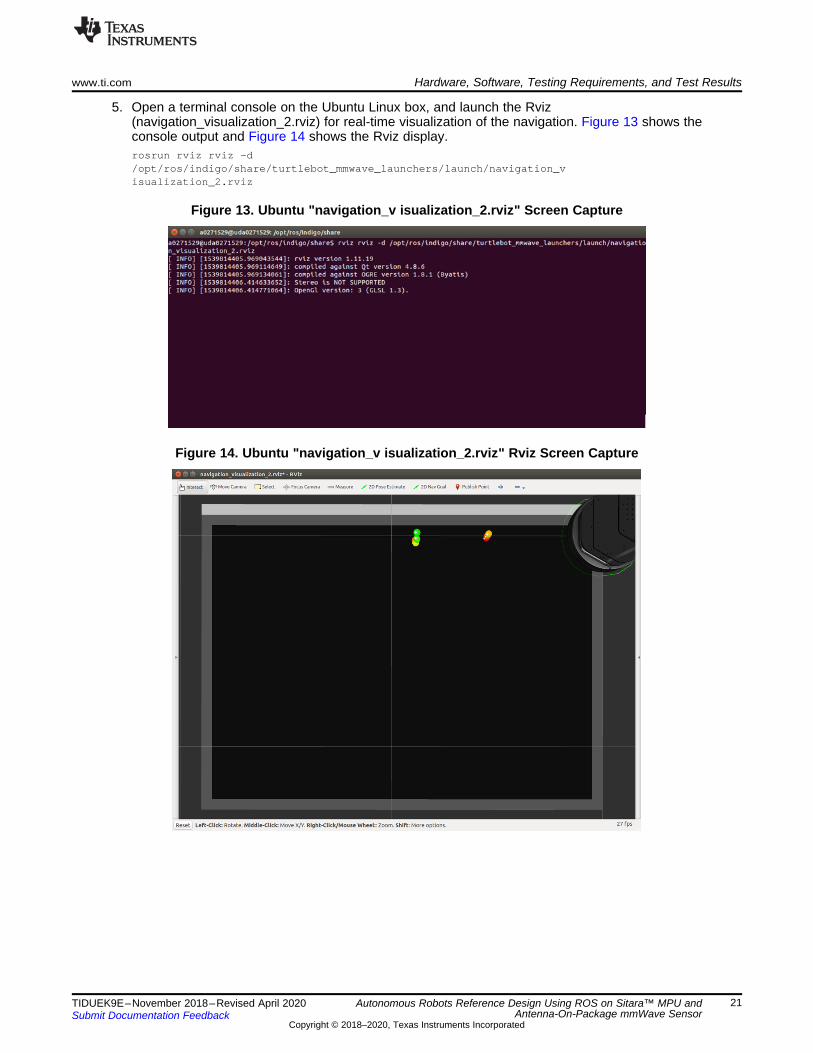
5. Open a terminal console on the Ubuntu Linux box, and launch the Rviz(navigation_visualization_2.rviz) for real-time visualization of the navigation. Figure 13 shows theconsole output and Figure 14 shows the Rviz display.rosrun rviz rviz -d/opt/ros/indigo/share/turtlebot_mmwave_launchers/launch/navigation_visualization_2.rviz
Figure 13. Ubuntu "navigation_v isualization_2.rviz" Screen Capture
Figure 14. Ubuntu "navigation_v isualization_2.rviz" Rviz Screen Capture

Hardware, Software, Testing Requirements, and Test Results www.ti.com
22 TIDUEK9E–November 2018–Revised April 2020Submit Documentation Feedback
Copyright © 2018–2020, Texas Instruments Incorporated
Autonomous Robots Reference Design Using ROS on Sitara™ MPU andAntenna-On-Package mmWave Sensor
6. Start navigation on the AM572x EVM by setting the initial position and the goal to be reachedThe demo uses a pre-defined size 4-by-6 feet map file, with three locations (a, b, and c for top, middle,and bottom, respectively) on each side (left and right).Open the fourth SSH terminal to the AM572xEVM, and set the initial position with the side (left or right) and the location (a, b, or c), and then, setthe location (a, b, or c) on the other side as the goal, by running the scripts below (see Figure 15):source /opt/ros/indigo/setup.bashcd /opt/ros/indigo/share/turtlebot_mmwave_launchers/scripts/./start_nav.sh
First, the Kobuki has the initial left-side middle-point B position set (see Figure 16).Then, the Kobuki navigates to the right-side middle-point B goal (see Figure 17), following the shortestpath available. After it reaches the goal, the Kobuki rotates and faces toward the initial position.If there are objects between the initial position and the goal, the mmWave sensor detects them (shownas red/yellow/green circles in Rviz as in Figure 18). With the radar sensing data, a new path (the thinblue line connecting the initial position and the goal) is found in real-time to avoid the obstacles,demonstrating the "sense and avoid" capability of the autonomous navigation in this reference design(see Figure 18).To re-run the navigation demo, simply specify the starting side/position and the goal position from theconsole of "./start_nav.sh"(see Figure 15).
Figure 15. Sitara "start_nav.sh" Output Screen Capture

www.ti.com Hardware, Software, Testing Requirements, and Test Results
23TIDUEK9E–November 2018–Revised April 2020Submit Documentation Feedback
Copyright © 2018–2020, Texas Instruments Incorporated
Autonomous Robots Reference Design Using ROS on Sitara™ MPU andAntenna-On-Package mmWave Sensor
Figure 16. Ubuntu Rviz Screen Capture - Initial Left-Side Point B Position
Figure 17. Ubuntu Rviz Screen Capture - Right-Side B Point Goal Reached

Hardware, Software, Testing Requirements, and Test Results www.ti.com
24 TIDUEK9E–November 2018–Revised April 2020Submit Documentation Feedback
Copyright © 2018–2020, Texas Instruments Incorporated
Autonomous Robots Reference Design Using ROS on Sitara™ MPU andAntenna-On-Package mmWave Sensor
Figure 18. Ubuntu Rviz Screen Capture - Sense and Avoid
3.2.2.1 Additional Support for mmWave Sensors
3.2.2.1.1 IWR1443Besides the IWR6843ISK (operating within 60- to 64-GHz, which is an open band for most industrialapplications), the Processor SDK Linux also maintains support for the IWR1443 (operating within a 76- to81-GHz band) for autonomous robotics.
To use the IWR1443 with this reference design, on the hardware side, use IWR1443BOOST as themmWave EVM.
For the software when using IWR1443, follow the same procedure described in Section 3.2.2, TestResults but for step 3, set the mmwave_device to "1443" when running the minimal.launch command.roslaunch turtlebot_bringup minimal.launch mmwave_device:=1443
3.2.2.1.2 IWR6843AOP, IWR1843 or updating to the Latest SDKTo add support for IWR6843AOP or IWR1843, or for updating to the latest compatible mmWave SDKsoftware, download and refer to Autonomous Robotics with ROS for mmWave. The lab user's guidecontains instructions for hardware set up of the EVMs as well as details on the latest supported SDK forthe EVMs.

www.ti.com Hardware, Software, Testing Requirements, and Test Results
25TIDUEK9E–November 2018–Revised April 2020Submit Documentation Feedback
Copyright © 2018–2020, Texas Instruments Incorporated
Autonomous Robots Reference Design Using ROS on Sitara™ MPU andAntenna-On-Package mmWave Sensor
For the software, the Processor SDK package is not continuously updated to maintain compatibility for allvariants of mmWave sensors or newer versions of the mmWave SDK. For this reason, users are directedto download the Autonomous Robotics with ROS for mmWave from the mmWave Industrial Toolboxwhere the latest scripts and configuration files for mmWave sensors are maintained. Users will thenreplace the relevant files on the AM57x with those from the mmWave Industrial Toolbox. These steps arefurther detailed below:
Remove the existing files on the AM572x:• Open a new terminal and SSH into the AM57x EVM• Navigate to the existing ti_mmwave_rospkg foldercd/opt/ros/indigo/share/ti_mmwave_rospkg
• Delete the existing cfg folderrm -r cfg
• Navigate to the launch filescd/opt/ros/indigo/share/turtlebot_bringup/launch/includes
• Delete existing robot.launch.xmlrm robot.launch.xml
Add the downloaded files from the Linux machine to the AM572x:• On the Linux machine, download the mmWave Industrial Toolbox and follow Installing ROS and the TI
mmWave ROS Driver in the User's Guide of the autonomous_robotics_ros lab within the toolbox• With the latest autonomous robotics package installed, copy the cfg folder to the AM572xsudo scp -r/home/rosi/catkin_ws/ti_mmwave_ros_map_nav_v1p4/turtlebot/turtlebot/turtlebot_bringup/launch/includes/robot.launch.xml root@am57xxevm:/opt/ros/indigo/share/turtlebot_bringup/launch/includes
• Copy the robot.launch.xml folder to the AM572xsudo scp -r/home/rosi/catkin_ws/ti_mmwave_ros_map_nav_v1p4/turtlebot/turtlebot/turtlebot_bringup/launch/includes/robot.launch.xml root@am57xxevm:/opt/ros/indigo/share/turtlebot_bringup/launch/includes
Continue with the same procedure described in Section 3.2.2, Test Results but for , set themmwave_device to match the desired device when launching the minimal.launch command.• For IWR6843ISKroslaunch turtlebot_bringup minimal.launch mmwave_device:=6843ISK
• For IWR6843AOProslaunch turtlebot_bringup minimal.launch mmwave_device:=6843AOP
• For IWR1843BOOSTroslaunch turtlebot_bringup minimal.launch mmwave_device:=1843
• For IWR1443BOOSTroslaunch turtlebot_bringup minimal.launch mmwave_device:=1443

Design Files www.ti.com
26 TIDUEK9E–November 2018–Revised April 2020Submit Documentation Feedback
Copyright © 2018–2020, Texas Instruments Incorporated
Autonomous Robots Reference Design Using ROS on Sitara™ MPU andAntenna-On-Package mmWave Sensor
4 Design Files
4.1 SchematicsTo download the schematics for the AM572x, see the design files at TIDEP-01006.
4.2 Bill of MaterialsTo download the bill of materials (BOM), see the design files at TIDEP-01006.
5 Software FilesDownload the Processor SDK Linux for AM57x Sitara Processors
Download the mmWave SDK
Download the Autonomous Robotics with ROS for mmWave lab in the Industrial mmWave Toolbox
6 Related Documentation1. IFR Press Release, IFR CEO Roundtable, Munich, Jun 20, 20182. IFR Press Release, Frankfurt, May 30, 20183. Open embedded layer for ROS applications4. Texas Instruments, mmWave sensors: industrial toolbox: labs: ROS point cloud visualizer5. Texas Instruments, mmWave sensors: industrial toolbox: labs: autonomous robotics with ROS for
mmWave6. Texas Instruments, AM572x evaluation module7. Texas Instruments, IWR6843 intelligent mmWave sensor standard antenna plug-in module8. Texas Instruments, mmWave sensors carrier card platform9. iClebo Kobuki10. ROS and radar in processor SDK Linux11. Texas Instruments, mmWave SDK12. Texas Instruments, mmWave training series
6.1 TrademarksSitara, TI E2E are trademarks of Texas Instruments.Arm, Cortex are registered trademarks of ARM Limited (or its subsidiaries) in the EU and/or elsewhere. Allrights reserved.All other trademarks are the property of their respective owners.
6.2 Third-Party Products DisclaimerTI'S PUBLICATION OF INFORMATION REGARDING THIRD-PARTY PRODUCTS OR SERVICES DOESNOT CONSTITUTE AN ENDORSEMENT REGARDING THE SUITABILITY OF SUCH PRODUCTS ORSERVICES OR A WARRANTY, REPRESENTATION OR ENDORSEMENT OF SUCH PRODUCTS ORSERVICES, EITHER ALONE OR IN COMBINATION WITH ANY TI PRODUCT OR SERVICE.

www.ti.com Terminology
27TIDUEK9E–November 2018–Revised April 2020Submit Documentation Feedback
Copyright © 2018–2020, Texas Instruments Incorporated
Autonomous Robots Reference Design Using ROS on Sitara™ MPU andAntenna-On-Package mmWave Sensor
7 Terminology
EVM Evaluation ModuleIFR International Federation of RoboticsISK Industrial Starter KitLTS Long Term SupportPLC Programmable Logic ControllerPLSDK Processor SDK for LinuxPRU Programmable Real-Time UnitROS Robotic Operating SystemSDK Software Development KitSoC System on ChipSSH Secure Socket Shell
8 About the AuthorHongmei Gou is a software engineer with the Catalog Processor Group. She received a Ph.D. degree inelectrical engineering from University of Maryland, College Park, in 2007. Her recent roles focus onProcessor SDK Linux software packages for the Sitara devices, including robotics, machine vision, andindustrial applications.
Djordje Senicic is a senior software engineer with the Catalog Processor Group. His recent roles focuson Processor Linux software packages for Sitara and Keystone devices, including deep learning, robotics,and machine vision applications.

Revision History www.ti.com
28 TIDUEK9E–November 2018–Revised April 2020Submit Documentation Feedback
Copyright © 2018–2020, Texas Instruments Incorporated
Revision History
Revision History
Changes from D Revision (September 2019) to E Revision .......................................................................................... Page
• Added ...for example, the IWR6843AOP, which is a standalone EVM using the IWR6843 Antenna-On-Package, whichminimizes footprint and design complexity as there is no need for antennas on the PCB. ................................... 11
• Added Figure 4: IWR6843AOP ........................................................................................................ 12
Changes from C Revision (July 2019) to D Revision ..................................................................................................... Page
• Changed "IWR6843ISK and IWR6843AOPEVM" to "IWR6843ISK, IWR6843AOPEVM, IWR1443BOOST, orIWR1843BOOST." ........................................................................................................................ 1
• Added IWR1443, or IWR1843 EVM .................................................................................................... 1• Added Other mmWave sensors, including the IWR1443, IWR1843, and IWR6843AOP EVMS, are also supported.
Specifics related to enabling these other supported platforms are detailed in Section 3.2.2.1.2............................... 3• Added IWR1843BOOST ................................................................................................................. 7• Added Update to the latest mmWave drivers: to use the latest mmWave SDK or other mmWave EVMs, see
Section 3.2.2.1.2 .......................................................................................................................... 9• Changed software version.............................................................................................................. 14• Added For other compatible mmWave sensors, this step will differ. Refer to Section 3.2.2.1.2 for additional steps required
to enable support for other mmWave EVMs. ........................................................................................ 18• Changed "IWR6843AOP and Latest SDK" to "IWR6843AOP, IWR1843 or updating to the Latest SDK"................... 24• Added IWR1843 ......................................................................................................................... 24• Added paragraph ........................................................................................................................ 25
Changes from B Revision (June 2019) to C Revision .................................................................................................... Page
• Changed title from "Autonomous robotics reference design with Sitara™ Processor and mmWave Sensors using ROS" to"Autonomous Robots Reference Design Using ROS on Sitara™ MPU and Antenna-On-Package mmWave Sensor" .... 1
• Changed "IWR6843" to "IWR6843ISK and IWR6843AOPEVM".................................................................... 1• Added sentence: In addition, it also supports the IWR6843 antenna-on-package variant of mmWave sensors which
enables reduced design and manufacturing cost, simplified system design, smaller sensor footprint, and eventually fastertime to market. ............................................................................................................................ 1
• Added Integration with IWR6843AOPEVM enables a 130º FOV coverage in both azimuth and elevation to enable smarterdecision making based on object height. .............................................................................................. 1
• Deleted mmWave radar sending and seamlessly communicating with AM57x processor over ROS ......................... 1• Deleted the Autonomous Robotics with ROS for mmWave lab in the Industrial mmWave Toolbox ......................... 24
Changes from A Revision (January 2019) to B Revision ............................................................................................... Page
• Changed IWR6843ISK to IWR6843 .................................................................................................... 1• Added IWR6843AOPEVM ............................................................................................................... 1• Changed paragraph adding additional information ................................................................................... 2• Changed "...and this solution enables unprecedented levels of integration in an extremely small form factor." to "... to
integrate analog RF as well as digital processing in a single chip." ................................................................ 4• Added Option for integration of 4 receiver and 3 transmitter antenna-on-package (AOP) ..................................... 4• Added ARM-R4F microcontroller for object detection, and interface control ..................................................... 4• Added Supports autonomous mode (loading user application from QSPI flash memory)....................................... 4• Added C674x DSP for advanced signal processing (IWR6843 or IWR6843 AOP only) ........................................ 4• Deleted IWR1443 mmWave radar sensing ............................................................................................ 6• Added Alternatively, the IWR6843ISK and mmWaveICBOOST boards can be interchanged for other compatible mmWave
sensors. Refer to Section 3.2.2.1 for additional steps required to enable support for other mmWave EVMs. ............. 11• Changed IWR6843ISK to WR6843ISK ............................................................................................... 13

www.ti.com Revision History
29TIDUEK9E–November 2018–Revised April 2020Submit Documentation Feedback
Copyright © 2018–2020, Texas Instruments Incorporated
Revision History
• Added text regarding the EVM User's Guide and mmWave SDK ................................................................ 14• Changed subsection title from "For IWR1443 User Support" to "Additional Support for mmWave Sensors ................ 24• Added new section for IWR1443 ...................................................................................................... 24• Added IWR6843AOP and Latest SDK subsection .................................................................................. 24• Added Autonomous Robotics with ROS for mmWave lab in the Industrial mmWave Toolbox link........................... 26
Changes from Original (November 2018) to A Revision ................................................................................................ Page
• Changed to reflect the key features for the IWR6843 mmWave sensor. .......................................................... 4• Added sentence with move_base change details..................................................................................... 8• Added ROS Packages; changed the Yocto recipe example to be a generalized [version] ..................................... 9• Changed this section to detail the IWR6843ISK and MMWAVEICBOOST boards within the mmWave EVM Hardware.. 11• Changed paragraph to include the correct mmWave SDK version which supports IWR6843 ................................ 14• Changed sentence stating the Ubuntu version used for verifying this reference design ...................................... 14• Changed paragraph to discuss the mounting of the IWR6843ISK and MMWAVEICBOOST boards to the Kobuki ....... 14• Changed the hardware setup to include the mounting of the IWR6843ISK and MMWAVEICBOOST boards to the Kobuki
............................................................................................................................................. 14• Added the copying of the kobuki_description directory from target to Ubuntu .................................................. 16• Changed the code example command line to include the specific device (6843) .............................................. 18• Changed the screen captures (beginning and end) to show usage with IWR6843............................................. 18• Added new subsection to support any IWR1443 users ............................................................................ 24• Changed the specified ulink ........................................................................................................... 26• Changed the "IWR1443" evaluation module reference to the mmWave sensor standard plug-in module for the "IWR6843"
and updated the ulink ................................................................................................................... 26• Changed the ulink for the TI mmWave ROS Driver................................................................................. 26• Changed the ulink for the TI Autonomous Robotics with ROS for mmWave .................................................... 26• Changed mmWave sensors carrier card platform (MMWAVEICBOOST) title along with the ulink........................... 26• Changed the term "ISK" to this section ............................................................................................... 27• Changed sequence order terms to be alphabetical ................................................................................. 27

IMPORTANT NOTICE AND DISCLAIMER
TI PROVIDES TECHNICAL AND RELIABILITY DATA (INCLUDING DATASHEETS), DESIGN RESOURCES (INCLUDING REFERENCE DESIGNS), APPLICATION OR OTHER DESIGN ADVICE, WEB TOOLS, SAFETY INFORMATION, AND OTHER RESOURCES “AS IS” AND WITH ALL FAULTS, AND DISCLAIMS ALL WARRANTIES, EXPRESS AND IMPLIED, INCLUDING WITHOUT LIMITATION ANY IMPLIED WARRANTIES OF MERCHANTABILITY, FITNESS FOR A PARTICULAR PURPOSE OR NON-INFRINGEMENT OF THIRD PARTY INTELLECTUAL PROPERTY RIGHTS.These resources are intended for skilled developers designing with TI products. You are solely responsible for (1) selecting the appropriate TI products for your application, (2) designing, validating and testing your application, and (3) ensuring your application meets applicable standards, and any other safety, security, or other requirements. These resources are subject to change without notice. TI grants you permission to use these resources only for development of an application that uses the TI products described in the resource. Other reproduction and display of these resources is prohibited. No license is granted to any other TI intellectual property right or to any third party intellectual property right. TI disclaims responsibility for, and you will fully indemnify TI and its representatives against, any claims, damages, costs, losses, and liabilities arising out of your use of these resources.TI’s products are provided subject to TI’s Terms of Sale (www.ti.com/legal/termsofsale.html) or other applicable terms available either on ti.com or provided in conjunction with such TI products. TI’s provision of these resources does not expand or otherwise alter TI’s applicable warranties or warranty disclaimers for TI products.
Mailing Address: Texas Instruments, Post Office Box 655303, Dallas, Texas 75265Copyright © 2020, Texas Instruments Incorporated