Autonomous Monitoring Framework with Fallen Person Pose …jun/pdffiles/igi-icitee2014.pdf ·...
6
Autonomous Monitoring Framework with Fallen Person Pose Estimation and Vital Sign Detection Igi Ardiyanto, Junji Satake, and Jun Miura Department of Computer Science and Engineering Toyohashi Unversity of Technology Aichi, Japan Email: {iardiyanto, jun}@aisl.cs.tut.ac.jp Abstract—This paper describes a monitoring system based on the cooperation of a surveillance sensor and a mobile robot. Using a depth camera which acts as the surveillance sensor, the system estimates the pose and orientation of a person utilizing a skeleton-based algorithm. When the person fell down, the sensor sends the person’s pose and orientation information to the mobile robot. The robot determines the possible movements and strategies for reaching the fallen person. The robot then approaches the person and checks the vital condition whether the person is breathing, and the recognition result is notified to a hand-held device. Experiments on our monitoring system confirm a successful series of the autonomous operations. I. I NTRODUCTION In Japan, aging society has become a challenge where the number of elder populations are more than the young generations. Such condition has raised many problems. We take an example in a nursing home which has unbalanced number of the staff in charges and the staying elders. The staff may not be able to continuously watch each elder people. Due to the physical limitations, there are some occasions where an elder person fell down in the daily life at the nursing home. While the fell down cases may only cause a minor effect to the young people, for the elder person it can give a serious injury. The staff of the nursing home may fail to notice the fallen elder immediately, whereas a late handling of these situations can lead to collateral or even major damages to the elder person. Many works and systems have been proposed for coping with the fallen person problem. The works mainly can be divided into two approaches, intrusive and non-intrusive [1]. The intrusive approach demands the elder person for wearing a device, such as an accelerometer [2], to detect the fall down event. This approach becomes troublesome, especially for the elder with dementia symptom [1] which may forget to wear or store the device. As the opposite, the non-intrusive approach uses external sensors to detect the fall down event, including some works using multiple cameras [3] or depth data (e.g. [4], [5], and [6]). Unfortunately, none of these works considers a further applied action for the fallen person, except just notifies the other persons via sound alarm such as in [3]. Another drawback of these works is the lack of information accommodated by their systems, where they do not even provide the fallen person position data relative to the environment ([2], [3], and [6]). Fig. 1: Monitoring system framework with a surveillance sensor and an autonomous robot. For dealing with such shortcoming, here we propose a comprehensive monitoring system employing the cooperation between a surveillance sensor and a mobile robot (see Fig. 1). A Kinect-based surveillance sensor serves as the fallen person detector. Our system estimates both pose location and orientation of the fallen person’s head, enabling a further response by the autonomous robot. The mobile robot is then engaged to check the fallen person vital and condition whenever it receives the information about the fallen event from the surveillance sensor. Here a CO 2 sensor-based breath detection is used as the vital sign. Together with the Kinect video streams, the sensor data is sent to the server real-time so that the third party person (e.g. the staff) knows what is happening and how severe the fallen person condition. Contributions of this paper are two-fold. First, the system provides an extensive autonomous framework for an indoor monitoring, ranging from the falling person detection to the further responses (i.e. performs the vital measurement) after the fallen event. Therefore, unlike the aforementioned other works, our fallen person detection serves both position and orientation of the person, makes it easier for the robot to locate and do the vital measurement in response to the incident. The rest of this paper is organized as follows. In section II we establish the system architecture of the monitoring system. A strategy for estimating the pose and orientation of the fallen person is presented in section III. Section IV explains the
Transcript of Autonomous Monitoring Framework with Fallen Person Pose …jun/pdffiles/igi-icitee2014.pdf ·...

Autonomous Monitoring Framework with FallenPerson Pose Estimation and Vital Sign Detection
Igi Ardiyanto, Junji Satake, and Jun MiuraDepartment of Computer Science and Engineering
Toyohashi Unversity of TechnologyAichi, Japan
Email: {iardiyanto, jun}@aisl.cs.tut.ac.jp
Abstract—This paper describes a monitoring system basedon the cooperation of a surveillance sensor and a mobile robot.Using a depth camera which acts as the surveillance sensor, thesystem estimates the pose and orientation of a person utilizinga skeleton-based algorithm. When the person fell down, thesensor sends the person’s pose and orientation information tothe mobile robot. The robot determines the possible movementsand strategies for reaching the fallen person. The robot thenapproaches the person and checks the vital condition whetherthe person is breathing, and the recognition result is notified to ahand-held device. Experiments on our monitoring system confirma successful series of the autonomous operations.
I. INTRODUCTION
In Japan, aging society has become a challenge wherethe number of elder populations are more than the younggenerations. Such condition has raised many problems. Wetake an example in a nursing home which has unbalancednumber of the staff in charges and the staying elders. The staffmay not be able to continuously watch each elder people.
Due to the physical limitations, there are some occasionswhere an elder person fell down in the daily life at the nursinghome. While the fell down cases may only cause a minoreffect to the young people, for the elder person it can give aserious injury. The staff of the nursing home may fail to noticethe fallen elder immediately, whereas a late handling of thesesituations can lead to collateral or even major damages to theelder person.
Many works and systems have been proposed for copingwith the fallen person problem. The works mainly can bedivided into two approaches, intrusive and non-intrusive [1].The intrusive approach demands the elder person for wearinga device, such as an accelerometer [2], to detect the fall downevent. This approach becomes troublesome, especially for theelder with dementia symptom [1] which may forget to wearor store the device.
As the opposite, the non-intrusive approach uses externalsensors to detect the fall down event, including some worksusing multiple cameras [3] or depth data (e.g. [4], [5], and [6]).Unfortunately, none of these works considers a further appliedaction for the fallen person, except just notifies the otherpersons via sound alarm such as in [3]. Another drawbackof these works is the lack of information accommodated bytheir systems, where they do not even provide the fallen personposition data relative to the environment ([2], [3], and [6]).
Fig. 1: Monitoring system framework with a surveillance sensor and anautonomous robot.
For dealing with such shortcoming, here we propose acomprehensive monitoring system employing the cooperationbetween a surveillance sensor and a mobile robot (see Fig.1). A Kinect-based surveillance sensor serves as the fallenperson detector. Our system estimates both pose location andorientation of the fallen person’s head, enabling a furtherresponse by the autonomous robot.
The mobile robot is then engaged to check the fallen personvital and condition whenever it receives the information aboutthe fallen event from the surveillance sensor. Here a CO2
sensor-based breath detection is used as the vital sign. Togetherwith the Kinect video streams, the sensor data is sent to theserver real-time so that the third party person (e.g. the staff)knows what is happening and how severe the fallen personcondition.
Contributions of this paper are two-fold. First, the systemprovides an extensive autonomous framework for an indoormonitoring, ranging from the falling person detection to thefurther responses (i.e. performs the vital measurement) afterthe fallen event. Therefore, unlike the aforementioned otherworks, our fallen person detection serves both position andorientation of the person, makes it easier for the robot to locateand do the vital measurement in response to the incident.
The rest of this paper is organized as follows. In section IIwe establish the system architecture of the monitoring system.A strategy for estimating the pose and orientation of the fallenperson is presented in section III. Section IV explains the
jun
タイプライターテキスト
Proc. 6th Int. Conf. on Information Technology and Electrical Engineering, 2014.

Fig. 2: Monitoring system architecture.
coordination between the surveillance sensor and the robotfor measuring the vital sign of the person. We then verify theexperiment results in section V. Lastly, we give the conclusionand some possible future directions of this work.
II. SYSTEM ARCHITECTURE
This section describes the overall framework of our mon-itoring system. The primary idea is to immediately take aresponse when a fallen incident occurs, by sending a robotto check the vital sign of the person. Here, our system is thendivided into two major parts: the fallen person pose estimation,and the vital sign measurement by the robot.
The fallen person estimation is carried out by a Kinectcamera which is set on the ceiling of the room. This camerais responsible to detect the person, calculate the head positionand its orientation, and then send the information to the robot.An accurate estimation of the person’s head location andorientation becomes inevitable, especially for locating the nose,as we use the person’s breath as the vital sign. The detail ofthese processes will be further explained in the section III.
Subsequently, a robot which is stood by a certain location(it may be located at a different room) and equipped by alaser range and a CO2 sensor, will use the information fromthe Kinect camera to navigate towards the fallen person. Thegoal is to put the CO2 sensor attached in front of the robotbody as close as possible to the head of the fallen person formeasuring the breath. A sequence of motion strategy, whichwill be described in the section IV, is then performed by therobot to realize the task above.
Both parts interchange the data through a server usingsocket-based communication. The entire data of the fallenperson and vital sign, including the CO2 sensor reading, videostreams from the camera, and the robot state, can be accessedusing a hand-held device (e.g. smart phone and tablet) viawebsocket protocol [7], to be used by the third-party person.Figure 2 shows the architecture of our monitoring system.
Fig. 3: Calibrating the camera. The red, blue, and green lines show the origincoordinate of the world frame. The yellow grids are the estimated groundplane (it will be translated to the origin and scaled in the experiments).
III. FALLEN PERSON POSE ESTIMATION USING A DEPTHCAMERA
Unlike the other works on the fallen person detection whichonly care whether there is any fallen person event or not,our main concern is to precisely estimate the person locationand its orientation. It is a compulsory requirement as theinformation will be used by an autonomous mobile robot forfurther action (i.e. measures the person’s breath). Here wepropose a Kinect-based person estimation system for solvingthose problems.
A. Calibrating Parameter of The Kinect Camera
The first step for achieving an accurate person pose es-timation is to have a decent calibrated camera. Assuming apinhole camera model for the Kinect, let xw = {xw, yw, zw}and xc = {xc, yc, zc} be a 3D point coordinate in the worldframe and its corresponding coordinate in the camera space.Transformation of both frames are given by
xc = Rxw + t, (1)
where R and t respectively denote the extrinsic parameters,i.e. the rotation matrix and translation vector.
The Kinect also holds the ordinary RGB data. By lettingx = {u, v} be the coordinate of the projection point in theimage, the pinhole projection can be expressed by
x ∼ A[R t]xw,
A =
[fu 0 cu0 fv cv0 0 1
],
(2)
where A is the intrinsic parameters of the camera, fu and fvdenote the focal lengths in each axis, and cu and cv representthe optical center in the image plane. The skew and lensdistortion are neglected in our case. The intrinsic matrix A isobtained using a standard camera calibration algorithm from[8]. Since the Kinect provides the depth information (i.e. zc),relation between the image and depth map can be describedas
xc = zcu− cufu
,
yc = zcv − cvfv
.(3)

Fig. 4: Modeling the human skeleton. The yellow grids are the estimatedground plane. The thin red line represents the head pose and orientation, andits projection on the ground is shown by the bold red line. The joints insidethe blue circle are used for the pose estimation.
To get the extrinsic parameters, a chessboard pattern isutilized (see Fig. 3) from which a set of corner point isthen retrieved for estimating the chessboard pose and itscorresponding projection in the Kinect space. This problemis solved using perspective-n-points method [9]. The obtainedR and t are then used for the coordinate transformation in thepose estimation.
B. Fallen Person Detection and Its Pose Estimation
The use of the depth map has many advantages as itprovides a real 3D scene representation. For example, a workfrom [10] shows that by using a depth map, the body skeletonof a person can be extracted in real-time. Here we adopt theirwork by using the skeletal extraction as a base of our fallenperson detection and its pose estimation.
Given S = {s0, s1, . . . , sk} as the skeletal joints of thebody obtained by the Kinect camera when a person entersthe camera view, therefore let Sup = {sh, ssr, ssl} ⊂ S be theupper head, right shoulder, and left shoulder joints respectively.In the Kinect frame, the point coordinate of each s ∈ Sup isthen described as xsc = {xsc, ysc , zsc}. Using previously obtainedR and t, xsc is projected to the world coordinate as follows
xsw = R−1(xsc − t) for {∀s ∈ Sup}, (4)
where xsw = {xsw, ysw, zsw} is the world coordinate point ofeach s ∈ Sup. Figure 4 shows the skeletal modeling of thehuman.
The center of the head position xchw can be estimated byaveraging the upper head and both shoulder joint poses,
xchw =1
|Sup|∑∀s∈Sup
xsw, (5)
where |Sup| is the cardinality of the set Sup (hence, |Sup| = 3).The fallen event is then simply detected using the value ofzchw (the z-component of xchw ). If zchw less than a designatedthreshold, it means the head is near the ground plane and willbe categorized as a fallen person event.
Fig. 5: Locating the robot goal in front of the head. The bold red dot is therobot expected goal for measuring the person’s breath.
Therefore, we need to project the head pose to the groundplane (i.e. z-axis= 0) on which the robot moves. Anotherconsideration is the assigned head position should hold somedistances in front of the head (of course, the robot should nothit the person’s head).
Let xphw = {xphw , yphw , 0} denote the projected head positionon the ground plane with an additional distance, on which therobot will safely stop to measure the person’s breath (see Fig.5). We then derive xphw as follows
xphw = xchw +δ
||xc||xc, (6)
where
xc = xa × xb,xa = xssrw − xshw ,xb = xsslw − xshw .
(7)
xssrw , xsslw , and xshw are respectively the joint position of theright shoulder, left shoulder, and upper head as pointed out ineq. 4, and δ is a relative distance between the projected headpose and the expected robot target (currently, δ = 70 cm).Accordingly, the person orientation θ is calculated by
sgn(θ) = tan−1(yphw − ychwxphw − xchw
), (8)
where (xchw , ychw ) ∈ xchw , (xphw , yphw ) ∈ xphw , and sgn(θ)
indicates the robot goal has an opposite direction to the personorientation. Now, we have xgoal
w = {xphw , yphw , θ} as the giventarget pose for the robot to measure the person vital condition.
IV. MANAGING THE ROBOT MOTION FOR MEASURINGTHE HUMAN VITAL SIGN
After a fallen person has been detected by the Kinect sys-tem, a prompt response needs to be conducted for encounteringthe incident. Here, a mobile robot is utilized for approachingthe person location and measuring the vital sign which will bethe base of the next action for the victim.
As the robot is initially placed in a certain room whichmay differ with the fallen person location, the robot movementfor accomplishing the tasks needs to be decomposed. A FiniteState Machine-based robot movement strategy is then proposedfor handling this problem.
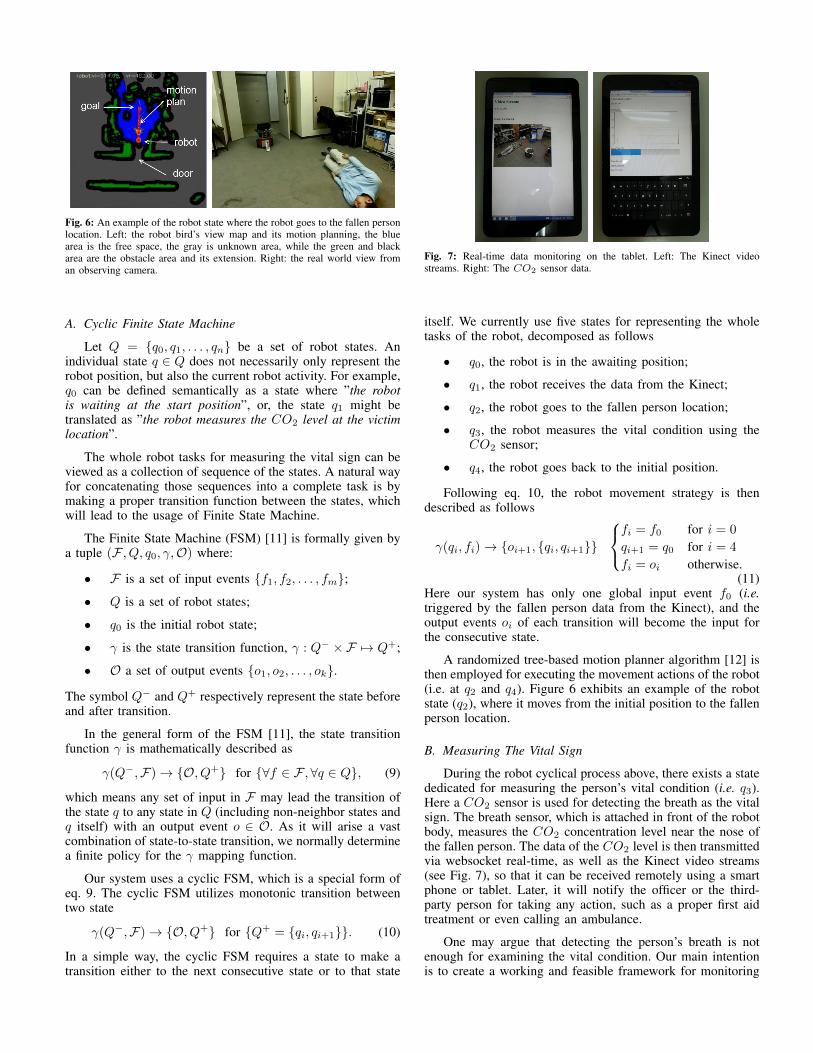
Fig. 6: An example of the robot state where the robot goes to the fallen personlocation. Left: the robot bird’s view map and its motion planning, the bluearea is the free space, the gray is unknown area, while the green and blackarea are the obstacle area and its extension. Right: the real world view froman observing camera.
A. Cyclic Finite State Machine
Let Q = {q0, q1, . . . , qn} be a set of robot states. Anindividual state q ∈ Q does not necessarily only represent therobot position, but also the current robot activity. For example,q0 can be defined semantically as a state where ”the robotis waiting at the start position”, or, the state q1 might betranslated as ”the robot measures the CO2 level at the victimlocation”.
The whole robot tasks for measuring the vital sign can beviewed as a collection of sequence of the states. A natural wayfor concatenating those sequences into a complete task is bymaking a proper transition function between the states, whichwill lead to the usage of Finite State Machine.
The Finite State Machine (FSM) [11] is formally given bya tuple (F , Q, q0, γ,O) where:
• F is a set of input events {f1, f2, . . . , fm};
• Q is a set of robot states;
• q0 is the initial robot state;
• γ is the state transition function, γ : Q− ×F 7→ Q+;
• O a set of output events {o1, o2, . . . , ok}.
The symbol Q− and Q+ respectively represent the state beforeand after transition.
In the general form of the FSM [11], the state transitionfunction γ is mathematically described as
γ(Q−,F)→ {O, Q+} for {∀f ∈ F ,∀q ∈ Q}, (9)
which means any set of input in F may lead the transition ofthe state q to any state in Q (including non-neighbor states andq itself) with an output event o ∈ O. As it will arise a vastcombination of state-to-state transition, we normally determinea finite policy for the γ mapping function.
Our system uses a cyclic FSM, which is a special form ofeq. 9. The cyclic FSM utilizes monotonic transition betweentwo state
γ(Q−,F)→ {O, Q+} for {Q+ = {qi, qi+1}}. (10)
In a simple way, the cyclic FSM requires a state to make atransition either to the next consecutive state or to that state
Fig. 7: Real-time data monitoring on the tablet. Left: The Kinect videostreams. Right: The CO2 sensor data.
itself. We currently use five states for representing the wholetasks of the robot, decomposed as follows
• q0, the robot is in the awaiting position;
• q1, the robot receives the data from the Kinect;
• q2, the robot goes to the fallen person location;
• q3, the robot measures the vital condition using theCO2 sensor;
• q4, the robot goes back to the initial position.
Following eq. 10, the robot movement strategy is thendescribed as follows
γ(qi, fi)→ {oi+1, {qi, qi+1}}
fi = f0 for i = 0
qi+1 = q0 for i = 4
fi = oi otherwise.(11)
Here our system has only one global input event f0 (i.e.triggered by the fallen person data from the Kinect), and theoutput events oi of each transition will become the input forthe consecutive state.
A randomized tree-based motion planner algorithm [12] isthen employed for executing the movement actions of the robot(i.e. at q2 and q4). Figure 6 exhibits an example of the robotstate (q2), where it moves from the initial position to the fallenperson location.
B. Measuring The Vital Sign
During the robot cyclical process above, there exists a statededicated for measuring the person’s vital condition (i.e. q3).Here a CO2 sensor is used for detecting the breath as the vitalsign. The breath sensor, which is attached in front of the robotbody, measures the CO2 concentration level near the nose ofthe fallen person. The data of the CO2 level is then transmittedvia websocket real-time, as well as the Kinect video streams(see Fig. 7), so that it can be received remotely using a smartphone or tablet. Later, it will notify the officer or the third-party person for taking any action, such as a proper first aidtreatment or even calling an ambulance.
One may argue that detecting the person’s breath is notenough for examining the vital condition. Our main intentionis to create a working and feasible framework for monitoring

Fig. 8: Person pose and orientation estimation results.
system. Or, in other words, measuring the breath is just anexample used in our architecture for detecting the vital. Addi-tional methods for the measuring the vital sign can be easilyadopted into the system. We will also give some insightfulconsideration about this matter at the last of this paper.
V. EXPERIMENT RESULTS
The proposed framework has been tested in the real worldusing a Pioneer-3DX robot equipped by a laser range finderand a ZMP CO2 sensor, and a Kinect camera attached on theceiling of a room. The implementation of the fallen personestimation is done on a Windows PC (i7 2.4 GHz, 16 GBRAM), while another PC (Core2Duo 2GHz, 2GB RAM) iscarried by the robot for executing the motion control andmeasuring the vital sign. A Windows tablet is then used formonitoring both sensor data and the Kinect output. The entiresystems are realized using C++ and HTML.
First, performance of the human pose and orientationestimation is evaluated. Figure 8 shows the detection andestimation results of the person in various poses, which isqualitatively correct for both pose and orientation. It indicatesthe robustness of our human pose and orientation estimation.These results are quantitatively supported by table I.
TABLE I: Performance of the pose and orientation estimation
Mean Std. Dev.
Distance of projected pose to head (in cm) 66.5 15.6
Orientation error to head (in degrees) 5.0 8.26
Table I shows the projected head position in the groundplane to the original head pose and its orientation error results
Fig. 9: Result of CO2 measurement from the breath detection over the time.The blue range is the result when the robot measures the person’s breath.
of 20 different poses (six poses are displayed in Fig. 8).Compared to ”the distance to head” we have set in sectionIII-B (i.e. 70 cm), the result on table I is relatively favorable.The orientation error is also small, make it possible to be givento the robot as the position for measuring the person’s breath.
Subsequently, we examine the overall performance of ourmonitoring system. Figure 9 and 10 demonstrate a compre-hensive real world experiment. In Fig. 10, the robot whichis stationed outside the room, receives the fallen person datafrom the Kinect. The robot then goes to the front of theperson’s head and measures the breath. Figure 9 shows theCO2 sensor performance during the vital measurement. Whenthe robot stops to do the vital (breath) measurement as pointedby the blue dots, the sensor value significantly increases,indicating that the person still alive. The measurement resultsare transmitted to the server real-time so that it can be readby the other person using the hand-held device. After finishingthe measurement, the robot goes back to its initial position.
We conduct five-fold experiments and all of them aresuccessful, which means the robot correctly follows all of thestate sequences mentioned above without any collision with theenvironment nor the fallen person. One notable thing is thatthe CO2 sensor has a relatively slow response to the change ofthe CO2 concentration in the air. As shown in our experiments(Fig. 9), it needs at least one minute to correctly measure thebreath condition.
Lastly, the cooperation between the Kinect and the robotduring the real experiments is also investigated. We measurethe difference between the fallen person pose given by theKinect and the executed pose by the robot, which is shown bytable II.
TABLE II: Pose differences between the Kinect and the robot
Experiments
#1 #2 #3 #4 #5
Pose differences (in cm) 10.5 9.0 16.5 12.5 10.0
Out of five experiments shown in table II, the maximumdifference between the human pose given by the Kinect and

00:20 00:31
00:38 01:36
01:42 01:49
Fig. 10: Screenshot of experiments showing the sequences of the monitoring framework with the minute-second time frame (mm:ss). The left figure shows theKinect’s view, the center one shows the robot bird’s view map and its motion planning, and the right figure shows the view from an observing camera.
the one executed by the robot is 16.5 cm. We consider theseerrors are due to uncertainty of the robot pose. In comparisonwith the given distance to the head (see table I), these errorsare enough for the robot to not collide with the person’s head.
VI. CONCLUSION
A framework of cooperation between a surveillance sensorand a mobile robot for an indoor monitoring system has beenestablished. Here, a Kinect-based detector successfully givesthe head position and orientation information of the fallenperson to the robot. Once the robot receives the information,it goes to the person location, performs a vital sign analysis,and report the person condition via web server.
While the experiments show remarkable results, someconsiderations need to be further investigated. First, the useof CO2 sensor for the vital sign detection (in this case, thebreath), of course, is practically not enough. Some other vitalsigns, e.g. heartbeat, blood pressure, and bone fractures orinjury detection may be incorporated to the framework. Sec-ondly, the actual pose of the person in the real situation mightbe very difficult to be detected. There are some occasions that afallen person ends up in unnatural poses. A more sophisticatedperson detection system should be contemplated to handlethese problems, especially the one which considers the bodyparts of the person.
REFERENCES
[1] G. Ward, N. Holliday, S. Fielden, and S. Williams. “Fall detectors: areview of the literature”. Journal of Assistive Technologies, vol. 6 (3),pp. 202-215, 2012.
[2] T. Zhang, J. Wang, L. Xu, and P. Liu. “Fall Detection by Wearable Sensorand One-Class SVM Algorithm”. In Int. Conf. on Intelligent Computing,pp. 858-863, 2006.
[3] E. Auvinet, F. Multon, A. Saint-Arnaud, J. Rousseau, and J. Meunier.“Fall Detection With Multiple Cameras: An Occlusion-Resistant MethodBased on 3-D Silhouette Vertical Distribution”. IEEE Trans. on Infor-mation Technology in Biomedicine, vol. 15 (2), pp. 290-300, 2011.
[4] M. Volkhardt, F. Schneemann, and H. Gross. “Fallen Person Detectionfor Mobile Robots using 3D Depth Data”. In IEEE Int. Conf. on Systems,Man, and Cybernetics, pp. 3573-3578, 2013.
[5] G. Mastorakis and D. Makris. “Fall detection system using Kinect’sinfrared sensor”. Journal of Real-Time Image Processing, 1861-8219,2012.
[6] C. Rougier, E. Auvinet, J. Rousseau, M. Mignotte, and J. Meunier. “FallDetection from Depth Map Video Sequences”. In Int. Conf. on SmartHomes and Health Telematics, pp. 121-128, 2011.
[7] I. Fette and A. Melnikov. “The Websocket Protocol”. Internet Engineer-ing Task Force (IETF), pp. 1-71, 2011.
[8] Z. Zhang. “A Flexible New Technique for Camera Calibration”. IEEETrans. on Pattern Analysis and Machine Intelligence, vol. 22 (11), pp.1330-1334, 2000.
[9] V. Lepetit, F. Moreno-Noguer, and P. Fua. “EPnP: An accurate O(n)solution to the pnp problem”. Int. Journal of Computer Vision, vol. 81,pp. 155-166, 2009.
[10] J. Shotton, A. Fitzgibbon, M. Cook, T. Sharp, M. Finocchio, R. Moore,A. Kipman, and A. Blake. “Real-time human pose recognition in partsfrom single depth images”. In IEEE Conf. on Computer Vision andPattern Recognition, pp. 1297-1304, 2011.
[11] T. Koshy. “Discrete Mathematics with Applications”. Academic Press,2004.
[12] I. Ardiyanto and J. Miura. “Real-time navigation using randomizedkinodynamic planning with arrival time field”. Robotics and AutonomousSystems, vol. 60 (12), pp. 1579-1591, 2012.