
Automation Control Standards - etenders.gov.za. Transnet...Transnet Automation Standards Page 3 of...
113
Rev0.95 Transnet Automation Control Standards
Transcript of Automation Control Standards - etenders.gov.za. Transnet...Transnet Automation Standards Page 3 of...
1
Rev0.95
Transnet Automation Control Standards

Transnet Automation Standards
Page 2 of 113
CONTENTS
Contents ............................................................................................................................................................................ 2 Revision control ................................................................................................................................................................. 6 Scope of work.................................................................................................................................................................... 7
Introduction .................................................................................................................................................................... 7 Scope definition ............................................................................................................................................................. 7 Specific exclusions ........................................................................................................................................................ 7
SCADA System Overview ................................................................................................................................................. 8 Architecture.................................................................................................................................................................... 8
Plant Information System Architecture ...................................................................................................................... 8 SCADA Hardware ...................................................................................................................................................... 8 Interface Hardware .................................................................................................................................................... 8 Software ..................................................................................................................................................................... 9
Network .......................................................................................................................................................................... 9 Production Plant System Architecture ........................................................................................................................... 9
Users ........................................................................................................................................................................ 10 Environment ............................................................................................................................................................. 10 Hardware.................................................................................................................................................................. 10 Supervisory Computer Hardware ............................................................................................................................ 10 Software ................................................................................................................................................................... 11
Performance ................................................................................................................................................................ 11 Data Update ............................................................................................................................................................. 11 Screen Display ......................................................................................................................................................... 11
PLC System Overview .................................................................................................................................................... 12 Architecture.................................................................................................................................................................. 12
PLC Hardware ......................................................................................................................................................... 12 Interface Hardware .................................................................................................................................................. 12 Software ................................................................................................................................................................... 12
Network ........................................................................................................................................................................ 12 Users ........................................................................................................................................................................ 13 Environment ............................................................................................................................................................. 13
Software Structure ....................................................................................................................................................... 13 Tasks ........................................................................................................................................................................ 14
Master Template Library .............................................................................................................................................. 15 Coding Standards .................................................................................................................................................... 16 Sequence Logic ....................................................................................................................................................... 16 Group Logic ............................................................................................................................................................. 16 System Logic ........................................................................................................................................................... 16 IO Control and Topologies ....................................................................................................................................... 16 Watchdog Procedure ............................................................................................................................................... 17 General Watchdog Practice ..................................................................................................................................... 17 Naming Convention of Watchdogs .......................................................................................................................... 17 Identification of Devices ........................................................................................................................................... 17 IO Scanning ............................................................................................................................................................. 17 Heartbeat ................................................................................................................................................................. 18 IO Scanning Health Bit ............................................................................................................................................. 18 IO Scanning Watchdog Fail Bit ................................................................................................................................ 18 Global Data .............................................................................................................................................................. 18 Heartbeat ................................................................................................................................................................. 19 Global Data Health Bit ............................................................................................................................................. 19 Global Data Watchdog Fail Bit ................................................................................................................................. 19 Philosophy ............................................................................................................................................................... 19
ArchestrA Database Configuration ................................................................................................................................. 20 Tag Naming Convention .............................................................................................................................................. 20
Area / Plant .............................................................................................................................................................. 20 I/O Tag ..................................................................................................................................................................... 21 Local Variable or Memory Tag ................................................................................................................................. 21
Transnet Automation Standards
Page 3 of 113
Device Integration (D/I) Object Naming ....................................................................................................................... 22 Human Machine Interface Configuration ........................................................................................................................ 23
Design Standard .......................................................................................................................................................... 23 Window Format ........................................................................................................................................................... 23
Window Configuration and Size ............................................................................................................................... 24 Customised Screen Format ......................................................................................................................................... 24
Area 1: Alarm Summary and General commands (Banner) ................................................................................... 24 Area 2: Navigation Area .......................................................................................................................................... 25 Area 3 and 4: Application Screen Window ............................................................................................................. 25 Area 4: Context sensitive control area (optional) ..................................................................................................... 26
Screen Hierarchy ......................................................................................................................................................... 26 Screen Selection ......................................................................................................................................................... 28
Window and Sub-window Selection ......................................................................................................................... 28 Graphic Screen Naming Convention ........................................................................................................................... 28 Process Display Colour Definition ............................................................................................................................... 29 Common functions ....................................................................................................................................................... 29
Control Buttons Functionality ................................................................................................................................... 29 Auto/Manual Mode ................................................................................................................................................... 29 Interlocks .................................................................................................................................................................. 29
Standard Graphics Symbols ........................................................................................................................................ 30 Process Display ........................................................................................................................................................... 31
Static Objects ........................................................................................................................................................... 31 Alphanumeric Data .................................................................................................................................................. 31 Dynamic Objects ...................................................................................................................................................... 31 Dynamic Data .......................................................................................................................................................... 31 Status Labels ........................................................................................................................................................... 31 Fault and Alarm Labels ............................................................................................................................................ 32 Time and Date Indicator ........................................................................................................................................... 32 Symbols ................................................................................................................................................................... 32 Tanks and Vessels ................................................................................................................................................... 33 Control buttons and Status fields ............................................................................................................................. 33 Data Entry ................................................................................................................................................................ 33
Sub-Windows Definitions ............................................................................................................................................. 34 Alarm Screen ........................................................................................................................................................... 34 SQL Historical Alarms .............................................................................................................................................. 35 Real Time Trends .................................................................................................................................................... 35 Historical Trend Screen ........................................................................................................................................... 35
Alarm Management ......................................................................................................................................................... 36 Fault (Critical Alarm) Definition .................................................................................................................................... 36 Alarm Definition ........................................................................................................................................................... 36 Message (Event) Definition ......................................................................................................................................... 36 Fault and Alarm Configuration ..................................................................................................................................... 36
Alarm Priorities ......................................................................................................................................................... 37 Alarm Description ..................................................................................................................................................... 37 Alarm Definition ........................................................................................................................................................ 37 Alarm Grouping ........................................................................................................................................................ 37
Alarm Format ............................................................................................................................................................... 38 Alarm Window Format ................................................................................................................................................. 38 Fault (Critical Alarm) Management .............................................................................................................................. 40 Alarm Management ..................................................................................................................................................... 41 Functional Section Fault and Alarm Display ................................................................................................................ 42
Distributed Historical Logging ......................................................................................................................................... 43 Configuring the Historical Logger ................................................................................................................................ 43
Security ........................................................................................................................................................................... 44 Galaxy Security ........................................................................................................................................................... 44 User Privilege .............................................................................................................................................................. 45 Application Privilege .................................................................................................................................................... 47 Electrical Switching Security System .......................................................................................................................... 49
Adding an Area to the Electrical Switching Security System ................................................................................... 49 Adding an InTouch View Node to the Electrical Switching Security System ........................................................... 54

Transnet Automation Standards
Page 4 of 113
Runtime Security (Operational Permissions) .............................................................................................................. 56 Inactivity Timeout ..................................................................................................................................................... 56
ArchestrA CONFIGURATION ......................................................................................................................................... 57 Master Template Library .............................................................................................................................................. 57 Plant Model .................................................................................................................................................................. 60 Device Templates ........................................................................................................................................................ 61
Standards & Conventions ............................................................................................................................................... 62 Valve Device ................................................................................................................................................................ 62
PLC Graphical User Interface: ................................................................................................................................. 62 PLC Function Block Input/Output Definitions: ......................................................................................................... 63 SCADA Object View & States: ................................................................................................................................. 64 SCADA Popup User Interface: ................................................................................................................................ 64
Motor Device (Direct Online) ....................................................................................................................................... 66 PLC Graphical User Interface: ................................................................................................................................. 66 PLC Function Block Input/Output Definitions: ......................................................................................................... 67 SCADA Object View & States: ................................................................................................................................. 68 SCADA Popup User Interface: ................................................................................................................................ 68
Motor Device (Variable Speed Drive) .......................................................................................................................... 70 PLC Graphical User Interface: ................................................................................................................................. 70 PLC Function Block Input/Output Definitions: ......................................................................................................... 71 SCADA Object View & States: ................................................................................................................................. 72 SCADA Popup User Interface: ................................................................................................................................ 72
Digital Input Device (DI) ............................................................................................................................................... 74 PLC Graphical User Interface: ................................................................................................................................. 74 PLC Function Block Input/Output Definitions: ......................................................................................................... 75 SCADA Object View & States: ................................................................................................................................. 76 SCADA Popup User Interface: ................................................................................................................................ 76
Digital Output Device (DO) .......................................................................................................................................... 78 PLC Graphical User Interface: ................................................................................................................................. 78 PLC Function Block Input/Output Definitions: ......................................................................................................... 78 SCADA Object View & States: ................................................................................................................................. 79 SCADA Popup User Interface: ................................................................................................................................ 79
Analogues Input Device (AI) ........................................................................................................................................ 81 PLC Graphical User Interface: ................................................................................................................................. 81 PLC Function Block Input/Output Definitions: ......................................................................................................... 82 SCADA Object View & States: ................................................................................................................................. 83 SCADA Popup User Interface: ................................................................................................................................ 83
Proportional Integral Derivative Device (PID) .............................................................................................................. 84 PLC Graphical User Interface: ................................................................................................................................. 85 PLC Function Block Input/Output Definitions: ......................................................................................................... 86 SCADA Object View & States: ................................................................................................................................. 87 SCADA Popup User Interface: ................................................................................................................................ 87
Vibration Monitor ......................................................................................................................................................... 88 SCADA View & States: ............................................................................................................................................ 88 SCADA Popup User Interface (3 Vibrations): .......................................................................................................... 89 SCADA Popup User Interface (4 Vibrations): .......................................................................................................... 90
Circuit Breaker ............................................................................................................................................................. 91 SCADA Relay View & States: .................................................................................................................................. 91 SCADA Circuit Breaker View & States: ................................................................................................................... 91 SCADA Popup User Interface: ................................................................................................................................ 93 ................................................................................................................................................................................. 93
Transformer ................................................................................................................................................................. 94 SCADA Relay View & States: .................................................................................................................................. 94 SCADA Transformer View & States: ....................................................................................................................... 94 SCADA Circuit Breaker View & States: ................................................................................................................... 95 SCADA Popup User Interface: ................................................................................................................................ 96 ................................................................................................................................................................................. 96
Power Factor Correction (PFC) ................................................................................................................................... 98 SCADA Relay View & States: .................................................................................................................................. 98 SCADA PFC View & States: .................................................................................................................................... 98
Transnet Automation Standards
Page 5 of 113
SCADA Circuit Breaker View & States: ................................................................................................................... 98 SCADA Popup User Interface: .............................................................................................................................. 100
Bus Coupler ............................................................................................................................................................... 101 SCADA Relay View & States: ................................................................................................................................ 101 SCADA Circuit Breaker View & States: ................................................................................................................. 101 SCADA Popup User Interface: .............................................................................................................................. 102
Universal Relay ......................................................................................................................................................... 102 SCADA Relay View & States: ................................................................................................................................ 102 SCADA Popup User Interface: .............................................................................................................................. 103 PLC Watchdog ($PLCWatchdog) .......................................................................................................................... 104
Inter-System Communication ........................................................................................................................................ 105 Communication between PLC's and Application Server ........................................................................................... 105 SCADA - MES Communication ................................................................................................................................. 105 Watchdog Procedure ................................................................................................................................................. 106
PLC and ArchestrA Watchdog ............................................................................................................................... 106 MES Server and Historian Watchdog .................................................................................................................... 106
Clock Synchronisation ............................................................................................................................................... 106 System Management .................................................................................................................................................... 107
Software Supplier Detail ............................................................................................................................................ 107 Development System Set-up ..................................................................................................................................... 107
Facility File Directory Structure .............................................................................................................................. 107 Backup Procedure ..................................................................................................................................................... 108
Application Backup ................................................................................................................................................ 108 Historian Backup .................................................................................................................................................... 108 Change Management ............................................................................................................................................ 108
System Error Handling .............................................................................................................................................. 108 Production System Set-up ......................................................................................................................................... 108
Network Node Name Configuration ....................................................................................................................... 109 Application Data Server ......................................................................................................................................... 109 HMI Terminal ......................................................................................................................................................... 109 Historian Server ..................................................................................................................................................... 109
InTouch System Configuration Set-up ...................................................................................................................... 109 Configure VGA Display Driver ............................................................................................................................... 109 Customise Colour Palette ...................................................................................................................................... 110 Set-up users Under ArchestrA Security ................................................................................................................. 110 Configure WindowViewer General ......................................................................................................................... 110 WindowViewer Window Configuration ................................................................................................................... 110 Define Home Windows .......................................................................................................................................... 111 Define Global System Scripts ................................................................................................................................ 111
Applicable documentation ............................................................................................................................................. 113 Applicable documents ............................................................................................................................................... 113 Referenced documents ............................................................................................................................................. 113

Transnet Automation Standards
Page 6 of 113
REVISION CONTROL
Revision History
Date Revision Description Author
4 July 2012 0.91 Original document for Transnet approval Juan Le Roux
6 July 2012 0.92 Updated information Gus Kruger
25 February 2014 0.93 Updated information AutoManual from ProgOper Rajiv Singh
25 March 2014 0.94 Updated information for VSD object Warren Hofland
11 May 2015 0.95 Updated Logo graphics Warren Hofland
Documentation Control This document and all details thereof are private and confidential to CSS and all design rights are proprietary to Convenient Software Solutions Limited. This document is supplied under the express condition that it is not reproduced, nor communicated to any other person, in whole or part, nor may the information contained herein be used directly or indirectly in any way detrimental to the interests of Convenient Software Solutions Limited, without the written consent of Convenient Software Solutions Limited.

Transnet Automation Standards
Page 7 of 113
SCOPE OF WORK
Introduction
The purpose of this document is to provide standards to be used by the System Integrators (SI’s) of the automation control systems (i.e. Programmable logical controllers (PLC) and Supervisory Control and Data Acquisition (SCADA)). The control systems will be used to perform timely execution of the supervisory monitoring and control functions for each area of all Transnet plant areas. The system will be designed for the real time control, data management and display. It will be used to:
1. Centralise data from the automation Level 1,
2. Display the process equipment status,
3. Monitor the associated processes,
4. Monitor events, alarms and faults,
5. Perform data logging,
6. Manage the real time data base,
7. Manage Operator security,
8. Monitor trends,
9. View other real time supervisory systems,
10. Communicate with the associated Management Execution System (MES),
11. Interface to other systems.
The PLC/SCADA General Functions and Standards aim at:
Homogeneity: Complete homogeneity of the various installed systems is of utmost importance. It
concerns both form (screen content, function key assignment, etc.) and content (philosophy,
semantics, action sequencing, etc.).
The following important criteria were taken into consideration for this specification:
User Friendliness: Ensure that all man machine interfaces are conducted with the utmost user
friendliness and also ensure that user concerns and expectations are recognised. The objective is to
enable effortless use of the systems, immediate visualisation of situations, highly simplified decision
making and intuitive system training.
Flexibility and Maintainability: An open application is installed for adaptation to changes and evolution
(sudden or over a period of time), which may occur within the various network areas.
Scope definition
The purpose of this document is to provide standards to be used by the System Integrators of the automation control systems. The standards will include all PLC & HMI related functionality, ArchestrA object definitions, Level 1 interface standards, Network requirements as well as the MES interface definition.
Specific exclusions
The following items are deemed to be outside the scope of this document and are thus not addressed:
Specifying any MES/ERP functionality

Transnet Automation Standards
Page 8 of 113
SCADA SYSTEM OVERVIEW
This chapter contains descriptions and illustrations of the information system architecture for the hardware, software and networks that will be used by the SCADA systems at Transnet.
Architecture
The following section contains an overview of the system architecture for the plant information system including the hardware and software.
Plant Information System Architecture
The information system is divided into five levels based upon the Purdue Reference Model for Computer Integrated Manufacturing (CIM) as published by ISA and used in ISA-95 (S95) model [R3], [R4]:
1. Level 0: Process/Instrumentation
The Instrumentation level is comprised of all sensors, actuators and transmitters, and corresponds
to the action and acquisition functions.
2. Level 1: Control
The Control level represents the controlling and monitoring functions of the process, typically
implemented by the Programmable Logic Controllers (PLC's) and the local operator interface like
PanelViews or InTouch panels (HMI).
3. Level 2: Supervisory Control
The Supervisory level is the SCADA system in the central control room.
4. Level 3: Execution (MES)
The Management Execution System (MES) is responsible for Plant Production Scheduling and
Operational management as well as intra-area coordination.
5. Level 4: Business (ERP)
The Business Level includes the management and administrative computer systems for the entire
plant. It is responsible for Basic Plant Production Scheduling and Operational management as well as
Plant Management Information.
The current document includes definitions of the general functions common to all operational Level 1 & Level 2 systems. The HMI configuration sections can also be applied to the Level 1 local operator interface.
SCADA Hardware
The common hardware for each SCADA system includes supervisory computer hardware consisting of the latest PC Servers, workstations and peripherals. One single server will act as Historical Data Server for an area. All Application Servers will be configured to run in redundant mode. The InTouch Human Machine Interface (HMI) workstation will act as operator and supervisory interface. Additional HMI’s, if required, will be providing the same functions as the primary HMI but will only allow operation based on the workstation location. This will be determined by the computer host name.
Interface Hardware
Interface hardware will consist of Ethernet Interface ports on the servers and the PLC’s for supervisory display and data collection purposes. For control purposes, the PLC proprietary network is the preferred medium to be used.

Transnet Automation Standards
Page 9 of 113
Software
The SCADA systems will use the Microsoft Windows operating system and the Invensys Wonderware suite software consisting of ArchestrA, InTouch, Historian Server and Active Factory. Each SCADA system will be developed around the Wonderware ArchestrA Industrial Application Server and InTouch HMI package. Wonderware ArchestrA is an application development and supervisory control platform and InTouch is a standard Human Machine Interface package that forms part of the Invensys Wonderware suite and has been designed to run in a Windows environment. The Invensys Wonderware suite requires the TCP/IP communication software for Windows.
Invensys Wonderware suite is the chosen platform for SCADA System software
development, therefore the terminology used in the SCADA functional analyses
documents will reflect the Wonderware terminology.
The development of the SCADA systems will be achieved by configuring the Invensys Wonderware suite package.
Network
Each SCADA system configuration will be based on four segregated networks; the Plant Wide Data Network (for ERP and MES), the Level 2 Supervisory network for SCADA, the Level 1 SCADA to PLC communication network and the Industrial Network for inter-PLC communication and local HMI. The networks are critical for the optimum operation of the SCADA system. The next section describes the SCADA network requirements in detail.
Production Plant System Architecture
The system architecture described in this section refers to a typical SCADA system that will be configured per area plant. Each plant will consist of two or more Industrial Application Servers (IAS’s) in redundant configuration and two or more HMI’s. A common Historian Server and printers will support it, which will be common to the area that the plant belongs to. A common Development Galaxy Repository Node (GR Node) will exist on a dedicated server. This Galaxy will contain the master toolsets and templates for Transnet. One Production GR Node will exist per site that will contain the production Galaxy for that site. The control and supervisory network requires a four layer segregation as follows:
1. Industrial network – PLC proprietary network like Modbus Plus, DeviceNet or Profibus. This network is
used for inter-PLC and local HMI communication. No interchange between SCADA systems exists at
this level.
2. Level 1 Ethernet network. This network is used for communication between the PLCs and the I/O
servers or Tag servers on Level 2.
3. Level 2 Ethernet network. This network is used for Level 2 communication between the I/O servers,
ArchestrA Application servers (or Tag Servers), HMIs, Historian Server and any other Level 2 related
equipment.
4. Plant wide Ethernet network. All client stations for communication to the MES and Historian Server as
well as general desktop office use use this network.
Refer to each Area or Plant detailed functional specification for a specific configuration. Also see the site-specific Network Configuration documentation for details on the complete site network.
Transnet Automation Standards
Page 10 of 113
Users
The primary users of the Production Plant Level 2 system will be the Transnet production personnel:
1) Process Operators.
2) Production Supervisors.
3) Production Management.
The secondary users of the Production Plant system will be the Transnet technical personnel:
1) Process Engineers.
2) Control & Instrumentation or Software Engineers.
3) Maintenance Engineers & Instrument Technicians.
Environment
Each Production Plant SCADA system will be installed in a controlled environment in accordance with the
specifications of the computer equipment manufacturer. The Servers and will be housed in a cabinet in the Computer
Room. Provision must be made for power distribution inside the cabinet.
Desktop workstations and peripherals will be installed in a clean control room environment with adequate UPS, air-conditioning, ventilation and lighting facilities provided by others.
Hardware
Descriptions of the control system hardware for the Production Plant system are included in the following sub-sections.
The hardware is not limited to the items specified in the following lists.
Supervisory Computer Hardware
Typically, the SCADA computer hardware will include:
1. Two Application Server PC’s,
2. Two HMI PC’s,
3. One Historian Server,
4. One printer with network interface,
The Application Servers, Historian Server and HMI workstations will meet the minimum specification as
prescribed by Wonderware.
Flat screen LCD technology should be used for all computer equipment.
Transnet Automation Standards
Page 11 of 113
Software
The SCADA system software will typically include:
1. Run-time versions of all the SCADA common software as approved and prescribed by Wonderware,
including:
a. Windows Server operating system on the Application and Historian Servers,
b. Windows Professional operating system on the HMI’s only,
c. ArchestrA Bootstrap and Platform on each Server and HMI,
d. InTouch Runtime System on the HMI’s only,
e. Historian Client on the HMI’s and workstations as required,
f. ArchestrA Industrial Application Server on the Application Servers only,
g. Historian on the Historian Server only,
h. Service packs for all above items as prescribed by Wonderware.
Performance
Data Update
The Data Update time between the PLC's and the ArchestrA objects should be a maximum of one second for digital signals and a maximum of three seconds for analogue signals. Actual communication pole times will be specified in each system’s Detailed Functional Specification document.
Screen Display
The InTouch screen display time should normally be within one second, but could vary on specific applications. The InTouch screen data update time should normally be within 3 seconds, but could vary on specific applications.
Transnet Automation Standards
Page 12 of 113
PLC SYSTEM OVERVIEW
This chapter contains descriptions and illustrations of the information system architecture for the hardware, software and networks that will be used by the SCADA systems at Transnet.
Architecture
The following section contains an overview of the system architecture for the plant information system including the hardware and software. PLC Hardware The common hardware for each PLC system includes Schneider Electric equipment. Interface Hardware PLC proprietary networks like Modbus Plus, DeviceNet or Profibus. This network is used for inter-PLC and local HMI communication. No interchange between SCADA systems exists at this level. An Ethernet network is used for communication between the PLCs and the I/O servers or Tag servers on Level 2. Software The PLC development software will use the Microsoft Windows operating system and the Schneider Electric development suite includes Unity Pro And Concept XL. The Schneider Electric development suite requires the TCP/IP communication software for Windows.
Schneider Electric development suite is the chosen platform for PLC System software
development, therefore the terminology used in the PLC functional analyses
documents will reflect the Wonderware terminology.
Network
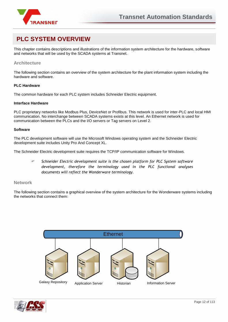
The following section contains a graphical overview of the system architecture for the Wonderware systems including the networks that connect them:
Ethernet
Galaxy Repository Application Server Historian Information Server
Transnet Automation Standards
Page 13 of 113
Users
The primary users of the PLC system will be the Transnet technical personnel:
1) Process Engineers.
2) Control & Instrumentation or Software Engineers.
3) Maintenance Engineers & Instrument Technicians.
Environment
Each PLC system will be installed in a controlled environment in accordance with the specifications of the hardware
equipment manufacturer. The PLC’s and will be housed in a Transnet approved electrical panel and should adhere to
all Transnet specifications.
Software Structure
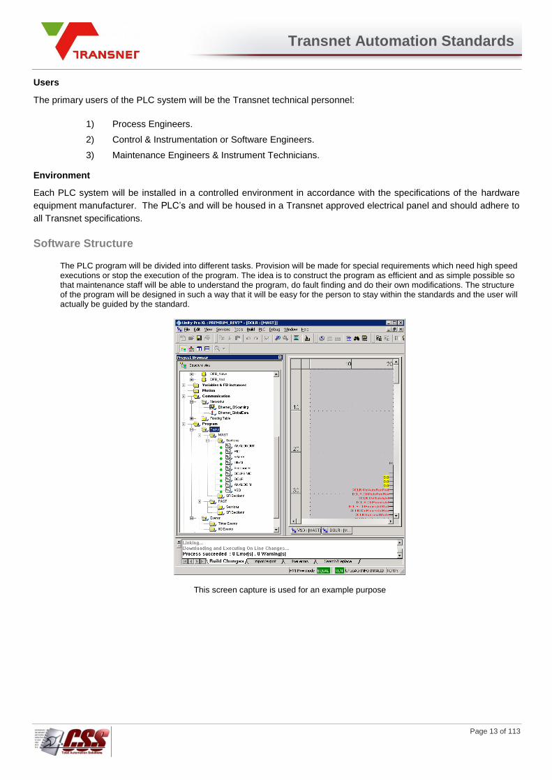
The PLC program will be divided into different tasks. Provision will be made for special requirements which need high speed executions or stop the execution of the program. The idea is to construct the program as efficient and as simple possible so that maintenance staff will be able to understand the program, do fault finding and do their own modifications. The structure of the program will be designed in such a way that it will be easy for the person to stay within the standards and the user will actually be guided by the standard.
This screen capture is used for an example purpose

Transnet Automation Standards
Page 14 of 113
Tasks Mask: Main Task
The master task represents the main task of the application program. It is made up of sections and subroutines. The preferred language used is FBD. The majority of the program will be written in the master task division. To execute the plc program more efficiently, the FDB code is created in a Derived Function Block in order for reusability. Task under this division:
Analog Input/Output blocks.
Unit/Group actions
Digital Input/Output Blocks
Standard PID controllers
Motor blocks
Valve Control
Totalizers
Counters
Revision control
Fast: Fast Task
The period of fast Task is short (in the range of 1 to 255 ms) and the priority is higher than the Master Task. The use of Fast Task will be limited and set as short possible to avoid overflow of lower-priority tasks.
EV or timer: Event Tasks
An event will be used to interrupt the program due to specific condition or event. Event programming will be written in FDB. It normally comes from Input/output modules while timer events come from timers. Events include:
Emergency stops
Hard Wire interlocks
Events that could result in loss of life or damage to equipment

Transnet Automation Standards
Page 15 of 113
Master Template Library
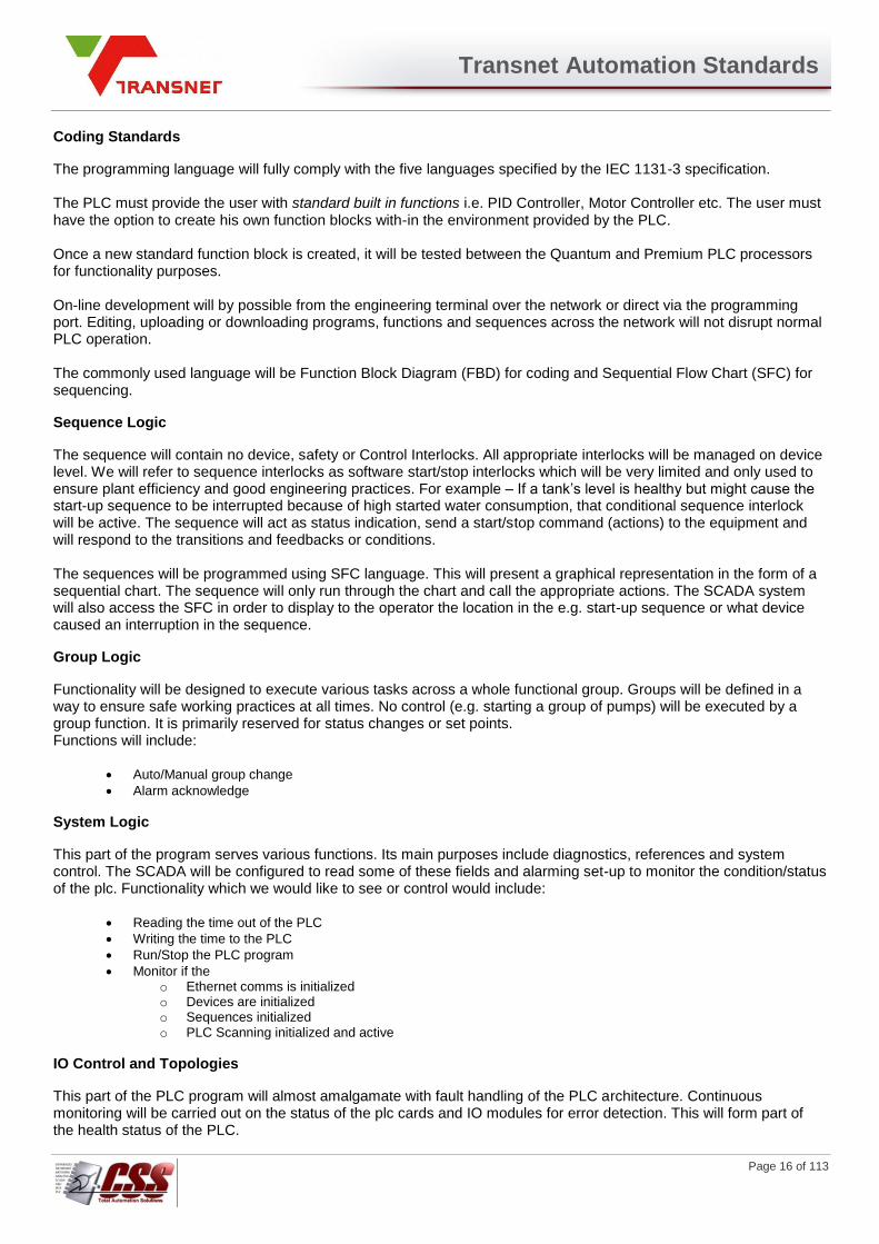
All the created EF’s (Elementary functions), EFB’s (Elementary function blocks), DFB’s (Derived function blocks) and DDT’s (Derived Data Types) will be developed and placed in a library set. Only one code need to be developed and maintained for function blocks. These created function blocks will be thoroughly developed and tested. Thus errors are eliminated; problem solving is made easy, additional programming is simplified and engineering cost minimized. The tested and accepted block will then be placed in the family library and utilized all over the program - ensuring standardization. By placing the function blocks or code in the library, it can be reused and easily managed. Not all PLC programs are the same or offer the same functionality but as far as possible the created instances must be placed in a global library.
This screen capture is used for an example purpose
Transnet Automation Standards
Page 16 of 113
Coding Standards
The programming language will fully comply with the five languages specified by the IEC 1131-3 specification. The PLC must provide the user with standard built in functions i.e. PID Controller, Motor Controller etc. The user must have the option to create his own function blocks with-in the environment provided by the PLC. Once a new standard function block is created, it will be tested between the Quantum and Premium PLC processors for functionality purposes. On-line development will by possible from the engineering terminal over the network or direct via the programming port. Editing, uploading or downloading programs, functions and sequences across the network will not disrupt normal PLC operation. The commonly used language will be Function Block Diagram (FBD) for coding and Sequential Flow Chart (SFC) for sequencing.
Sequence Logic
The sequence will contain no device, safety or Control Interlocks. All appropriate interlocks will be managed on device level. We will refer to sequence interlocks as software start/stop interlocks which will be very limited and only used to ensure plant efficiency and good engineering practices. For example – If a tank’s level is healthy but might cause the start-up sequence to be interrupted because of high started water consumption, that conditional sequence interlock will be active. The sequence will act as status indication, send a start/stop command (actions) to the equipment and will respond to the transitions and feedbacks or conditions. The sequences will be programmed using SFC language. This will present a graphical representation in the form of a sequential chart. The sequence will only run through the chart and call the appropriate actions. The SCADA system will also access the SFC in order to display to the operator the location in the e.g. start-up sequence or what device caused an interruption in the sequence.
Group Logic
Functionality will be designed to execute various tasks across a whole functional group. Groups will be defined in a way to ensure safe working practices at all times. No control (e.g. starting a group of pumps) will be executed by a group function. It is primarily reserved for status changes or set points. Functions will include:
Auto/Manual group change
Alarm acknowledge
System Logic
This part of the program serves various functions. Its main purposes include diagnostics, references and system control. The SCADA will be configured to read some of these fields and alarming set-up to monitor the condition/status of the plc. Functionality which we would like to see or control would include:
Reading the time out of the PLC
Writing the time to the PLC
Run/Stop the PLC program
Monitor if the o Ethernet comms is initialized o Devices are initialized o Sequences initialized o PLC Scanning initialized and active
IO Control and Topologies
This part of the PLC program will almost amalgamate with fault handling of the PLC architecture. Continuous monitoring will be carried out on the status of the plc cards and IO modules for error detection. This will form part of the health status of the PLC.

Transnet Automation Standards
Page 17 of 113
Watchdog Procedure
The watchdog timer is for communication detection between devices. The action associated with the watchdog will be based on the functionality of the circuit and safety aspects of the operation. Basic rule – If the device is used in safety circuit or loosing the device could result in an immediate unsafe condition, for example loosing the flow switches on the furnace cooling circuit, the watchdog will trip the furnace or controlled equipment. If the watchdog timer is activated on
the device used only for monitoring or which does not result in a dangerous or unsafe condition, the watchdog will trigger a communication alarm.
General Watchdog Practice
A watchdog timer will be setup for each device. That includes all IO Scanning devices and PLC’s for Global Data inter-PLC communication.
Every watchdog will comprise of a (1) heartbeat - device activity detection pulse, and a communication (2) health bit (internal PLC function).
Actual watchdog pulse (combination of heartbeat and health bit) will be connected to the RAW input of a digital input block.
Output of digital input watchdog block will be used in the rest of the PLC program for control purposes.
DI object will be placed on network topology page, on top of the associated device.
Alarming will be assigned according to the priority of the alarms. All watchdog failures should be treated as status 900 alarms.
A “Watchdog” section will be created in each PLC program. All watchdogs/ watchdog detection code will be compiled in this block. From this section, the watchdog bits will be connected to the DI inputs.
The watchdog action/alarm will be determined by the detection time of a health or heartbeat bits. The delay time of both these bits will thus be the same.
Watchdog alarm/trip condition delay time period determined by device failure time. See Watch dog implementation section.
Naming Convention of Watchdogs
The naming convention of watchdogs will follow the guidelines of the tag name structure as described in the Engineering Standards. Because the pulses or variables are not physical IO, the last part of the tag name will be a descriptive field. As mentioned, the watchdog will be connected to the input of a DI block. Thus, 3 variable combinations will be created: WatchdogVariable_I, WatchdogVariable, WatchdogVariable_HMI.
Identification of Devices
Device will be allocated sequential numbers according to the amount of devices in the panel. The number will not be referenced to the type of device. Example – As indicated, the ABB transducer can be identified as device number 1. The description of the tag will specify the details of the device.
IO Scanning
(See Screen Capture IOScan3)
PLC
01
02
03
10_F4_FC01_PA01
ABB
EGX
Anybus
Transnet Automation Standards
Page 18 of 113
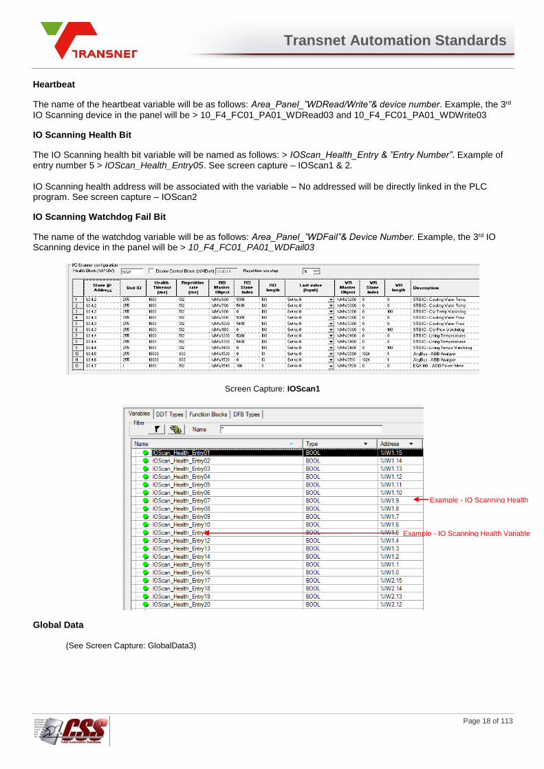
Heartbeat
The name of the heartbeat variable will be as follows: Area_Panel_”WDRead/Write”& device number. Example, the 3rd IO Scanning device in the panel will be > 10_F4_FC01_PA01_WDRead03 and 10_F4_FC01_PA01_WDWrite03
IO Scanning Health Bit
The IO Scanning health bit variable will be named as follows: > IOScan_Health_Entry & ”Entry Number”. Example of entry number 5 > IOScan_Health_Entry05. See screen capture – IOScan1 & 2. IO Scanning health address will be associated with the variable – No addressed will be directly linked in the PLC program. See screen capture – IOScan2
IO Scanning Watchdog Fail Bit
The name of the watchdog variable will be as follows: Area_Panel_”WDFail”& Device Number. Example, the 3rd IO Scanning device in the panel will be > 10_F4_FC01_PA01_WDFail03
Screen Capture: IOScan1
Global Data
(See Screen Capture: GlobalData3)
Example - IO Scanning Health Bit Address
Example - IO Scanning Health Variable

Transnet Automation Standards
Page 19 of 113
Heartbeat
The name of the heartbeat pulse will be as follows: PLC Name_Panel_WDPulse & Device Number. Example, Inter-PLC communication between FCE4 and FCE3 Batch Plant PLC’s: 10_F3_BP00_PA01_WDPulse01
Global Data Health Bit
The Global Data health bit variable will be named as follows: Global_DATA_Health_PLCName. Example, Inter-PLC communication between FCE4 and FCE3 Batch Plant PLC’s: Global_DATA_Health_10_F3_BP00.
Global Data Watchdog Fail Bit The name of the watchdog variable will be as follows: PLCName_Panel_”WDFail”& Device Number. Example, Inter-PLC communication between FCE4 and FCE3 Batch Plant PLC’s: 10_F3_BP00_PA01_WDFail01
Philosophy
If communication is lost between devices (IO Scanning) or PLC’s (Global Data), a certain course of action must be taken based on the PLC’s function, safety risk and statuses. The PLC’s action will be described in relation to specific communication failures. Note: In all cases, the Functional Description document must be considered as safety complications might be identified during the HAZOP study. If changes to the standard are required, it will first be communicated and verified by Transnet before implementation.
Transnet Automation Standards
Page 20 of 113
ARCHESTRA DATABASE CONFIGURATION
The ArchestrA Database chapter includes conventions used for the data capture and the processing of the variables within the database, including Input/Output (I/O) and Memory tag naming conventions, application graphic screens and file naming conventions.
Tag Naming Convention
A tag is a variable with a unique identifier used to represent a device object in the ArchestrA Galaxy with its associated values to an I/O source (i.e. a physical input or output state) or a memory-derived variable (i.e. internal calculation or system variable). The ArchestrA software will permit the system developer to design an application capable of monitoring, responding and transmitting data to specific objects within the Device Integration Object (DIObject) Name. The DIObject is the ArchestrA object that communicates with the PLC. The following sections contain descriptions for the tag naming convention for both I/O (external) and memory tags used with ArchestrA and InTouch.
Area / Plant
The areas in ArchestrA will be named using the full logical name or a descriptive abbreviation thereof. The actual area name to be used will be defined in the area’s own functional specification as used by the MES system. The plant names used in the model will be a self-explanatory acronym for that plant area and will always be unique and contain three alphanumeric characters. For example:
MIL = Millennium Tower
CFI = CFI & Bubble Screen
FYN = Fynnlands Substation
PI2 = Pier 2 Substation
DHI = DHI Substation
STA = Stanger Street Substation
AD33 = Allan Dalton 33kV Substation
OTB = OTB Aircon
1900 = Tony's Office (NDM Control Monitoring only)
ENG = Development Office
PI1 = Pier 1 Fire Station
IVF = Island View Fire Officer
CFO = Chief Fire Officer
Transnet Automation Standards
Page 21 of 113
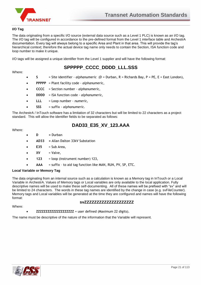
I/O Tag
The data originating from a specific I/O source (external data source such as a Level 1 PLC) is known as an I/O tag. The I/O tag will be configured in accordance to the pre-defined format from the Level 1 interface table and ArchestrA documentation. Every tag will always belong to a specific Area and Plant in that area. This will provide the tag’s hierarchical context; therefore the actual device tag name only needs to contain the Section, ISA function code and loop number to make it unique. I/O tags will be assigned a unique identifier from the Level 1 supplier and will have the following format:
SPPPPP_CCCC_DDDD_LLL.SSS Where:
S = Site identifier - alphanumeric (D = Durban, R = Richards Bay, P = PE, E = East London),
PPPPP = Plant facility code - alphanumeric,
CCCC = Section number - alphanumeric,
DDDD = ISA function code - alphanumeric,
LLL = Loop number - numeric,
SSS = suffix - alphanumeric.
The ArchestrA / InTouch software has a limitation of 32 characters but will be limited to 22 characters as a project standard. This will allow the identifier fields to be separated as follows:
DAD33_E35_XV_123.AAA
Where:
D = Durban
AD33 = Allan Dalton 33kV Substation
E35 = Sub Area,
XV = Valve,
123 = loop (instrument number) 123,
AAA = suffix – to aid tag function like MAN, RUN, PV, SP, ETC.
Local Variable or Memory Tag The data originating from an internal source such as a calculation is known as a Memory tag in InTouch or a Local Variable in ArchestrA. Values of Memory tags or Local variables are only available to the local application. Fully descriptive names will be used to make these self-documenting. All of these names will be prefixed with “sv” and will be limited to 24 characters. The words in these tag names are identified by the change in case (e.g. svFileCounter). Memory tags and Local variables will be generated at the time they are configured and names will have the following format:
svZZZZZZZZZZZZZZZZZZZZ Where:
ZZZZZZZZZZZZZZZZZZZZ = user defined (Maximum 22 digits).
The name must be descriptive of the nature of the information that the Variable will represent.

Transnet Automation Standards
Page 22 of 113
Device Integration (D/I) Object Naming
To acquire a data value from another source via Input/Output (I/O), ArchestrA must have certain information about the data source. This information is specified in the Device Integration (D/I) object name definition and includes the name of the Scan Group, which contains the data value. A D/I Object must be defined for every I/O source (PLC) that data is acquired from. D/I Object definitions will be named as follows:
S_PPPPP_XX
Where: S = Area abbreviation. The area abbreviations are as follows:
Code Area
M Millennium Tower
C Compressor House
E Engineering
Table 0-1: Area Identification Codes
PPPPP = Up to five letters describing the source type logically. For example:
MIL for Millennium Tower PLC’s,
SUB for Substation PLC’s,
XLS for Excel data,
MES (for MES data), etc.
XX = Source number. Number representing a particular Source within the area (typically the PLC
number). This number is defined in the SCADA Functional Analysis applicable to each area.
One or more Scan Groups must be defined for every D/I Object. Scan Groups will be named as follows:
Z000
Where:
Z = I/O Access type as follows:
A for an Analogue I/O Source,
D for a Digital I/O Source,
S for a String (ASCII) I/O Source,
G for a Generic Source.
000 = Sequential source number starting at 001
Different Scan Groups can be specified for the different types of data because the data can be scanned at different rates. A typical set-up for an area with one PLC, the D/I Object and Scan Group definitions would be as follows:
Source Description D/I Object name Scan Group Name
Excel Analogue Data M_XLS_Y1 A001
MES Analogue Data T_MES_01 A001
MES String Data T_MES_01 S001
Table 0-2: D/I Object and Scan Group Configuration Example
Transnet Automation Standards
Page 23 of 113
HUMAN MACHINE INTERFACE CONFIGURATION
A Human Machine Interface (HMI) is a graphical computer based interface that provides the operator with a consistent format for process representation, monitoring and control. The following chapter provides guidelines for the general design of the operator interface.
Design Standard
The graphic system will be self-explanatory with clearly written English language messages indicating the available options within the specific graphic screen to the operator. Graphic screens will be simple, easy to understand and will include only necessary information. All graphic objects will be represented in a simple 2-dimensional fashion, similar to the P&ID representation. They will be designed to minimise operation errors, and will always be clear and evident. Mimic diagrams and graphic symbols will be designed in accordance with:
1. ISA-5.1-1984 Instrumentation symbols and identification and
2. ISA-5.5-1985 Graphic Symbols for Process Displays
Graphic screens will be configured using one or more of the following configurations:
1. Plant overview to assist the operator with an overall understanding of the areas of the plant that are to
be controlled,
2. Simplified block diagram to illustrate sequences, interactions and selected options,
3. Diagrammatic representation of the process equipment using predetermined symbols to represent the
various equipment,
4. Process and Instrumentation Diagram (P&ID) using recognised instrumentation and electrical symbols.
On-screen mimic documentation will include descriptions and identification tags in accordance with the P&ID diagrams.The units of measurement used in the mimic images will be indicated in direct reading "SI" units of measurement with their multiples and sub-multiples.
Window Format
The HMI process will be supervised at the basic device level in the mimic images during operation. Control will be possible from the mimic views. Screen objects will be organised along various guidelines as follows (See Figure 0-1: Application Graphic Screen Layout).
1. A Banner window will occupy areas 1 and 2 and will always be visible.
2. Each application graphic screen or view will occupy areas 3 and 4,
3. Sub-windows will be displayed as pop-up screens over the application graphic screen (area 3 and 4).
4. Recipes and control functions will occupy area 4 when required.
Sub-windows (pop-up screens) will be used to supplement full size screens by offering the operator quick access to related information or commands without having to exit the application screen. Example of sub-window application: A PID controller representing the device to be controlled will be displayed on a monitor screen whenever a user needs to transmit a set point (remote setting or remote control). The user (Maintenance personnel) will be able to access all parameters for the specific device by selecting the PID controller tune action button with the pointing device. The sub-window will display all of the selected controller parameter details whenever an inlaid window is to be displayed. The user will obtain all data associated with the device and will be able to issue commands (subject to user application privilege) within specific areas of the sub-window. The sub-window will dynamically be updated upon reception of data from the database.
Transnet Automation Standards
Page 24 of 113
Window Configuration and Size The HMI’s graphic display must be configured to display 1920×1080p with 32-bit colour or greater, with a horizontal frequency of 85 Hz.
Customised Screen Format
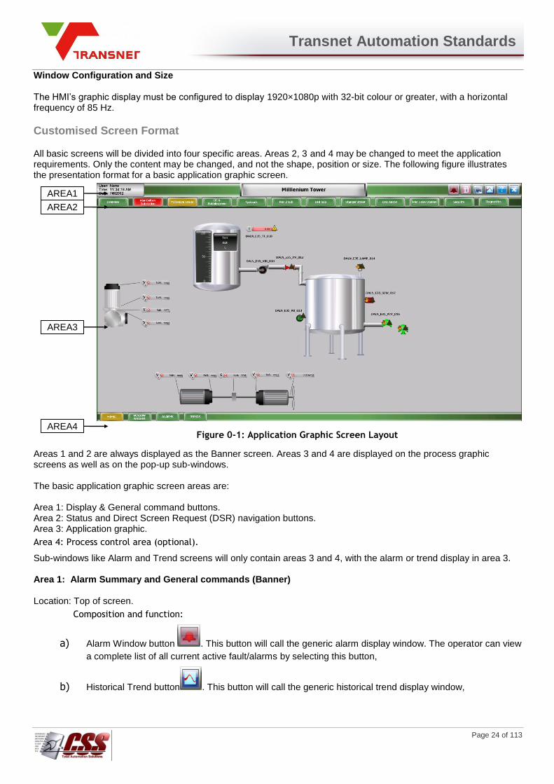
All basic screens will be divided into four specific areas. Areas 2, 3 and 4 may be changed to meet the application requirements. Only the content may be changed, and not the shape, position or size. The following figure illustrates the presentation format for a basic application graphic screen.
Figure 0-1: Application Graphic Screen Layout
Areas 1 and 2 are always displayed as the Banner screen. Areas 3 and 4 are displayed on the process graphic screens as well as on the pop-up sub-windows. The basic application graphic screen areas are: Area 1: Display & General command buttons. Area 2: Status and Direct Screen Request (DSR) navigation buttons. Area 3: Application graphic.
Area 4: Process control area (optional).
Sub-windows like Alarm and Trend screens will only contain areas 3 and 4, with the alarm or trend display in area 3. Area 1: Alarm Summary and General commands (Banner) Location: Top of screen.
Composition and function:
a) Alarm Window button . This button will call the generic alarm display window. The operator can view
a complete list of all current active fault/alarms by selecting this button,
b) Historical Trend button . This button will call the generic historical trend display window,
AREA1
AREA2
AREA3
AREA4
Transnet Automation Standards
Page 25 of 113
c) Security button . This button will display the log-on pop-up screen, OR if a user is logged on the
security button will look like and clicking on it will log off the current user
d) Operator, Time and Date display area . Operator: This field is linked to the
$Operator string variable. Time (HH:MM:SS). This field is dynamically linked to the $Timestring system
variable. Date (MM/DD/YYYY). This field is dynamically linked to the $Datestring system variable.
e) Site name area This will display the name of the
site currently being displayed in Area 3 and Area 4.
This area will always be visible. Area 2: Navigation Area Location: Immediately under Area 1.
Composition and function:
1. Used to illustrate the overall plant facility fault/alarm and operation status and will be used to access
other process graphic screens.
2. The operator may select the navigation buttons to access other process screens. The available
information from these graphic screens are:
Fault/alarm status related to the particular graphic screen and/or functional section,
This area will always be visible.
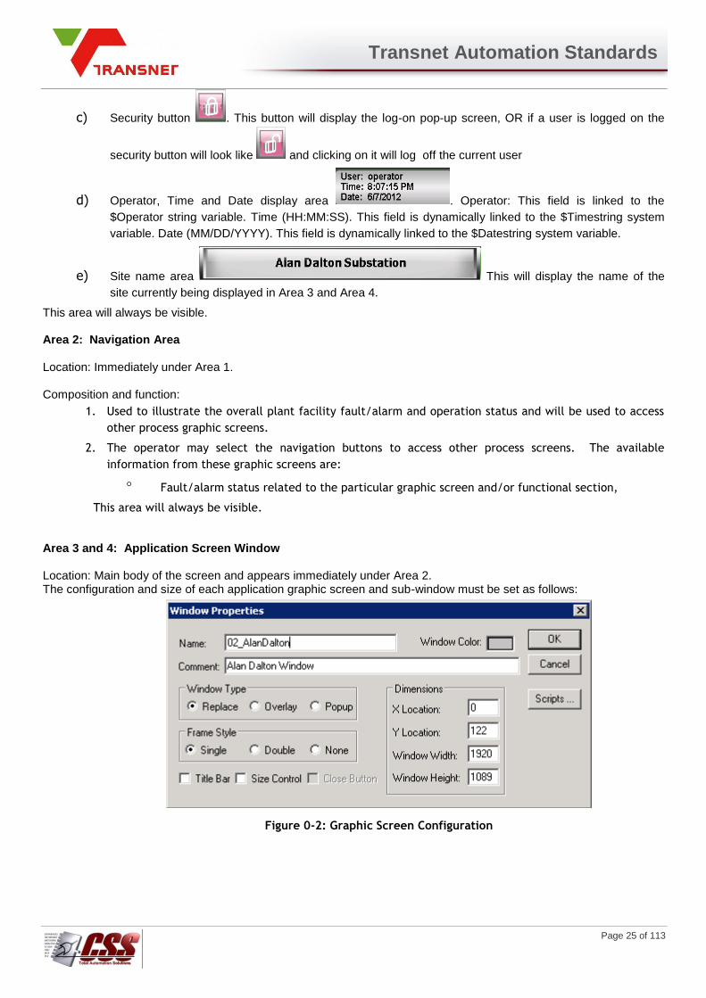
Area 3 and 4: Application Screen Window Location: Main body of the screen and appears immediately under Area 2. The configuration and size of each application graphic screen and sub-window must be set as follows:
Figure 0-2: Graphic Screen Configuration
Transnet Automation Standards
Page 26 of 113
. Area 3: Composition and function:
1. This is a window fitting over area 3 or areas 3 and 4 (area of the screen representing the monitored
process).
2. The application's main menu or overview screen will contain a paging object for this screen. The screen
name and functional description of the screen will be displayed at the top of area 3.
3. An application graphic area may include menus and sub-menus, detailed views of the application, trend
views, graphs and any other graphics appropriate to represent the monitored process.
4. The area may contain symbols for control devices (seq. start / seq. stop of functional sections will
always be located in the top left section of this area), graphs, blocks of text, and other graphic objects.
The operator may move the cursor from object to object within the area and display multiple dynamic
sub-windows that are displayed on the graphic screen.
5. Sub-windows will be able to contain any data and command options that would appear on a full size
application graphic screen (except an application alarm window).
The Close button gets replaced by a Quit button on the overview screen and is only visible when logged on as administrator. This button will stop WindowViewer to exit to the operating system. Area 4: Context sensitive control area (optional) Location: Bottom part of the screen. Composition and function: This area will be used to display buttons that will navigate to process/alarm/trending screens that are related to the site selected from the main navigation area.
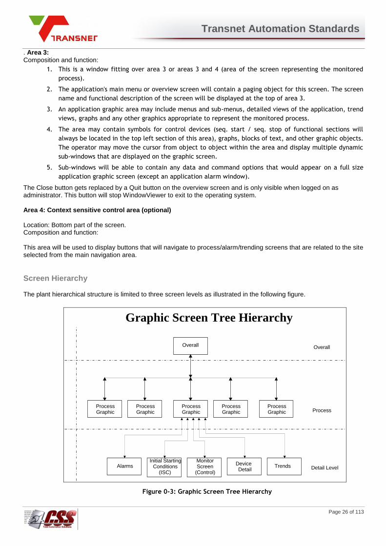
Screen Hierarchy
The plant hierarchical structure is limited to three screen levels as illustrated in the following figure.
Overall View
Process Graphic
Process Graphic
Process Graphic
Process Graphic
Process Graphic
Alarms Initial Starting
Conditions (ISC)
Monitor Screen
(Control) Device Detail
Graphic Screen Tree Hierarchy
Overall Level
Process Level
Detail Level Trends
Figure 0-3: Graphic Screen Tree Hierarchy
Transnet Automation Standards
Page 27 of 113
1. Overall level: Banner, Navigation area and process overview.
This screen will be configured as the "Power Up" default screen. This screen will be
accessible at all times by selecting the Overview button.
2. Process level: Main Process mimics.
3. Detail level (pop-up screens):
a. Detailed equipment mimics (zoom).
b. Initial Starting Conditions (if applicable).
c. Monitor Control Screens (if applicable).
d. Alarm display.
e. Alarm Histories: list of previous and active alarms.
f. Trend displays.
g. Device Detail pop-up screens.
The user may access any of the sub-level screens from the control buttons or the process overview screens, with the navigation buttons in Area 2. The user will be able to navigate to the main menu screen or detail level screens from the sub-level screen. The operator may also access other process level screens. Overall and process level screens will be accessible from all other level screens. Navigation from a detail level screen will be defined in the functional analysis of the specific area.Mimics will be structured to achieve a uniform, consistent feel to the operation throughout the plant. It will be possible to navigate from screen to screen by selecting objects that have been defined to display the next logical application graphic screen or sub-window.
Overall
Transnet Automation Standards
Page 28 of 113
Screen Selection
Screen objects may be selected to:
1. Display a new application graphic screen,
2. Open or close a sub-window,
The displayed screen objects are identified as Paging Types within the InTouch package. The objects will be used to navigate from one screen window to another screen window. Paging types may be attached to control buttons, individual buttons, or any other screen object of the mimic. The following sections contain descriptions for the paging screen objects used to navigate between the various screen application graphics and sub-windows. Window and Sub-window Selection Paging buttons will be provided to navigate between screens and allow the user to activate functions. A new screen will be displayed when a button is selected. There are two types of buttons:
1. Function Buttons used to open a sub-window,
2. Navigation buttons used to launch a new application graphic screen.
The following table contains definitions for Function buttons.
Label Operation
Alarms Displays detail Alarm information.
Network Displays detail level network status screen.
Trend Displays a real-time trend window.
Help Displays a Help context sensitive screen
Print Print a hard copy of the current view
Close Closes the sub-window.
Table 0-1: Function Buttons
The standard Function button symbol will be as follows:
Navigation shall be achieved by selecting the paging object with the pointing device (mouse).
Graphic Screen Naming Convention
Graphic screens must be named using a number followed by a short descriptive name For example, the Millennium Tower screen will be named:
03_MilleniumTower Sequential numbers are used for screens covering different sites. Screens with that have content specific to a particular site will have the number prefix of that particular site. E.g. the InTouch screens related to the Millenium Tower all start with “03_”.
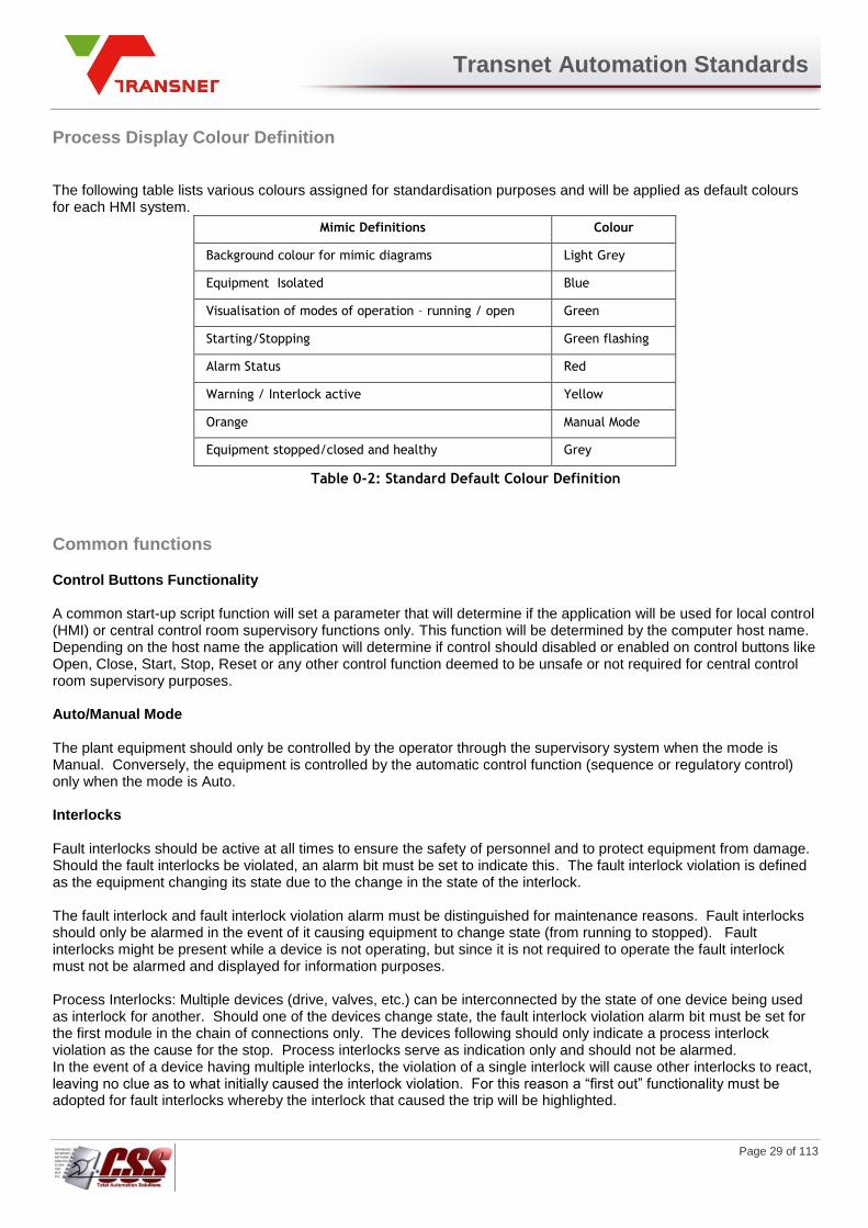
Transnet Automation Standards
Page 29 of 113
Process Display Colour Definition
The following table lists various colours assigned for standardisation purposes and will be applied as default colours for each HMI system.
Mimic Definitions Colour
Background colour for mimic diagrams Light Grey
Equipment Isolated Blue
Visualisation of modes of operation – running / open Green
Starting/Stopping Green flashing
Alarm Status Red
Warning / Interlock active Yellow
Orange Manual Mode
Equipment stopped/closed and healthy Grey
Table 0-2: Standard Default Colour Definition
Common functions
Control Buttons Functionality A common start-up script function will set a parameter that will determine if the application will be used for local control (HMI) or central control room supervisory functions only. This function will be determined by the computer host name. Depending on the host name the application will determine if control should disabled or enabled on control buttons like Open, Close, Start, Stop, Reset or any other control function deemed to be unsafe or not required for central control room supervisory purposes. Auto/Manual Mode The plant equipment should only be controlled by the operator through the supervisory system when the mode is Manual. Conversely, the equipment is controlled by the automatic control function (sequence or regulatory control) only when the mode is Auto. Interlocks Fault interlocks should be active at all times to ensure the safety of personnel and to protect equipment from damage. Should the fault interlocks be violated, an alarm bit must be set to indicate this. The fault interlock violation is defined as the equipment changing its state due to the change in the state of the interlock. The fault interlock and fault interlock violation alarm must be distinguished for maintenance reasons. Fault interlocks should only be alarmed in the event of it causing equipment to change state (from running to stopped). Fault interlocks might be present while a device is not operating, but since it is not required to operate the fault interlock must not be alarmed and displayed for information purposes. Process Interlocks: Multiple devices (drive, valves, etc.) can be interconnected by the state of one device being used as interlock for another. Should one of the devices change state, the fault interlock violation alarm bit must be set for the first module in the chain of connections only. The devices following should only indicate a process interlock violation as the cause for the stop. Process interlocks serve as indication only and should not be alarmed. In the event of a device having multiple interlocks, the violation of a single interlock will cause other interlocks to react, leaving no clue as to what initially caused the interlock violation. For this reason a “first out” functionality must be adopted for fault interlocks whereby the interlock that caused the trip will be highlighted.
Transnet Automation Standards
Page 30 of 113
Standard Graphics Symbols
APPENDIX A [A1], HMI Symbols for Process Display will contain example symbol definitions that are to be used with the application graphic screens. The actual symbol shape should represent the symbol used on the relevant P&ID and ISA Standards. The definition and properties of each symbol will reference the associated object template in ArchestrA. For example, a Valve symbol’s properties in InTouch will reference the properties of the $Valve template in ArchestrA. See Section 0

Transnet Automation Standards
Page 31 of 113
Device Templates, for a full device and symbol definition.
Process Display
The main function of the HMI system is the process display. The objective is to group information required by the plant facility users, into mimic images for the optimal plant facility operation. Once displayed, the mimic images will be updated dynamically from the Application Server. The mimic images will be composed of two parts:
1. Background: static objects,
2. Animation: dynamic objects.
An object's display type will determine the object's appearance at run-time. By selecting the appropriate display type and assigning the appropriate point, it will be possible to have an object change colour or appear to change shape or position, in response to the status of a device or process. Static Objects Static objects are defined as objects that do not change in response to input data (i.e.; the object will retain the same shape and colour during run-time). Alphanumeric Data Icon identification descriptors are alphanumeric static fields used for equipment identification. Icon identification descriptors will be black on a grey background and will be positioned below the process icon. The text font and size must be Arial 8. Icon identification descriptors will be as illustrated with the pump symbol. Dynamic Objects A dynamic object is defined as an object associated to a specific data source that change along pre-defined guidelines as the input data is changed. Once the images have been created, their animation will be defined by the database variables. The following guidelines will be in place:
1. Explicit display of a variable value with alphanumeric characters like PV (Process variable) and SP
(Setpoint). The following figure illustrates a PV value display symbol.
.
Figure 0-4: PV Digital Display Symbol
2. Display type objects:
- bar graphs,
- modifying the colour of a symbol,
- modifying shape and position of a screen object.
Dynamic objects may also have static portions like the Icon identification descriptor and Engineering units. Dynamic Data Dynamic display fields will be used to present the operator with an indication of the specific status and fault/alarm relating to the represented equipment. Status Labels The following table lists the standard status labels that will be used to define equipment or functional section mode.
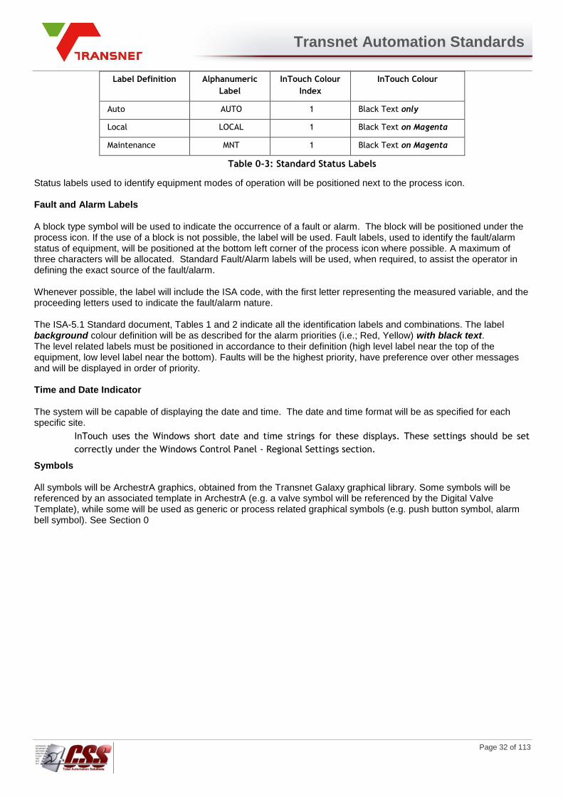
Transnet Automation Standards
Page 32 of 113
Label Definition Alphanumeric
Label
InTouch Colour
Index
InTouch Colour
Auto AUTO 1 Black Text only
Local LOCAL 1 Black Text on Magenta
Maintenance MNT 1 Black Text on Magenta
Table 0-3: Standard Status Labels
Status labels used to identify equipment modes of operation will be positioned next to the process icon. Fault and Alarm Labels A block type symbol will be used to indicate the occurrence of a fault or alarm. The block will be positioned under the process icon. If the use of a block is not possible, the label will be used. Fault labels, used to identify the fault/alarm status of equipment, will be positioned at the bottom left corner of the process icon where possible. A maximum of three characters will be allocated. Standard Fault/Alarm labels will be used, when required, to assist the operator in defining the exact source of the fault/alarm. Whenever possible, the label will include the ISA code, with the first letter representing the measured variable, and the proceeding letters used to indicate the fault/alarm nature. The ISA-5.1 Standard document, Tables 1 and 2 indicate all the identification labels and combinations. The label background colour definition will be as described for the alarm priorities (i.e.; Red, Yellow) with black text. The level related labels must be positioned in accordance to their definition (high level label near the top of the equipment, low level label near the bottom). Faults will be the highest priority, have preference over other messages and will be displayed in order of priority. Time and Date Indicator The system will be capable of displaying the date and time. The date and time format will be as specified for each specific site.
InTouch uses the Windows short date and time strings for these displays. These settings should be set
correctly under the Windows Control Panel - Regional Settings section.
Symbols All symbols will be ArchestrA graphics, obtained from the Transnet Galaxy graphical library. Some symbols will be referenced by an associated template in ArchestrA (e.g. a valve symbol will be referenced by the Digital Valve Template), while some will be used as generic or process related graphical symbols (e.g. push button symbol, alarm bell symbol). See Section 0
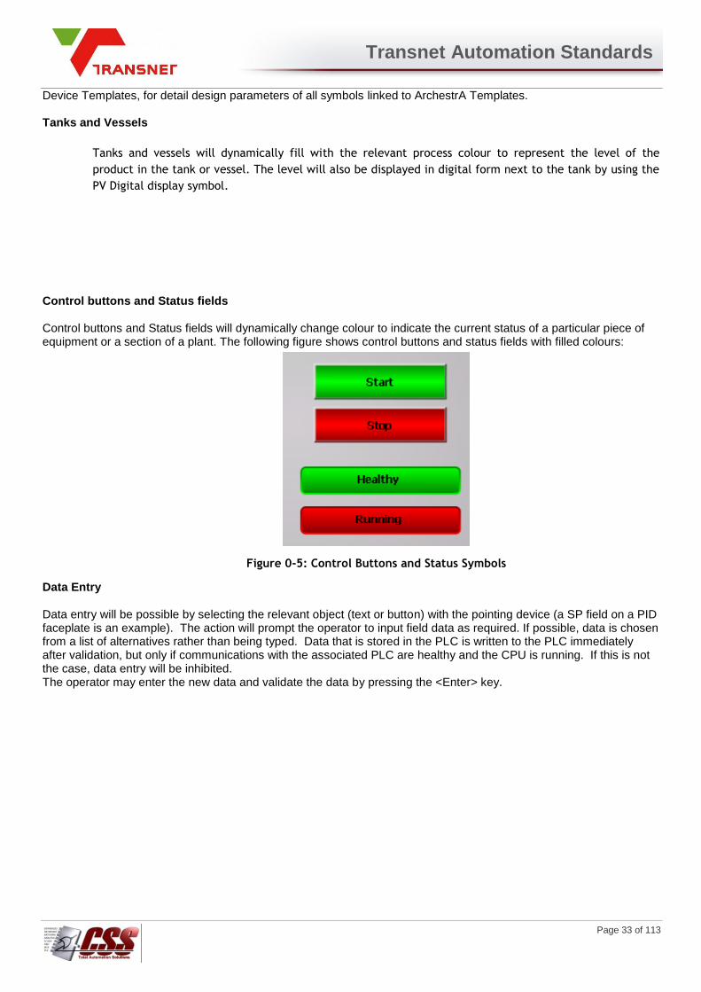
Transnet Automation Standards
Page 33 of 113
Device Templates, for detail design parameters of all symbols linked to ArchestrA Templates.
Tanks and Vessels
Tanks and vessels will dynamically fill with the relevant process colour to represent the level of the
product in the tank or vessel. The level will also be displayed in digital form next to the tank by using the
PV Digital display symbol.
Control buttons and Status fields Control buttons and Status fields will dynamically change colour to indicate the current status of a particular piece of equipment or a section of a plant. The following figure shows control buttons and status fields with filled colours:
Figure 0-5: Control Buttons and Status Symbols
Data Entry Data entry will be possible by selecting the relevant object (text or button) with the pointing device (a SP field on a PID faceplate is an example). The action will prompt the operator to input field data as required. If possible, data is chosen from a list of alternatives rather than being typed. Data that is stored in the PLC is written to the PLC immediately after validation, but only if communications with the associated PLC are healthy and the CPU is running. If this is not the case, data entry will be inhibited. The operator may enter the new data and validate the data by pressing the <Enter> key.
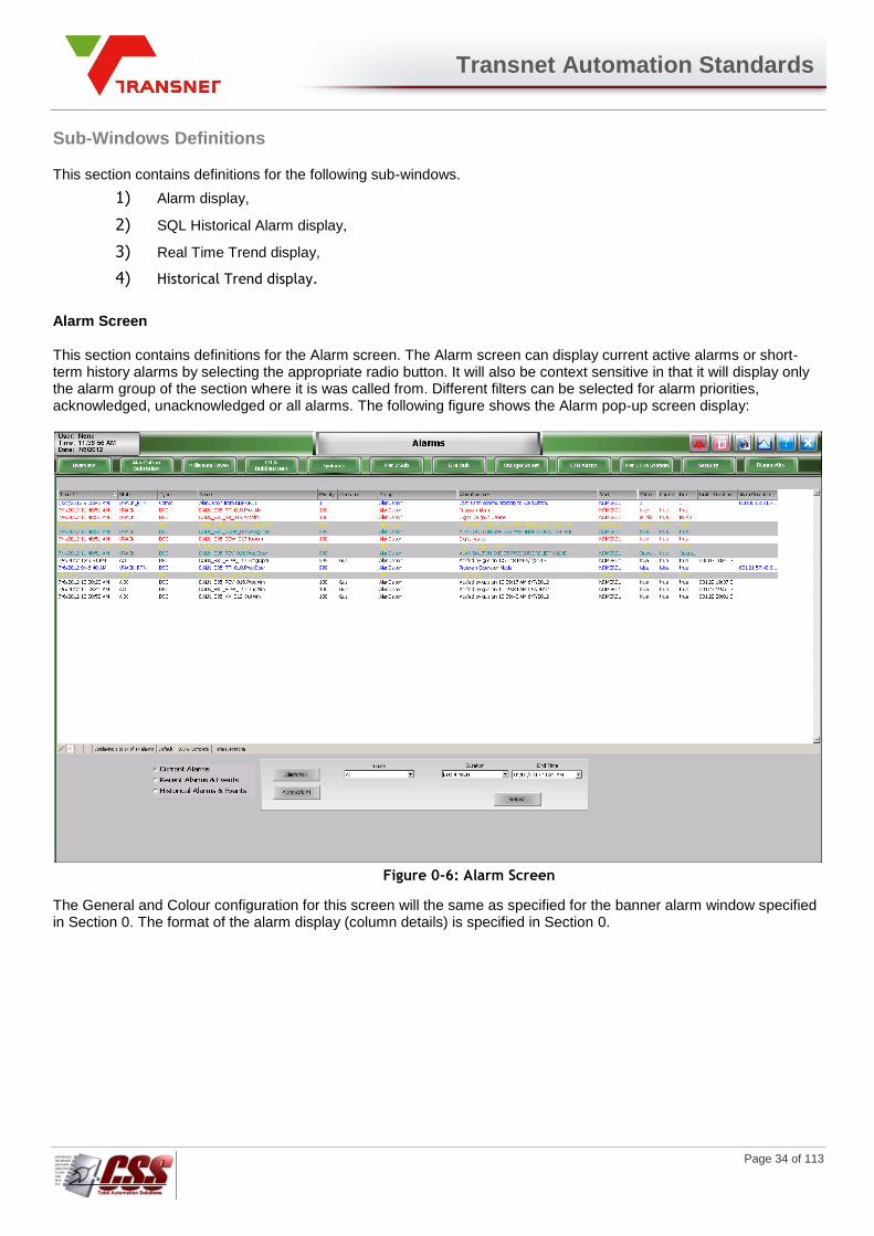
Transnet Automation Standards
Page 34 of 113
Sub-Windows Definitions
This section contains definitions for the following sub-windows.
1) Alarm display,
2) SQL Historical Alarm display,
3) Real Time Trend display,
4) Historical Trend display.
Alarm Screen This section contains definitions for the Alarm screen. The Alarm screen can display current active alarms or short-term history alarms by selecting the appropriate radio button. It will also be context sensitive in that it will display only the alarm group of the section where it is was called from. Different filters can be selected for alarm priorities, acknowledged, unacknowledged or all alarms. The following figure shows the Alarm pop-up screen display:
Figure 0-6: Alarm Screen
The General and Colour configuration for this screen will the same as specified for the banner alarm window specified in Section 0. The format of the alarm display (column details) is specified in Section 0.

Transnet Automation Standards
Page 35 of 113
SQL Historical Alarms Selecting the option “Historical Alarms & Events” the Alarm View will display longer term historical alarms stored in the alarm MSSQL database on the Historian server. The display can be manipulated by setting up filters or by selecting pre-set saved filters. Filters should be configured for every alarm area. The following figure shows the SQL Alarm page:
Figure 0-7: SQL Alarm Screen
Real Time Trends The Real-time trend function will be used to allow the user to graph recent data from a maximum of four points (variable) on a single view. Real-time trends will be built as defined in the specific Functional Analysis of each area or plant. These trends are application specific and can be displayed on any screen as required, either by selecting an object on the process screen or by selecting the RT Trend button in the navigation area. The system will be defined ensuring that Run-time operators will not be able to modify Real-time trends configuration. Any configuration change may only be performed by maintenance level authorised personnel (sampling rate, point selection, etc.). Historical Trend Screen See section 0 for details on the Historical Trend screen.
Transnet Automation Standards
Page 36 of 113
ALARM MANAGEMENT
The Invensys Wonderware Suite cannot differentiate between a fault and an alarm and will process both alarms and faults as alarm conditions. The package does allow for different priority levels for each alarm. Therefore, the difference between alarms and faults is the priority levels. Since a fault and an alarm have different definitions for the operation personnel, the two types of alarms will be managed differently by the InTouch package. Faults and alarms are acknowledged from the ACK control button.
Fault (Critical Alarm) Definition
A fault is a condition or a failure that interrupts the system's process or prevents restart until the fault has been rectified. Examples of faults are electrical failures (overload trip), control errors (no motor feedback or over speed) or a safety limit exceeded (device over-temperature). A fault must be acknowledged.
Alarm Definition
An alarm is a condition or an occurrence that requires the operator's attention. An alarm will not interrupt the production, but could in some cases degenerate to a fault condition. An example of an alarm is the High level of a vessel's fill. The situation could degenerate into a High High level, which would halt the production equipment for safety conditions reasons. An alarm must be acknowledged.
Message (Event) Definition
A message is a user informative event log. An example of a message is: Chain M3620-AC1 started. A message does not need to be acknowledged.
Fault and Alarm Configuration
Alarms are defined through the ArchestrA Configuration menu and will allow for:
1. Priority setting,
2. Description,
3. Definition,
4. Grouping.

Transnet Automation Standards
Page 37 of 113
Alarm Priorities The InTouch package views both alarms and faults as alarms conditions. Priorities are assigned to both the alarms and the faults for the handling responses. Alarm priorities are assigned:
1. To differentiate between faults, alarms and messages,
2. To determine how an alarm will react when:
a. it appears for the first time,
b. it is acknowledged,
c. it is cleared.
There are three priority levels used as defined in the following table:
Table 0-1: InTouch Alarm Priority and Display Definitions
Assignment Priority Condition InTouch Display
Colour
InTouch
Colour
Index
FAULT 100 New fault Red 2
Fault acknowledged Black 5
N/A Fault acknowledged and
corrected
Non Visualisation
WARNING 500 New warning Yellow 4
Alarm accepted Black 6
N/A Alarm acknowledged and
corrected
Non Visualisation
EVENT 999 Message Green 7
Only priorities 100, 500 and 999 are used. All other priorities are left open for future use. Alarm Description The alarm description is the alarm message that is displayed whenever an alarm has been activated. The alarm description's text will be furnished by the Level 1 supplier and will consist of maximum 50 characters each. This field will be displayed as part of the alarm message. (See Section 0 for further Alarm Summary Format information.) Alarm Definition An alarm definition will specify:
1. Tag value that caused the alarm,
2. Conditions that causes alarms to be acknowledged or to be cleared,
3. Alarm type (digital, analogue, analogue rate of change, etc.),
Alarm Grouping The plant model hierarchy determines the Invensys Wonderware Suite alarm grouping. It will be configured such that a single operator action will impact each alarm included within the group. ArchestrA automatically handles alarm grouping. Each Alarm belongs to the area that it belongs to in the ArchestrA model. Grouping will allow the operator to perform tasks at a greater speed and convenience. Alarm grouping used at run-time will enable the fault or alarm pertaining to each functional section to be acknowledged individually or by functional section.

Transnet Automation Standards
Page 38 of 113
Alarm Format
Current fault and alarm related data must be displayed on a single line format, in the Alarm graphic screen accessible from any application graphic. The Alarm Window format will be as detailed in the following figure.
Table 0-2: Current Alarm Window Format
All faults/alarms will be displayed on the screen and will follow the colour pattern described in Table 0-1. When the operator acknowledges an alarm by right-clicking, a window will pop up to give him the opportunity to type a comment, which gets stored in the Alarm database.
Alarm Window Format
Selecting the Alarm icon function button from the overview graphic screen, will page to a detail-level graphic screen that will display all alarms related to the facility.

Transnet Automation Standards
Page 39 of 113
Selecting the Alarm icon function button from an application graphic screen will page to a detail-level graphic screen that will display all alarms related to the current functional section (if applicable). The detail-level graphic screen will display a full log of active faults, alarms and operator messages. The alarm window format is described in Table 0-2. The Alarm display will be in Arial Font Size 10.
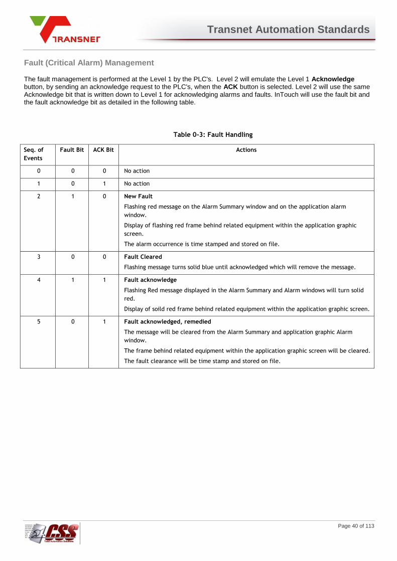
Transnet Automation Standards
Page 40 of 113
Fault (Critical Alarm) Management
The fault management is performed at the Level 1 by the PLC's. Level 2 will emulate the Level 1 Acknowledge button, by sending an acknowledge request to the PLC's, when the ACK button is selected. Level 2 will use the same Acknowledge bit that is written down to Level 1 for acknowledging alarms and faults. InTouch will use the fault bit and the fault acknowledge bit as detailed in the following table.
Table 0-3: Fault Handling
Seq. of
Events
Fault Bit ACK Bit Actions
0 0 0 No action
1 0 1 No action
2 1 0 New Fault
Flashing red message on the Alarm Summary window and on the application alarm
window.
Display of flashing red frame behind related equipment within the application graphic
screen.
The alarm occurrence is time stamped and stored on file.
3
0 0 Fault Cleared
Flashing message turns solid blue until acknowledged which will remove the message.
4 1 1 Fault acknowledge
Flashing Red message displayed in the Alarm Summary and Alarm windows will turn solid
red.
Display of soild red frame behind related equipment within the application graphic screen.
5 0 1 Fault acknowledged, remedied
The message will be cleared from the Alarm Summary and application graphic Alarm
window.
The frame behind related equipment within the application graphic screen will be cleared.
The fault clearance will be time stamp and stored on file.

Transnet Automation Standards
Page 41 of 113
Alarm Management
The alarm management is performed at the Level 1 by the PLC's. The Level 2 will emulate the Level 1 Acknowledge button, by sending an alarm acknowledge request to the PLC's, when the ACK button is selected. InTouch will use the alarm bit and the alarm acknowledge bit as detailed in the following table. The alarms acknowledge bit will be the exact same bit as the one used for fault acknowledgement.
Table 0-4: Alarm Handling
Seq. of
Events
Fault Bit ACK Bit Actions
0 0 0 No action
1 0 1 No action
2 1 0 New Alarm
Flashing red message on the Alarm Summary window and on the application alarm
window.
Display of flashing red frame behind related equipment within the application
graphic screen.
The alarm occurrence is time stamped and stored on file.
3
0 0 Alarm Cleared
Flashing message turns solid blue until acknowledged which will remove the
message.
4 1 1 Alarm acknowledge
Flashing Red message displayed in the Alarm Summary and Alarm windows will
turn solid red.
Display of soild red frame behind related equipment within the application
graphic screen.
5 0 1 Alarm acknowledged, remedied
The message will be cleared from the Alarm Summary and application graphic
Alarm window.
The frame behind related equipment within the application graphic screen will be
cleared.
The fault clearance will be time stamp and stored on file.
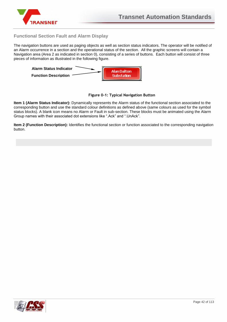
Transnet Automation Standards
Page 42 of 113
Functional Section Fault and Alarm Display
The navigation buttons are used as paging objects as well as section status indicators. The operator will be notified of an Alarm occurrence in a section and the operational status of the section. All the graphic screens will contain a Navigation area (Area 2 as indicated in section 0), consisting of a series of buttons. Each button will consist of three pieces of information as illustrated in the following figure.
Figure 0-1: Typical Navigation Button
Item 1 (Alarm Status Indicator): Dynamically represents the Alarm status of the functional section associated to the corresponding button and use the standard colour definitions as defined above (same colours as used for the symbol status blocks). A blank icon means no Alarm or Fault in sub-section. These blocks must be animated using the Alarm Group names with their associated dot extensions like “.Ack” and “.UnAck”. Item 2 (Function Description): Identifies the functional section or function associated to the corresponding navigation button.
Alarm Status Indicator
Function Description
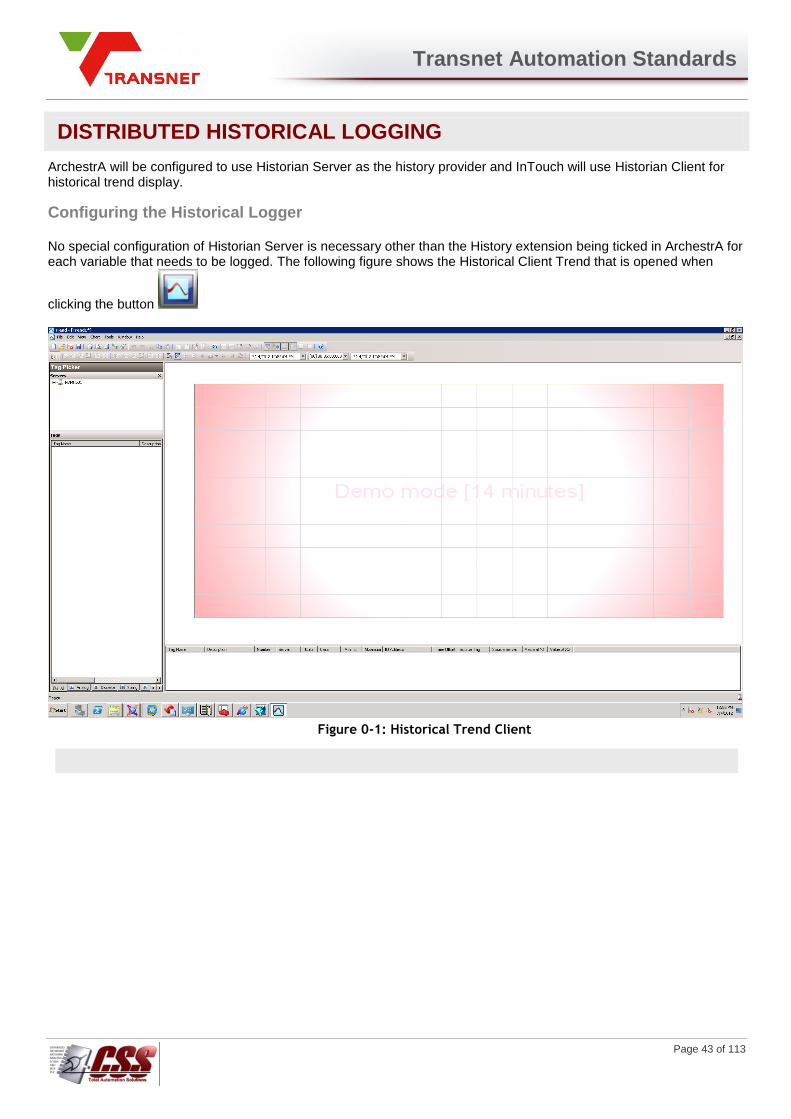
Transnet Automation Standards
Page 43 of 113
DISTRIBUTED HISTORICAL LOGGING
ArchestrA will be configured to use Historian Server as the history provider and InTouch will use Historian Client for historical trend display.
Configuring the Historical Logger
No special configuration of Historian Server is necessary other than the History extension being ticked in ArchestrA for each variable that needs to be logged. The following figure shows the Historical Client Trend that is opened when
clicking the button
Figure 0-1: Historical Trend Client
Transnet Automation Standards
Page 44 of 113
SECURITY
The SCADA Security system will allow the ability to control whether users are allowed to perform specific functions within an application. Audit trails are created which will tie the user to all alarms/events that occurred during the time he/she was logged on to the system. For this purpose the ArchestrA Galaxy security will be used.
Galaxy Security
When the Industrial Application Server security mode is set to Galaxy, then the IDE will be used to create and manage
the users. There are few restrictions of passwords of Galaxy users. For example, there is no minimum character
length, and the passwords never expire. Galaxy users are global. This means that these users will be known at every
computer in the Galaxy. Users can be created at any development node that has the IDE loaded and can establish a
connection to the Galaxy Repository for the application.
Galaxy security is most appropriate for applications that do not have strict requirements for password policies. Also, the users are defined with the IDE, so the person managing the users will have to have access to the configuration tools. ArchestrA security is designed to prevent users from performing unauthorized activities, including users of:
The IDE when configuring and managing objects.
The ArchestrA System Management Console (SMC) when performing maintenance and system
administration functions.
Any runtime operations.
Security not only controls access to user interfaces in the ArchestrA environment but also access to object attributes and the data they represent. The security icons associated with object attributes (see "Working with Object Editors" in the ArchestrA documentation) map directly to control points in the ArchestrA security model. Each Galaxy in the Galaxy Repository manages its own security model. The security schema managed in a Galaxy is a three-level configuration model that includes the creation and maintenance of the following:
security groups associated with specific objects in the Galaxy
user roles associated with specific system administration, configuration and runtime (operational)
permissions, which map to security groups
users associated with specific roles
This kind of security matrix defines a cascading model of users associated with specific roles that are associated with specific security groups associated with specific objects. This kind of model allows a user’s runtime permissions to vary from object to object, action to action and process to process. The following basic concepts are important for understanding the ArchestrA security model:
Users
A user is each individual person that will be using the system. For example, John Smith and Peter Perez.
Roles
Roles define groups of users within the security system. Roles usually reflect the type of work performed by different groups within your factory environment. For example, Operators and Technicians.
Permissions
Permissions determine what users are allowed to do within the system. For example, Operate, Tune, and Configure.
Security Groups
A security group is a logical Area to which you want to assign users and/or roles. Security groups typically map on to Areas and reflect a physical location of your plant. For example, you might want to assign Technicians to the Line_1 security group, but not to the Line_2 security group.
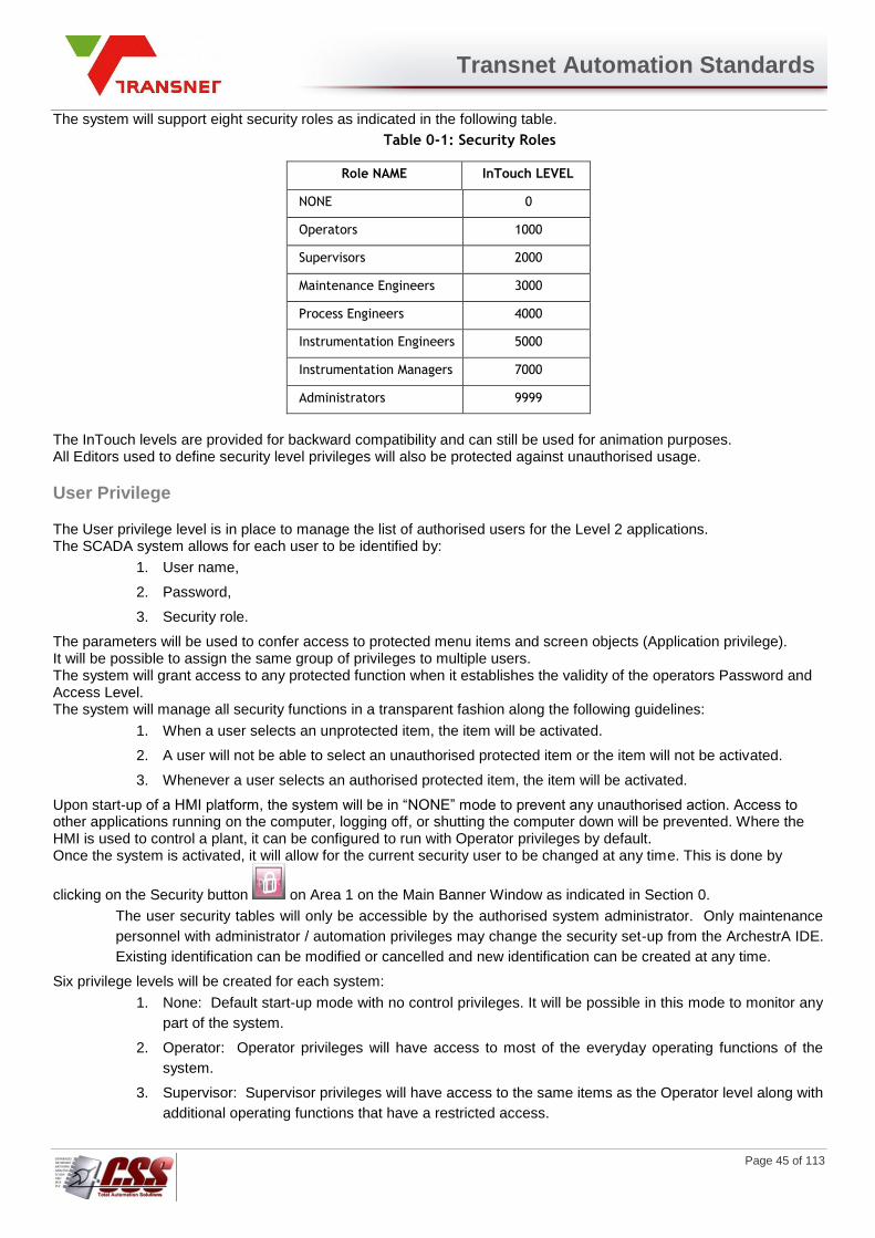
Transnet Automation Standards
Page 45 of 113
The system will support eight security roles as indicated in the following table.
Table 0-1: Security Roles
Role NAME InTouch LEVEL
NONE 0
Operators 1000
Supervisors 2000
Maintenance Engineers 3000
Process Engineers 4000
Instrumentation Engineers 5000
Instrumentation Managers 7000
Administrators 9999
The InTouch levels are provided for backward compatibility and can still be used for animation purposes. All Editors used to define security level privileges will also be protected against unauthorised usage.
User Privilege
The User privilege level is in place to manage the list of authorised users for the Level 2 applications. The SCADA system allows for each user to be identified by:
1. User name,
2. Password,
3. Security role.
The parameters will be used to confer access to protected menu items and screen objects (Application privilege). It will be possible to assign the same group of privileges to multiple users. The system will grant access to any protected function when it establishes the validity of the operators Password and Access Level. The system will manage all security functions in a transparent fashion along the following guidelines:
1. When a user selects an unprotected item, the item will be activated.
2. A user will not be able to select an unauthorised protected item or the item will not be activated.
3. Whenever a user selects an authorised protected item, the item will be activated.
Upon start-up of a HMI platform, the system will be in “NONE” mode to prevent any unauthorised action. Access to other applications running on the computer, logging off, or shutting the computer down will be prevented. Where the HMI is used to control a plant, it can be configured to run with Operator privileges by default. Once the system is activated, it will allow for the current security user to be changed at any time. This is done by
clicking on the Security button on Area 1 on the Main Banner Window as indicated in Section 0.
The user security tables will only be accessible by the authorised system administrator. Only maintenance
personnel with administrator / automation privileges may change the security set-up from the ArchestrA IDE.
Existing identification can be modified or cancelled and new identification can be created at any time.
Six privilege levels will be created for each system:
1. None: Default start-up mode with no control privileges. It will be possible in this mode to monitor any
part of the system.
2. Operator: Operator privileges will have access to most of the everyday operating functions of the
system.
3. Supervisor: Supervisor privileges will have access to the same items as the Operator level along with
additional operating functions that have a restricted access.

Transnet Automation Standards
Page 46 of 113
4. Maintenance: Maintenance privileges will have access to the same items as the Operator and
Supervisor level options, as well as all other maintenance related options.
5. Specialist: Specialist privileges will have access to the Operator, Supervisor and Maintenance level
options, as well as PID settings, Setpoints and related options.
6. Administrator / Automation: Administrator privileges will have access to all levels of the system.
They will have access to the Operator, Supervisor and Maintenance level options, as well as all other
administrator-related options. These include shutting the InTouch run-time system down by selecting
the Quit button on the Overview screen, access to other applications on the computer, and shutting
the computer down. The <Alt><Tab>, <Cntrl><Esc>, and <Cntrl><Alt><Del> functions will also be
enabled.
The standard InTouch Run-time menus will not be utilised. Instead, navigation through the system will be
by clicking on specific objects. These objects’ touch functionality can be disabled, based upon the
security level assigned to these objects.
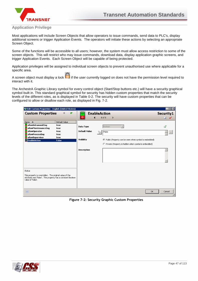
Transnet Automation Standards
Page 47 of 113
Application Privilege
Most applications will include Screen Objects that allow operators to issue commands, send data to PLC's, display additional screens or trigger Application Events. The operators will initiate these actions by selecting an appropriate Screen Object. Some of the functions will be accessible to all users; however, the system must allow access restriction to some of the screen objects. This will restrict who may issue commands, download data, display application graphic screens, and trigger Application Events. Each Screen Object will be capable of being protected. Application privileges will be assigned to individual screen objects to prevent unauthorised use where applicable for a specific area.
A screen object must display a lock if the user currently logged on does not have the permission level required to interact with it. The ArchestrA Graphic Library symbol for every control object (Start/Stop buttons etc.) will have a security graphical symbol built in. This standard graphical symbol for security has hidden custom properties that match the security levels of the different roles, as is displayed in Table 0-2. The security will have custom properties that can be configured to allow or disallow each role, as displayed in Fig. 7-2.
Figure 7-2: Security Graphic Custom Properties
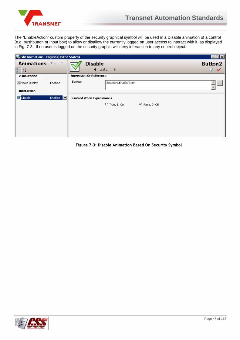
Transnet Automation Standards
Page 48 of 113
The “EnableAction” custom property of the security graphical symbol will be used in a Disable animation of a control (e.g. pushbutton or input box) to allow or disallow the currently logged on user access to interact with it, as displayed in Fig. 7-3. If no user is logged on the security graphic will deny interaction to any control object.
Figure 7-3: Disable Animation Based On Security Symbol

Transnet Automation Standards
Page 49 of 113
Electrical Switching Security System
The switching of electrical supply from the SCADA system can only be done under user specific access. User access for electrical switching is managed through a supplementary system in ArchestrA and InTouch. Only users of the Instrumentation Engineers and Instrumentation Managers roles are eligible to be granted access to electrical switching. A user can be granted access to electrical switching for switch gear in a specific area, and denied access to switch gear of all other areas. It must also be specified from which InTouch SCADA a user has permission to electrical switching for each area. The management of Electrical Switching Security System is done on the Security Edit page of the InTouch SCADA application. Only users of the Instrumentation Managers role can edit the Electrical Switching Security System.
If the current logged on user does not have access to switch gear of a certain area a symbol is shown on SCADA on the particular screen object. . Adding an Area to the Electrical Switching Security System The following is the procedure that is to be followed when a new area is added to the ArchestrA system in order to incorporate it into the Electrical Switching Security System
1. In InTouch Window Maker of the Transnet application, open Recipe Manager and browse to the location of the file User_Area_Recipenames.csv and open it.
2. In the template definition, add an Item Name for the new area, for example “New Area”. The type must be message. In the Unit definition, add the next InTouch tag called “USER_AREA_TAGXXX” that is not used already, in this case it is “USER_AREA_TAG004”. See Figure 7-4.
Figure 7-4: User_Area_Recipenames.csv
3. On the Security Edit window in Window Maker, copy a new area selection line, and rename the area to the name of the new area, in this example “New Area Added (New Area)”. See Figure 7-5.
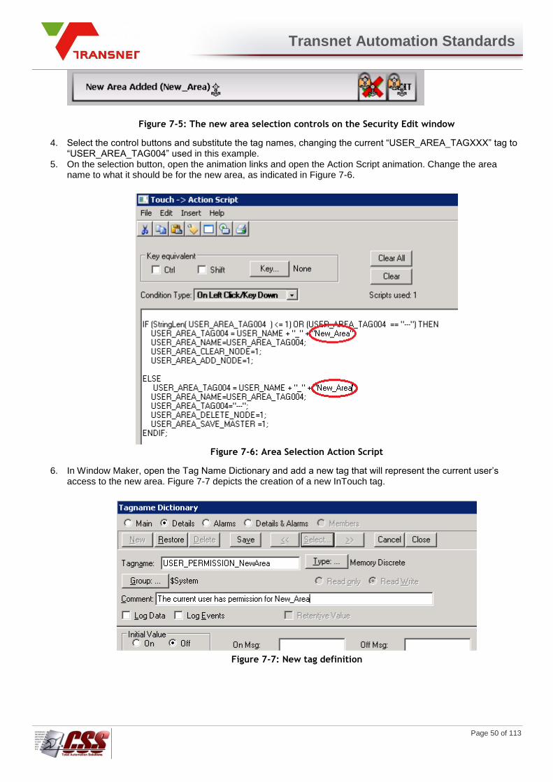
Transnet Automation Standards
Page 50 of 113
Figure 7-5: The new area selection controls on the Security Edit window
4. Select the control buttons and substitute the tag names, changing the current “USER_AREA_TAGXXX” tag to “USER_AREA_TAG004” used in this example.
5. On the selection button, open the animation links and open the Action Script animation. Change the area name to what it should be for the new area, as indicated in Figure 7-6.
Figure 7-6: Area Selection Action Script
6. In Window Maker, open the Tag Name Dictionary and add a new tag that will represent the current user’s access to the new area. Figure 7-7 depicts the creation of a new InTouch tag.
Figure 7-7: New tag definition

Transnet Automation Standards
Page 51 of 113
7. Edit the Condition Script “USER_PERMISSION_UPDATE == 1” by adding an If Statement and an Else for the new area, as indicated in Figure 7-8.
Figure 7-8: Editing the Condition Script “USER_PERMISSION_UPDATE == 1”
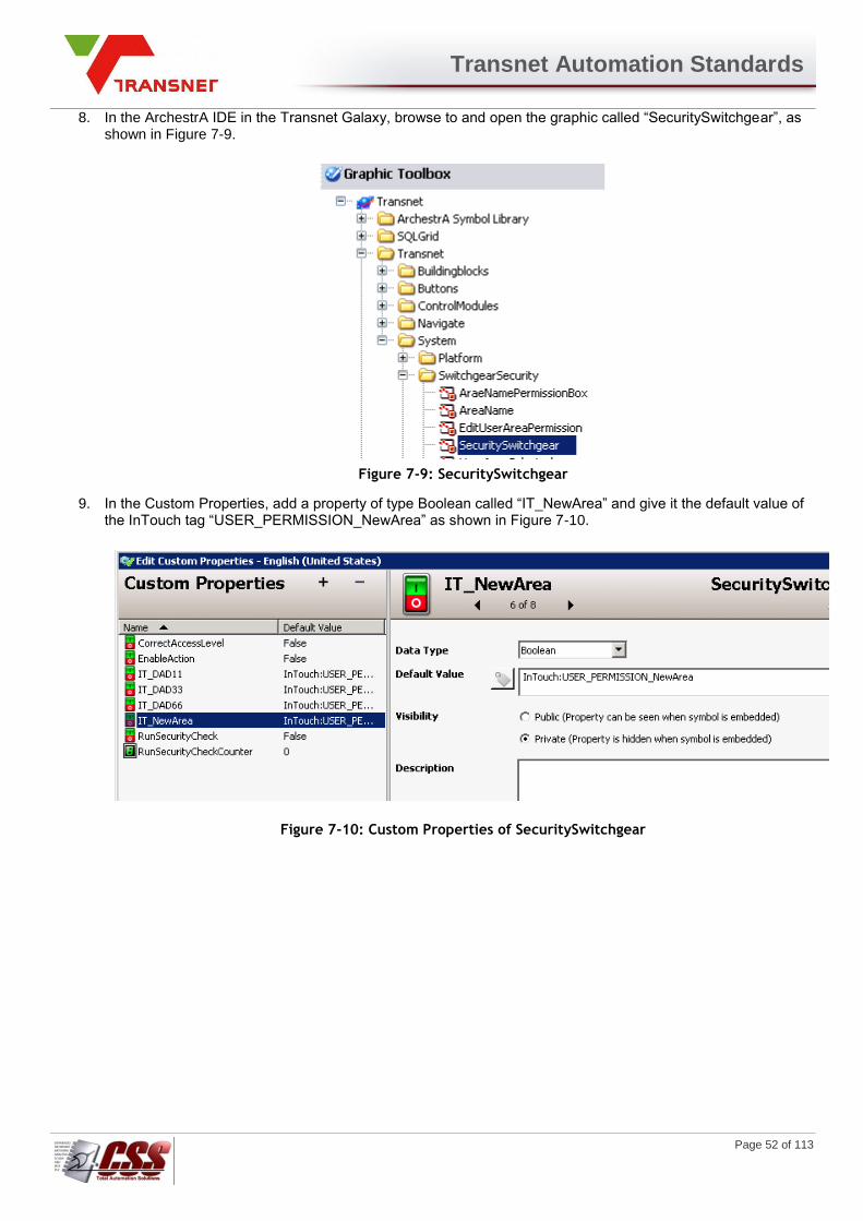
Transnet Automation Standards
Page 52 of 113
8. In the ArchestrA IDE in the Transnet Galaxy, browse to and open the graphic called “SecuritySwitchgear”, as shown in Figure 7-9.
Figure 7-9: SecuritySwitchgear
9. In the Custom Properties, add a property of type Boolean called “IT_NewArea” and give it the default value of the InTouch tag “USER_PERMISSION_NewArea” as shown in Figure 7-10.
Figure 7-10: Custom Properties of SecuritySwitchgear

Transnet Automation Standards
Page 53 of 113
10. Open the Edit Scripts window and open the script called “CheckSecurity”. The script has to be edited by adding an Elseif statement as shown in Figure 7-11.
Figure 7-11: Script “CheckSecurity”

Transnet Automation Standards
Page 54 of 113
11. All the Automation Object instances created in the Transnet Galaxy that fall part of the area “New_Area” must have their UDA called “AreaName” changed to “New_Area”.
Adding an InTouch View Node to the Electrical Switching Security System The following is the procedure that is to be followed when a new InTouch View Node is added to the ArchestrA system in order to incorporate it into the Electrical Switching Security System.
1. In the ArchestrA IDE in the Transnet Galaxy, browse to and open the graphic called “ViewNodePermissions” as shown in Figure 7-12.
Figure 7-12: Graphic “ViewNodePermissions”
2. On the next unused View Node, change the name of the “ViewNode” to the actual name of the new node. Figure 7-13 shows the next available View Node in the graphic.
Figure 7-13: Next View Node to add.

Transnet Automation Standards
Page 55 of 113
3. In the InTouch Window Maker, open the Quickfunction “UserAreaViewNodePermissions”. An If Statement has to be added for the new view node, and the next unused tag “USER_AREA_NODE_TAGXXX” has to be used. The Figure 7-14 shows the If Statement that is added, and the tag “USER_AREA_NODE_TAG002” is the next unused tag, which is then used in the If statement.
Figure 7-14: Quickfunction “UserAreaViewNodePermissions”.
Transnet Automation Standards
Page 56 of 113
Runtime Security (Operational Permissions)
The following is a list of the Operational Permissions that can be associated with a role:
Can Modify "Operate" Attributes:
Allows users with operational permissions to do certain normal day-to-day tasks like changing SetPoint, output and control mode for a PID object, or commanding a Discrete Device object.
Can Modify "Tune" Attributes:
Allows users to tune the attribute in the runtime environment. Examples of tuning are attributes that adjust alarm SetPoints and PID sensitivity.
Can Modify "Configure" Attributes:
Allows users to configure the attribute’s value. Requires that the user first put the object off scan. Writing to these attributes is considered a significant configuration change (for example, a PLC register that defines a Discrete Device input).
Can Acknowledge Alarms:
Allows users to manually acknowledge an alarm in the runtime environment.
Inactivity Timeout
The InTouch inactivity timeout function can be enabled to automatically log off the currently logged on user after a fixed period of no activity from the keyboard or mouse. This is a generic setting for all users per application and it cannot distinguish between users. The need for this functionality should be established for each application individually and should be used with care on local HMI applications.
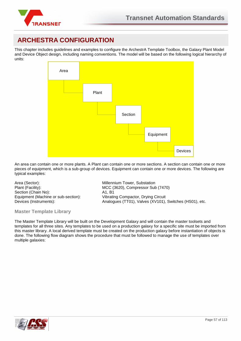
Transnet Automation Standards
Page 57 of 113
ARCHESTRA CONFIGURATION
This chapter includes guidelines and examples to configure the ArchestrA Template Toolbox, the Galaxy Plant Model and Device Object design, including naming conventions. The model will be based on the following logical hierarchy of units:
Area
Plant
Section
Equipment
Devices
An area can contain one or more plants. A Plant can contain one or more sections. A section can contain one or more pieces of equipment, which is a sub-group of devices. Equipment can contain one or more devices. The following are typical examples: Area (Sector): Millennium Tower, Substation Plant (Facility): MCC (3620), Compressor Sub (7470) Section (Chain No): A1, B1 Equipment (Machine or sub-section): Vibrating Compactor, Drying Circuit Devices (Instruments): Analogues (TT01), Valves (XV101), Switches (HS01), etc.
Master Template Library
The Master Template Library will be built on the Development Galaxy and will contain the master toolsets and templates for all three sites. Any templates to be used on a production galaxy for a specific site must be imported from this master library. A local derived template must be created on the production galaxy before instantiation of objects is done. The following flow diagram shows the procedure that must be followed to manage the use of templates over multiple galaxies:

Transnet Automation Standards
Page 58 of 113
Master Template
Library
OK
N
Verify Functionality
at Staging Engine
Deliver to
Production Sites
Verify Functionality
at Production
Engines
OK
Create
Derived
Tempates
Implement
Changes on Local
Template
N
Document
Changes on Local
Template
Document
Templates
Collect
Changes
from
Production
Sites
Evaluate Changes
and Impact for all
Sites
Determine if
Template Change
Required
Update
Master
Template
Development Galaxy
Export/Import
Production Galaxy
The template library will be custom build with template objects as required and will be a library of System, Area, Equipment and Device objects common to all three sites. It will be logically broken down into toolsets as follows:
1. System Templates. This toolset will contain system and integration type object templates such as
Platform, Application engine and Communication objects.
2. Area Templates. This toolset will contain object templates for area type objects such as Area, Plant
and Section objects. A plant is a unit in an area and a section is a sub unit (chain) in a plant.
3. Unit Templates. This toolset will contain object templates for section (chain) or equipment type groups.
Equipment is a sub grouping of devices inside a section, such as a machine or a sub-system.
4. Device Templates. This toolset will contain the base object templates for all field devices such as
Drive, Valve, Analog, PID, Switch, Contactor, etc. These templates will be derived from the standard
application objects supplied with the ArchestrA system.
The design of each of the template objects will be detailed in section 0 of this document. The following picture shows an ArchestrA IDE (Integrated Development Environment) view of the Template Toolbox. This toolbox is a dynamic template that will grow or change with engineering requirements.
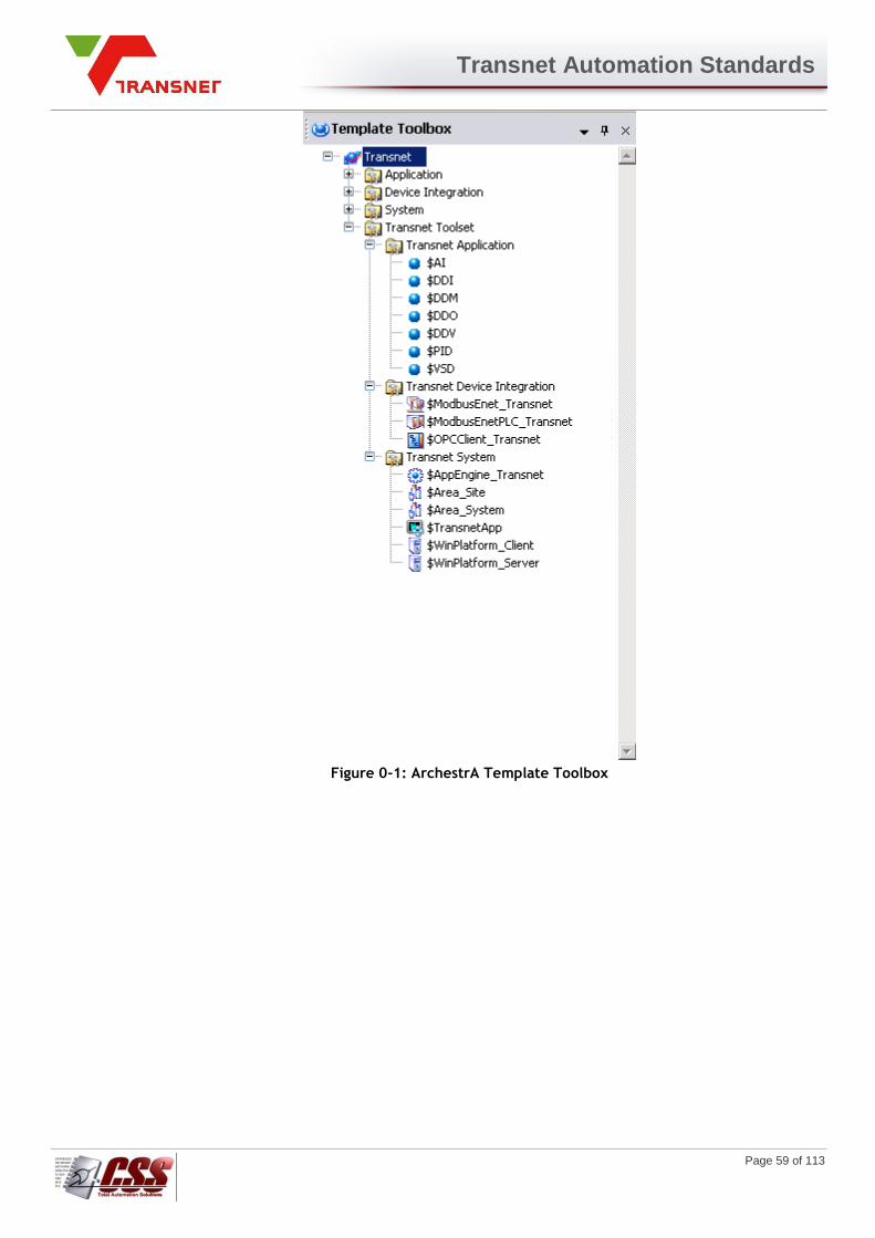
Transnet Automation Standards
Page 59 of 113
Figure 0-1: ArchestrA Template Toolbox
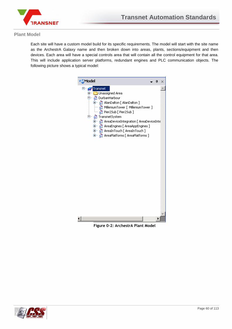
Transnet Automation Standards
Page 60 of 113
Plant Model
Each site will have a custom model build for its specific requirements. The model will start with the site name
as the ArchestrA Galaxy name and then broken down into areas, plants, sections/equipment and then
devices. Each area will have a special controls area that will contain all the control equipment for that area.
This will include application server platforms, redundant engines and PLC communication objects. The
following picture shows a typical model:
Figure 0-2: ArchestrA Plant Model

Transnet Automation Standards
Page 61 of 113
Device Templates
Each type of field instrument will be represented as an ArchestrA device object, designed with the appropriate properties as required. This section will show the detailed design of each of these device templates. All ArchestrA templates contain certain standard properties like PV, Short Description, Engineering units, etc. This section will only list non-standard properties such as all User Defined Attributes (UDA’s), which is a list of custom properties assigned to each object. The alarm description field for each alarm attribute in an object must be set by an execution script to describe the context of the alarm as in the format: Area + Equipment + Module + Alarm Description. The detailed breakdown of the interface words is based on the PLC Software Configuration document. The same property detail will be used inside the device objects configuration in InTouch. The list will also show the Extension configuration for each UDA. The extension configuration determines whether the attribute is an input only, an input and output, output only, alarm bit and whether it should be historized in the Historian server. The following table shows the possible Extension types and abbreviations used:
Extension Type Abbreviation
Input / Output I/O
Input I
Output O
Alarm A
Event E
History H
Not assigned (Blank space)
Table 0-1: Extension Abbreviations
Each attribute also needs to have a default security permission level assigned to it. The following table shows the possible permission types and the abbreviations used for it:
Permission Type Abbreviation
Operate OP
Tune T
Configure C
View Only V
Table 0-2: Security Permission Abbreviations
These templates will be used as master objects when instantiating the devices in the plant model.

Transnet Automation Standards
Page 62 of 113
STANDARDS & CONVENTIONS
This chapter includes guidelines and examples to configure the ArchestrA Transnet Toolbox, the PLC Transnet Toolset and device object design, including naming conventions and addressing structure.
Valve Device
Typical application for the valve object includes:
1. Valves 2. Dampers 3. Gates
PLC Graphical User Interface:
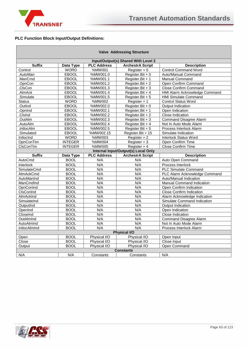
Transnet Automation Standards
Page 63 of 113
PLC Function Block Input/Output Definitions:
Valve Addressing Structure
Input/Output(s) Shared With Level 2
Suffix Data Type PLC Address ArchestrA Script Description
Control WORD %MW001 Register + 0 Control Command Word
.AutoMan EBOOL %MW001.0 Register.Bit + 0 Auto/Manual Command
.ManCmd EBOOL %MW001.1 Register.Bit + 1 Manual Command
.OpnCon EBOOL %MW001.2 Register.Bit + 2 Open Confirm Command
.ClsCon EBOOL %MW001.3 Register.Bit + 3 Close Confirm Command
.AlmAck EBOOL %MW001.4 Register.Bit + 4 HMI Alarm Acknowledge Command
.Simulate EBOOL %MW001.5 Register.Bit + 5 HMI Simulate Command
Status WORD %MW002 Register + 1 Control Status Word
.OutInd EBOOL %MW002.0 Register.Bit + 0 Output Indication
.OpnInd EBOOL %MW002.1 Register.Bit + 1 Open Indication
.ClsInd EBOOL %MW002.2 Register.Bit + 2 Close Indication
.OutAlm EBOOL %MW002.3 Register.Bit + 3 Command Disagree Alarm
.AutoAlm EBOOL %MW002.4 Register.Bit + 4 Not In Auto Mode Alarm
.IntlocAlm EBOOL %MW002.5 Register.Bit + 5 Process Interlock Alarm
.Simulated EBOOL %MW002.15 Register.Bit + 15 Simulate Indication
IntlocInd WORD %MW003 Register + 2 Interlock Status Word
OpnConTim INTEGER %MW004 Register + 3 Open Confirm Time
ClsConTim INTEGER %MW005 Register + 4 Close Confirm Time
Internal Input/Output(s) Local Only
Suffix Data Type PLC Address ArchestrA Script Description
AutoCmd BOOL N/A N/A Auto Open Command
Interlock BOOL N/A N/A Process Interlock
SimulateCmd BOOL N/A N/A PLC Simulate Command
AlmAckCmd BOOL N/A N/A PLC Alarm Acknowledge Command
AutoManInd BOOL N/A N/A Auto/Manual Indication
ManCmdInd BOOL N/A N/A Manual Command Indication
OpnConInd BOOL N/A N/A Open Confirm Indication
ClsConInd BOOL N/A N/A Close Confirm Indication
AlmAckInd BOOL N/A N/A Alarm Acknowledge Indication
SimulateInd BOOL N/A N/A Simulate Command Indication
OutputInd BOOL N/A N/A Output Indication
OpenInd BOOL N/A N/A Open Indication
CloseInd BOOL N/A N/A Close Indication
OutAlmInd BOOL N/A N/A Command Disagree Alarm
AutoAlmInd BOOL N/A N/A Not In Auto Mode Alarm
IntlocAlmInd BOOL N/A N/A Process Interlock Alarm
Physical I/O
Open BOOL Physical I/O Physical /IO Open Input
Close BOOL Physical I/O Physical /IO Close Input
Output BOOL Physical I/O Physical /IO Open Command
Constants
N/A N/A Constants Constants N/A
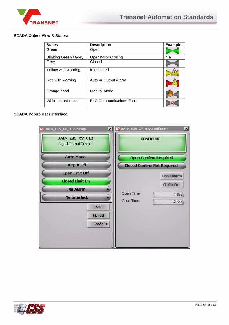
Transnet Automation Standards
Page 64 of 113
SCADA Object View & States:
States Description Example
Green Open
Blinking Green / Grey Opening or Closing n/a
Grey Closed
Yellow with warning Interlocked
Red with warning Auto or Output Alarm
Orange hand Manual Mode
White on red cross PLC Communications Fault
SCADA Popup User Interface:
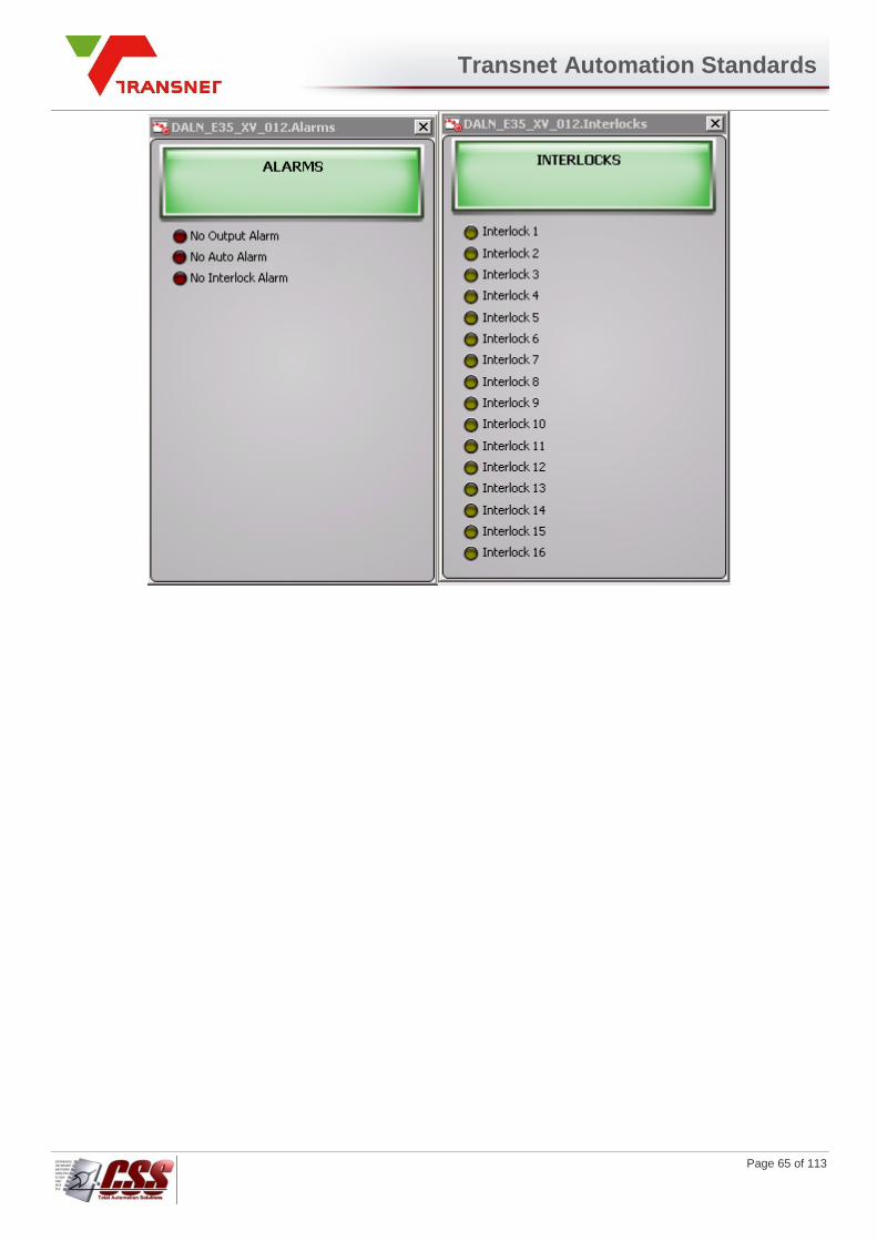
Transnet Automation Standards
Page 65 of 113
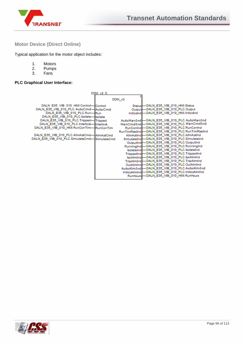
Transnet Automation Standards
Page 66 of 113
Motor Device (Direct Online)
Typical application for the motor object includes:
1. Motors 2. Pumps 3. Fans
PLC Graphical User Interface:
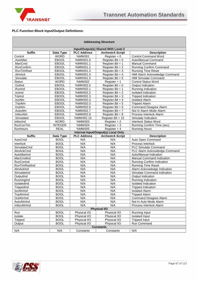
Transnet Automation Standards
Page 67 of 113
PLC Function Block Input/Output Definitions:
Addressing Structure
Input/Output(s) Shared With Level 2
Suffix Data Type PLC Address ArchestrA Script Description
Control WORD %MW001 Register + 0 Control Command Word
.AutoMan EBOOL %MW001.0 Register.Bit + 0 Auto/Manual Command
.ManCmd EBOOL %MW001.1 Register.Bit + 1 Manual Command
.RunConfirm EBOOL %MW001.2 Register.Bit + 2 Running Confirm Command
.RunTimRset EBOOL %MW001.3 Register.Bit + 3 Running Time Reset
.AlmAck EBOOL %MW001.4 Register.Bit + 4 HMI Alarm Acknowledge Command
.Simulate EBOOL %MW001.5 Register.Bit + 5 HMI Simulate Command
Status WORD %MW002 Register + 1 Control Status Word
.OutInd EBOOL %MW002.0 Register.Bit + 0 Output Indication
.RunInd EBOOL %MW002.1 Register.Bit + 1 Running Indication
.IsoInd EBOOL %MW002.2 Register.Bit + 2 Isolated Indication
TripInd EBOOL %MW002.3 Register.Bit + 3 Tripped Indication
.IsoAlm EBOOL %MW002.4 Register.Bit + 4 Isolated Alarm
.TripAlm EBOOL %MW002.5 Register.Bit + 5 Tripped Alarm
.OutAlm EBOOL %MW002.6 Register.Bit + 6 Command Disagree Alarm
.AutoAlm EBOOL %MW002.7 Register.Bit + 7 Not In Alarm Mode Alarm
.IntlocAlm EBOOL %MW002.8 Register.Bit + 8 Process Interlock Alarm
.Simulated EBOOL %MW002.15 Register.Bit + 15 Simulate Indication
IntlocInd WORD %MW003 Register + 2 Interlock Status Word
RunConTim INTEGER %MW004 Register + 3 Running Confirm Time (sec)
RunHours REAL %MW005 Register + 4 Running Hours
Internal Input/Output(s) Local Only
Suffix Data Type PLC Address ArchestrA Script Description
AutoCmd BOOL N/A N/A Auto Open Command
Interlock BOOL N/A N/A Process Interlock
SimulateCmd BOOL N/A N/A PLC Simulate Command
AlmAckCmd BOOL N/A N/A PLC Alarm Acknowledge Command
AutoManInd BOOL N/A N/A Auto/Manual Indication
ManCmdInd BOOL N/A N/A Manual Command Indication
RunConInd BOOL N/A N/A Running Confirm Indication
RunTimRsetInd BOOL N/A N/A Running Time Reset
AlmAckInd BOOL N/A N/A Alarm Acknowledge Indication
SimulateInd BOOL N/A N/A Simulate Command Indication
OutputInd BOOL N/A N/A Output Indication
RunningInd BOOL N/A N/A Running Indication
IsolatedInd BOOL N/A N/A Isolated Indication
TrippedInd BOOL N/A N/A Tripped Indication
IsoAlmInd BOOL N/A N/A Isolated Alarm
TripAlmInd BOOL N/A N/A Tripped Alarm
OutAlmInd BOOL N/A N/A Command Disagree Alarm
AutoAlmInd BOOL N/A N/A Not In Auto Mode Alarm
IntlocAlmInd BOOL N/A N/A Process Interlock Alarm
Physical I/O
Run BOOL Physical I/O Physical /IO Running Input
Isolate BOOL Physical I/O Physical /IO Isolated Input
Tripped BOOL Physical I/O Physical /IO Tripped Input
Output BOOL Physical I/O Physical /IO Run Command
Constants
N/A N/A Constants Constants N/A
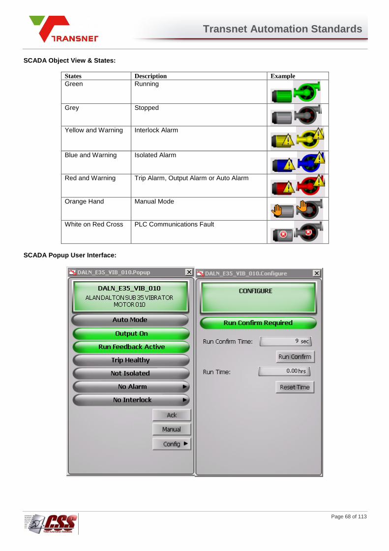
Transnet Automation Standards
Page 68 of 113
SCADA Object View & States:
States Description Example
Green Running
Grey Stopped
Yellow and Warning Interlock Alarm
Blue and Warning Isolated Alarm
Red and Warning Trip Alarm, Output Alarm or Auto Alarm
Orange Hand Manual Mode
White on Red Cross PLC Communications Fault
SCADA Popup User Interface:
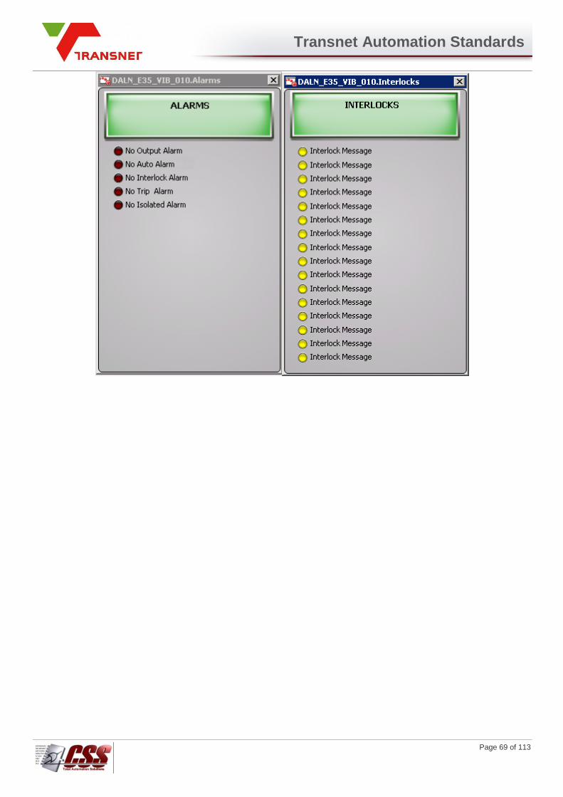
Transnet Automation Standards
Page 69 of 113
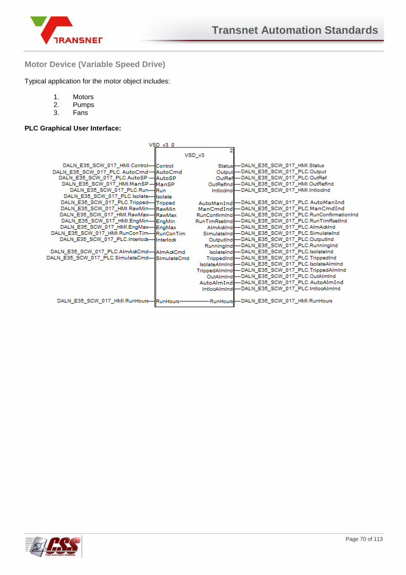
Transnet Automation Standards
Page 70 of 113
Motor Device (Variable Speed Drive)
Typical application for the motor object includes:
1. Motors 2. Pumps 3. Fans
PLC Graphical User Interface:

Transnet Automation Standards
Page 71 of 113
PLC Function Block Input/Output Definitions:
Addressing Structure
Input/Output(s) Shared With Level 2
Suffix Data Type PLC Address ArchestrA Script Description
Control WORD %MW001 Register + 0 Control Command Word
.AutoMan EBOOL %MW001.0 Register.Bit + 0 Auto/Manual Command
.ManCmd EBOOL %MW001.1 Register.Bit + 1 Manual Command
.RunConfirm EBOOL %MW001.2 Register.Bit + 2 Running Confirm Command
.RunTimRset EBOOL %MW001.3 Register.Bit + 3 Running Time Reset
.AlmAck EBOOL %MW001.4 Register.Bit + 4 HMI Alarm Acknowledge Command
.Simulate EBOOL %MW001.5 Register.Bit + 5 HMI Simulate Command
Status WORD %MW002 Register + 1 Control Status Word
.OutInd EBOOL %MW002.0 Register.Bit + 0 Output Indication
.RunInd EBOOL %MW002.1 Register.Bit + 1 Running Indication
.IsoInd EBOOL %MW002.2 Register.Bit + 2 Isolated Indication
TripInd EBOOL %MW002.3 Register.Bit + 3 Tripped Indication
.IsoAlm EBOOL %MW002.4 Register.Bit + 4 Isolated Alarm
.TripAlm EBOOL %MW002.5 Register.Bit + 5 Tripped Alarm
.OutAlm EBOOL %MW002.6 Register.Bit + 6 Command Disagree Alarm
.AutoAlm EBOOL %MW002.7 Register.Bit + 7 Not In Auto Mode Alarm
.IntlocAlm EBOOL %MW002.8 Register.Bit + 8 Process Interlock Alarm
.Simulated EBOOL %MW002.15 Register.Bit + 15 Simulate Indication
IntlocInd WORD %MW003 Register + 2 Interlock Status Word
RunConTim INTEGER %MW004 Register + 3 Running Confirm Time (sec)
RunHours REAL %MW005 Register + 4 Running Hours
ManSP REAL %MW007 Register + 6 Manual Setpoint
RawMin REAL %MW009 Register + 8 Raw Minimum
RawMax REAL %MW011 Register + 10 Raw Maximum
EngMin REAL %MW013 Register + 12 Engineering Minimum
EngMax REAL %MW015 Register + 14 Engineering Maximum
OutRefInd REAL %MW017 Register + 16 Output Reference Indication
Internal Input/Output(s) Local Only
Suffix Data Type PLC Address ArchestrA Script Description
AutoCmd BOOL N/A N/A Auto Open Command
AutoSP REAL N/A N/A Auto Setpoint
Interlock BOOL N/A N/A Process Interlock
SimulateCmd BOOL N/A N/A PLC Simulate Command
AlmAckCmd BOOL N/A N/A PLC Alarm Acknowledge Command
AutoManInd BOOL N/A N/A Auto/Manual Indication
ManCmdInd BOOL N/A N/A Manual Command Indication
RunConInd BOOL N/A N/A Running Confirm Indication
RunTimRsetInd BOOL N/A N/A Running Time Reset
AlmAckInd BOOL N/A N/A Alarm Acknowledge Indication
SimulateInd BOOL N/A N/A Simulate Command Indication
OutputInd BOOL N/A N/A Output Indication
RunningInd BOOL N/A N/A Running Indication
IsolatedInd BOOL N/A N/A Isolated Indication
TrippedInd BOOL N/A N/A Tripped Indication
IsoAlmInd BOOL N/A N/A Isolated Alarm
TripAlmInd BOOL N/A N/A Tripped Alarm
OutAlmInd BOOL N/A N/A Command Disagree Alarm
AutoAlmInd BOOL N/A N/A Not In Auto Mode Alarm
IntlocAlmInd BOOL N/A N/A Process Interlock Alarm
Physical I/O
Run BOOL Physical I/O Physical /IO Running Input
Isolate BOOL Physical I/O Physical /IO Isolated Input
Tripped BOOL Physical I/O Physical /IO Tripped Input
Output BOOL Physical I/O Physical /IO Run Command
OutRef WORD Physical I/O Physical /IO Output Referance
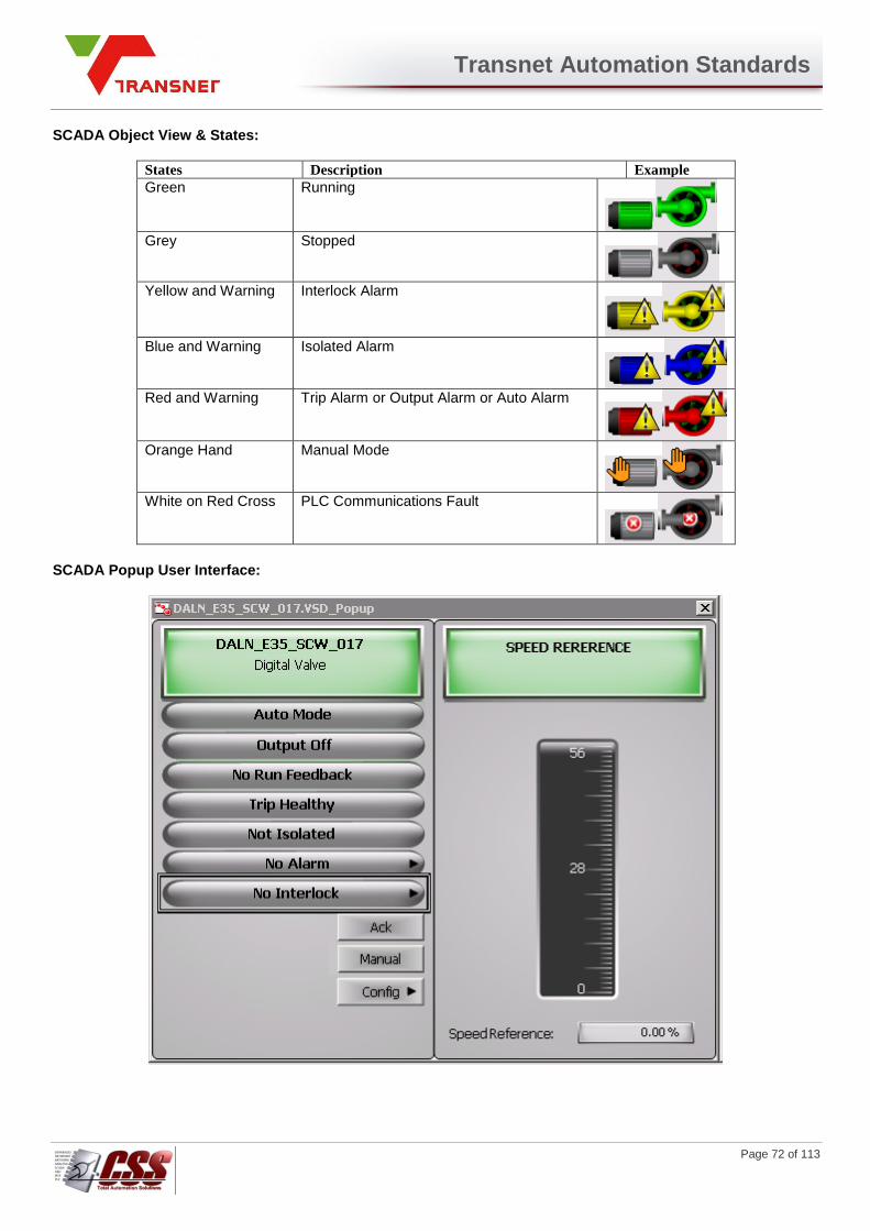
Transnet Automation Standards
Page 72 of 113
SCADA Object View & States:
States Description Example
Green Running
Grey Stopped
Yellow and Warning Interlock Alarm
Blue and Warning Isolated Alarm
Red and Warning Trip Alarm or Output Alarm or Auto Alarm
Orange Hand Manual Mode
White on Red Cross PLC Communications Fault
SCADA Popup User Interface:

Transnet Automation Standards
Page 73 of 113

Transnet Automation Standards
Page 74 of 113
Digital Input Device (DI)
Typical application for the digital input object includes:
1. Limit Switches 2. Level Switches 3. Push Buttons
PLC Graphical User Interface:
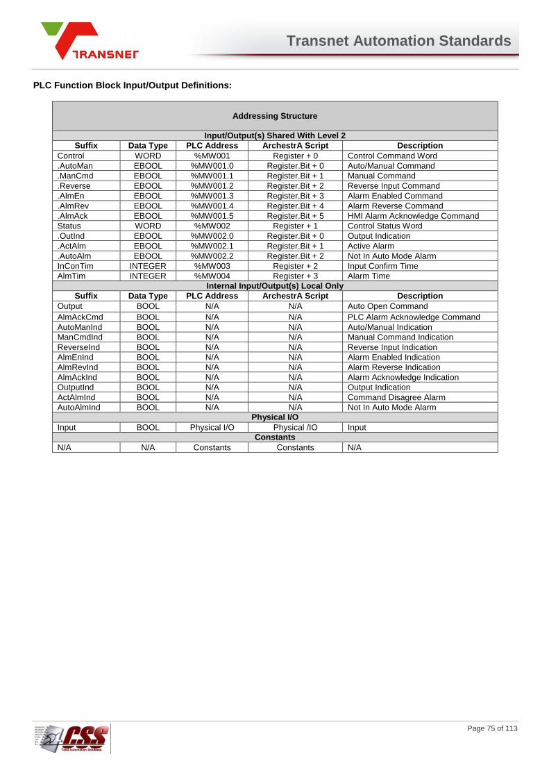
Transnet Automation Standards
Page 75 of 113
PLC Function Block Input/Output Definitions:
Addressing Structure
Input/Output(s) Shared With Level 2
Suffix Data Type PLC Address ArchestrA Script Description
Control WORD %MW001 Register + 0 Control Command Word
.AutoMan EBOOL %MW001.0 Register.Bit + 0 Auto/Manual Command
.ManCmd EBOOL %MW001.1 Register.Bit + 1 Manual Command
.Reverse EBOOL %MW001.2 Register.Bit + 2 Reverse Input Command
.AlmEn EBOOL %MW001.3 Register.Bit + 3 Alarm Enabled Command
.AlmRev EBOOL %MW001.4 Register.Bit + 4 Alarm Reverse Command
.AlmAck EBOOL %MW001.5 Register.Bit + 5 HMI Alarm Acknowledge Command
Status WORD %MW002 Register + 1 Control Status Word
.OutInd EBOOL %MW002.0 Register.Bit + 0 Output Indication
.ActAlm EBOOL %MW002.1 Register.Bit + 1 Active Alarm
.AutoAlm EBOOL %MW002.2 Register.Bit + 2 Not In Auto Mode Alarm
InConTim INTEGER %MW003 Register + 2 Input Confirm Time
AlmTim INTEGER %MW004 Register + 3 Alarm Time
Internal Input/Output(s) Local Only
Suffix Data Type PLC Address ArchestrA Script Description
Output BOOL N/A N/A Auto Open Command
AlmAckCmd BOOL N/A N/A PLC Alarm Acknowledge Command
AutoManInd BOOL N/A N/A Auto/Manual Indication
ManCmdInd BOOL N/A N/A Manual Command Indication
ReverseInd BOOL N/A N/A Reverse Input Indication
AlmEnInd BOOL N/A N/A Alarm Enabled Indication
AlmRevInd BOOL N/A N/A Alarm Reverse Indication
AlmAckInd BOOL N/A N/A Alarm Acknowledge Indication
OutputInd BOOL N/A N/A Output Indication
ActAlmInd BOOL N/A N/A Command Disagree Alarm
AutoAlmInd BOOL N/A N/A Not In Auto Mode Alarm
Physical I/O
Input BOOL Physical I/O Physical /IO Input
Constants
N/A N/A Constants Constants N/A

Transnet Automation Standards
Page 76 of 113
SCADA Object View & States:
States Description Example
Green Input On
Dark Green Input Off
Warning In Alarm
Orange Hand Manual Mode
White on Red Cross PLC Communications Fault
SCADA Popup User Interface:
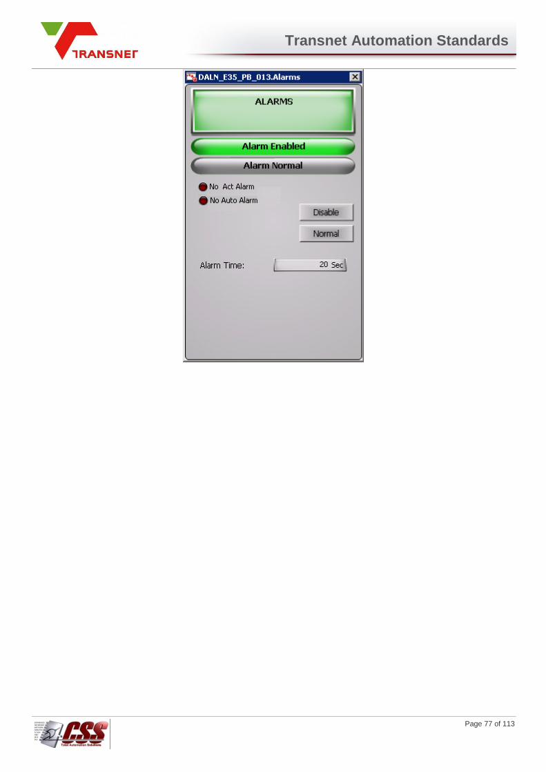
Transnet Automation Standards
Page 77 of 113
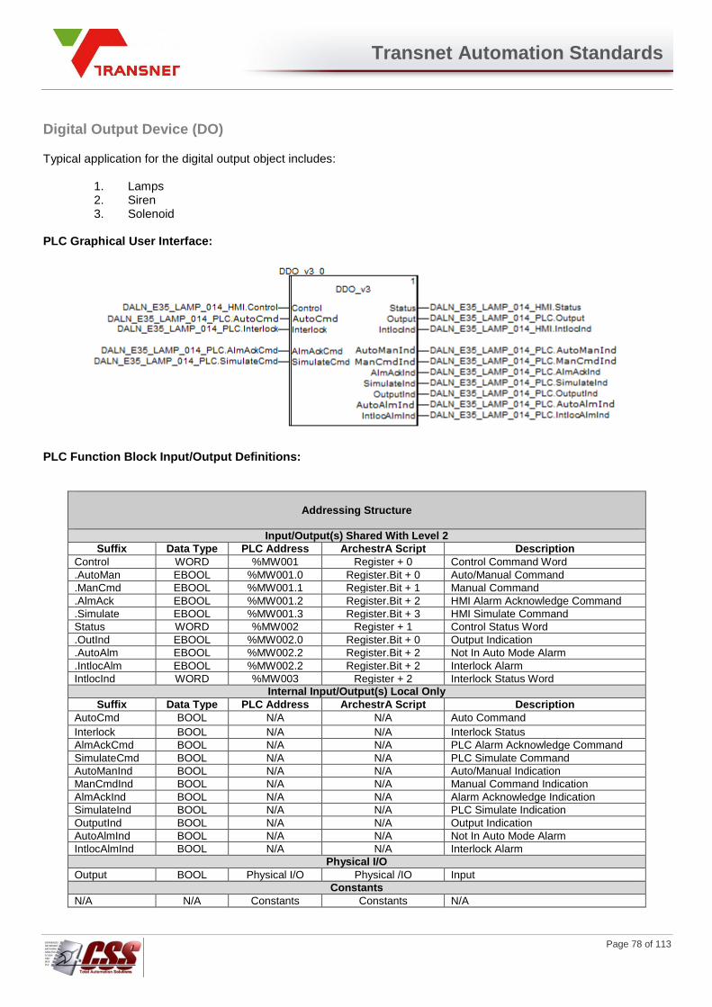
Transnet Automation Standards
Page 78 of 113
Digital Output Device (DO)
Typical application for the digital output object includes:
1. Lamps 2. Siren 3. Solenoid
PLC Graphical User Interface:
PLC Function Block Input/Output Definitions:
Addressing Structure
Input/Output(s) Shared With Level 2
Suffix Data Type PLC Address ArchestrA Script Description
Control WORD %MW001 Register + 0 Control Command Word
.AutoMan EBOOL %MW001.0 Register.Bit + 0 Auto/Manual Command
.ManCmd EBOOL %MW001.1 Register.Bit + 1 Manual Command
.AlmAck EBOOL %MW001.2 Register.Bit + 2 HMI Alarm Acknowledge Command
.Simulate EBOOL %MW001.3 Register.Bit + 3 HMI Simulate Command
Status WORD %MW002 Register + 1 Control Status Word
.OutInd EBOOL %MW002.0 Register.Bit + 0 Output Indication
.AutoAlm EBOOL %MW002.2 Register.Bit + 2 Not In Auto Mode Alarm
.IntlocAlm EBOOL %MW002.2 Register.Bit + 2 Interlock Alarm
IntlocInd WORD %MW003 Register + 2 Interlock Status Word
Internal Input/Output(s) Local Only
Suffix Data Type PLC Address ArchestrA Script Description
AutoCmd BOOL N/A N/A Auto Command
Interlock BOOL N/A N/A Interlock Status
AlmAckCmd BOOL N/A N/A PLC Alarm Acknowledge Command
SimulateCmd BOOL N/A N/A PLC Simulate Command
AutoManInd BOOL N/A N/A Auto/Manual Indication
ManCmdInd BOOL N/A N/A Manual Command Indication
AlmAckInd BOOL N/A N/A Alarm Acknowledge Indication
SimulateInd BOOL N/A N/A PLC Simulate Indication
OutputInd BOOL N/A N/A Output Indication
AutoAlmInd BOOL N/A N/A Not In Auto Mode Alarm
IntlocAlmInd BOOL N/A N/A Interlock Alarm
Physical I/O
Output BOOL Physical I/O Physical /IO Input
Constants
N/A N/A Constants Constants N/A
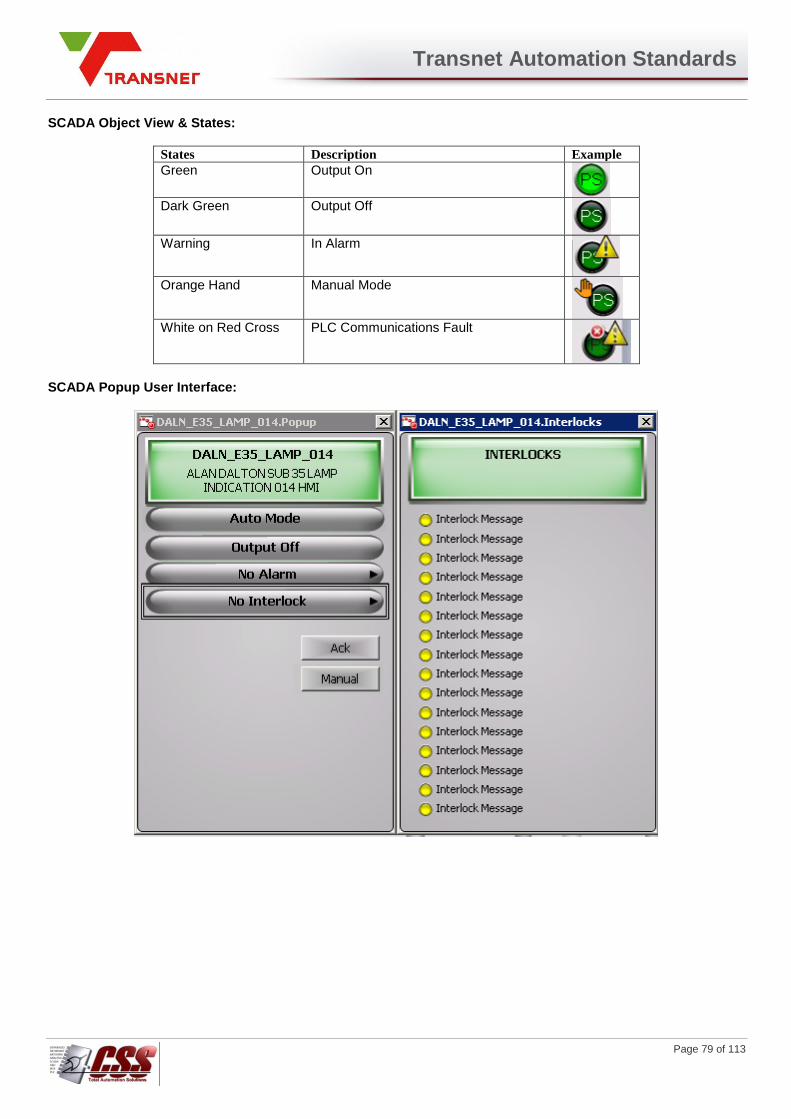
Transnet Automation Standards
Page 79 of 113
SCADA Object View & States:
States Description Example
Green Output On
Dark Green Output Off
Warning In Alarm
Orange Hand Manual Mode
White on Red Cross PLC Communications Fault
SCADA Popup User Interface:
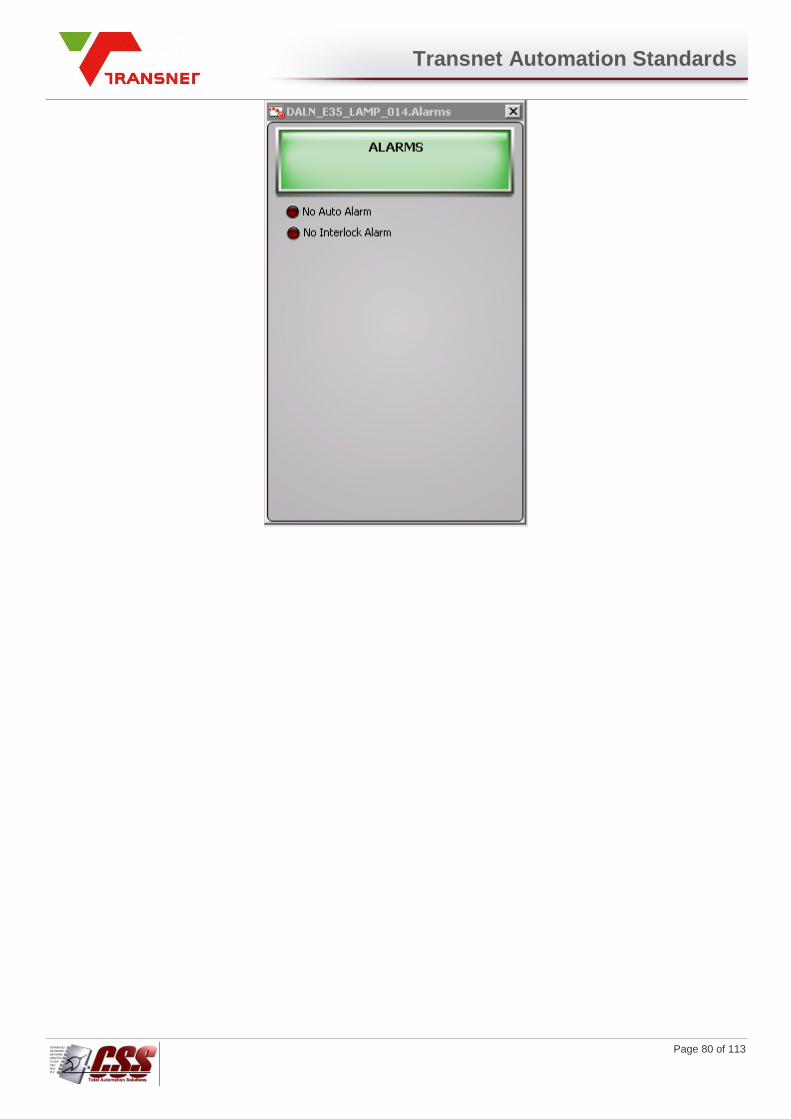
Transnet Automation Standards
Page 80 of 113
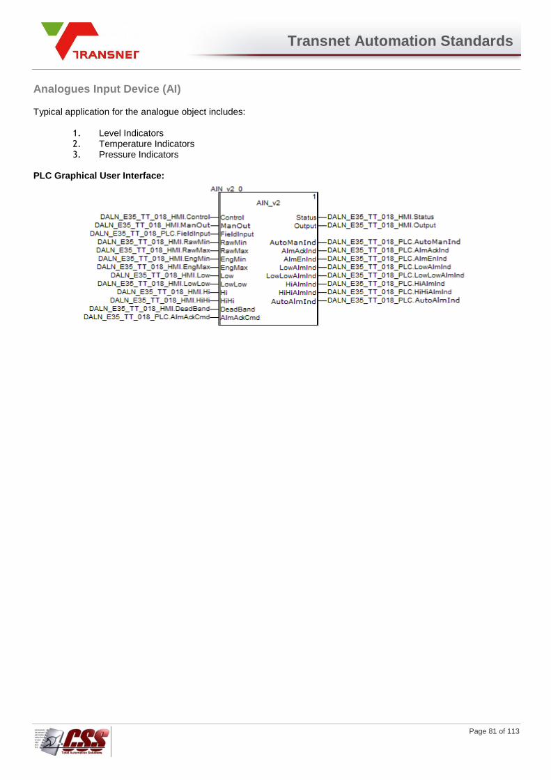
Transnet Automation Standards
Page 81 of 113
Analogues Input Device (AI)
Typical application for the analogue object includes:
1. Level Indicators 2. Temperature Indicators 3. Pressure Indicators
PLC Graphical User Interface:
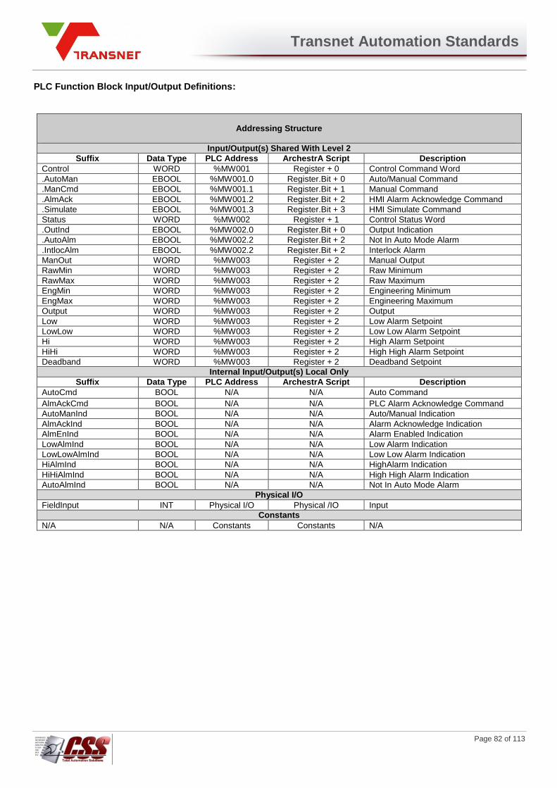
Transnet Automation Standards
Page 82 of 113
PLC Function Block Input/Output Definitions:
Addressing Structure
Input/Output(s) Shared With Level 2
Suffix Data Type PLC Address ArchestrA Script Description
Control WORD %MW001 Register + 0 Control Command Word
.AutoMan EBOOL %MW001.0 Register.Bit + 0 Auto/Manual Command
.ManCmd EBOOL %MW001.1 Register.Bit + 1 Manual Command
.AlmAck EBOOL %MW001.2 Register.Bit + 2 HMI Alarm Acknowledge Command
.Simulate EBOOL %MW001.3 Register.Bit + 3 HMI Simulate Command
Status WORD %MW002 Register + 1 Control Status Word
.OutInd EBOOL %MW002.0 Register.Bit + 0 Output Indication
.AutoAlm EBOOL %MW002.2 Register.Bit + 2 Not In Auto Mode Alarm
.IntlocAlm EBOOL %MW002.2 Register.Bit + 2 Interlock Alarm
ManOut WORD %MW003 Register + 2 Manual Output
RawMin WORD %MW003 Register + 2 Raw Minimum
RawMax WORD %MW003 Register + 2 Raw Maximum
EngMin WORD %MW003 Register + 2 Engineering Minimum
EngMax WORD %MW003 Register + 2 Engineering Maximum
Output WORD %MW003 Register + 2 Output
Low WORD %MW003 Register + 2 Low Alarm Setpoint
LowLow WORD %MW003 Register + 2 Low Low Alarm Setpoint
Hi WORD %MW003 Register + 2 High Alarm Setpoint
HiHi WORD %MW003 Register + 2 High High Alarm Setpoint
Deadband WORD %MW003 Register + 2 Deadband Setpoint
Internal Input/Output(s) Local Only
Suffix Data Type PLC Address ArchestrA Script Description
AutoCmd BOOL N/A N/A Auto Command
AlmAckCmd BOOL N/A N/A PLC Alarm Acknowledge Command
AutoManInd BOOL N/A N/A Auto/Manual Indication
AlmAckInd BOOL N/A N/A Alarm Acknowledge Indication
AlmEnInd BOOL N/A N/A Alarm Enabled Indication
LowAlmInd BOOL N/A N/A Low Alarm Indication
LowLowAlmInd BOOL N/A N/A Low Low Alarm Indication
HiAlmInd BOOL N/A N/A HighAlarm Indication
HiHiAlmInd BOOL N/A N/A High High Alarm Indication
AutoAlmInd BOOL N/A N/A Not In Auto Mode Alarm
Physical I/O
FieldInput INT Physical I/O Physical /IO Input
Constants
N/A N/A Constants Constants N/A

Transnet Automation Standards
Page 83 of 113
SCADA Object View & States:
States Description Example
Grey Healthy
Yellow and Warning
Low or High Alarm
Red and Warning
High High Alarm or Low Low Alarm or Auto Alarm
Orange Hand Manual Mode
White on Red Cross
PLC Communications Fault
SCADA Popup User Interface:

Transnet Automation Standards
Page 84 of 113

Transnet Automation Standards
Page 85 of 113
Proportional Integral Derivative Device (PID)
Typical application for the PID object includes:
1. Level Controller 2. Temperature Controller 3. Pressure Controller
PLC Graphical User Interface:

Transnet Automation Standards
Page 86 of 113
PLC Function Block Input/Output Definitions:
Addressing Structure
Input/Output(s) Shared With Level 2
Suffix Data Type PLC Address ArchestrA Script Description
Control WORD %MW001 Register + 0 Control Command Word
.AutoMan EBOOL %MW001.0 Register.Bit + 0 Auto/Manual Command
.Halt EBOOL %MW001.1 Register.Bit + 1 Manual Command
.AlmAck EBOOL %MW001.2 Register.Bit + 2 HMI Alarm Acknowledge Command
Status WORD %MW002 Register + 1 Control Status Word
.AutoAlm EBOOL %MW002.1 Register.Bit + 1 Not In Auto Mode Alarm
.Simulated EBOOL %MW002.15 Register.Bit + 15 Simulate Indication
Setpoint REAL %MW003 Register + 3 Controller Setpoint
ManOut REAL %MW005 Register + 5 Manual Output
ProcVar REAL %MW007 Register + 7 Process Variable
Bias REAL %MW009 Register + 9 Bias
Gain REAL %MW011 Register + 11 Gain
IntTim INTEGER %MW013 Register + 13 Integral Time (s)
DerTim INTEGER %MW014 Register + 14 Derivative Time (s)
RawMin REAL %MW015 Register + 15 Raw Minimum
RawMax REAL %MW017 Register + 17 Raw Maximum
EngMin REAL %MW019 Register + 19 Engineering Minimum
EngMax REAL %MW021 Register + 21 Engineering Maximum
OutInd REAL %MW023 Register + 23 Controller Output Indication
Error REAL %MW025 Register + 25 Controller Error
Internal Input/Output(s) Local Only
Suffix Data Type PLC Address ArchestrA Script Description
HaltCmd BOOL N/A N/A Halt Command
SimulateCmd BOOL N/A N/A PLC Simulate Command
AlmAckCmd BOOL N/A N/A PLC Alarm Acknowledge Command
AutoManInd BOOL N/A N/A Auto/Manual Indication
HaltInd BOOL N/A N/A Halt Indication
AlmAckInd BOOL N/A N/A Alarm Acknowledge Indication
AutoAlmInd BOOL N/A N/A Not In Auto Mode Alarm
SimulateInd BOOL N/A N/A Simulate Command Indication
Physical I/O
Output WORD Physical I/O Physical /IO Output Command
Constants
N/A N/A Constants Constants N/A

Transnet Automation Standards
Page 87 of 113
SCADA Object View & States:
States Description Example
Grey Closed
Green Open
Orange Hand Manual Mode
Warning Auto Alarm
Halt Sign Halted
Red on White Cross
PLC Communications Fault
SCADA Popup User Interface:
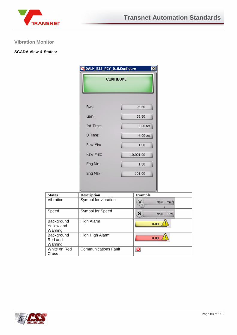
Transnet Automation Standards
Page 88 of 113
Vibration Monitor
SCADA View & States:
States Description Example
Vibration Symbol for vibration
Speed Symbol for Speed
Background Yellow and Warning
High Alarm
Background Red and Warning
High High Alarm
White on Red Cross
Communications Fault
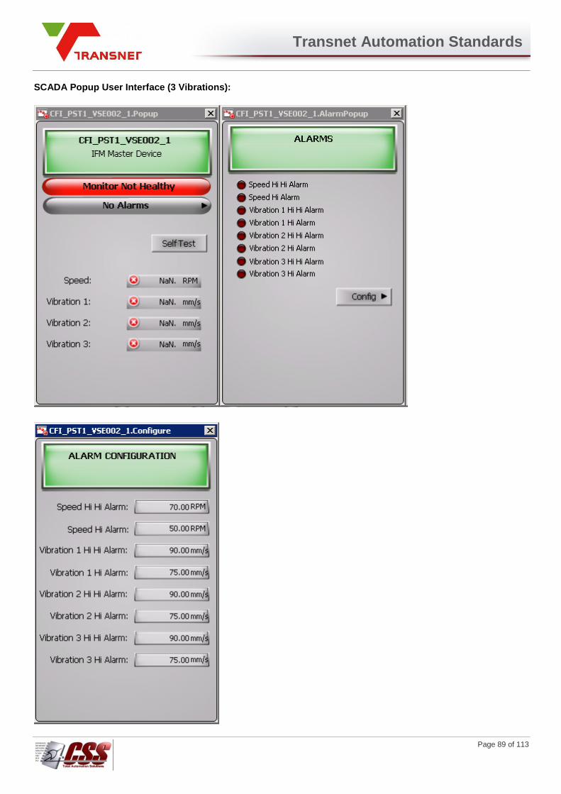
Transnet Automation Standards
Page 89 of 113
SCADA Popup User Interface (3 Vibrations):
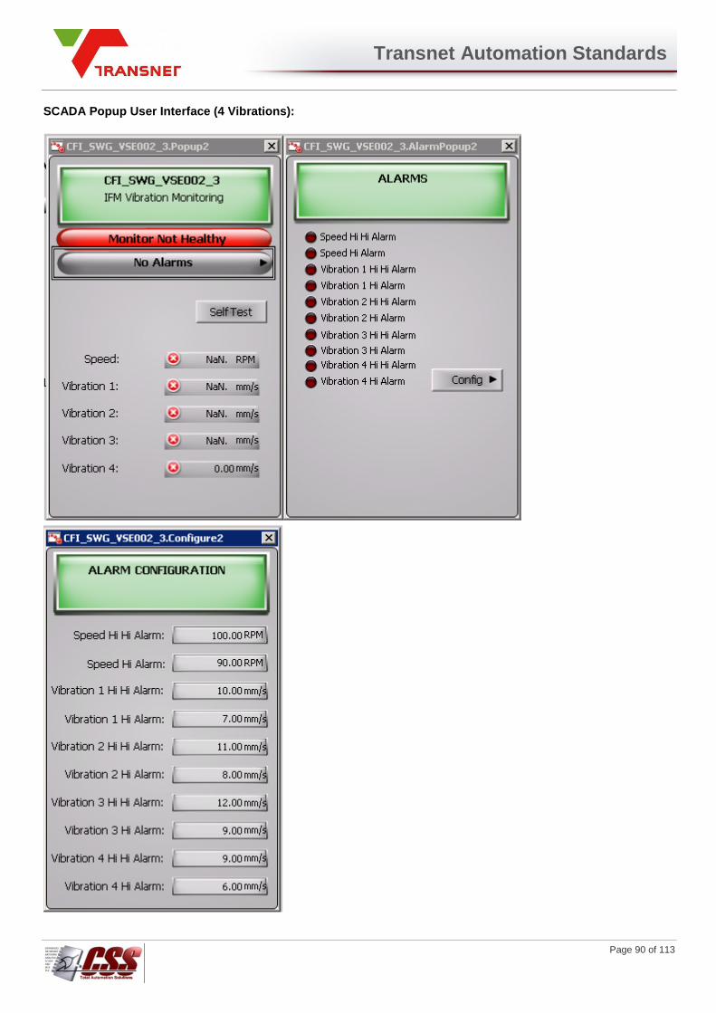
Transnet Automation Standards
Page 90 of 113
SCADA Popup User Interface (4 Vibrations):

Transnet Automation Standards
Page 91 of 113
Circuit Breaker
SCADA Relay View & States:
States Description Example
Relay This is the SCADA symbol for the protection relay of a circuit breaker displaying the name (e.g. “E09”)
Blue Skull is Visible
Permit Active on Circuit Breaker
Blue Skull is Visible
Remote Mode
Status Light is Green
Healthy, no Alarms
Status Light is flashing Blue/Red
Not Healthy
SCADA Circuit Breaker View & States:
States Example
Circuit Breaker open, source live and bus bar live
Circuit Breaker open, source dead and bus bar dead
Circuit Breaker open, source dead and bus bar live
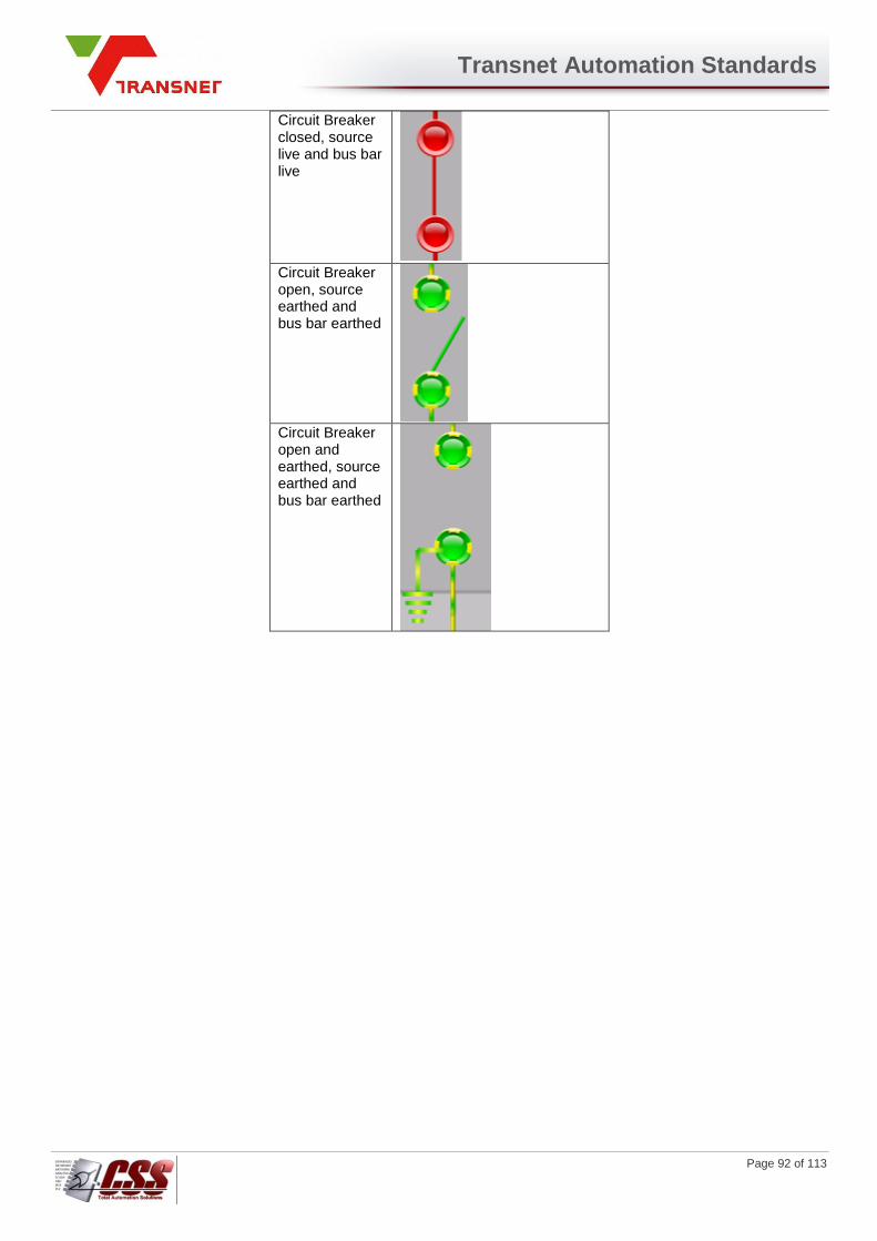
Transnet Automation Standards
Page 92 of 113
Circuit Breaker closed, source live and bus bar live
Circuit Breaker open, source earthed and bus bar earthed
Circuit Breaker open and earthed, source earthed and bus bar earthed
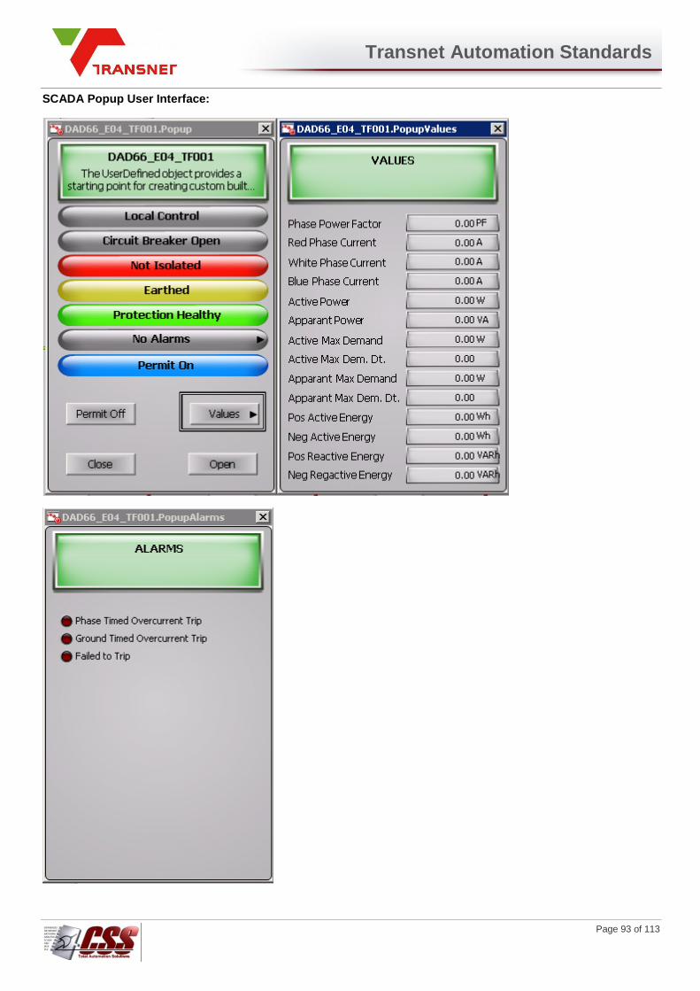
Transnet Automation Standards
Page 93 of 113
SCADA Popup User Interface:

Transnet Automation Standards
Page 94 of 113
Transformer
SCADA Relay View & States:
States Description Example
Relay This is the SCADA symbol for the protection relay of a circuit breaker displaying the name (e.g. “E09”)
Blue Skull is Visible
Permit Active on Circuit Breaker
Blue Skull is Visible
Remote Mode
Status Light is Green
Healthy, no Alarms
Status Light is flashing Blue/Red
Not Healthy
SCADA Transformer View & States:
States Example
Live current through transformer
No current through transformer (safe)
Transformer is earthed

Transnet Automation Standards
Page 95 of 113
SCADA Circuit Breaker View & States:
States Example
Circuit Breaker open, source live and bus bar live
Circuit Breaker open, source dead and bus bar dead
Circuit Breaker open, source dead and bus bar live
Circuit Breaker closed, source live and bus bar live
Circuit Breaker open, source earthed and bus bar earthed
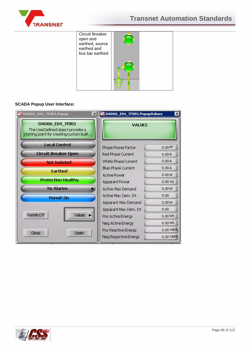
Transnet Automation Standards
Page 96 of 113
Circuit Breaker open and earthed, source earthed and bus bar earthed
SCADA Popup User Interface:
Transnet Automation Standards
Page 97 of 113
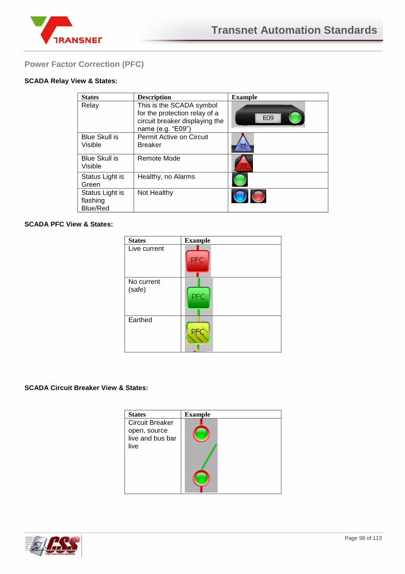
Transnet Automation Standards
Page 98 of 113
Power Factor Correction (PFC)
SCADA Relay View & States:
States Description Example
Relay This is the SCADA symbol for the protection relay of a circuit breaker displaying the name (e.g. “E09”)
Blue Skull is Visible
Permit Active on Circuit Breaker
Blue Skull is Visible
Remote Mode
Status Light is Green
Healthy, no Alarms
Status Light is flashing Blue/Red
Not Healthy
SCADA PFC View & States:
States Example
Live current
No current (safe)
Earthed
SCADA Circuit Breaker View & States:
States Example
Circuit Breaker open, source live and bus bar live

Transnet Automation Standards
Page 99 of 113
Circuit Breaker open, source dead and bus bar dead
Circuit Breaker open, source dead and bus bar live
Circuit Breaker closed, source live and bus bar live
Circuit Breaker open, source earthed and bus bar earthed
Circuit Breaker open and earthed, source earthed and bus bar earthed
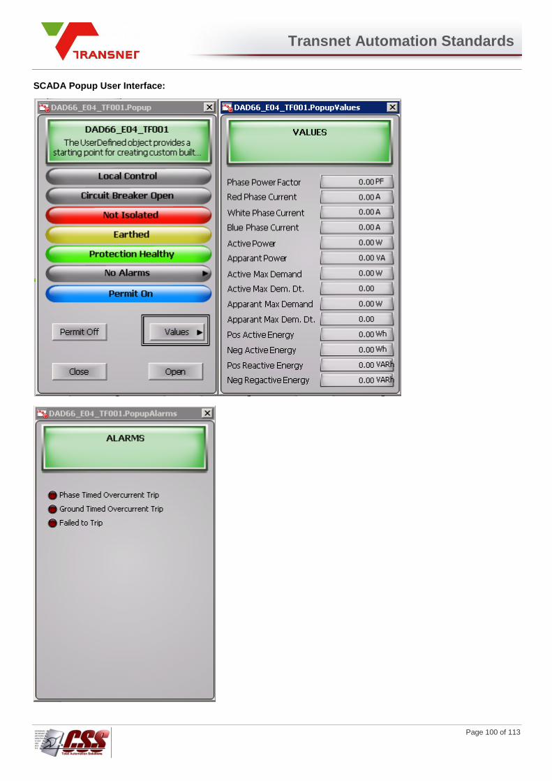
Transnet Automation Standards
Page 100 of 113
SCADA Popup User Interface:
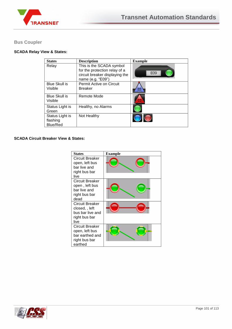
Transnet Automation Standards
Page 101 of 113
Bus Coupler
SCADA Relay View & States:
States Description Example
Relay This is the SCADA symbol for the protection relay of a circuit breaker displaying the name (e.g. “E09”)
Blue Skull is Visible
Permit Active on Circuit Breaker
Blue Skull is Visible
Remote Mode
Status Light is Green
Healthy, no Alarms
Status Light is flashing Blue/Red
Not Healthy
SCADA Circuit Breaker View & States:
States Example
Circuit Breaker open, left bus bar live and right bus bar live
Circuit Breaker open , left bus bar live and right bus bar dead
Circuit Breaker closed, , left bus bar live and right bus bar live
Circuit Breaker open, left bus bar earthed and right bus bar earthed
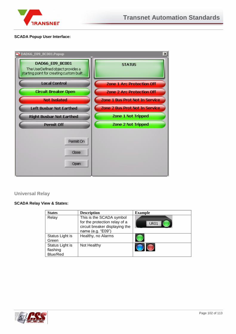
Transnet Automation Standards
Page 102 of 113
SCADA Popup User Interface:
Universal Relay
SCADA Relay View & States:
States Description Example
Relay This is the SCADA symbol for the protection relay of a circuit breaker displaying the name (e.g. “E09”)
Status Light is Green
Healthy, no Alarms
Status Light is flashing Blue/Red
Not Healthy

Transnet Automation Standards
Page 103 of 113
SCADA Popup User Interface:
Transnet Automation Standards
Page 104 of 113
PLC Watchdog ($PLCWatchdog)
Each PLC will run a one second timer continuously from 0 to 9999 seconds and transfer the accumulated value into a
nominated Watchdog register where the SCADA system can read its value. ArchestrA will be configured with a
Watchdog object for each PLC in the Galaxy. This object must continuously monitor the watchdog register with every
Analogue Topic scan. The PLC will be considered operational whenever the word content has changed from the
previous scan and a communication status attribute bit will be set to logic 1, indicating normal communication with the
PLC.
If no change was detected for 5 seconds or more, the communication status attribute bit will be set to logic 0, indicating a communication failure. Every InTouch graphic object related to the specific PLC will use this status bit to display a communication failure with a white flashing symbol.

Transnet Automation Standards
Page 105 of 113
INTER-SYSTEM COMMUNICATION
Communication between PLC's and Application Server
All communication between PLC’s and Level 2 Application Server’s shall be done exclusively over the Level 1
Ethernet Network. Each PLC shall be configured as a node on the network and shall be equally accessible by the
Level 2 Application Server. All required data from the PLC will be polled by the SCADA and no data transfers will be
initiated by the PLC. Data can be exchanged between Application Servers of different areas on the plant-wide data
network.
All data to be read by Level 2 will be located in addresses / memory areas in the PLC as specified in
the relevant PLC documentation.
A standard procedure will be implemented to document the data transferred between the PLC's and the Tag Server using a data exchange table (also called "data list"), documented using a CSV (Comma Separated Value) file. Any analogue value transmitted to the PLC's will be transmitted using the format defined by the Level 1 supplier (floating point, integer, timer, etc.).
SCADA - MES Communication
This section covers the data exchange between the SCADA and MES systems. The ArchestrA Application Server will archive data to the Historian Server database to provide for the MES system needs as well as its own historical trending display. MES data storage and retrieval will mainly be event driven by ArchestrA. Events will be configured in ArchestrA to trigger the required query/process/calculation of data at the time of the event and store the results in a level-2 interface table in the MSSQL database on the Historian Server. External processes will transfer the data in this table to the appropriate table in the MES database. Values can also be sent from the MES to the Level 1 equipment via ArchestrA by inserting data into an allocated table. A polling type object will be configured in ArchestrA to monitor the level-1 table in MSSQL for any new values to be written down to Level 1. External processes will populate the data in this table from the appropriate table in the MES database. The following flow diagram depicts the data flow between the SCADA and MES systems:
Figure 0-1: MES Data Flow Diagram
MSSQL
I/O Server
Industrial Application Server
Archestra Event handling Objects PLC
Historian Server
Historian Tables
MES Server
Data to / from MES (Site specific)
InTouch HMI

Transnet Automation Standards
Page 106 of 113
The external processes that transfer data between the SCADA and MES systems will be site specific, as specified by the MES Engineering Functional Specification for each site. Object templates with specific calculation functions will be defined in ArchestrA to be instantiated where required. Aggregate calculations (such as minimum, maximum, etc.) may be defined for tag information to be retrieved at specific intervals (such as the maximum value for a specific tag over a shift). Validation rules will be followed (where configured) to ensure that certain criteria are met before the information is used. The following Interval Types will be configured in ArchestrA:
Name Event Type
E On event
5m Every 5 minutes
10m Every 10 minutes
1h Every 1 hour
S Every Shift end
Table 0-1: Event Types
The MES system will read data directly from the MSSQL Server level 2 interface tables and write return values in the level 1 interface table. This data will be processed and written into the MES Oracle database for long-term storage and reporting. The detailed definition of the data calculation types, events, storage and SQL data transfer, specific for each area, will be described in the document specifying the SCADA Functional Analysis for that area as well as the MES specification for each area.
Watchdog Procedure
In order to ensure a high level of confidence and efficiency as well as process security, each device involved in a communication link will verify that the other devices are operational. A standard watchdog routine will be applied between:
1. PLC's and ArchestrA,
2. The MES Server and the level 2 interface MSSQL Server. PLC and ArchestrA Watchdog Each PLC will run a one second timer continuously from 0 to 9999 seconds and transfer the accumulated value into a pre-defined watchdog register. ArchestrA will continuously monitor this register. The PLC will be considered operational whenever the word content has been changed. A communication failure fault will be announced if no change was detected for 5 seconds and all HMI graphic objects related to the specific PLC will be displayed white flashing to indicate a communication failure. MES Server and Historian Watchdog The MES Server will continuously monitor the system seconds variable of the Historian Server for a change in value. The MES Server will take the appropriate action if there is no change for longer than 5 seconds. This action will be defined in the MES Functional Analysis document.
Clock Synchronisation
Every computer participating in the Galaxy must be configured to synchronize its clock to a site Network Time Protocol (NTP) Server or equivalent system. If such a server is not available then all the computers should synchronize their clocks with the Historian Server. This is mandatory for a Galaxy to ensure that all data is in sync.
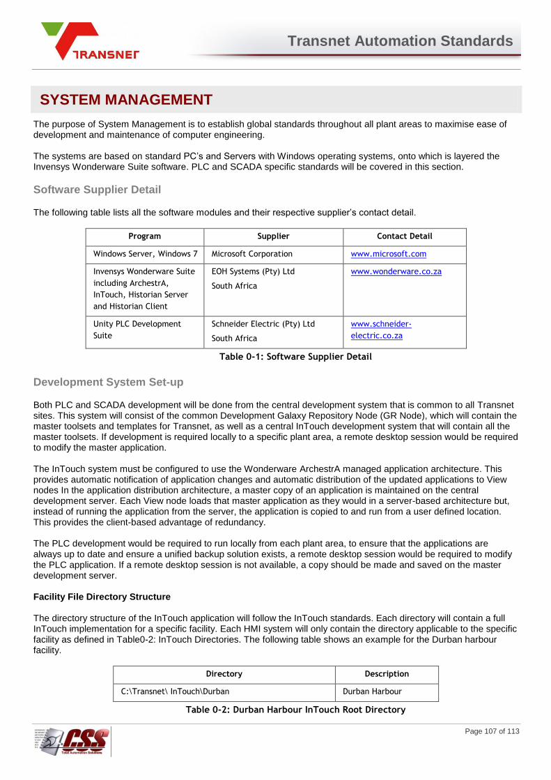
Transnet Automation Standards
Page 107 of 113
SYSTEM MANAGEMENT
The purpose of System Management is to establish global standards throughout all plant areas to maximise ease of development and maintenance of computer engineering. The systems are based on standard PC’s and Servers with Windows operating systems, onto which is layered the Invensys Wonderware Suite software. PLC and SCADA specific standards will be covered in this section.
Software Supplier Detail
The following table lists all the software modules and their respective supplier’s contact detail.
Program Supplier Contact Detail
Windows Server, Windows 7 Microsoft Corporation www.microsoft.com
Invensys Wonderware Suite
including ArchestrA,
InTouch, Historian Server
and Historian Client
EOH Systems (Pty) Ltd
South Africa
www.wonderware.co.za
Unity PLC Development
Suite
Schneider Electric (Pty) Ltd
South Africa
www.schneider-
electric.co.za
Table 0-1: Software Supplier Detail
Development System Set-up
Both PLC and SCADA development will be done from the central development system that is common to all Transnet sites. This system will consist of the common Development Galaxy Repository Node (GR Node), which will contain the master toolsets and templates for Transnet, as well as a central InTouch development system that will contain all the master toolsets. If development is required locally to a specific plant area, a remote desktop session would be required to modify the master application. The InTouch system must be configured to use the Wonderware ArchestrA managed application architecture. This provides automatic notification of application changes and automatic distribution of the updated applications to View nodes In the application distribution architecture, a master copy of an application is maintained on the central development server. Each View node loads that master application as they would in a server-based architecture but, instead of running the application from the server, the application is copied to and run from a user defined location. This provides the client-based advantage of redundancy. The PLC development would be required to run locally from each plant area, to ensure that the applications are always up to date and ensure a unified backup solution exists, a remote desktop session would be required to modify the PLC application. If a remote desktop session is not available, a copy should be made and saved on the master development server. Facility File Directory Structure The directory structure of the InTouch application will follow the InTouch standards. Each directory will contain a full InTouch implementation for a specific facility. Each HMI system will only contain the directory applicable to the specific facility as defined in Table0-2: InTouch Directories. The following table shows an example for the Durban harbour facility.
Directory Description
C:\Transnet\ InTouch\Durban Durban Harbour
Table 0-2: Durban Harbour InTouch Root Directory
Transnet Automation Standards
Page 108 of 113
Backup Procedure
Application Backup Two separate backups need to be done for the ArchestrA Galaxy Repository and the InTouch application. A complete backup, including the InTouch Symbol Directory, should be completed after any configuration changes. This backup must follow the standard backup destination and standards set by the system administrator for any other Windows application. The Galaxy backup can be scheduled to run automatically using a Wonderware supplied utility. During the development phase, the application programmer must perform such a backup regularly so as to enable him to easily restore an application whenever required. During start-up and commissioning, such a backup should be taken from the production system prior to implementing any new version of the application.
Historian Backup
The Historian Server must be configured to do a daily automatic scheduled backup of the real time data files in the Historian Data directory. A complete system backup, including the MSSQL database, should be completed after any configuration changes.
Change Management
A software package to provide and maintain a constant level of revision control for both PLC and SCADA programming software, like MASS AutoSave, should be utilised as part of development governance.
System Error Handling
All system errors will be logged by Windows and can be viewed using the Event Viewer utility. The ArchestrA Logger program logs all Invensys Wonderware suite program errors and events, which can be viewed using the System Management Console (SMC) installed as part of ArchestrA.
Production System Set-up
There will be five types of production computers, an Application Server, an HMI workstation and a Historian Server with the following configuration:
1. Galaxy Repository server, which will host the ArchestrA development objects and contain deployment
logic. This server will also contain revision control software and will be considered as the main engineering
development station.
2. Industrial Application Server (called AppServer), which will be configured to run deployed ArchestrA
objects. There will be two similar AppServers, running in dual redundant mode, and called Primary and
Secondary AppServer. Both servers running the same software and communicating with the PLC’s in
parallel will achieve redundancy between the two. Their function is mainly to supply real time data from the
PLC’s to the HMI’s, the Historian database and the MES, as well as any other client software (like Excel)
requesting data.
3. Historian Server, which will be configured to run IndustrialSQL Server as well as the Alarm DB Logger
manager. There will be one historian server per area, shared by all the plants for that area.
4. Information Server, which will host all HTML reporting information. The information available from the
information server will be collected from the Historian server mentioned above.
5. HMI Terminals, which will be configured to run InTouch WindowViewer acting as view client for ArchestrA.
Real time data will be acquired from ArchestrA objects running on the AppServer machine. Multiple HMI’s
per plant will be configured identical to run in parallel to each other. All data required by InTouch will
automatically be obtained from the active App Server only. See the next Section for configuration detail.

Transnet Automation Standards
Page 109 of 113
Network Node Name Configuration
The network node names must be defined as per the site-specific standards.
Application Data Server
The following software must be installed and configured on every AppServer.
i) Windows Server,
ii) Industrial Application Server (IAS) Bootstrap,
iii) A deployed WinPlatform,
iv) A deployed AppEngines.
HMI Terminal The following software must be installed and configured on every HMI PC.
i) Windows 7 Professional,
ii) InTouch WindowViewer
Historian Server The following two points should be observed while installing Historian:
The History Data Destination Path should point to X:\Historian\Data (where X is the
designated data drive).
The Historian Database size must always be selected as Large.
The following software must be installed and configured on every Historian Server.
i) Microsoft Windows Server,
ii) Microsoft SQL Server,
iii) Historian Server with all its components.
InTouch System Configuration Set-up
The InTouch system should be configured along the following guidelines:
1) Configure VGA display driver,
2) Customise colour palette,
3) Install Wizards,
4) Configure View Generic,
5) Configure WindowViewer,
6) Define Home Windows,
7) Define Global system Scripts.
Configure VGA Display Driver
The VGA display driver on an HMI should be configured to display 1920×1080p dpi, High Colour (32 bit) or better, Small Fonts and a horizontal frequency of 85 Hz. The VGA display driver for an AppServer should be set at 1024 x 768 dpi, High Colour, Small Fonts and a horizontal frequency of 75 Hz.

Transnet Automation Standards
Page 110 of 113
Customise Colour Palette The InTouch colour palette should be customised as indicated in earlier section Set-up users Under ArchestrA Security The different level of users with appropriate names and passwords should be configured as described in earlier Section. Configure WindowViewer General The following figure shows the settings for the View Generic Configuration.
Figure 0-1: View Generic Configuration
WindowViewer Window Configuration
The EnableDisablekeys function combined with the following WindowViewer configuration settings and the Start-up Scripts will ensure that the operator cannot get into the operating system. The following figure shows the Configuration settings for the WindowViewer.

Transnet Automation Standards
Page 111 of 113
Figure 0-2: WindowViewer Configuration
Define Home Windows The Home windows are the InTouch windows that will be displayed when WindowViewer is started. The Banner screen must always be included as a home window. The second home window is the main Navigation window. The third home window is the Overview graphic screen. This window will show an overview graphic for the whole section of the specific area or plant. It is also the window that will be displayed when the Overview button is selected on the main banner. These windows must be selected from the InTouch Special Configure – WindowViewer, Home Windows set-up dialog. Define Global System Scripts The following Application, Condition and Data Change Scripts should be defined in InTouch. Scripts should be defined for each application as required, but should be kept to a minimum and must only be used when no other standard InTouch function is available.
Application Scripts
1. On Startup:
DIM ThisNodeName AS MESSAGE; GetNodeName( ThisNodeName, 31 ); LogMessage(ThisNodeName); IF ThisNodeName == XXXXX THEN USER_AREA_NODE_EDIT_ALLOWED = 1; ELSE USER_AREA_NODE_EDIT_ALLOWED = 0; ENDIF;
The Startup script checks to see if the Electrical Switching Security System can be edited from this InTouch View Node. The Startup script disables the Windows AltKey, EscKey and WinKey functions and disables the Windows Reboot and Taskswitch functions. The manual mode is set to ‘none’ and the Supervisory flag is set to true if the local node is a supervisory node, else the manual mode is set to ‘operator’ and the Supervisory flag is set to false for HMI use.
Transnet Automation Standards
Page 112 of 113
2. On Shutdown: EnableDisableKeys(1,1,1);
This Shutdown script enables the Windows AltKey, EscKey and WinKey functions and enables the Windows Reboot and Taskswitch functions.
Condition Scripts
1. {Admin security cntr} $AccessLevel > 9000 Condition Type: On False {Administrator/Automation logged off - switch on traps} EnableDisableKeys(0,0,0);
This script enables the keytrap function and disables the Windows AltKey, EscKey, WinKey, Reboot and Taskswitch functions when the logged on user is not the administrator or automation. Condition Type: On True {Administrator/Automation logged on - switch off traps} EnableDisableKeys(1,1,1); This script disables the keytrap function and enables the Windows AltKey, EscKey, WinKey, Reboot and Taskswitch functions when the logged on user is the administrator or automation. 2. CloseApp This script closes the InTouch View Application 3. LogOffInTouch This script logs the current user off. 4. LogOnInTouch This script opens the log on dialog. 5. The rest of the Condition Scripts make up the management of the Electrical Switching Security System. The editing of certain of these scripts is discussed in Electrical Switching Security System.
Data Change Scripts
Add a data change script to InTouch that will execute any time the InTouch system tag $Operator changes. The script will initialize a check with the Electrical Switching Security System to determine what if any rights the current user has to electrical switching.
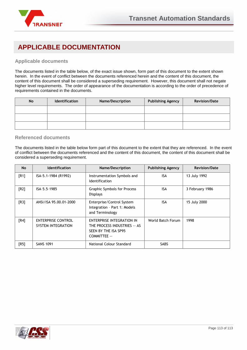
Transnet Automation Standards
Page 113 of 113
APPLICABLE DOCUMENTATION
Applicable documents
The documents listed in the table below, of the exact issue shown, form part of this document to the extent shown herein. In the event of conflict between the documents referenced herein and the content of this document, the content of this document shall be considered a superseding requirement. However, this document shall not negate higher level requirements. The order of appearance of the documentation is according to the order of precedence of requirements contained in the documents.
No Identification Name/Description Publishing Agency Revision/Date
Referenced documents
The documents listed in the table below form part of this document to the extent that they are referenced. In the event of conflict between the documents referenced and the content of this document, the content of this document shall be considered a superseding requirement.
No Identification Name/Description Publishing Agency Revision/Date
[R1] ISA-5.1-1984 (R1992) Instrumentation Symbols and
Identification
ISA 13 July 1992
[R2] ISA–5.5–1985 Graphic Symbols for Process
Displays
ISA 3 February 1986
[R3] ANSI/ISA 95.00.01-2000 Enterprise/Control System
Integration – Part 1: Models
and Terminology
ISA 15 July 2000
[R4] ENTERPRISE CONTROL
SYSTEM INTEGRATION
ENTERPRISE INTEGRATION IN
THE PROCESS INDUSTRIES -- AS
SEEN BY THE ISA SP95
COMMITTEE --
World Batch Forum 1998
[R5] SANS 1091 National Colour Standard SABS


![TRANSNET PORT TERMINALS Notices... · TRANSNET PORT TERMINALS An Operating Division of TRANSNET SOC LTD [Hereinafter referred to as Transnet] Registration Number 1990/000900/30 REQUEST](https://static.fdocuments.in/doc/165x107/600560c52af56b6cdb7b80d6/transnet-port-notices-transnet-port-terminals-an-operating-division-of-transnet.jpg)

