AUTOMATIC LEVEL MANUAL - 2helpU · Automatic Level Maintenance Manual ... CST/Berger 2001. SAL...
26
SAL 20/24/28/32 PAGE 1 REV. C 071803 Automatic Level Maintenance Manual SAL-XX W/ AIR DAMPENED COMPENSATOR CST/Berger 2001
Transcript of AUTOMATIC LEVEL MANUAL - 2helpU · Automatic Level Maintenance Manual ... CST/Berger 2001. SAL...

SAL 20/24/28/32 PAGE 1 REV. C 071803
Automatic LevelMaintenance Manual
SAL-XX W/ AIR DAMPENED COMPENSATOR
CST/Berger2001
SAL 20/24/28/32 PAGE 2 REV. C 071803
Automatic LevelMaintenance ManualUser Calibration and Testing.................. 3Circular Vial............................................ 3Collimator Calibration............................. 3Field Calibration..................................... 4Maintenance Charts............................... 5Repair Procedures.................................. 12Replacing Spindle................................... 12Replacing Bubble Level.......................... 13Replacing Level Screws......................... 13Replacing Endless Horizontal Drive......... 15Replacing Objective Lens and FocusingSystem.................................................... 16Replacing Focusing Knob Assembly....... 17Replacing Reticle and Eyepiece.............. 18Replacing Compensator.......................... 19Detailed Parts Listing ............................... 20
MANUAL
INDEX

SAL 20/24/28/32 PAGE 3 REV. C 071803
User Calibration and TestingAll CST/berger automatic levels have undergone testing before their sale; however,some changes in bubbles or zero positions may occur due to rough handling duringtransport or other reasons. Testing and any adjustments should be made beforeusing the level.
Testing the circular bubble1. Attach auto level to tripod with tripod fastening screw. Turn level screws to
center the bubble. 2. Move telescope 180 degrees and see if bubble is in the center position (A).Ifnot, an adjustment is necessary (B).3. Turn level screw to move bubble to correct the error (halfway to center) (C).4. Adjust bubble screw with hex key wrench (located in carrying case) to move
bubble the rest of the way back to center (D).5. Repeat steps 2, 3, and 4 until the bubble stays centered.
Collimator Calibration1. Attach auto level onto the collimator stand. Center circular bubble.2. Aim the level at collimator to see if horizontal hairs of the level and of the
collimator overlap.

SAL 20/24/28/32 PAGE 4 REV. C 071803
3. If there is no overlap, take off cover around eyepiece and adjust screw locatedon upper part of reticule with adjusting pin (located in carrying case)(E) untilhorizontal hairs overlap.
Field Calibration1. Set level between two staffs as shown in figure F. Level the instrument,reading staff a and b at a1 and b1; the difference in height between staffs a andb is: Îh=a1-b1.2. Move the level 1-2 meters away from staff a. Level the instrument, readingstaff a and staff b at a2 and b2. If a2-b2=a1-b1=Îh, the sight line is horizontal.3. If the sight line is not horizontal, take the value of Îh as a basis for correcting
zero position and correcting the value of h=a2-b2 (G). Aiming at staff b, takeoff the cover around the eyepiece and adjust the screw (E) on the upper part ofreticle with adjusting pin (located in carrying case) until the difference (Îh) isequal to the value of Îh in step 1. 4. Repeat steps 1, 2, and 3 until (a1-b1)=(a2-b2).

SAL 20/24/28/32 PAGE 5 REV. C 071803

SAL 20/24/28/32 PAGE 6 REV. C 071803
SAL 20/24/28/32 PAGE 7 REV. C 071803
SAL 20/24/28/32 PAGE 8 REV. C 071803
SAL 20/24/28/32 PAGE 9 REV. C 071803

SAL 20/24/28/32 PAGE 10 REV. C 071803

SAL 20/24/28/32 PAGE 11 REV. C 071803

SAL 20/24/28/32 PAGE 12 REV. C 071803
SAL 20/24/28/32 PAGE 13 REV. C 071803
Repair Procedures
Replacement of SpindleRefer to parts 55-70355 (inner and outer spindle set) in diagramH.
Dismantling1. Remove snap ring for inner spindle 55-70362 (diagram H) with bent-tip snapring pliers; take telescope 55-70353 from base by pulling gently and rotating.2. Remove screws 55-70354 (4 screws) with Phillips-head screwdriver; remove
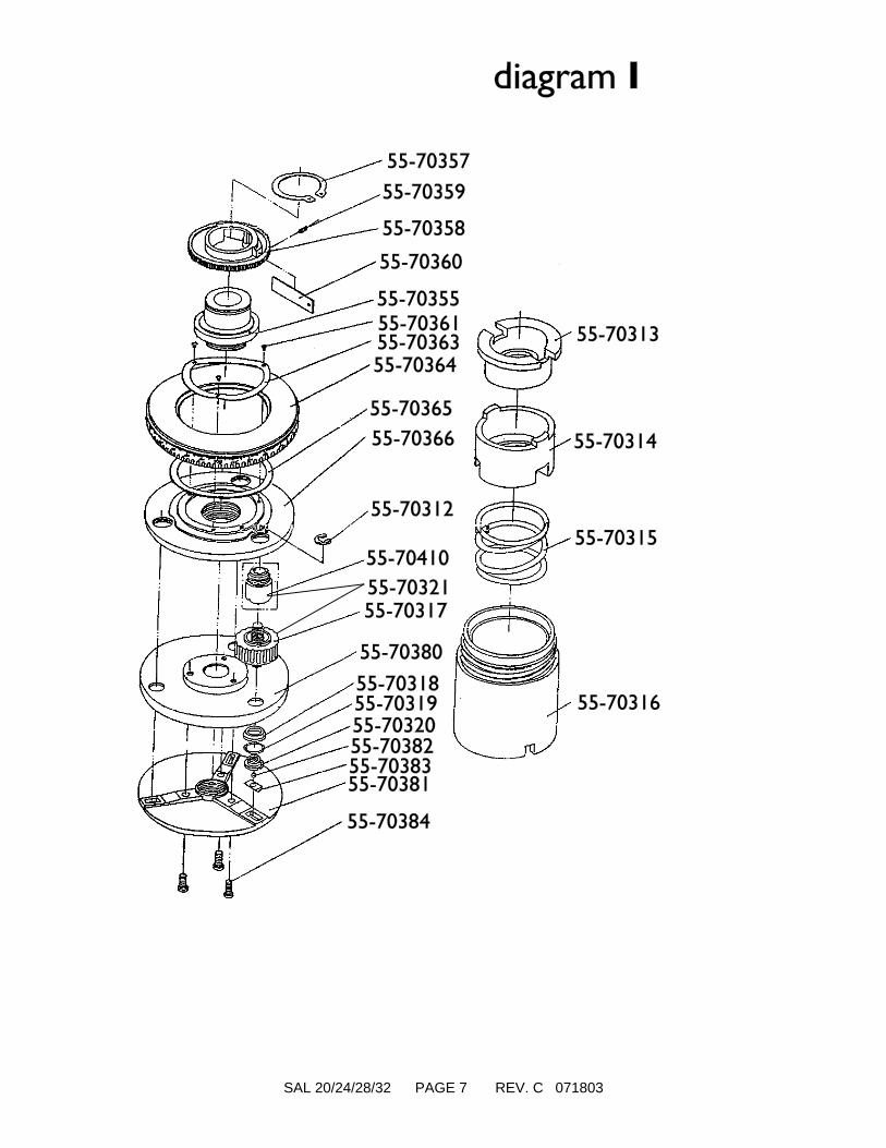
inner spindle.3. Remove snap ring 55-70357 (diagram I) with snap ring pliers; remove gear
55-70359 and spring 55-70360.4. Remove screws 55-70361 (3 screws) with Phillips-head screwdriver; remove
retaining ring 55-70363, circle 55-70364, and friction washer 55-70365.5. Heat outer spindle 55-70355 on electric stove (with upper end in contact with
stove); heat no higher than 80EC (112EF). Turn outer spindlecounterclock-wise off base 55-70366 with spanner wrench going through two(2) holes.
AssemblingCheck parts, and replace those that are worn out. Assemble inreverse order of diagrams H and I with attention to the following:1. Before assembling outer spindle 55-70355, some thread locking adhesiveshould be applied to the threads; then screw outer spindle 55-70355 intoconnecting base 55-70366. Make sure the end of the spindle is tight against theconnecting base.2. Apply specialized lubricating grease underneath end of retaining ring 55-70363.3. After tightening screws 55-70361, check if circle 55-70364 turns easily. Fixand seal screws 55-70361 with anaerobic glue (the glue should not touch any
painted surfaces or plastic parts).4. Before assembling gear 55-70358, specialized lubricating grease should be
applied to the outer surface of the spindle that touches gear.

SAL 20/24/28/32 PAGE 14 REV. C 071803
5. Gear 55-70358 should be stable and moveable around spindle. Adjust screw55-70359 to generate proper tension on the gear rotating around the spindle.
6. Clean the surfaces of the spindle; apply grease specialized for these surfaces.
7. Referring to diagram H, onto base place Teflon bearing disc 55-70356, thentelescope body 55-70353. Then install snap ring 55-70362 into the groove ofthe inner spindle 55-70362.
8. After assembly, refer to page 2 to test and readjust the circular bubble.
Replacement of Circular VialSee diagram H.
Dismantling1. Remove snap ring on bottom of inner spindle 55-70362 with bent-tip snap ring
pliers. Turn telescope body while pulling gently until it is off the base.2. Remove screws 55-70388 (2 on upper side) and 55-70497 (1 underneath) with
hex key wrench (located in carrying case). Remove circular vial 55-70389 andrubber gasket 55-70387 around it.
AssemblingAfter replacing the bubble level, assemble in reverse order ofdiagram H with attention to the following:1. When attaching bubble level 55-70389 onto telescope body 55-70353, tightenthe
55-70497 screw then evenly tighten the other (2) of screws 55-70388. Do notovertighten. Connect telescope to base. Refer to page 2 to test and readjust
thecircular bubble.
2. If the bubble is out of adjustment, screws 55-70388 must be tightened orloosened as necessary to center the bubble. (Do not over-tighten)
3. Assemble other parts by referring to diagram H. Apply axis grease to theouter circle-shaped surface of the spindle.

SAL 20/24/28/32 PAGE 15 REV. C 071803
Replacement of Level ScrewsSee diagram I, parts 55-70410 and 55-70317.
Dismantling1. Remove snap ring 55-70362 for spindle (see diagram H & I) with bent-tipsnap ring pliers. Turn telescope body 55-70353 while gently pulling and removefrom base.2. Referring to diagram I, remove snap ring for spindle 55-70357 with snapring pliers. Remove gear 55-70358 and spring 55-70360.3. Remove screws 55-70361 (3 screws) with Phillips-head screwdriver. Takeoff retaining ring 55-70363, circle 55-70364, and friction ring 55-70365.
4. Remove "E" clip 55-70312.5. Remove screws 55-70384 (3 screws) with hex key wrench. Take off base
55-70381, bearing seat 55-70383, and steel ball 55-70382.6. Turn spanner nut 55-70320 (3 ea.) counterclockwise with special spanner.Take off Teflon washer 55-70319, tension ring 55-70318, and base cover 55-70380.7. Remove level screw 55-70317.8. Remove level screw bushing assembly 55-70410 with special tool.
NOTE: There is no need to remove it if it isn't damaged. If replacement isnecessary, heat it over an electric stove no hotter than 80EC (112EF), then
turn it counterclockwise off of connecting base.
AssemblingCheck parts, and replace those that are worn out. Assemble inreverse order of diagram I with attention to the following:1. Before attaching level screw bushing assembly 55-70410, apply epoxy to three
screw holes of M16X1 in connecting base 55-70366; then screw in and tightenlevel screw nuts.
2. Before attaching level screw 55-70317, apply grease to the threads M7X0.75,then screw into level screw bushing assembly 55-70410.
3. After tightening spanner nut 55-70320 onto level screw 55-70317, fix and sealit with anaerobic glue (glue should not touch painted surfaces and plastic parts).4. Apply special grease to friction face of bearing seat 55-70383 touching base
55-70381 and the one touching steel ball 55-70382.
SAL 20/24/28/32 PAGE 16 REV. C 071803
5. Even tightening of screws 55-70384 is necessary for appropriate tension andsecuring of footplate 55-70381.
6. After tightening screws 55-70384, rotate thread tensioning ring 55-70313 inlevel screw bushing assembly 55-70410. Turn one revolution clockwise tosecure level screw 55-70317 and assure appropriate dynamics. After propertension is achieved, seal thread tensioning ring and level screw cover withanaerobic glue.
7. Apply special grease underneath circle 55-70364 and retaining ring 55-70363.8. After tightening screws 55-70361, check to see if circle 55-70364 rotatesfreely. Seal screws 55-70361 with anaerobic glue.9. Before installing gear 55-70358, apply special grease to all surfaces of outerspindle 55-70355 that contact with gear 55-70358.10. Gear 55-70358 should rotate smoothly around outer spindle 55-70355.
Turn screw 55-70359 in diagram I to adjust the amount to tension on themovement of the gear.11. After cleaning up the surfaces of inner and outer spindle 55-70355, put some
drops of special spindle grease onto all contacting surfaces.12. Referring to diagram H, onto base attach washer 55-70356, then telescope
body 55-70353. Then put snap ring 55-70362 into the groove of inner spindle55-70355.
Replacement of Endless Horizontal DriveSee diagrams H, I, and J.
Dismantling1. Referring to diagram H, remove snap ring 55-70362 with bent-tip snap ring
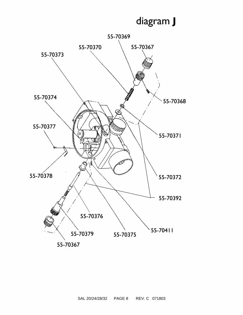
pliers. Turn telescope body 55-70353 while pulling gently until it is off base.2. Referring to diagram J, take off cover 55-70367 around the knob.3. Loosen left tangent knob set screw 55-70368 with flat-head screwdriver. Take care when loosening the screws; when released, spring 55-70370 will pushknob 55-70369 off quickly towards you. Then take off the spring 55-70370,spacer 55-70371, and friction washer 55-70372.4. Loosen set screw 55-70411 and remove horizontal tangent screw 55-70376,drive bushing 55-70375, and spacer 55-70374.5. Referring to diagram I, remove snap ring 55-70357 with snap ring pliers. Take

SAL 20/24/28/32 PAGE 17 REV. C 071803
off gear 55-70358 and friction plate 55-70360 if necessary.
AssemblingCheck parts, and replace those that are worn out. Refer todiagram I and assemble in reverse order of diagram J withattention to the following:1. Assemble horizontal tangent screw shaft 55-70376 and relevant partsaccording to diagram J, and check if leaf spring 55-70378 has proper tension toengage horizontal worm drive 55-70379 into gear 55-70358 when assembled.
2. Before attaching gear 55-70358, apply special grease to the outer circle-shapedface (coordinating with gear) of outer spindle 55-70355 (see diagram I).
3. Gear 55-70358 should revolve smoothly around spindle 55-70355. Adjustscrew 55-70359 in diagram I to increase or decrease tension on the movementof the gear revolving around the spindle.4. Apply special grease to the connecting part of gear 55-70358 and horizontal
tangent screw shaft 55-70376.5. After cleaning up the mating surfaces of inner and outer spindle 55-70355 (see
diagram H), put some drops of special axis grease onto the outer face.
6. Referring to diagram H, onto base place Teflon bearing disc 55-70356, thentelescope body 55-70353. Then install snap ring 55-70362 into the groove ofinner spindle 55-70355.
7. Adjust screw 55-70411 in diagram J to be about 0.4mm away from drivebushing 55-70375. Seal the screw with paint.
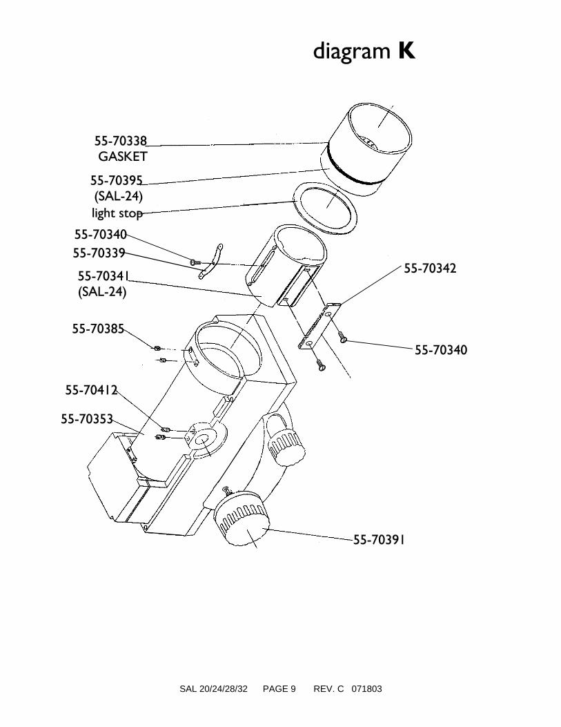
Replacement of Objective Lens, FocusingSystemCheck parts, and replace those that are worn out. Assemble inreverse order of diagram K with attention to the following:Dismantling1. Remove screws 55-70336 (4 screws - diagram H) with Phillips-head
screwdriver and take off the cover of telescope body 55-70353.
SAL 20/24/28/32 PAGE 18 REV. C 071803
2. Before removing objective lens assembly 55-70395 (diagram K), pencil markthe position of the lens to make it easy to reassemble.3. Loosen set screw 55-70385 (2 screws) with flat-head screwdriver; remove
objective lens assembly 55-70395.4. Before removing the focusing assembly 55-70391, turn the focus knobclockwise
(toward infinity) until it hits the stop. Remove set screw 55-70412 (2) with aflat- head screwdriver: remove focusing assembly 55-70391. The white pinion guide55- 70335 might remain in the telescope body 55-70353; remove it with a pair of
tweezers. 5. Before removing the focusing slide 55-70341, pencil mark its position relativeto the telescope body 55-70353. Take out focusing slide 55-70341, and checkfocusing rack 55-70342 to see if it needs to be replaced.
AssemblingCheck parts, and replace those that are worn out. Assemble inreverse order of diagram K with attention to the following:1. Put the pinion guide 55-70335 back into the end of the focusing assembly
55-70391. Slide the focusing slide 55-70396 into the telescope body 55-70353and position per pencil mark (drawn during dismantling). Insert focusing
assembly 55-70391 using extreme care not to bend the pinion guide 55-70335.(It might be helpful to look in the objective end of the telescope housing whileinserting the focusing assembly 55-70391 into the focus slide 55-70341 to insureproper alignment.) Tighten set screw 55-70412 (2). Once tightened, check theinstallation by turning the focus knob all the way in both directions. The focuspinion should stay engaged with the focus slide.
2. When replacing rack 55-70342, remove screw 55-70340 (2).3. Glue light stop to the telescope body 55-70353 with neutral epoxy (remove
existing glue first).4. Replace gasket 55-70338 as necessary. Align objective lens assembly 55-70338with pencil marks (drawn during dismantling) to ensure an accurate positioning.5. Seal screw 55-70412 and 55-70385 with paint after tightening.6. After assembly, refer to page 2 to test and re-calibrate.

SAL 20/24/28/32 PAGE 19 REV. C 071803
Replacement of Focusing Knob AssemblyCheck parts, and replace those that are worn out. Assemble inreverse order of diagram L with attention to the following:Dismantling 1. Take off rubber cover 55-70322.2. Remove screw 55-70324 with Phillips-head screwdriver. Dismantle the partsin the order indicated in diagram L. NOTE: If stop ring 55-70328 is undamaged,
there is no need to separate.
AssemblingCheck parts, and replace those that are worn out. Assemble inreverse order of diagram L with attention to the following:1. After tightening screw 55-70324, seal it with paint.
Replacement of Reticle and EyepieceCheck parts, and replace those that are worn out. Assemble inreverse order of diagram M with attention to the following:Dismantling1. Rotate cover 55-70306 counterclockwise and remove.2. Remove screws 55-70304 (3 screws) with flat-head screwdriver; take off
eyepiece knob 55-70305.3. Remove screws 55-70307 (4 screws) with Phillips-head screwdriver; remove
eyepiece housing 55-70308 (within which there is the eyepiece lenses) andgasket 55-70309.
4. Remove screws 55-70413 (4 screws) with Phillips-head screwdriver; take offreticle housing 55-70302 (with it will come 1 ea.: reticle unit 55-70310, reticleadjusting screw 55-70303, spring button 55-70311, and leaf spring (55-70352)and gasket 55-70309.) NOTE: If the parts in reticle housing 55-70302 need
to be replaced, or reticle unit 55-70310 needs to be cleaned, remove screws55-70307 (4 screws); otherwise, there is no reason to dismantle them. Keep theseparts, especially reticle unit 55-70310, free from dust. They are only to becleaned by professionals.
SAL 20/24/28/32 PAGE 20 REV. C 071803
AssemblingCheck parts, and replace those that are worn out. Assemble inreverse order of diagram M and readjust according to thefollowing steps:1. Attach the level onto the collimator and level circular bubble.2. Fit into reticle housing 55-70302, the leaf spring 55-70352, reticle piston55-70311, reticle unit 55-70310, and adjusting screw 55-70303.3. Connect gasket 55-70351 and assembled reticle housing 55-70302 totelescope body with screws 55-70413.4. Connect gasket 55-70309 and eyepiece assembly 55-70308 to telescope bodywith screws 55-70307.5. Direct the level towards collimator. Observe to see if the horizontal hairs ofthe level and of the collimator overlap. If not, then adjust screw 55-70303 untilthey overlap and are perpendicular.5. If they are not perpendicular, loosen screws 55-70413 (4 screws), and turn the
reticle housing in the appropriate direction until the hair in the level no longertilts against the hair in the collimator. Then fasten and seal screws 55-70413 with
paint.6. Assemble the remaining parts, then test and adjust.
Replacement of CompensatorThis work should be done by an experienced professional.
Dismantling1. Attach the level onto the collimator and level circular bubble.2. Remove screws 55-70336 (4 screws as shown in diagram H) with
Phillips-head screwdriver; take off the cover of telescope body55-70344.3. Referring to diagram O, remove screws 55-70348 (4 screws); take off
compensator cover 55-70349 and gasket 55-70350.4. Remove screws 55-70300 (2 screws) with Phillips-head screwdriver. Take out
compensator 55-70301. NOTE: Keep the dismantled parts and the inner partof the level clean.
SAL 20/24/28/32 PAGE 21 REV. C 071803
AssemblingCheck parts, and replace those that are worn out. Assemble inreverse order of diagram N with attention to the following:1. Lightly fasten compensator 55-70301 with two screws 55-70300 as indicatedin diagram O.2. Tilt the level forward or backward approximately +/-10' to see if there is any
change in the position of the level's crosshair with that of the collimator. Ifthere is a change move forward or backward the entire compensator until nochange in the crosshairs occurs when tilting the level. 3. Tilt the level left or right approximately +/-10' to see if there is any change in
the horizontal position of the level's hair with that of the collimator. If thereis a change, loosen screws 55-70300, and turn clockwise or counterclockwise the
entire compensator until no change in the horizontal position occurs whenturning the level. Tighten screws 55-70300. Repeat steps 2 and 3 until
compensating accuracy and cross accuracy are perfect. NOTE:Compensating accuracy and cross accuracy interact, so consideration should begiven to both of them when testing and adjusting; i.e. carry out simultaneousadjustment of the two accuracies, meaning a compound side to side tilt and frontto rear tilt of the compensator to produce the two accuracies at the same time.
If cross hairs of the level fall in relation to the collimator when theobjective of the level is lowered, the compensator needs to be moved
towards the eyepiece. Just the reverse is true: if the cross hairs rise when theobjective is lowered, the compensator needs to be moved towards the objective.4. Attach rubber gasket 55-70350, cover 55-70349, and telescope cover55-70344.5. Test and readjust zero position according to page 2.
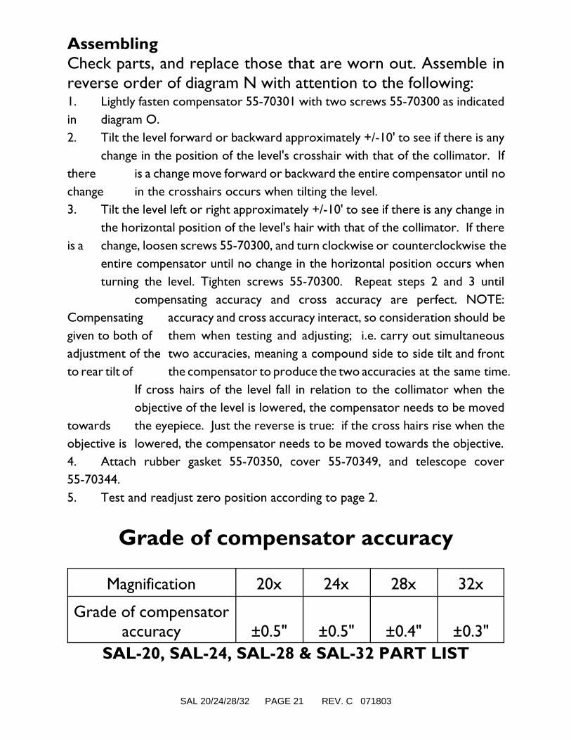
Grade of compensator accuracy
Magnification 20x 24x 28x 32x
Grade of compensatoraccuracy ±0.5" ±0.5" ±0.4" ±0.3"
SAL-20, SAL-24, SAL-28 & SAL-32 PART LIST

SAL 20/24/28/32 PAGE 22 REV. C 071803
PART NUMBER DESCRIPTION SHOWN IN DIAGRAM
55-70300 M3 X 7 COMPENSATOR MOUNTING SCREW N
55-70393 COMPENSATOR- SAL20 N
55-70301 COMPENSATOR- SAL-24 N
55-70400 COMPENSATOR- SAL-28 N
55-70450 COMPENSATOR- SAL32 N
55-70302 RETICLE MOUNT M
55-70303 RETICLE ADJUSTING SCREW M
55-70304 M2 X 6 EYEPIECE CAP SET SCREW M
55-70305 EYEPIECE CAP M
55-70306 RETICLE COVER M
55-70307 M2.5 X 8 EYEPIECE MOUNTING SCREW M
55-70308 EYEPIECE COMPLETE M
55-70309 EYEPIECE GASKET M
55-70310 RETICLE ASSEMBLY- FOR 20, 24, 28 M
55-70401 RETICLE ASSEMBLY- FOR SAL-32 M
55-70311 RETICLE PISTON M
55-70312 "E" CLIP I
55-70313 THREAD TENSIONING RING I
55-70314 REGULATING NUT I
55-70315 LEVEL SCREW SPRING I
55-70316 LEVEL SCREW SLEEVE I
55-70317 LEVEL SCREW I
55-70318 TENSION RING I
55-70319 TEFLON WASHER I
55-70320 SPANNER NUT I
55-70321 LEVEL SCREW & BUSHING ASSEMBLY I
55-70322 FOCUS KNOB COVER L
55-70323 FOCUS KNOB WASHER L

SAL 20/24/28/32 PAGE 23 REV. C 071803
55-70324 M2 X 3 FOCUS KNOB SCREW L
SAL-20, SAL-24, SAL-28 & SAL-32 PART LIST
PART NUMBER DESCRIPTION SHOWN IN DIAGRAM
55-70325 FOCUS KNOB L
55-70326 M2 X 3 FOCUS KNOB SET SCREW L
55-70327 TEFLON WASHER L
55-70328 STOP RING L
55-70329 FOCUS HOUSING L
55-70330 FOCUS GASKET L
55-70331 TEFLON WASHER L
55-70332 WASHER L
55-70333 PINION SHAFT L
55-70335 PINION GUIDE L
55-70336 M2.5 X 10 COVER MOUNTING SCREW H
55-70395 OBJECTIVE CELL ASSEMBLY- SAL-20 K
55-70337 OBJECTIVE CELL ASSEMBLY- SAL-24 K
55-70402 OBJECTIVE CELL ASSEMBLY-SAL-28 K
55-70451 OBJECTIVE CELL ASSEMBLY- SAL-32 K
55-70338 OBJECTIVE GASKET K
55-70339 FOCUS SLIDE SPRING K
55-70340 M2 X 3 MOUNTING SCREW K
55-70396 FOCUS SLIDE- FOR SAL-20 K
55-70341 FOCUS SLIDE- FOR SAL-24 K
55-70452 FOCUS SLIDE- FOR SAL-28 K
55-70403 FOCUS SLIDE- FOR SAL-32 K
55-70342 FOCUSING RACK K
55-70397 FIXED FOCUSING LENS- FOR SAL-20 N
55-70343 FIXED FOCUSING LENS- FOR SAL-24 N

SAL 20/24/28/32 PAGE 24 REV. C 071803
55-70404 FIXED FOCUSING LENS- FOR SAL-28 N
55-70452 FIXED FOCUSING LENS- FOR SAL-32 N
55-70344 TELESCOPE COVER H
55-70345 PEEPSIGHT H
SAL-20, SAL-24, SAL-28 & SAL-32 PART LIST
PART NUMBER DESCRIPTION SHOWN IN DIAGRAM
55-70346 M2.5 X 5 BUBBLE READER MOUNTING SCREW H
55-70347 BUBBLE READER ASSEMBLY H
55-70348M2 X 11 COMPENSATOR COVER MOUNTING
SCREWN
55-70349 COMPENSATOR COVER N
55-70350 COMPENSATOR COVER GASKET N
55-70351 RETICLE HOUSING GASKET M
55-70352 RETICLE ADJUSTING SPRING M
55-70353 TELESCOPE HOUSING H
55-70354 M3 X 5 SPINDLE MOUNTING SCREW H
55-70355 INNER & OUTER CENTER SPINDLE SET H
55-70356 TEFLON WASHER H
55-70357 CIRCLE RETAINER CLIP I
55-70358 HORIZONTAL TANGENT GEAR I
55-70359 M2.5 X 6 TANGENT GEAR SET SCREW I
55-70360 SPRING I
55-70361 M2 X 3 CIRCLE MOUNTING SCREW I
55-70362 LEVEL HEAD RETAINING CLIP H
55-70363 HORIZONTAL CIRCLE RETAINING RING I
55-70364-D HORIZONTAL CIRCLE- DEGREES I
55-70364-G HORIZONTAL CIRCLE- GONS I
55-70365 CIRCLE FRICTION WASHER I
55-70366 LEVEL BASE I
55-70367 RUBBER TANGENT KNOB COVER J

SAL 20/24/28/32 PAGE 25 REV. C 071803
55-70368 M3 X 5 TANGENT KNOB SET SCREW J
55-70369 LEFT TANGENT KNOB J
55-70370 TANGENT SPRING J
55-70371 OUTER SPACER J
55-70372 FRICTION WASHER J
SAL-20, SAL-24, SAL-28 & SAL-32 PART LIST
PART NUMBER DESCRIPTION SHOWN IN DIAGRAM
55-70373 TANGENT SCREW RETAINER J
55-70374 INNER SPACER J
55-70375 DRIVE BUSHING J
55-70376 TANGENT SCREW J
55-70377 M2 X 3 TANGENT LEAF SPRING SCREW J
55-70378 TANGENT LEAF SPRING J
55-70379 RIGHT TANGENT KNOB J
55-70380 BASE COVER I
55-70381 FOOTPLATE I
55-70382 LEVEL SCREW BALL BEARING I
55-70383 BALL BEARING SEAT I
55-70384 M4 X 10 BASE COVER RETAINING SCREW I
55-70385 M3 X 4 OBJECTIVE LOCKING SET SCREW K
55-70386 M2.5 X 6 PEEPSIGHT MOUNTING SCREW H
55-70387 CIRCULAR VIAL SPRING H
55-70388 M2.5 X 6 CIRCULAR VIAL MOUNTING SCREW H
55-70389 CIRCULAR VIAL ASSEMBLY H
55-70390 CARRYING CASE ----
55-70410 LEVEL SCREW BUSHING ASSEMBLY I
55-70411 TANGENT SET SCREW J
55-70412 FOCUSING SET SCREW K
SAL 20/24/28/32 PAGE 26 REV. C 071803
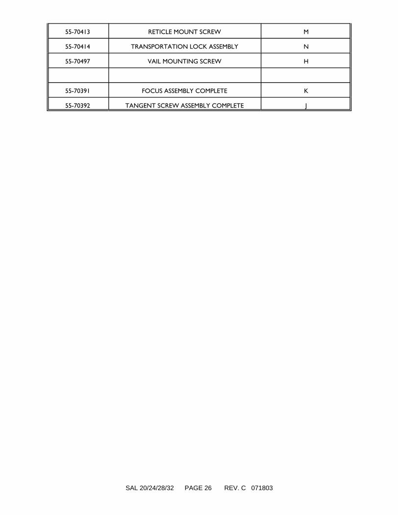
55-70413 RETICLE MOUNT SCREW M
55-70414 TRANSPORTATION LOCK ASSEMBLY N
55-70497 VAIL MOUNTING SCREW H
55-70391 FOCUS ASSEMBLY COMPLETE K
55-70392 TANGENT SCREW ASSEMBLY COMPLETE J