Automatic Fan Regulator
23
Problem Identification Despite the growing popularity of the usage of air conditioners, electric ceiling fans are still widely in use all over country. Air conditioners, though providing users with the option of precision temperature regulation along with several other features, remain largely unaffordable to the majority of consumers. Ceiling fans, on the other hand, with their relatively lower price ranges, easy installation ability and simple control mechanism still remain the most popular domestic cooling appliances for user thermal comfort in tropical countries like Sri Lanka. Presently, conventional choke-styled fan regulators as well as the more expensive smooth dial regulators are available in the market. These give the user the option of setting fan speed as desired depending on ambient environmental status (temperature, humidity etc.) with the latter product affording greater speed variation as opposed to its’ counterpart. Perhaps the major problem with fan regulators currently in the Sri Lankan market is their inability to automatically regulate fan speed corresponding to changes in the external environment. This proves to be somewhat of an inconvenience to the user. One might often set the dial of the regulator to its’ maximum speed prior to going to bed with the room being warm and humid, and yet awake feeling too cold in the morning due to a significant drop in temperature. The opposite too, that of temperature rising at night, although not frequent, is a possibility. Furthermore, existing regulators have the additional disadvantage of not being energy efficient as they even continue to draw the same amount of power when the fan is operating at a slower speed. Preliminary survey for existing products indicated that similar products exist in foreign market for considerable higher prices while such products have not been introduced to Sri Lanka consumer market so far. To address the issues identified, we decided to int roduce a new design with automatic speed regulation in accordance with ambient temperature and low power consumption for an affordable price. Before moving on, we conducted a user survey to get confirmed whether there really is such a necessity for automatic temperature regulation for long and whether for new product has its marketability.
-
Upload
anuruddha-hettiarachchi -
Category
Documents
-
view
230 -
download
0
Transcript of Automatic Fan Regulator

8/3/2019 Automatic Fan Regulator
http://slidepdf.com/reader/full/automatic-fan-regulator 1/23
Problem Identification
Despite the growing popularity of the usage of air conditioners, electric ceiling fans
are still widely in use all over country. Air conditioners, though providing users with the
option of precision temperature regulation along with several other features, remain largely
unaffordable to the majority of consumers. Ceiling fans, on the other hand, with their
relatively lower price ranges, easy installation ability and simple control mechanism still
remain the most popular domestic cooling appliances for user thermal comfort in tropical
countries like Sri Lanka. Presently, conventional choke-styled fan regulators as well as the
more expensive smooth dial regulators are available in the market. These give the user the
option of setting fan speed as desired depending on ambient environmental status
(temperature, humidity etc.) with the latter product affording greater speed variation as
opposed to its’ counterpart.
Perhaps the major problem with fan regulators currently in the Sri Lankan market is
their inability to automatically regulate fan speed corresponding to changes in the external
environment. This proves to be somewhat of an inconvenience to the user. One might often
set the dial of the regulator to its’ maximum speed prior to going to bed with the room being
warm and humid, and yet awake feeling too cold in the morning due to a significant drop in
temperature. The opposite too, that of temperature rising at night, although not frequent, is a
possibility. Furthermore, existing regulators have the additional disadvantage of not being
energy efficient as they even continue to draw the same amount of power when the fan is
operating at a slower speed. Preliminary survey for existing products indicated that similar
products exist in foreign market for considerable higher prices while such products have not
been introduced to Sri Lanka consumer market so far.
To address the issues identified, we decided to introduce a new design with automatic
speed regulation in accordance with ambient temperature and low power consumption for an
affordable price.
Before moving on, we conducted a user survey to get confirmed whether there really
is such a necessity for automatic temperature regulation for long and whether for new product
has its marketability.

8/3/2019 Automatic Fan Regulator
http://slidepdf.com/reader/full/automatic-fan-regulator 2/23
User Survey
Group members interviewed 50 people from various parts of the country spanning
across various socio-economic divisions in order to accurately assess what an average Sri
Lankan consumer would require as improvements to existing fans/fan regulators available in
the market.
Each interviewee too was asked to fill in a form detailing the various pieces of
information required. The divisions were as follows:
Age division (young/old)
Income status division (affluent/low income generating)
Geographic locality (urban/rural)
Educational Status (educated/uneducated)
According to gender (male/female)
Results (Summarized) * † * Appendix A for details † Appendix B for Survey form

8/3/2019 Automatic Fan Regulator
http://slidepdf.com/reader/full/automatic-fan-regulator 3/23

8/3/2019 Automatic Fan Regulator
http://slidepdf.com/reader/full/automatic-fan-regulator 4/23
Based on the data collected above, predominant needs appearing multiple times
across all listed categories were identified.
Out of major needs identified above, two significant needs have been accounting for
more than 50% of all needs. Those are,
Facility of remote control.
Automatic Remote Speed Control in according with ambient temperature.
Although Automatic speed control would satisfy the necessity of having remote
control and adding remote control increases the total cost, we decided to consider the facility
of remote control in conceptual design while having a thought of dropping that feature if itadds unnecessary complexity to the design. Then we developed the following design
specifications taking above mentioned user needs and technical issues in to consideration.
5%
23%
31%4%
3%
3%
3%
3%
25%
Major Needs Identified
Power Saving Mechanism
Automatic Control depending onRoom being too Warm/Cold
Remote Control
Display Options
Operation during Power Failure
Dust Removal Mechanism
Automatic On/Off Switching
Uniform/Directed Blowing

8/3/2019 Automatic Fan Regulator
http://slidepdf.com/reader/full/automatic-fan-regulator 5/23
Design Specifications
Interface to switch the fan on and off.
Interface to switch between auto and manual mode.*
Interface to set reference temperature (In auto mode) Interface to set fan speed (In manual mode)*
Continues variation of speed in accord ance with ambient temperature. †
* Even though the user survey doesn’t indicate any necessary for both auto and manual modes together there isan issue arises when manual control is necessary for some special cases. So we decided to add both auto andmanual mode to work in harmony.
† Even though user need survey does not indicate continues variation of speed in accordance with temperature,we added it as a hidden need as it makes consumer more comfortable and does not require extra cost.
To fulfil the above we came up with 2 different conceptual designs.
Conceptual Designs
Design 1
In auto mode of operation, the reference temperature value set by the user and
ambient temperature value read through the temperature sensor are fed into control unit. The
control unit calculates the error between two values and generates a signal accordingly and
passes it to voltage regulator. Voltage regulator regulates the power input to the fan in
accordance with the signal received from control unit.
In manual mode of operation, only the speed value set by the user is fed into control
unit and then the control unit generates a signal with respect to the error value between
received value and pre-defined reference value. This calculated value is fed into the voltage
regulator which regulates the power input to the fan in accordance with received signal.
Design 2
Temperature sensor and the user interface are located in a remote control. It sends the
values read through sensor and user interface to a receiver which is placed inside a gadget
which is attached to fan itself. All other functions are similar to the conceptual design 1
except the facility of remote control.
8/3/2019 Automatic Fan Regulator
http://slidepdf.com/reader/full/automatic-fan-regulator 6/23
Design 1- Block Diagram

8/3/2019 Automatic Fan Regulator
http://slidepdf.com/reader/full/automatic-fan-regulator 7/23
Design 2- Block Diagram

8/3/2019 Automatic Fan Regulator
http://slidepdf.com/reader/full/automatic-fan-regulator 8/23
User Input
Variable Resistor
Power Circuit
Rectif y_and_Regulate_Voltage
VDD_12V
GND
VDD_5V
AC_In1AC_In2
AC_Power
230V50Hz
T1
TRANSFORMER
1 5
4 8
Temperature Sensor LM351
2
3VI
GND VO
Zero Crossing Detector
Zero_Crossing_Detection
VDD_12V
AC_In2
GND
AC_In1Output to thePIC
01
Intelligent Fan Regulator
A
1 7Thursday, September 22, 2011
Title
Size Document Number Rev
Date: Sheet of
Control Unit
PIC
Temperature Sensor INPUT
Variable Resistor IN PUT
Power
Zero Crossing INPUT
OUTPUT to TRIAC Circuit
FAN
2
1
TRIAC Circuit
TRIAC_CIRCUIT
INPUT1
INPUT2
OUTPUT1OUTPUT2
Even though the 2 nd conceptual design provides the consumer with more comfort and
ease of use, its higher cost draws back the demand for it. So we decided to start with the 1 st
conceptual design as it is more economical and fulfills the user needs to a satisfactory level.
Preliminary design
As we chose 1 st conceptual design to work on, we come up with a preliminary design
which describes the implementation process of 1 st conceptual design. We employed top down
hierarchical design technique as we are novel to the subject and also the design is a new one.
Top most level of the design
Take the user input from variable resister and varies the fan speed in accordance with
ambient temperature sensed from the temperature sensor (LM35).

8/3/2019 Automatic Fan Regulator
http://slidepdf.com/reader/full/automatic-fan-regulator 9/23
VDD_5V
Voltage_Regulator_Circuit
Regulate_Voltages
DC_12V
GND
VDD_12V
VDD_5V
GND
Rectri
Rectify
AC_In1 DC_12V
AC_In2 GND
AC_In2 GND
VDD_12VAC_In1
Control Unit
PIC
Temperature Sensor INPUT
Variable Resistor I NPUT
PowerZero Crossing INPUT
OUTPUT to TRIAC Circuit
PIC 16F877A
PIC16F877A
20
32
19
27
2625
1
24232221
1112131415161718
23456789
4039383736353433
302928
OSC2/CLKOUT
MCLR/VPP
OSC1/CLK
TEST
RA0/INTRA1/T0CLK
VDD
RA2RA3
RA4/RX/DTRA5/TX/CK
RB0/CAP1RB1/CAP2
RB2/PWM1RB3/PWM2
RB4/TCLK12RB5/TCLK3
RB6RB7
RC0/AD0RC1/AD1RC2/AD2RC3/AD3RC4/AD4RC5/AD5RC6/AD6RC7/AD7
RD0/AD8RD1/AD9RD2/AD10RD3/AD11RD4/AD12RD5/AD13RD6/AD14RD7/AD15
RE0/ALERE1/OERE2/WR
Temperature Sensor INPUT
Variable Resistor INPUT
Zero Crossing INPUT
Power
OUTPUT to TRIAC Circuit
Major blocks used for top level
Power Circuit
Control Unit
Zero Crossing Detector
TRIAC Circuit
Second Level of the Design
Power circuit
Employs a rectifier circuit and a voltage regulator circuit to convert normal AC to12V and 5V DC to feed control circuit and other peripheral circuits with.
Control Circuit
Employs a PIC16F877A microcontroller to calculate error between user input and
temperature sensor input and to generate a pulse accordingly.

8/3/2019 Automatic Fan Regulator
http://slidepdf.com/reader/full/automatic-fan-regulator 10/23
Zero Crossing Detector
Zero_Crossing_Detection
VDD_12V
AC_In2
GND
AC_In1Output to the PIC
AC_In1
C1
1n
R2 1
VDD_12V
R
2
1
AC_In2
Output to the PIC
R2 1
U1A
LM6152BCN
2
3
4
1
8
-
+ V -
OUT
V +
GND
TRIAC Circuit
TRIAC_CIRCUIT
INPUT1
INPUT2
OUTPUT1OUTPUT2 R1
1k
U1MOC3011
1
2
6
4
R3
1k
U2BT136
1
2
3VI
G N D
VO
INPUT1
OUTPUT1
INPUT2
R2
1k
OUTPUT2
Zero Crossing Detector
Employs a LM 339 zero crossing detector to detect zero crossing of AC and to informmicrocontroller through an interrupt.
TRIAC and Octocoupler Circuit
Employs an octocoupler (µOC 3011) to isolate AC and DC circuit portions and
TRIAC (BT 136) to regulate the fan speed by controlling power supplied to fan.

8/3/2019 Automatic Fan Regulator
http://slidepdf.com/reader/full/automatic-fan-regulator 11/23
Rectri
Rectify
AC_In1 DC_12V
AC_In2GND
AC_In2
0
GND
D4
D1N4007
D2
D1N4007
C1
500u
D3
D1N4007
DC_12V
D1
D1N4007
AC_In1
D5
D1N4494
Voltage_Regulator_Circuit
Regulate_Voltages
DC_12V
GND
VDD_12V
VDD_5V
GND
GND
VDD_5VC3
0.33u
U1MC7805C
1 2
3
IN OUT G N D
VDD_12V
GND
U2MC7812C
1 2
3
IN OUT G N D
C2
0.1u
0
C4
0.1u
C1
0.33u
DC_12V
Third level of design (for power circuit)
Rectifier Circuit
Employs IN40075 in a full wave rectifier bridge.
Voltage Regulator Circuit
Employs 7812 and 7805 voltage regulators to regulate DC at 12V and 5V respective.
Enclosure Design
After obtaining an accurate preliminary design, we next moved on to designing of
proper enclosure for our product. We were able to come up with a suitable enclosure which
suits the design as follows.

8/3/2019 Automatic Fan Regulator
http://slidepdf.com/reader/full/automatic-fan-regulator 12/23

8/3/2019 Automatic Fan Regulator
http://slidepdf.com/reader/full/automatic-fan-regulator 13/23

8/3/2019 Automatic Fan Regulator
http://slidepdf.com/reader/full/automatic-fan-regulator 14/23

8/3/2019 Automatic Fan Regulator
http://slidepdf.com/reader/full/automatic-fan-regulator 15/23

8/3/2019 Automatic Fan Regulator
http://slidepdf.com/reader/full/automatic-fan-regulator 16/23
PCB Design
PCB design which suits to the enclosure.

8/3/2019 Automatic Fan Regulator
http://slidepdf.com/reader/full/automatic-fan-regulator 17/23
Part List
Part Reference
0.33u C10.1u C20.33u C30.1u C4500u C101n C12D1N4007 D1D1N4007 D2D1N4007 D3D1N4007 D4D1N4494 D5Ceiling FANCON4 J1PIC_16F877A PIC_16F877A1k R11k R21k R3Ceiling R50Ceiling R51Ceiling R52
TRANSFORMER T1MOC3011 U1MC7812C U2LM6152BCN U4MC7805C U10BT136 U11

8/3/2019 Automatic Fan Regulator
http://slidepdf.com/reader/full/automatic-fan-regulator 18/23
00.5
11.5
22.5
33.5
4
4.5
PS TS AC HS B MR RPM PL SD RC
F r e q u e n c y
Need (Key)
Agewise Need Distribution
Below 30
Above 30
Appendix A
Data has been presented according to the five divisions mentioned above along with
suitable histograms to enhanced clarity of the information.
Age Division
Table 1: Problems and Needs Identified by Users According to Age Category
Problems IdentifiedAge Category
Needs IdentifiedAge Category
< 30 > 30 < 30 > 30
High electricitybill/consumption 2 2 Power saving mechanism (PS) 1 1
Problem of having to go to the
regulator in order to vary speed3 Temperature sensitivity (TS) 3
Noisy operation 1 Automated control (AC) 1
Absence of mosquitoerepellent 1 Humidity sensitivity (HS) 1
Absence of automatic ambienttemperature sensitivity 1 Bulb fixed to ceiling fan (B) 1
Malfunctioning timers 1 Mosquitoe repellent (chemicalagent) (MR) 1
Dryness of skin 1 Display RPM (RPM) 1
Dust accumulation anddifficulty involved in cleaning 4 Fan to work even during power
failure (PF) 1
Breathing difficulties due tohigh speeds 1
Mechanism to prevent drynessof skin during operation (SD) 1
Remote control capability(RC) 4
Figure 1: Histogram of Needs Identified by Users According to Age Category

8/3/2019 Automatic Fan Regulator
http://slidepdf.com/reader/full/automatic-fan-regulator 19/23
Income Status
Table 2: Problems and Needs Identified by Users According to Income Status Category
Problems IdentifiedMonthlyIncome
Needs Identified
MonthlyIncome
< 15,000LKR
> 15,000LKR
< 15,000LKR
> 15,000LKR
Noisy operation 1 1 Continuous speed regulation(CS) 1
Requirement for frequentrepairing 1 Remote Control (RC) 1 1
High electricity consumption 1 1 Embedded devices instead of mechanical control (ED)
1
Dust accumulation 2Flexibility with alternativepower sources (FAP) 1Ability to orient direction of blowing (OD) 1
Timer option (TO) 1
Automatic speed control (AC) 1
Figure 2: Histogram of Needs Identified by Users According to Income Status Category
00.5
11.5
22.5
33.5
44.5
CS RC ED FAP OD TO AC
F r e q u e n c y
Need (Key)
Income Generation Status Based Need Distribution
Low Income
Affluent

8/3/2019 Automatic Fan Regulator
http://slidepdf.com/reader/full/automatic-fan-regulator 20/23
Geographic Locality
Table 3: Problems and Needs Identified by Users According to Geographic Locality
Problems IdentifiedLocality
Needs IdentifiedLocality
Urban Rural Urban Rural
Noisy operation 1 2 Automatic fan speed controlaccording to room temperature 3 2
Drop of temperature during thenight (getting too cold) 1 2 Remote control (RC) 1
High electricity consumption 1 Power saving mechanism (PS) 1
Dust accumulation 1
Figure 3: Histogram of Needs Identified by Users According to Geographic Locality
00.5
11.5
22.5
33.5
44.5
AC RC PS
F r e q u e n c y
Need (Key)
Geogrophical Location Base Need Identification
Urban
Rural

8/3/2019 Automatic Fan Regulator
http://slidepdf.com/reader/full/automatic-fan-regulator 21/23
Educational Status
Table 4: Problems and Needs Identified by Users According to Educational Status Category
Problems IdentifiedStatus
Needs IdentifiedStatus
UptoO/L
AboveO/L
UptoO/L
AboveO/L
Health issues 2 1Automatic switching on/off depending on human presence(AS)
2
Dryness of skin 1 Remote Control (RC) 3 1
Non-uniform blowing 1 Display Options (DO) 1
Dust accumulation 2 Dust removal mechanism (DR) 2
Motor getting weak 1 Automatic speed control (AC) 2
Absence of timer features 1
Figure 4: Histogram of Needs Identified by Users According to Educational Status Category
00.5
11.5
22.5
33.5
44.5
RC ASO DO DR AC
F r e q u e n c y
Need (Key)
Educational Status Based Need Distribution
Upto GCE O/L
Above GCE O/L
8/3/2019 Automatic Fan Regulator
http://slidepdf.com/reader/full/automatic-fan-regulator 22/23
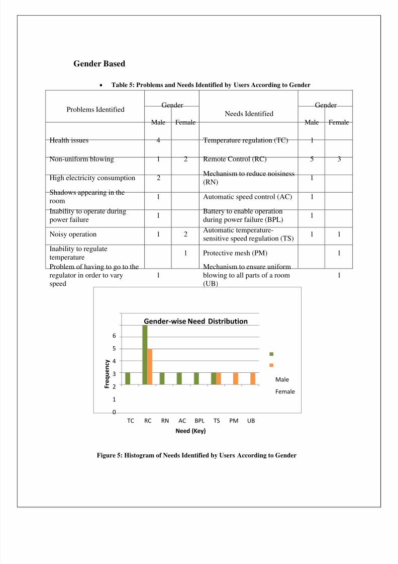
Gender Based
Table 5: Problems and Needs Identified by Users According to Gender
Problems IdentifiedGender
Needs IdentifiedGender
Male Female Male Female
Health issues 4 Temperature regulation (TC) 1
Non-uniform blowing 1 2 Remote Control (RC) 5 3
High electricity consumption 2 Mechanism to reduce noisiness(RN) 1
Shadows appearing in theroom 1 Automatic speed control (AC) 1
Inability to operate duringpower failure 1 Battery to enable operation
during power failure (BPL) 1
Noisy operation 1 2 Automatic temperature-sensitive speed regulation (TS) 1 1
Inability to regulatetemperature
1 Protective mesh (PM) 1
Problem of having to go to theregulator in order to varyspeed
1Mechanism to ensure uniformblowing to all parts of a room(UB)
1
Figure 5: Histogram of Needs Identified by Users According to Gender
0
1
2
3
4
5
6
TC RC RN AC BPL TS PM UB
F r e q u e n c y
Need (Key)
Gender-wise Need Distribution
Male
Female

8/3/2019 Automatic Fan Regulator
http://slidepdf.com/reader/full/automatic-fan-regulator 23/23
Appendix B
User Survey Form
Age : .....................................Residence (urban/rural) : ........................................District : .....................................Profession : .....................................Gender : .....................................
1. Do you have an air conditioner at home (yes/no)?
2. Do you have a fan at home? (yes/no) if yesCeiling fan : .........................Table fan : .........................
3. At what time of the day do you mostly use your air conditioner/fan? (Morning / Afternoon / At Night)
4. What are the problems you face when using your fan?..............................................................................................................................................................................................................................................................................................................................................................................................................................
5. What improvement would you like to have included in your fan?..............................................................................................................................................................................................................................................................................................................................................................................................................................
6. If you had an air conditioner instead of a fan, you would (like it / would not like it / makeno difference)Reason : ..................................................................................................................................
7. How many units of electricity do you consume per montha. Less than 60b. Between 60 and 90c. Between 90 and 150d. Between 150 and 300e. Do not know
8. Are you concerned about the power consumption of the electric goods you purchase?
..........................................................................................................................................