Automatic Control Systems -Lecture Note 14-
36
1/36 Automatic Control Systems Modeling of Physical Systems 4 Automatic Control Systems -Lecture Note 14-
Transcript of Automatic Control Systems -Lecture Note 14-

1/36
Automatic Control Systems
Modeling of Physical Systems 4
Automatic Control Systems -Lecture Note 14-

2/36
Automatic Control Systems
Introduction
Modeling : mathematical description of physical system based
on corresponding physical laws
Model : differential equation, state equation, or transfer function
used in simulation, analysis, and control design
i) LTI system
ii) LTV system
iii) Nonlinear LTI system
iv) Nonlinear LTV system
Real Physical System Mathematical Model Modeling

3/36
Automatic Control Systems
Modeling of Electrical Networks
【Example1】
Network Equation
Loop Method
Node Method
State-Variable Method
(used in modern control design)
□ Modeling of Electrical Networks

4/36
Automatic Control Systems
Modeling of Electrical Networks
Voltage in L :
Current in C :
i) State-space representation
State : , Output : ,
Input :
(1) tetetRi
dt
tdiL c
(2) ti
dt
tdeC c
teti c , tytec
ti
tety
tu
Lti
te
L
R
L
C
dt
tdidt
tde
tute
c
c
c
01
10
1
10

5/36
Automatic Control Systems
Modeling of Electrical Networks
State-Diagram
Another state-space representation
State : , Output : ,
Input :
“optional”
1 2 , c ce t x t e t x t
tytec
tute

6/36
Automatic Control Systems
Modeling of Electrical Networks
(2) → (1) :
1 1
22
1
2
0 1 0
1 1
1 0
c c cLC e t RC e t e t e t
x t x tu tR
x tx t LC L LC
x ty t
x t

7/36
Automatic Control Systems
Modeling of Electrical Networks
ii) Transfer function representation
if is output
1
1
1111
11
2
2
2
RCsLCs
sLCsL
RsLC
sE
sEc
1111
1
11
2
2
RCsLCs
Cs
sLCsL
RsL
sE
sI
ti

8/36
Automatic Control Systems
DC Motors
Servo Motors (accurate motors for control purpose)
i) AC Motors : cheap, robust, hard to control (due to
nonlinearity)
ii) DC Motors : expensive, easy to control
□ DC Motors

9/36
Automatic Control Systems
DC Motors
Basic Operation Principle
electro-magnetic force

10/36
Automatic Control Systems
DC Motors
If the conductor is free to move, then it generates
back electromotive force (back e.m.f.)
will be opposing the magnetic flux (by Lenz's law)
conductor) oflength : (motor of principle ; lliBf
vlBeb
be

11/36
Automatic Control Systems
DC Motors
In addition, Faraday's law says
or
DC motor
flux coupling :
dt
deb
generator of principle vlBeb
generation voltageemf
generation torque
vlBe
liBf
b

12/36
Automatic Control Systems
DC Motors

13/36
Automatic Control Systems
DC Motors
Actual DC Motor
Schematic diagram of a DC motor

14/36
Automatic Control Systems
DC Motors
Commutator wiring

15/36
Automatic Control Systems
DC Motors
Physical configuration of the rotor of DC motor

16/36
Automatic Control Systems
DC Motors
Classification of PM DC Motors
Iron-Core PM DC Motor
17/36
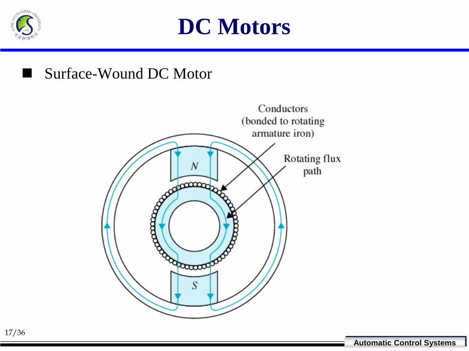
Automatic Control Systems
DC Motors
Surface-Wound DC Motor

18/36
Automatic Control Systems
DC Motors
Moving-Coil DC Motor

19/36
Automatic Control Systems
DC Motors
Brushless DC Motor

20/36
Automatic Control Systems
DC Motors
Brushless DC Motor (BLDC Motor) System
PM (Permanent Magnet) rotor DC motor
Use electronic switching of current in the stator winding
segments to accomplish commutation

21/36
Automatic Control Systems
DC Motors
DC Motor Equations

22/36
Automatic Control Systems
DC Motors

23/36
Automatic Control Systems
DC Motors
Basic Equations
i) magnetic torque :
ii) back e.m.f. :
iii) field circuit :
or (1)
( : , t : )
m f a m m a i a
a
T t ki t i t T t k t i t K i t
maganetic flux i armature current
(2)
( : )
m
b b b m
m
d te t K K t
dt
angular velocity
dt
tdiLtiRte
f
ffff

24/36
Automatic Control Systems
DC Motors
iv) armature circuit :
v) mechanical eq. of motor :
where : moment of inertia, : load torque,
: equivalent damping constant
(4)
2
2
tTtTtBdt
tdJ mLmm
mm
te
Lti
L
Rte
Ldt
tdi
tedt
tdiLtiRte
b
a
a
a
aa
a
a
ba
aaaa
11
(3)
mJLT
mB

25/36
Automatic Control Systems
DC Motors
State space model
• • •
•
•
•
, ,
, ,
0 1
10 0
00 1 0 0
0 0 1
a m m
a m m m
a b
a aaaa
i mm m a L
m m m
mm
m
state variable i t t t
i
R K
L L oiLi
K Re t T t
J J J
로 정리
a
m
m
i

26/36
Automatic Control Systems
DC Motors
Transfer function from to tea m t
2
(1)
(2)
(3)
1
(4)
1
m i a
b b m
a a a a b
a a b
a a
m m m L m m
m m m L m m
m m L
m m
T s K I s
E s K Ω s
E s L s R I s E s
I s E s E sL s R
T s B Ω s T s J s Θ s
T s B Ω s T s J sΩ s
Ω s T s T sJ s B
and
1
m mΘ s Ω ss

27/36
Automatic Control Systems
DC Motors
0
3 2
1
1
11
L
i
m a a m m
ia T b
a a m m
i
a m a m m a b i a m
K
Θ s L s R J s B
KE s sK
L s R J s B
K
L J s R J B L s K K R B s
28/36
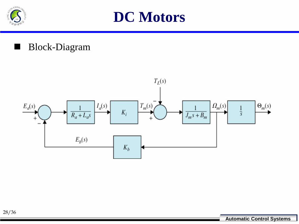
Automatic Control Systems
DC Motors
Block-Diagram

29/36
Automatic Control Systems
DC Motors
Steady State Torque-Speed Curves of DC Motor
In the steady state, are constants.
From (3), (∵ steady-state),
where : No-load speed,
bb
aa
mm
m
aa
Ete
Ete
TtT
tw
Iti
m
0
dt
tdia
1 1 0
s
mmm
a
bm
ai
a
mb
i
mabaaa
T
T
E
KT
EK
R
KK
TREIRE
b
a
K
E0

30/36
Automatic Control Systems
DC Motors
: Stalling torque of motor
a
ais
R
EKT

31/36
Automatic Control Systems
DC Motors
The shape of the steady state speed-torque curve will be
modified if a common voltage supply is used to excite both the
field winding and the armature winding.
There are three arrangements
i) Shunt-wound motor
ii) Series-wound motor
iii) Compound-wound motor

32/36
Automatic Control Systems
DC Motors

33/36
Automatic Control Systems
DC Motors
DC Servomotors

34/36
Automatic Control Systems
DC Motors
Control of DC Motors
Two methods of control
i) Armature Control
- voltage to the rotor circuit is varied.
- suitable for speed control
ii) Field Control
- voltage to the field circuit is varied
- suitable for constant power drives
iii) phase-locked control, thyristor control, and others
ae
, mbbab Keee
fe
, where is constant m f a aT ki i i

35/36
Automatic Control Systems
DC Motors
Torque Motors
High torque DC motors with PM stators
suitable for
i) direct-drive application (ex, robot arm)
ii) high-precision application
iii) valve actuators in hydraulic servovalves
more expensive

36/36
Automatic Control Systems
DC Motors
Harmonic Drives
To increase the output torque (gear system)