Automated Test for NASA CFS · Automated Test for NASA CFS David C. McComas 1, Susanne L. Strege 1,...
13
Automated Test for NASA CFS David C. McComas 1 , Susanne L. Strege 1 , Paul B. Carpenter 2 , Randy Hartman 2 1 NASA Goddard Space Flight Center 2 EXB Solutions, Inc. (EXB) Abstract The core Flight System (cFS) is a flight software (FSW) product line developed by the Flight Software Systems Branch (FSSB) at NASA’s Goddard Space Flight Center (GSFC). The cFS uses compile-time configuration parameters to implement variable requirements to enable portability across embedded computing platforms and to implement different end-user functional needs. The verification and validation of these requirements is proving to be a significant challenge. This paper describes the challenges facing the cFS and the results of a pilot effort to apply EXB Solution’s testing approach to the cFS applications. KEYWORDS - Core Flight Software, Software Reuse, Test Automation, API, FSW core Flight System (cFS) Overview The core Flight System (cFS) is a flight software (FSW) product line developed by the Flight Software Systems Branch (FSSB) over the past 10 years. The cFS uses a layered architecture with four distinct layers as shown in Figure 1 cFS Architecture Layers. Layer 1 contains the Operating System (OS) and Board Support Package (BSP) and access to the functionality in these components is controlled through two Application Programmer’s Interfaces (APIs): the Operating System Abstraction Layer (OSAL) and the Platform Support Package (PSP). The OSAL and PSP APIs provide a platform independent (OS and hardware) interface that provides common OS and BSP services. Layer 2 contains the core Flight Executive (cFE) that provides services, which has proven to be common across most FSW projects. The APIs in Layers 1 and 2 have been instrumental in the cFS’ success across multiple platforms and these APIs have remained stable for the past few years. Together they define an application runtime environment and have enabled a community of cFS users to create an “App Store.” Applications reside in Layer 4 and Application Libraries (e.g. linear algebra math library), which can be shared among multiple applications, reside in Layer 3. Previous FSW reuse efforts have not attained all of the benefits of reuse because they employed a “clone and own” approach. A new project would copy FSW components from one or more previous missions based on functional requirement similarities. Usually the code would be tweaked and the entire verification and validation effort had to be performed for the new mission. Therefore the cost savings were limited and since FSW components were not configuration managed separately from projects component quality did not necessarily increase because a single lineage for each component was not maintained. https://ntrs.nasa.gov/search.jsp?R=20150020918 2019-02-11T20:05:07+00:00Z
Transcript of Automated Test for NASA CFS · Automated Test for NASA CFS David C. McComas 1, Susanne L. Strege 1,...

Automated Test for NASA CFS
David C. McComas 1, Susanne L. Strege 1, Paul B. Carpenter 2, Randy Hartman 2
1 NASA Goddard Space Flight Center 2 EXB Solutions, Inc. (EXB)
Abstract
The core Flight System (cFS) is a flight software (FSW) product line developed by the Flight Software Systems Branch (FSSB) at NASA’s Goddard Space Flight Center (GSFC). The cFS uses compile-time configuration parameters to implement variable requirements to enable portability across embedded computing platforms and to implement different end-user functional needs. The verification and validation of these requirements is proving to be a significant challenge. This paper describes the challenges facing the cFS and the results of a pilot effort to apply EXB Solution’s testing approach to the cFS applications.
KEYWORDS - Core Flight Software, Software Reuse, Test Automation, API, FSW
core Flight System (cFS) Overview
The core Flight System (cFS) is a flight software (FSW) product line developed by the Flight Software Systems Branch (FSSB) over the past 10 years. The cFS uses a layered architecture with four distinct layers as shown in Figure 1 cFS Architecture Layers. Layer 1 contains the Operating System (OS) and Board Support Package (BSP) and access to the functionality in these components is controlled through two Application Programmer’s Interfaces (APIs):
the Operating System Abstraction Layer (OSAL) and the Platform Support Package (PSP). The OSAL and PSP APIs provide a platform independent (OS and hardware) interface that provides common OS and BSP services. Layer 2 contains the core Flight Executive (cFE) that provides services, which has proven to be common across most FSW projects. The APIs in Layers 1 and 2 have been instrumental in the cFS’ success across multiple platforms and these APIs have remained stable for the past few years. Together they define an application runtime environment and have enabled a community of cFS users to create an “App Store.” Applications reside in Layer 4 and Application Libraries (e.g. linear algebra math library), which can be shared among multiple applications, reside in Layer 3.
Previous FSW reuse efforts have not attained all of the benefits of reuse because they employed a “clone and own” approach. A new project would copy FSW components from one or more previous missions based on functional requirement similarities. Usually the code would be tweaked and the entire verification and validation effort had to be performed for the new mission. Therefore the cost savings were limited and since FSW components were not configuration managed separately from projects component quality did not necessarily increase because a single lineage for each component was not maintained.
https://ntrs.nasa.gov/search.jsp?R=20150020918 2019-02-11T20:05:07+00:00Z

Figure 1 cFS Architecture Layers
cFS Lifecycle Reuse
To improve upon the shortcomings of the “clone and own” approach, the cFS takes the entire FSW lifecycle into account and contains reusable artifacts for each phase as shown in Figure 2, Trace Configuration Parameters. The shaded components are cFS artifacts and the <p> notation indicates a parameterized artifact. The following steps illustrate a typical cFS project deployment:
1. Requirements Management
a. The FSW team receives project requirements. These requirements are traced to existing cFS subsystem requirements. Most if not all of the requirements at this level are implemented by cFS applications so a FSW systems engineer can tailor the cFS to a project by selecting the appropriate cFS applications. These options will
continue to grow as the cFS App Store contains more apps.
b. The detailed FSW requirements are instantiated by selecting specific configuration parameters for parameterized requirements.
2. Code Instantiation
a. The cFS configuration parameters are contained in C header files that are set by the FSW team. These parameters are refined as the development effort matures.
b. Note in Figure 2 that some configuration parameters trace to requirements and some are only contained in the C header files. The header-only parameters are design in nature and do not impact functional requirements. For example default file paths and names are defined as configuration parameters and these do not trace to a functional requirement.
cFE App 1 cFE
App 1 cFE
App 1 cFE
App 1
OS Abstraction API
cFE API
Application Library
Member Application Libraries
cFE Apps
(5)
Application Layer
Application Library Layer
Executive Layer
Platform Abstraction Layer
cFE Core
OS Abstractions (Linux, RTEMS,
VxWorks)
cFE Platform Support Packages
cFE PSP API
Member Apps
Community Controlled Member Controlled Community Archived

Figure 2 Trace of Configuration Parameters
3. Verification and validation
a. Typically a project does not rerun component unit tests. These tests have been designed to test all source lines and to provide reasonable coverage of path coverage. The current unit tests have not been design to adapt to project-specific configuration parameters. In addition requirements are not “checked off” at the unit level.
b. The current cFS artifacts do not include integration tests. Projects must perform this step to verify the cFS properly functions as a system.
c. The cFS build test verify functional requirements and these have been designed to read in the C header files and adapt the test accordingly so the project instantiated functional requirements can be verified. However, the cFS build test execute on the Advanced Spacecraft Integration & System Test (ASIST) ground system so if a project is using a
different ground system then the build test can’t be rerun as delivered.
d. Most GSFC projects perform system level test which are design based on user scenarios rather than from a functional requirements perspective. The cFS artifacts do not cover this level of testing.
The cFS product line approach has proven to be effective for achieving more comprehensive FSW reuse and for reducing cost however there are still challenges in the verification and validation processes. There are a large number of configuration parameters with an extremely large number of parameter setting permutations. cFE version 6.3 contains 139 configuration parameters and the number of configuration parameters per app currently ranges from 8-45. The cFS applications also make use of tables. A table is a collection of data elements that can be loaded during runtime and most tables have default values that must be tuned by a project.
Detailed Requirements
Code Unit (Developer)
Build Test (Tester)
FSW Subsystem Requirements
Integration Test (Developer)
System Test (Tester)
Project Requirements
CFS Repository
<p>
<p> CFS Repository
<p>
<p>
<p>

The configuration parameters and table variables can be thought of as a configuration space. It is cost prohibitive to test the entire configuration space. The unit tests are only run against a single set of C header configuration parameters and tables are populated with whatever values help test code paths. The build tests can adapt to configuration parameter setting but due to cost constraints they have only been run using a single set of configurations.
Projects are faced with the decision whether to rerun the build test using the project’s configuration settings or to accept the risk of not fully testing the functional requirements with the project’s configuration. There are several factors influencing this decision. Is the project using the ASIST ground system that allows them to rerun the cFS build test suite? Does the project have the expertise required to rerun the build test and interpret the results? When will the project’s configuration settings be stable? How much effort has the project put into the integration testing?
There is another more fundamental question that challenges the reuse approach itself. We use or reuse operating systems and they have tunable configurations however we don’t trace them to higher level functional requirements and rerun verification tests (one could argue we should, provided we have adequate budgets). Operating systems implement design requirements that provide the infrastructure for implementing user functional requirements. In this respect the OSAL and PSP are similar to operating systems but as we move up the cFS layers the functionality is traceable to user requirements. Therefore the cFE and cFS application requirements are traced to project requirements and verified within a project’s context and configuration. It is on this premise that the cFS reuse is treated
differently than the use of an operating system.
cFS Community with an ‘App Store’
The cFS continues to gain in popularity among the NASA centers and has made inroads into the commercial sector. Goddard Space Flight Center’s Lunar Reconnaissance Orbiter (LRO) launched in 2009 uses the cFE and the Global Precipitation Measurement (GPM) launched in 2014 and the Magnetospheric Multi-scale Mission Spacecraft (MMS) launched in March 2015 used the complete cFS. The Ames Research Center’s Lunar and Dust Environment Explorer (LADEE) spacecraft launched in 2014 and Johnson Space Center’s Morpheus project tested in 2013 use the complete cFS. The Johns Hopkins University Applied Physics Lab’s Radiation Belt Storm Probe launched in 2012 uses the cFE. In addition to these projects other NASA centers are evaluating the cFS for use in their projects and multiple cFS-based Space Act Agreements are being pursued with commercial enterprises.
As the cFS user base continues to expand efforts are underway to establish a cFS community that would facilitate a cFS app store. There are currently 12 cFS applications and as the community matures this number is expected to increase significantly. Therefore the verification/validation effort will also increase exponentially if we assume a similar number of 8 to 45 configuration parameters per application. In addition each application will continue to be maintained and this maintenance will require regression testing. Therefore a more advanced approach towards testing is needed. ___

NASA/EXB - Joint Project Description
A subset of applications including the Health and Safety (HS) application software requirements were selected to demonstrate the value of EXB’s Software Requirements-Based Testing Methodology and automated testing process. EXB executes a requirements-based test generation process applicable to all levels of test development and execution. The process includes thorough analysis of the software requirements, the use of EXB’s TestCompass® toolset and automation of test case and test procedure development. In the case of the cFS the process facilitated the implementation of auto execution of testing. Finally it supports resource allocation, status, trace, and coverage reports.
Scope of the Pilot Project
NASA Goddard identified two areas of concern to be addressed during the pilot are: cost effective maintenance of requirements-based application tests and 100% testing coverage of the configuration space.
EXB was given the Software Requirements Document for the Health and Safety Application to use as the example for requirements-based testing. EXB used the boundary definitions of the configuration parameters defined in header files as the basis for test case generation.
During a follow-on contract EXB evaluated nine additional applications using the same methodology.
EXB’s Software Requirements-Based Testing Methodology
There is a trade-off in software testing between budget, time and quality. Typically, when quality is paramount, time and budget are increased. The goal of the Methodology is
to improve quality, while using automation to reduce budget and schedule.
Two specific areas of quality improvement emphasized by the EXB Methodology are data boundary testing and logic testing. EXB’s TestCompass software automatically generates test cases for low bound, just above low bound, high bound, and just below high bound; and optionally, just below low bound and just above high bound. These test cases ensure that data bounds are thoroughly tested. TestCompass also generates test cases that ensure Multi-Condition/Decision Coverage (MCDC) of logic statements which is a requirement for safety-critical avionics systems. TestCompass generates the minimum number of test cases to satisfy these quality objectives.
The entire Methodology focuses on five major steps of systems/software testing: requirements analysis, test design, test case development, test procedure development, and test execution.
1. Requirements Analysis Requirements analysis is a central theme of the Methodology, which, encourages early involvement of the testing organization. The focus in requirements analysis is the testability of requirements, which, ensures the testability issues and identified problems are fixed early in the development lifecycle. A second important aspect of requirements analysis is traceability of requirements to tests. During the test design step, tests are identified and organized based on the requirements. Later, during the test case development step, requirements are allocated to test scenarios where they will be verified. A traceability report identifies requirements that are not tested in any test scenario improving test coverage and ultimately improving product quality. When the testing organization is involved early in the program,

these steps are completed long before the software is available for test procedure development.
The TestCompass software toolset supports the requirements analysis and test development steps in a fully-integrated, customizable test development environment.
Requirements analysis provides: • Testable requirements • Initial project schedule and scope • Initial coverage analysis • Rapid impact of requirement changes
2. Test Design The Test Design thoroughly evaluates the requirements documentation to determine how to organize the requirements for testing. EXB uses a partitioning approach for organizing tests. Individual tests are grouped together into Test Packages, and Test Packages are grouped together into Test Groups. Every requirement must have either full traceability to a single test or partial traceability to multiple tests, and this is verified with traceability reports that are generated from the Test Database.
Every test is modeled as a UML use case in TestCompass. The use cases contain requirements traceability as well as information about the development status of the test.
Test design provides: • Organized requirements • Reliable project schedule • Requirements coverage reports • Identification of inadequate requirements • Rapid impact of requirement changes • Traceability and status reports
The weekly status report in Figure 3 provides a summary of the current status of every test.
Figure 3
Status Report 3. Test Case Development Tests are modeled with UML Activity Diagrams. The diagrams capture test scenarios, test behavior, requirements traceability, and identify expected outputs. A test scenario is a sequence of steps through an activity diagram from start state to end state. To ensure that every requirement is tested, every named transition must occur in at least one test scenario.
Test Case Development is a fully-automated step using the test case generation component of TestCompass, which, uses standard test case creation techniques such as boundary analysis, equivalence-class analysis, path analysis, and structural coverage analysis.
The test case generator has the following capabilities:
0
10
20
30
40
50
60
70
80
90

• Extracts the test design from the UML database
• Verifies the Test Design testability • Creates sample test data • Integrates the samples into test cases • Generates a minimal number of test
cases for each test scenario • Generates expected outputs for output
data items • Generates machine-readable (XML) and
human-readable (PDF and HTML) test case specifications
When using automated test case generation:
• Test cases are reviewed as part of the requirements process
• Test cases are created within a standardized process
• Documentation format is standardized • Test cases trace to requirements when
combined with a modeling tool • Test cases are regenerated without
manual intervention when requirements change
• Expected outputs are automatically generated.
4. Test Procedure Development
In test procedure development, Test Engineers begin with the test case specification and produce test procedure specifications in a client-proprietary format. The client-proprietary format may be designed for manual execution on the target system, or it may be designed for automated testing in a simulated or actual system.
This partially automated process uses TestCompass and project-specific software. The project-specific software generates test procedures in client-proprietary software testing languages. EXB develops the test procedure generator with guidance from the client.
When testing software design requirement using a language such as C, the majority of the test procedures can be fully generated by the test procedure generator. When testing high-level software requirements, the test procedure generator creates test drivers, and library functions that are completed by the test engineers. Much of the manual effort consists of setting pre- and post-conditions and correlating data names in requirements terminology to implementation terminology.
Test procedures created using automated test generation:
• Use a standardized process • Result in a standard format • Are created in real time • Are regenerated and changes minimized
when requirements change • Run unattended when new builds are
created
5. Test Execution Test procedures are developed specifically for the customer’s test execution environment. Typically, supporting tools are developed to automate tasks related to test execution and reporting.
EXB’s Methodology works in manual and automated testing environments. Automated tests can be executed in on-target and off-target simulators as well as fully-operational systems.
Requirements-Based Testing of the NASA Health and Safety (HS) Application
The Pilot Project demonstrated the Test Design and Test Case Development aspects the Methodology using an example cFS application. EXB analyzed the HS requirements and created a set of UML use case diagrams similar to the diagram shown Figure 4. The UML package symbol, labeled
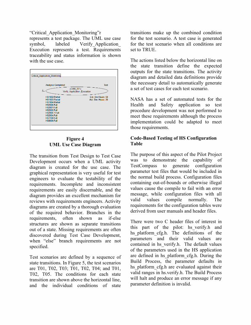
“Critical_Application_Monitoring”r represents a test package. The UML use case symbol, labeled Verify_Application_ Execution represents a test. Requirements traceability and status information is shown with the use case.
Figure 4 UML Use Case Diagram
The transition from Test Design to Test Case Development occurs when a UML activity diagram is created for the use case. The graphical representation is very useful for test engineers to evaluate the testability of the requirements. Incomplete and inconsistent requirements are easily discernable, and the diagram provides an excellent mechanism for reviews with requirements engineers. Activity diagrams are created by a thorough evaluation of the required behavior. Branches in the requirements, often shown as if-else structures are shown as separate transitions out of a state. Missing requirements are often discovered during Test Case Development, when “else” branch requirements are not specified.
Test scenarios are defined by a sequence of state transitions. In Figure 5, the test scenarios are T01, T02, T03; T01, T02, T04; and T01, T02, T05. The conditions for each state transition are shown above the horizontal line, and the individual conditions of state
transitions make up the combined condition for the test scenario. A test case is generated for the test scenario when all conditions are set to TRUE.
The actions listed below the horizontal line on the state transition define the expected outputs for the state transitions. The activity diagram and detailed data definitions provide the necessary detail to automatically generate a set of test cases for each test scenario.
NASA has a set of automated tests for the Health and Safety application so test procedure development was not performed to meet these requirements although the process implementation could be adapted to meet those requirements.
Code-Based Testing of HS Configuration Table
The purpose of this aspect of the Pilot Project was to demonstrate the capability of TestCompass to generate configuration parameter test files that would be included in the normal build process. Configuration files containing out-of-bounds or otherwise illegal values cause the compile to fail with an error message, while configuration files with all valid values compile normally. The requirements for the configuration tables were derived from user manuals and header files.
There were two C header files of interest in this part of the pilot: hs_verify.h and hs_platform_cfg.h. The definitions of the parameters and their valid values are contained in hs_verify.h. The default values of the parameters used in the HS application are defined in hs_platform_cfg.h. During the Build Process, the parameter defaults in hs_platform_cfg.h are evaluated against their valid ranges in hs.verify.h. The Build Process will halt and produce an error message if any parameter definition is invalid.

Figure 5 UML Activity Diagram
The first step in the development of the testing of the HS Configuration Table was to identify all of the configuration parameters contained in hs_verify.h. The file contained 26 parameters in the format of the example shown below.
The second step was to develop a UML model for each parameter. There are a total of 26 use case and activity diagrams, one for each tested parameter. The use case diagram for verifying the parameter HS_UTIL_AVERAGE_NUM_INTERVAL (HS-028) is shown in Figure 6.

Figure 6
UML Use Case Diagram The use case contains development status and traceability links to the requirements. There was a review of the requirements document to determine which requirements traced to configuration parameters. In Figure 6, there are three trace links to the high-level requirements (HS6008, HS6009, and
HS6010). HS-REQ-128 represents a trace link to the configuration file. Trace links to other high-level requirements appear in other use case diagrams.
The activity diagram for HS-028 is shown in Figure 7.
Figure 7 UML Activity Diagram
Table 1 shows the test cases generated for three test scenarios. The test case table contains test input values and expected output values.
The boundary analysis test development contains state transitions for “below lower bounds”, “above upper bounds”, and “in bounds”. Because they assume valid parameters, the high-level requirements only trace to in-bounds state transitions.
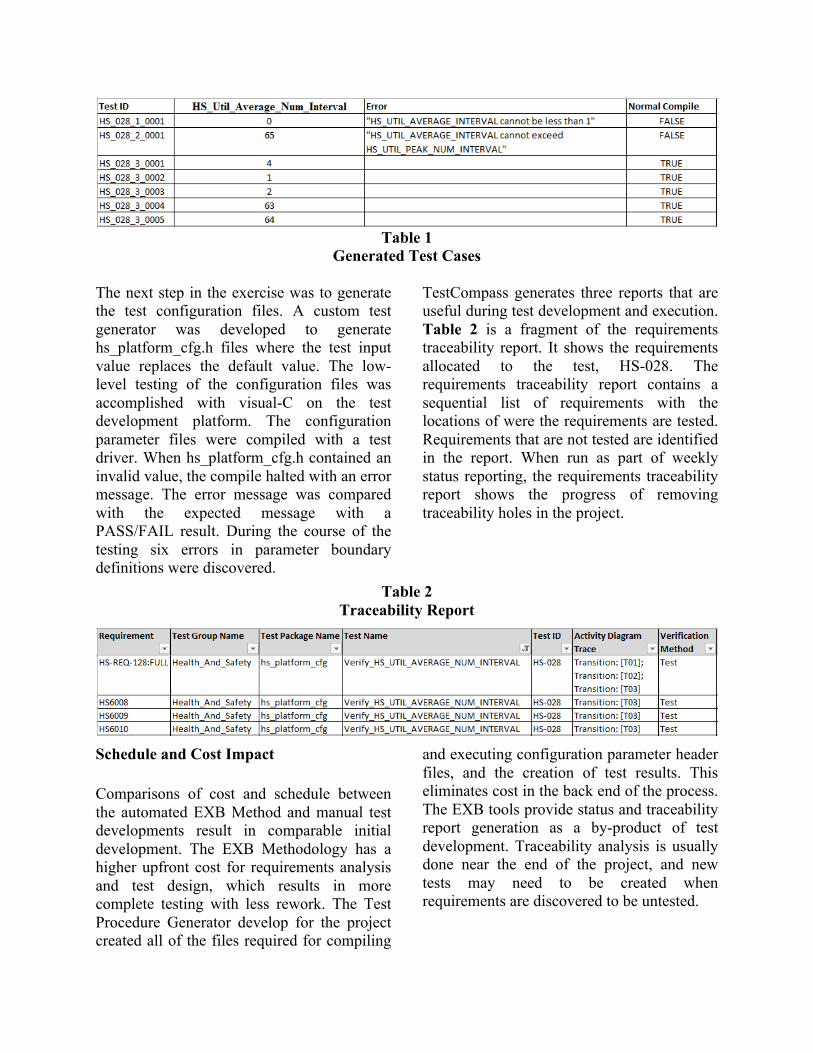
Table 1
Generated Test Cases The next step in the exercise was to generate the test configuration files. A custom test generator was developed to generate hs_platform_cfg.h files where the test input value replaces the default value. The low-level testing of the configuration files was accomplished with visual-C on the test development platform. The configuration parameter files were compiled with a test driver. When hs_platform_cfg.h contained an invalid value, the compile halted with an error message. The error message was compared with the expected message with a PASS/FAIL result. During the course of the testing six errors in parameter boundary definitions were discovered.
TestCompass generates three reports that are useful during test development and execution. Table 2 is a fragment of the requirements traceability report. It shows the requirements allocated to the test, HS-028. The requirements traceability report contains a sequential list of requirements with the locations of were the requirements are tested. Requirements that are not tested are identified in the report. When run as part of weekly status reporting, the requirements traceability report shows the progress of removing traceability holes in the project.
Table 2 Traceability Report
Schedule and Cost Impact
Comparisons of cost and schedule between the automated EXB Method and manual test developments result in comparable initial development. The EXB Methodology has a higher upfront cost for requirements analysis and test design, which results in more complete testing with less rework. The Test Procedure Generator develop for the project created all of the files required for compiling
and executing configuration parameter header files, and the creation of test results. This eliminates cost in the back end of the process. The EXB tools provide status and traceability report generation as a by-product of test development. Traceability analysis is usually done near the end of the project, and new tests may need to be created when requirements are discovered to be untested.

Table 3 shows the development time comparison for HS-028 between the EXB Methodology and typical manual development.
Table Testing Tine Comparisons
The process described resulted in about 21 hours saved for the initial development of 215 tests. Additional savings result when changes to the requirements occur and regression testing is required.
NASA Virtual System Evaluation
NASA provided EXB access to a virtual system, which, enables EXB to execute automated Build Tests in an off-target environment using STOL scripts. This facilitates higher level testing while reducing the cost and schedule required for the execution of Build Tests in the on-target test environment. The virtual test environment provides a capability to build and test an application, with modified hs_platform-cfg.h files, using existing STOL test procedures potentially reducing required system level testing.
Benefits Demonstrated By Joint Project
This NASA/EXB project demonstrated the advantages of applying a disciplined and automated process to requirement-based testing. This is particularly valuable for Safety Critical and Mission Critical applications with the following benefits:
• Requirement review and visual test case definition assure testable requirements
• Automation minimizes human involvement in regression testing and testing of modified requirements for new or existing applications
• Standard process/methodology increases the quality and repeatability of testing
• Automatically generated documentation provides consistent format and content
• An automation methodology that captures the test case and test procedure definitions in universal file formats capable of integration with various commercially available or proprietary automatic test environments, comprehensively testing the configuration space
• New and modified applications can be efficiently tested and verified using the virtual platform
• An automated methodology which, minimizes the cost of retesting new applications and/or new missions as the cFS software is repurposed.
Project Outcomes
The demonstration validated the configuration system of the cFS software and provided a repeatable platform on which to execute future testing. Along the way, EXB identified 6 minor issues through the testing process, tracked the progress of the effort and created a repeatable process to do high and low level testing in an automated environment.
Conclusion
The cFS architectural Layers 1 and 2 APIs shown in Figure 1 are now under a NASA-wide configuration control board. A goal of this board is to control the growth and evolution of the application environment which should allow for a sustainable “app store”. As the number of applications

increases the creation of new tests and the maintenance of application regression tests becomes increasingly more important. FSW will always require applications to be fully qualified.
In this effort, the verification methodology provides a well-defined repeatable process with artifacts suitable for long term maintenance. Therefore this approach may serve as a common cFS application verification method. Our next step is to continue to apply the verification method to additional cFS applications and to determine whether it will serve as the standard cFS verification methodology.