Automated Design of Digital Microfluids Lab-on-Chip
37
1 1 Automated Design of Digital Microfluidics Lab-on-Chip Krishnendu Chakrabarty Department of Electrical and Computer Engineering Duke University Durham, NC Connecting Biochemistry to Information Technology And Electronic Design Automation 2 Acknowledgments Acknowledgments • Students: Tianhao Zhang, Fei Su, William Hwang, Phil Paik, Tao Xu, Vijay Srinivasan, Yang Zhao • Post-docs, colleagues, and collaborators: Dr. Vamsee Pamula, Dr. Michael Pollock, Prof. Richard Fair, Dr. Jun Zeng (HP Labs), Dr. S. Krishnamoorthy (Baxter) • Duke University’s Microfluidics Research Lab (http://www.ee.duke.edu/research/microfluidics/) • Advanced Liquid Logic (http://www.liquid-logic.com/ ): Start-up company spun out off Duke University’s microfluidics research project
-
Upload
acmbangalore -
Category
Technology
-
view
2.132 -
download
0
description
Automated Design of Digital Microfluidics Lab-on-Chip Krishnendu Chakrabarty Department of Electrical and Computer Engineering Duke University Durham, NC Connecting Biochemistry to Information Technology And Electronic Design Automation Talk delivered at ACM Bangalore Distinguished Speaker Program Feb 2009
Transcript of Automated Design of Digital Microfluids Lab-on-Chip

1
1
Automated Design of Digital Microfluidics Lab-on-Chip
Krishnendu Chakrabarty
Department of Electrical and Computer EngineeringDuke UniversityDurham, NC
Connecting Biochemistry to Information TechnologyAnd Electronic Design Automation
2
AcknowledgmentsAcknowledgments• Students: Tianhao Zhang, Fei Su, William Hwang, Phil Paik, Tao Xu,
Vijay Srinivasan, Yang Zhao• Post-docs, colleagues, and collaborators: Dr. Vamsee Pamula, Dr.
Michael Pollock, Prof. Richard Fair, Dr. Jun Zeng (HP Labs), Dr. S. Krishnamoorthy (Baxter)
• Duke University’s Microfluidics Research Lab (http://www.ee.duke.edu/research/microfluidics/)
• Advanced Liquid Logic (http://www.liquid-logic.com/): Start-up company spun out off Duke University’s microfluidics research project

2
3
Motivation for LabMotivation for Lab--onon--ChipChip• Clinical diagnostics, e.g., healthcare for
premature infants, point-of-care diagnosis of diseases
• “Bio-smoke alarm”: environmental monitoring• Massive parallel DNA analysis, automated
drug discovery, protein crystallization
Conventional Biochemical Analyzer
ShrinkMicrofluidic Lab-
on-a-Chip
CLINICAL DIAGNOSTICAPPLICATION
20nl sample
Lab-on-a-chip forCLINICAL DIAGNOSTICS
Higher throughput, minimal human intervention, smaller sample/reagent consumption, highersensitivity, increased productivity
4
The Futility of Predicting ApplicationsThe Futility of Predicting ApplicationsKroemer’s Lemma of New Technology:
The principal applications of any sufficiently new and innovative technology have always been—and will continue to be—applications created by that technology.
Herbert Kroemer, Department of Electrical and Computer Engineering, University of California at Santa BarbaraNobel Prize winner for Physics, 2000

3
5
Tubes to Chips: Integrated CircuitsTubes to Chips: Integrated Circuits• Driven by Information Processing needs
IBM 701 calculator (1952)
IBM Power 5 IC(2004)
6
Tubes to Chips: Tubes to Chips: BioChipsBioChips• Driven by biomolecular analysis needs
Test tube analysis
BioMark™ Dynamic ArraysFluidigm

4
7
Why Do We Care?Why Do We Care?
2007
System Driver Beyond 2009: “Medical”
Intel Research Day 2007: Biochip prototypedemonstrated for point-of-care diagnostics andlab testing
8
Press Releases and News ItemsPress Releases and News Items
THE W
ALL STREET JO
URNAL

5
9
Why is BiochemistryWhy is Biochemistry--onon--aa--Chip Difficult?Chip Difficult?A
BC
A + B
A
BA + B
Synthesis
Analysis
Mixing
Reaction Separation
10
Why is BiochemistryWhy is Biochemistry--onon--aa--Chip Chip Difficult?Difficult?

6
11
By the way, what’s a biochip?It’s a miniature disposable for an
HTS - High-Throughput Screening -
(bio)analytical instrument
what does it do?Essentially the same operations you did in high school
chemistry class: dispensing,
mixing, detecting,
discarding,-just a lot cheaper and a lot faster than you did
12
Why do chips have to be small?
High-Throughput is why. If you do 106 assays in 10μl format,each time you do a reaction you’ll need 10 liters of reagents.
With the typical cost of biological reagents, even Big Pharma can’t afford this.
By the way, why High-Throughput?• Because you need a lot of raw data for many applications • Because, with the currently available technology, to produce
raw data that would keep a CPU busy for a few minutes ($0.1), you need a Ph.D. scientist and a couple of technicians for a month ($10,000)

7
13
Talk OutlineTalk Outline• Motivation• Technology Overview
– Microarrays– Continuous-flow microfluidics: channel-based lab-on-chip– “Digital” microfluidics: droplet-based lab-on-chip
• Overview of Fabrication Method• Design Automation Methods
– Synthesis and module placement– Droplet Routing– Pin-Constrained Design– Testing and Reconfiguration
• Conclusions
14
MicroarraysMicroarrays• DNA (or protein) microarray: piece of glass, plastic or silicon
substrate• Pieces of DNA (or antibodies) are affixed on a microscopic array• Affixed DNA (or antibodies) are known as probes• Only implement hybridization reaction
ATCGG
GATC
substrate
CATTGA
Hybridized array
Unhybridized array
DNA Sample
Laser
Optical ScanATCGG
GATC
substrate
CATTGA
TAGCC♦
GTAAC
♦T
CTAG♦

8
15
What are the main types of biochips?What are the main types of biochips?
Passive (array):all liquid handling functions are performed by
the instrument. The disposable is simply a
patterned substrate.
Active (lab-on-chip, μ-TAS):some active functions are performed by the
chip itself. These may include flow control,
pumping, separations where necessary, and
even detection.
16
Motivation for MicrofluidicsMotivation for Microfluidics
Test tubes
Robotics
MicrofluidicsAutomationIntegrationMiniaturization
AutomationIntegrationMiniaturization
AutomationIntegrationMiniaturization
9
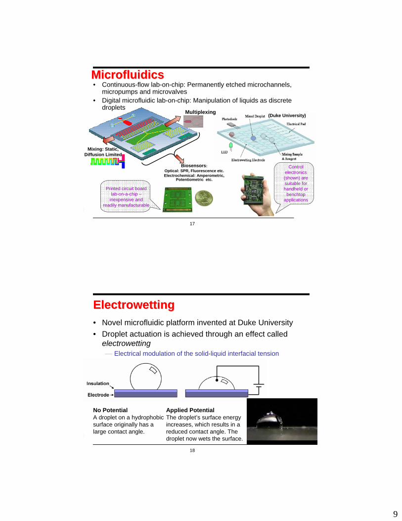
17
MicrofluidicsMicrofluidics• Continuous-flow lab-on-chip: Permanently etched microchannels,
micropumps and microvalves• Digital microfluidic lab-on-chip: Manipulation of liquids as discrete
droplets(Duke University)
Control electronics (shown) are suitable for handheld or
benchtopapplications
Printed circuit board lab-on-a-chip –
inexpensive and readily manufacturable
Biosensors: Optical: SPR, Fluorescence etc. Electrochemical: Amperometric,
Potentiometric etc.
Mixing: Static, Diffusion Limited
Multiplexing
18
ElectrowettingElectrowetting• Novel microfluidic platform invented at Duke University• Droplet actuation is achieved through an effect called
electrowetting⎯ Electrical modulation of the solid-liquid interfacial tension
No PotentialA droplet on a hydrophobic surface originally has a large contact angle.
Applied PotentialThe droplet’s surface energy increases, which results in a reduced contact angle. The droplet now wets the surface.

10
19
What is Digital Microfluidics?What is Digital Microfluidics?
• Discretizing the bottom electrode into multiple electrodes, we can achieve lateral droplet movement
Droplet Transport (Side View)Note: oil is typically used to fill between the top and bottom plates to prevent evaporation.
20
What is Digital Microfluidics?What is Digital Microfluidics?
Transport25 cm/s flow rates, order of magnitude
higher than continuous-flow
methods
For videos, go to www.ee.duke.edu/research/microfluidics
11
21
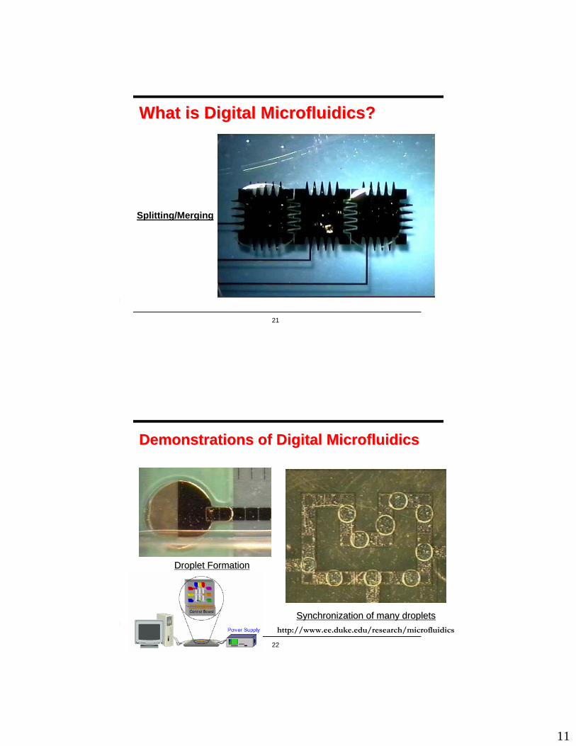
What is Digital Microfluidics?What is Digital Microfluidics?
Splitting/Merging
22
Demonstrations of Digital MicrofluidicsDemonstrations of Digital Microfluidics
Droplet FormationDroplet Formation
Synchronization of many dropletsSynchronization of many dropletshttp://www.ee.duke.edu/research/microfluidics

12
23
What is Digital Microfluidics?What is Digital Microfluidics?
Droplet Formation8 droplets in 3.6s
24
What is Digital Microfluidics?What is Digital Microfluidics?
Mixing

13
25
AdvantagesAdvantages• No bulky liquid pumps are required
– Electrowetting uses microwatts of power– Can be easily battery powered
• Standard low-cost fabrication methods can be used
– Continuous-flow systems use expensive lithographic techniques to create channels
– Digital microfluidic chips are possible using solely PCB processes
Droplet Transport on PCB (Isometric View)
26
An ExampleAn Example• Detection of lactate, glutamate and pyruvate has also been
demonstrated.• Biochip used for multiplexed in-vitro diagnostics on human
physiological fluids
Fabricated microfluidic array used for multiplexed biomedical assays

14
27
CapabilitiesCapabilities• Digital microfluidic lab-on-chip
MIXERSMIXERSTRANSPORTTRANSPORT DISPENSINGDISPENSING REACTORSREACTORS
INTEGRATE
Digital Microfluidic
Biochip
DETECTIONDETECTION
Basic microfluidic functions (transport, splitting, merging, and mixing) have already been demonstrated on a 2-D arrayHighly reconfigurable system
Protein crystallization chip(under development)
28
Advantages of Digital MicrofluidicsAdvantages of Digital Microfluidics
• Very accurate droplet volumes– Droplet sizes in the 1 nanoliter to several
microliter range; droplet dispensing volume variation ~1%
• Programmable, software-driven electronic control
– No moving parts, tubes, pumps or valves • More efficient use of samples and reagents
– No liquid is wasted priming channels• Extremely energy efficient
– Nanowatts of power per single step of actuation
• Development cycles are short, and assays can be implemented with software changes
• Compatible with live biologic and most other materials
• Pump fluids through channels• Must adapt assays to channel-
based format• Complex or multiplexed assays
become a plumber’s nightmare• Off-chip pumps and valves mean
large, expensive equipment and low reliability
• Expensive, time consuming, up-front investments required for most chip developments
• Designs are fixed in the development process
Other Microfluidic TechnologiesDigital Microfluidics
•Droplets moved in “virtual channels” defined by electrodes•Programmable electrodes directly control discrete droplet operations
Caliper Technologies’LabChip

15
29
Glass Chip Platform DevelopmentGlass Chip Platform DevelopmentTop Plate (Optional) (i.e. glass or plastic)
Gasket Layer (100 to 600 µm) (proprietary)
Hydrophobic Layer (50 nm) (i.e. Teflon dip coated)
Insulator Layer (1 to 25 µm) (i.e. parylene)
Patterned Metal on Substrate(i.e. chrome on glass via lift-off process)
Top plate is either glued or fixed in place by pressure
Contacts are made either through the top or bottom
Droplets are either dispensed by hand or formed from on-chip reservoirs
Chip Assembly
30
PCB Chip Platform DevelopmentPCB Chip Platform Development
Fabrication ProcessFlash Plating
(Copper)
PCB
• PCB Material – Mitsui BN300 – 64 mil• Top Metal Layer (Electrodes) – Cu – 15µm• Bottom Metal Layer (Contacts) – Cu – 15µm• Dielectric – LPI Soldermask – 25 µm• Via Hole Filling – Non-conductive Epoxy• Hydrophobic Layer – Teflon AF – 0.05 to 1.0 µm• Gasket (spacer) – Dry Film Soldermask (Vacrel 8140) – 4 mils (~95µm after processing)
Gasket Layer(Dry Soldermask)
Hydrophobic Layer(Teflon AF)
Dielectric(LPI Soldermask)
Top Metal Layer(Copper)
Bottom Metal Layer(Copper)
Via Hole Filling(Non Conductive Epoxy)

16
31
ComputerComputer--Aided Design: VisionAided Design: Vision• Automate labor-intensive tasks, reduce burden on chip users
– Map bioassays to a fabricated chip: schedule fluidic operations,determine droplet flow pathways, configure fluidic modules dynamically, etc.
– Monitor the chip for defects that require remapping of bioassays• Role of computer-aided design (CAD) tools
– Reduce setup time associated with the use of these chips– Allow automatic reconfiguration of a faulty chip and remap the
remaining steps of bioassay. – Develop capabilities that mirror compiler and operating system support
provided to software programmers– Obviate the need for tedious remapping of assays to the chip by hand
for each target application.• Similar to an FPGA? Logic Interconnects
32
CAD = ?CAD = ?
cad n. An unprincipled, ungentlemanly person
CAD abbr. Computer-Aided Design
Better to be in CAD than to be a cad?

17
33
The Road Not TakenThe Road Not Taken……I shall be telling this with a sighSomewhere ages and ages hence:Two roads diverged in a wood, and I-I took the one less traveled by,And that has made all the difference.
Robert Frost, The Road Not Taken
Agilent’s Protein LabChip Nanogen’s NanoChip™
Microelectronic Array Cartridge
i-STAT Biodiagnostic μ-system
34
Similar to Concurrency in a PC!Similar to Concurrency in a PC!
January 28, 2007 Prof. Radu Marculescu Attn: Outstanding Ph.D. Dissertation Award Carnegie Mellon University Department of Electrical and Computer Engineering 5000 Forbes Avenue Pittsburgh PA 15213-3890
Dear Prof. Marculescu:
I am very pleased to write this letter of nomination for Dr. Fei Su for the ACOutstanding Ph.D. Dissertation Award in Electronic Design Automation. received his Ph.D. degree from Duke University in May 2006 and his thesis wowas carried out under my supervision.
Fei’s PhD dissertation is titled “Synthesis, Testing, and ReconfiguratTechniques for Digital Microfluidic Biochips”. It is focused on design automatiand test methods for emerging lab-on-a-chip devices that rely on the principleelectrowetting-on-dielectric. By exploiting the reconfigurability inherent droplet-based “digital” microfluidics, these devices are revolutionizing a wrange of applications, such as high-throughput sequencing, paraimmunoassays, blood chemistry for clinical diagnostics, DNA sequencing, aenvironmental toxicity monitoring.
Microsystems for biomedical and sensing applications are often referred to lab-on-a-chip or biochips. These are typically centimeter-sized chips, with on-chcomponents having micrometer feature lengths. These components are createdIC fabrication technology (surface or bulk micro-machining), and they are diverse functionality. Just as bioscience is sometimes called “wet” science, tapplication of biochips relies primarily on its ability to work with fluids throuits on-chip components. Biochemical samples are placed on the biochip inliquid form. A pre-programmed analysis is then carried out automatically andparallel. Miniaturization enables minute sample volume, thus it speeds chemical reactions and analytical detection; automation and parallelization mait possible to carry out a massive number of different tests simultaneously. Thecharacteristics, especially the delivery of results for a large number of tests witha short amount of time, are especially relevant for clinical diagnostienvironmental monitoring, and bio-defense applications.
Digital microfluidics has heralded the second (and remarkably advancgeneration of biochips. It utilizes tiny droplets as on-chip chemical compoucarriers. An on-chip array of electrodes that are individually addressable throuCMOS electronics can manipulate each droplet electrically. A set of programmaCMOS instructions can induce the merging of two droplets. Such mergoperations constitute the key operations in on-chip chemical reactions. Multi-s
The operating system manages complexity, allows multi-tasking!

18
35
Constraints:Area <…Delay <…
Top-down design method
System Level
…..Module Level
….. Gate Level
…..
Circuit Level
Gate Level
Module Level
VLSI chip wanted
Bottom-up design method
Design MethodologyDesign Methodology• VLSI design
…..
Circuit Level
System LevelIf constraints are not met
Re-design
36
Biochip wanted
Bottom-up design method
If constraints are not met
Re-design all sub-blocks !
Biochip Design Methodology Biochip Design Methodology • Bottom-up vs. top-down biochip design
Component 1 designed and verified
Component ndesigned and verified
Anticipated to be needed
…..
…Module 1
designed and verifiedModule m
designed and verified
Anticipated to be needed
Biochip designedBiochip wanted
Constraints
Biochip designed
Module 1 designed
Module m designed
Constraints Constraints
…..
Component 1 designed
Component ndesigned
…..
ConstraintsConstraints
Top-down design method
19
37
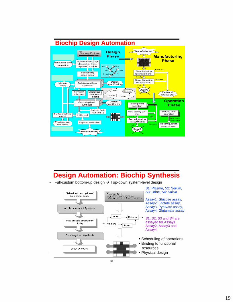
Biochip Design AutomationBiochip Design Automation
38
Design Automation: Biochip SynthesisDesign Automation: Biochip Synthesis• Full-custom bottom-up design Top-down system-level design
Scheduling of operationsBinding to functionalresourcesPhysical design
S1: Plasma, S2: Serum,S3: Urine, S4: Saliva
Assay1: Glucose assay, Assay2: Lactate assay, Assay3: Pyruvate assay, Assay4: Glutamate assay
S1, S2, S3 and S4 are assayed for Assay1, Assay2, Assay3 and Assay4.

20
39
Sequencing Graph ModelSequencing Graph Model
Sequencing graph model for multiplexed bioassays
40
Mathematical Programming Model Mathematical Programming Model
• First define a binary variable
⎩⎨⎧
=ijX 1 if operation vi starts at time slot j.
0 otherwiseStarting time of operation vi :
∑=
×=T
jiji XjSt
1
Completion time of operation:C = max {Sti + d(vi) : vi ∈D1, …, Dn}
Objective function: minimize C
Dependency constraintsStj ≥ Sti + d(vi) if there is a dependency
between vi and vj
Resource constraintsReservoirs/dispensing ports
Nr reservoirs/dispensing ports assigned to each type of fluid (Nr = 1)
… : 1≤ j≤ T,11:
∑∈
≤Ivi
iji
X ∑+∈
≤nmi Ivi
ijX:
1
Reconfigurable mixers and storage units
Nmixer(j) + 0.25 Nmemory(j) ≤ Na 1 ≤ j ≤ T
Optical detectorsNd detectors are assigned to each
bioassay (Nd = 1)
,11: )(
∑ ∑∈ −=
≤Dvi
j
vdjlij
i i
X ∑ ∑∈ −=
≤1: )(
1ni iDvi
j
vdjlijX… 1≤ j≤ T
Objective Constraints

21
41
Physical Design: Module PlacementPhysical Design: Module Placement• Placement determines the locations of each module on the
microfluidic array in order to optimize some design metrics • High dynamic reconfigurability: module placement 3-D
packing modified 2-D packing
Reduction from 3_D placement to a modified 2-D placement
42
Unified Synthesis MethodologyUnified Synthesis Methodology

22
43
Protein Assay: Dilution StepsProtein Assay: Dilution StepsSequencing graph model
• Maximum array area: 10x10
• Maximum number of optical detectors: 4
• Reservoir number: 1 for sample; 2 for buffer; 2 for reagent; 1 for waste
• Maximum bioassay time: 400 s
44
Synthesis ResultsSynthesis Results
Bioassay completion time T: 363 seconds
Biochip array: 9x9 array

23
45
Synthesis Results (Cont.)Synthesis Results (Cont.)• Defect tolerance
Bioassay completion time T: 385 seconds (6% increase)
46
Droplet RoutingDroplet Routing• A key physical design problem for digital microfluidic
biochips• Given the results from architectural-level synthesis and
module placement:– Determine droplet pathways using the available cells in the
microfluidic array; these routes are used to transport droplets between modules, or between modules and fluidic I/O ports (i.e., boundary on-chip reservoirs)
• To find droplet routes with minimum lengths– Analogous to the minimization of the total wirelength in VLSI
routing• Need to satisfy critical constraints
– A set of fluidic constraints– Timing constraints: (the delay for each droplet route does not
exceed some maximum value, e.g., 10% of a time-slot used in scheduling)

24
47
Static fluidic constraintStatic fluidic constraint Dynamic fluidic constraintsDynamic fluidic constraints
Fluidic ConstraintsFluidic Constraints
Rule #1: |Xi(t+1) − Xj(t+1)| ≥ 2 or |Yi(t+1) − Yj(t+1)| ≥ 2, i.e., their new locations are not adjacent to each other.
• Assume two given droplets as Diand Dj, and let Xi(t) and Yi(t) denote the location of Di at time t
How to select the admissible locations at time t +1?
Rule #2: |Xi(t+1) − Xj(t)| ≥ 2 or |Yi(t+1) − Yj(t)| ≥ 2, i.e., the activated cell for Di cannot be adjacent to Dj.
Rule #3: |Xi(t) − Xj(t+1)| ≥ 2 or |Yi(t) − Yj(t+1)| ≥ 2.
Directly adjacent
Diagonally adjacent
48
Experimental VerificationExperimental Verification
(a) Experimental verification of Rule #1: droplets begin on electrodes 1 and 4; (b) Electrodes 2 and 3 are activated, and 1 and 4 deactivated; (c) Merged droplet.
(a) Experimental verification of Rule #2: droplets begin on electrodes 2 and 4; (b) Electrodes 1 and 3 are activated, and 2 and 4 deactivated.

25
49
Experimental Verification (Cont.)Experimental Verification (Cont.)
(a) Experimental verification of Rule #3: droplets begin on electrodes 4 and 7; (b) Electrodes 3 and 6 are activated, and 4 and 7 deactivated; (c) Merged droplet.
• To demonstrate that adherence to Rule #1 is not sufficient to prevent merging. Both Rule #2 and Rule #3 must also be satisfied during droplet routing.
• These rules are not only used for rule checking, but they can also provide guidelines to modify droplet motion (e.g., force some droplets to remain stationary in a time-slot) to avoid constraint violation if necessary
50
Design of PinDesign of Pin--Constrained BiochipsConstrained BiochipsDirect Addressing• Each electrode connected to an independent pin
• For large arrays (e.g., > 100 x 100 electrodes)– Too many control pins ⇒ high fabrication cost– Wiring plan not available
PCB design: 250 um via hole, 500 um x 500 um electrode
Via HolesVia HolesWiresWires
Nevertheless, we need high-throughput and low cost:DNA sequencing (106 base pairs), Protein crystallization (103 candidate conditions)
Disposable, marketability, $1 per chip

26
51
PinPin--Constrained Biochip DesignConstrained Biochip Design• Cross-referencing
Orthogonally placed pins on top and bottom plates
Advantagek = n x m pins n + m pins for an n x m microfluidic array
DisadvantageSuffer from electrode interference
52
Electrode InterferenceElectrode Interference• Unintentional Electrode Actuation
Selected column and row pins may intersect at multiple electrodes
• Unintentional Droplet Manipulation
1 2 3 4 5 6 7 8 9 10
1 2 3 4 5 6 7 8 910
3
2
1
destination cellsdestination cells
Unintentional Unintentional destination cellsdestination cells

27
53
Efficient (Concurrent) Droplet Efficient (Concurrent) Droplet ManipulationManipulation• Goal: Improve droplet manipulation concurrency on
cross-referencing-based biochips.
9 steps needed if 9 steps needed if moving one droplet moving one droplet at a time (too slow)at a time (too slow)
54
Efficient Droplet ManipulationEfficient Droplet Manipulation• Observation
– Droplet manipulations whose destination cells belongs to the same column/row can be carried out without electrode interferences.
destination cellsdestination cells
94

28
55
Efficient Droplet ManipulationEfficient Droplet Manipulation• Methodology
– Group droplet manipulations according to their destination cells– All manipulations in a group can be executed simultaneously
The goal is to find an optimal grouping plan which results in the minimum number of groups.
56
Efficient Droplet ManipulationEfficient Droplet Manipulation• Problem formulation
Destination cells NodesDestination cells in one column/row a clique Grouping Clique partitioningOptimal grouping Minimal clique-partitioning (NP-Complete)

29
57
Broadcast ElectrodeBroadcast Electrode--AddressingAddressing• Observation
“Don’t-Cares” in Electrode-Actuation SequencesElectrode control inputs: 3 values“1” –- activated “0” –- deactivated“x” –- can be either “1” or “0”Therefore, activation sequences can be combined by interpreting “x” Floating electrodeFloating electrode
Example: A droplet routed counterclockwise on a loop of electrodes Corresponding electrode activation
sequences
58
Solution Based on Clique PartitioningSolution Based on Clique Partitioning• Idea
– Combining compatible sequences to reduce # of control pins
• Clique partitioning based methodElectrodes NodesElectrodes with compatible activation sequences a clique Optimal combination Minimal clique-partitioning

30
59
Solution Based on Clique PartitioningSolution Based on Clique Partitioning
Bioassay synthesis results
Scheduling & droplet routing plan
Activation sequence for each electrode Undirected graph
Extract
Calculate
Map
Clique partitioning Result
Generate
Reduced number of control pins
Combine
60
Application to a Multiplexed BioassayApplication to a Multiplexed Bioassay
A biochip target execution of a multiplexed assay
Sequencing graph model of the multiplexed assay
• A glucose assay and a lactate assay based on colorimetric enzymatic reactions • 4 pairs of droplets – {S1, R1}, {S1, R2}, {S2, R1}, {S2, R2}, are mixed in the mixer in
the middle of the chip, the mixed droplets are routed to the detector for analysis

31
61
Results Results
303525# of control pins
Cross-referencing-based method
Array-partitioning-based method
Broadcast addressing
Addressing methods
Comparison of bioassay completion time using different addressing methods
73 s 73 s
132 s
62
Application to MultiApplication to Multi--functional functional ChipChip• Multi-functional Chip
– biochips targeting the execution of a set of (multiple) predetermined bioassays
• Application of Broadcast Addressing to Multi-functional Chips Key idea: treat the union of the target bioassays as a single bioassay– Collect droplet routing and schedule information for each target
bioassay– Calculate activation sequences for each bioassay – Merge the activation sequences from the different assays and obtain a
collective activation sequence for each electrode – Note that merging of activation sequences can be carried out in any
arbitrarily-chosen order

32
63
Addressing Results Addressing Results
Sequencing graph model of the multiplexed assay
Sequencing graph model of protein dilution
Sequencing graph model of Polymerase Chain Reaction (PCR)
64
Addressing Results Addressing Results Chip layout and broadcast-addressing result for the multi-functional chip for
1. Multiplexed assay2. PCR assay 3. Protein dilution assay
Total number of control pins: 37
The addition of two assays to the biochip for the multiplexed assay leads to only 13 extra control pins

33
65
ReconfigurabilityReconfigurability• Common microfluidic operations
– Different modules with different performance levels (e.g., several mixers for mixing)
– Reconfiguration by changing the control voltages of the corresponding electrodes
66
Reconfiguration and Graceful DegradationReconfiguration and Graceful Degradation• Reconfigure the faulty module
– Avoid defects (faulty cells)• Reconfiguration: bypass faulty cells
– No spare cells; use fault-free unused cells• Defect tolerance in design procedure (increase in design complexity)
– Incorporate physical redundancy in the array• Spare cells replace defective cells (local reconfiguration,
application-independent)•

34
67
Testing of Digital Microfluidics BiochipsTesting of Digital Microfluidics BiochipsStimuli: Test droplets; Response: Presence/absence of droplets
Fragmentation of droplets and their motion is prevented
Dielectric islands(islands of Teflon coating)
1Non-uniform dielectric layer
Coatingfailure
Droplet transportation without activation voltage
Pressure gradient (net static pressure in some direction)
1Misalignment of parallel plates (electrodes and ground plane)
Excessive mechanical force applied to chip
Unintentional droplet operations or stuck droplets
Electrode-stuck-on (electrode remains constantly activated)
1Irreversible charge concentration on electrode
Electrodeactuation for excessiveduration
Droplet undergoes electrolysis; preventsfurthertransportation
Droplet-electrode short (short between the droplet and the electrode)
1Dielectric breakdown
Excessiveactuationvoltageapplied toelectrode
Observableerror
Faultmodel
No.cells
Defect type
Cause of defect
68
More Defects in Digital Microfluidic BiochipsMore Defects in Digital Microfluidic BiochipsObservableerror
Faultmodel
No.cells
Defect type
Cause of defect
Assay results are outside the range of possible outcomes
Contamination
Droplet transportation is impeded.
Resistive open at electrode
1Sample residue on electrode surface
Protein absorption during bioassay
Electrode short2Particle connects two adjacent electrodes
Particle contamination or liquid residue
A droplet resides in the middle of the two shorted electrodes, and its transport cannot be achieved
Electrode short (short between electrodes)
2Metal connectionbetween adjacent electrodes
Failure to activate theelectrode for droplettransportation
Electrode open (actuation not possible)
1Broken wire to Control source
Failure of droplet transportation
Floating droplets (droplet not anchored )
1Grounding failure
Abnormalmetal layerdepositionand etchvariationduringfabrication

35
69
Electrical Detection MechanismElectrical Detection Mechanism• Minimally invasive• Easy to implement (alleviate
the need for external devices)• Fault effect should be
unambiguous
Capacitive changes reflected in electrical signals (Fluidic domain to electrical domain)• If there is a droplet,
output=1; otherwise, output=0
• Fault-free : there is a droplet between sink electrodes Faulty: there is no droplet.
Electrically control and track test stimuli droplets
Droplet
150 pF
74C14
5 K
1N914
1N52315.1V
1N914
Gnd
+ 5 V
10 KOutputPeriodic
square waveform
70
DefectDefect--Oriented Experiment Oriented Experiment • Understand the impact of certain defects on droplet flow, e.g., for
short-circuit between two electrodes• Experimental Setup
– To evaluate the effect of an electrode short on microfluidic behavior

36
71
ConclusionsConclusions• Digital microfluidics offers a viable platform for lab-on-chip for clinical
diagnostics and biomolecular recognition• Design automation challenges
– Automated synthesis: scheduling, resource binding, module placement; droplet routing; testing and reconfiguration
• Bridge between different research communities: bioMEMS, microfluidics, electronics CAD and chip design, biochemistry
• Growing interest in the electronics CAD community– Special session on biochips at CODES+ISSS’2005 (appears in CFP now)– Special issue on biochips in IEEE Transactions on CAD (Feb 2006), IEEE Design &
Test of Computers (Jan/Feb’07)– Workshop on biochips at DATE’06– Tutorials on digital microfluidic lab-on-chip at DATE’07, ISCAS’08, VDAT 2007;
embedded tutorial at VLSI Design 2005– Other notable activities in digital microfluidics: University of California at Los
Angeles, University of Toronto, Drexel University, IMEC (Belgium), Freiburg (Germany), Philips (Netherlands), Fraunhofer Institute (Berlin, Germany), and many more….
72

37
73
2006 X, 406 p. HardcoverISBN-10: 1-4020-5122-0, ISBN-13: 978-1-4020-5122-7
ISBN: 0849390095Publication Date: 10/5/2006, 248 p.