
Autodesk Inventor® Part Modeling: The First Step - AUGI · 2 Objectives Take a good look at the...
18
Walt Disney World Swan and Dolphin Resort Orlando, Florida 12/1/2005 - 8:00 am - 11:30 am Room:Macaw 1/2 (Swan) Autodesk Inventor® Part Modeling: The First Step Lofts, tangents, and bores! Oh my! No need to fear Inventor part modeling. We'll show you everything you need to know to be the hero back at the office. This class will demonstrate most of the sketch tools and part features in Autodesk Inventor, and show logical techniques and guiding principles that can help you create accurate parametric parts that will behave themselves in your assemblies. Proper sketch and part modeling is the foundation for Inventor assemblies and for capturing the proper design intent. This class will benefit AutoCAD 3D users and newcomers to Inventor. Also, many current Inventor users focus on assembly modeling at the expense of developing part modeling expertise MA41-2 About the Speaker: Anthony Dudek - A.F.Dudek & Associates, Inc. Thomas Short, P.E. and One of Tony's main ideas overarching his 20-year-long career in engineering is that designing in 3D is a smarter and faster way to work. His philosophy is "Whatever it takes, do it right the first time." Tools like Autodesk Inventor can help achieve that goal. He believes that the engineering landscape in America has changed from an internal, ownership environment to an overextended and outsourced managed environment. Within this context, we are challenged to continue to deliver more quality in less time. This is the challenge of our generation of technology workers. The future is very promising with new technologies and methods being implemented every day. This will be Tony's 11th year at Autodesk University. [email protected] Tom is a mechanical engineer registered as a professional in Michigan. He has taught and consulted on AutoCAD, Autodesk Inventor, and Autodesk Mechanical Desktop for many years in the U.S. and other countries. At Munro & Associates, Inc., Tom is a consultant on Lean Design, and has worked with a variety of companies helping them improve their designs for simplicity and ease of assembly. He is also an author with books on Inventor and Mechanical Desktop. Tom has presented at every Autodesk University since its inception 12 years ago.
Transcript of Autodesk Inventor® Part Modeling: The First Step - AUGI · 2 Objectives Take a good look at the...
Walt Disney World Swan and Dolphin ResortOrlando, Florida
12/1/2005 - 8:00 am - 11:30 am Room:Macaw 1/2 (Swan)
Autodesk Inventor® Part Modeling: The First Step
Lofts, tangents, and bores! Oh my! No need to fear Inventor part modeling. We'll show you everything you need to know to be the hero back at the office. This class will demonstrate most of the sketch tools and part features in Autodesk Inventor, and show logical techniques and guiding principles that can help you create accurate parametric parts that will behave themselves in your assemblies. Proper sketch and part modeling is the foundation for Inventor assemblies and for capturing the proper design intent. This class will benefit AutoCAD 3D users and newcomers to Inventor. Also, many current Inventor users focus on assembly modeling at the expense of developing part modeling expertise
MA41-2
About the Speaker:
Anthony Dudek - A.F.Dudek & Associates, Inc.Thomas Short, P.E.and
One of Tony's main ideas overarching his 20-year-long career in engineering is that designing in 3D is a smarter and faster way to work. His philosophy is "Whatever it takes, do it right the first time." Tools like Autodesk Inventor can help achieve that goal. He believes that the engineering landscape in America has changed from an internal, ownership environment to an overextended and outsourced managed environment. Within this context, we are challenged to continue to deliver more quality in less time. This is the challenge of our generation of technology workers. The future is very promising with new technologies and methods being implemented every day. This will be Tony's 11th year at Autodesk [email protected]
Tom is a mechanical engineer registered as a professional in Michigan. He has taught and consulted on AutoCAD, Autodesk Inventor, and Autodesk Mechanical Desktop for many years in the U.S. and other countries. At Munro & Associates, Inc., Tom is a consultant on Lean Design, and has worked with a variety of companies helping them improve their designs for simplicity and ease of assembly. He is also an author with books on Inventor and Mechanical Desktop. Tom has presented at every Autodesk University since its inception 12 years ago.

About the Speakers: One of Tony's main ideas overarching his 20-year-long career in engineering is that designing in 3D is a smarter and faster way to work. His philosophy is "Whatever it takes, do it right the first time." Tools like Autodesk Inventor can help achieve that goal. He believes that the engineering landscape in America has changed from an internal, ownership environment to an overextended and outsourced managed environment. Within this context, we are challenged to continue to deliver more quality in less time. This is the challenge of our generation of technology workers. The future is very promising with new technologies and methods being implemented every day. This will be Tony's 11th year at Autodesk University.
Tom Short is a mechanical engineer registered as a professional in Michigan. He has taught and consulted on AutoCAD, Autodesk Inventor, and Autodesk Mechanical Desktop for many years in the U.S. and other countries. At Munro & Associates, Inc., Tom is a consultant on Lean Design, and has worked with a variety of companies helping them improve their designs for simplicity and ease of assembly. He is also an author with books on Inventor and Mechanical Desktop. Tom has presented at every Autodesk University since its inception 12 years ago.
November 28 – December 1, 2005 • Orlando, Florida
Autodesk Inventor ® Part Modeling: The First Step Anthony Dudek – A.F.Dudek & Assoc., Inc.
Tom Short - Munro & Assoc., Inc.
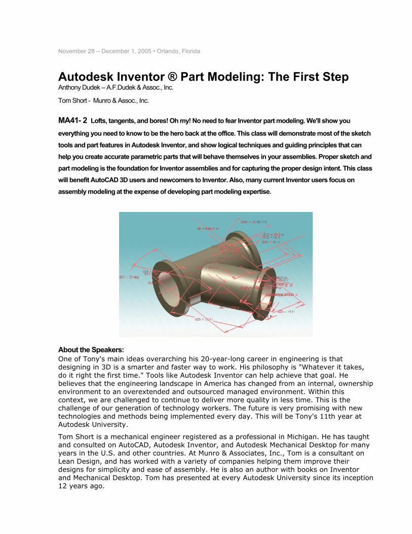
MA41- 2 Lofts, tangents, and bores! Oh my! No need to fear Inventor part modeling. We'll show you
everything you need to know to be the hero back at the office. This class will demonstrate most of the sketch tools and part features in Autodesk Inventor, and show logical techniques and guiding principles that can help you create accurate parametric parts that will behave themselves in your assemblies. Proper sketch and part modeling is the foundation for Inventor assemblies and for capturing the proper design intent. This class will benefit AutoCAD 3D users and newcomers to Inventor. Also, many current Inventor users focus on assembly modeling at the expense of developing part modeling expertise.
2
Objectives
Take a good look at the powerful tools available to assist you in designing incredible parts in Autodesk Inventor.
Gain more Inventor power from these techniques to make you famous!
Acquire a better understanding of parametric design methodology inside the latest release of Autodesk Inventor.
Outline
8:00 – 8:15 15 min. Introductions – Class Objectives
8:15 – 8:45 30 min. Sketching and Control
8:45 – 9:30 45 min. Effective Part Modeling
9:30 – 9:45 15 min. Take a Break
9:45 – 10:30 45 min. Sweeps and Lofts, etc.
10:30 – 11:20 50 min. Advanced Part Modeling – use Parametrics
11:20 – 11:30 10 min. Summary - Question & Answer
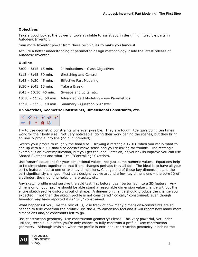
On Sketches, Geometric Constraints, Dimensional Constraints, etc.
Try to use geometric constraints wherever possible. They are tough little guys doing ten times work for their body size. Not very noticeable, doing their work behind the scenes, but they bring an unruly profile into line (no pun intended).
Sketch your profile to roughly the final size. Drawing a rectangle 12 X 6 when you really want to end up with a 2 X 1 final size doesn’t make sense and you’re asking for trouble. The rectangle example is an oversimplification, but you get the idea. Later on, as your skills improve you can use Shared Sketches and what I call “Controlling” Sketches.
Use “smart” equations for your dimensional values, not just dumb numeric values. Equations help to tie dimensions together so that if one changes perhaps they all do! The ideal is to have all your part’s features tied to one or two key dimensions. Change one of those key dimensions and the part significantly changes. Most part designs evolve around a few key dimensions – the bore ID of a cylinder, the mounting holes on a bracket, etc.
Any sketch profile must survive the acid test first before it can be turned into a 3D feature. Any dimension on your profile should be able stand a reasonable dimension value change without the entire sketch profile distorting out of shape. A dimension change should produce the change you expected, if not then the sketch profile is not considered “logically” constrained; even though Inventor may have reported it as “fully” constrained.
What happens if you, like the rest of us, lose track of how many dimensions/constraints are still needed to fully constrain the profile? Use the Auto-dimension tool and it will report how many more dimensions and/or constraints left to go.
Use construction geometry! Use construction geometry! Please! This very powerful, yet under utilized, technique is often you’re only chance to fully constrain a profile. Use construction geometry. Although invisible when the profile is extruded, construction geometry is behind the
Autodesk Inventor® Part Modeling: The First Step
3
scenes doing its job. Construction geometry not only has its uses in sketch profiles, but also in assemblies.
The Sketch Doctor isn’t always right! Many of you have probably ran into the infuriating Catch-22 type situation wherein the Sketch Doctor says that a sketch is missing coincident constraints at some vertices. However, at the same time he is also reporting that those same vertices have redundant coincident constraints! My best advice – ignore him in this situation.
Inventor Features Tutorial
We’re going to do a tutorial to demonstrate some of Inventor’s Part Modeling capabilities. No dataset parts are required – this will start from a new Part.
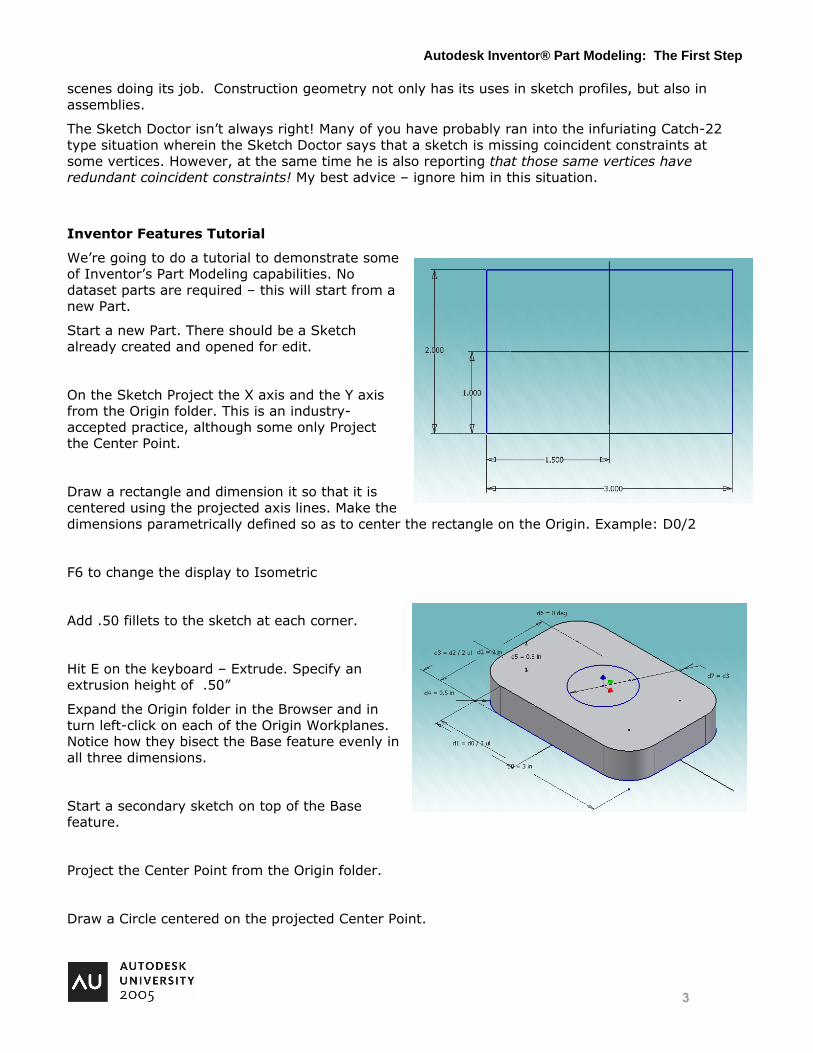
Start a new Part. There should be a Sketch already created and opened for edit.
On the Sketch Project the X axis and the Y axis from the Origin folder. This is an industry-accepted practice, although some only Project the Center Point.
Draw a rectangle and dimension it so that it is centered using the projected axis lines. Make the dimensions parametrically defined so as to center the rectangle on the Origin. Example: D0/2
F6 to change the display to Isometric
Add .50 fillets to the sketch at each corner.
Hit E on the keyboard – Extrude. Specify an extrusion height of .50”
Expand the Origin folder in the Browser and in turn left-click on each of the Origin Workplanes. Notice how they bisect the Base feature evenly in all three dimensions.
Start a secondary sketch on top of the Base feature.
Project the Center Point from the Origin folder.
Draw a Circle centered on the projected Center Point.
Autodesk Inventor® Part Modeling: The First Step
4
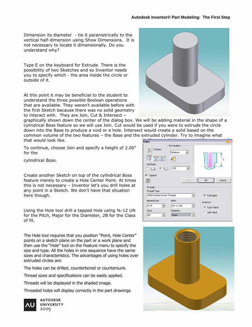
Dimension its diameter - tie it parametrically to the vertical half-dimension using Show Dimensions. It is not necessary to locate it dimensionally. Do you understand why?
Type E on the keyboard for Extrude. There is the possibility of two Sketches and so Inventor needs you to specify which - the area inside the circle or outside of it.
At this point it may be beneficial to the student to understand the three possible Boolean operations that are available. They weren’t available before with the first Sketch because there was no solid geometry to interact with. They are Join, Cut & Intersect – graphically shown down the center of the dialog box. We will be adding material in the shape of a cylindrical Boss feature so we will use Join. Cut would be used if you were to extrude the circle down into the Base to produce a void or a hole. Intersect would create a solid based on the common volume of the two features – the Base and the extruded cylinder. Try to imagine what that would look like.
To continue, choose Join and specify a height of 2.00” for the
cylindrical Boss.
Create another Sketch on top of the cylindrical Boss feature merely to create a Hole Center Point. At times this is not necessary – Inventor let’s you drill holes at any point in a Sketch. We don’t have that situation here though.
Using the Hole tool drill a tapped Hole using ¾-12 UN for the Pitch, Major for the Diameter, 2B for the Class of fit.
The Hole tool requires that you position “Point, Hole Center” points on a sketch plane on the part or a work plane and then use the “Hole” tool on the Feature menu to specify the size and type. All the holes in one sequence have the same sizes and characteristics. The advantages of using holes over extruded circles are:
The holes can be drilled, counterbored or countersunk.
Thread sizes and specifications can be easily applied.
Threads will be displayed in the shaded image.
Threaded holes will display correctly in the part drawings.
Autodesk Inventor® Part Modeling: The First Step

5
“Hole Notes” can be automatically applied to the part drawings.
“Hole Tables” can be created in the part drawings.
There is a Thread tool also. This is meant for internal / external threads on extruded cylinders that were not created with the Hole tool.
Using the Chamfer tool put a .06” Chamfer on the opening edge of the tapped Hole.
Using the Color Style droplist on the right-hand side of the Standard toolbar change to Metal Brass or Beige Light.
Select the YZ Plane of the Origin folder in the Browser and key ‘S’ on the keyboard. The F7 function key will slice the part visually with the Sketch Plane. Successive use of the F7 key simply toggles the effect on and off. F4 Rotate the screen to look at the other side of the Part and use F7 again. Notice that the visual slice is viewpoint dependent. Select the Sketch in the Browser and hit Page Up on the keyboard to get a plan display of the Sketch. Project the top edge of the Base (left side). Draw a line from touching the projected geometry and up and to the right. Dimension it from the edge (.01875”) and at a 60 deg. angle. Not necessary to fully constrain it. (refer to Figure)
Use the Rib tool to create a Rib feature. Use the midplane option and make it (.125”) thick. Use the Direction button to specify that the Rib should extrude down towards the body of the Part. A visual cue will
help you. It should not be necessary to Extend the Rib feature so that it meets the solid geometry of the Part – Inventor will assume that.
Select the Rib feature in the Browser by left-clicking on it. Choose the Circular Pattern tool from the Tool Panel and specify the cylindrical Boss feature as the axis for the Pattern. Choose a count of 4 for the Ribs and an angle of 360 to fill with the Pattern. Expand the << button and examine the Methods. The Creation Method dictates whether the members of the Pattern will all be alike or will adjust to conform to the Part’s perhaps changing geometry. The Positioning Method determines whether the angle value
Autodesk Inventor® Part Modeling: The First Step
6
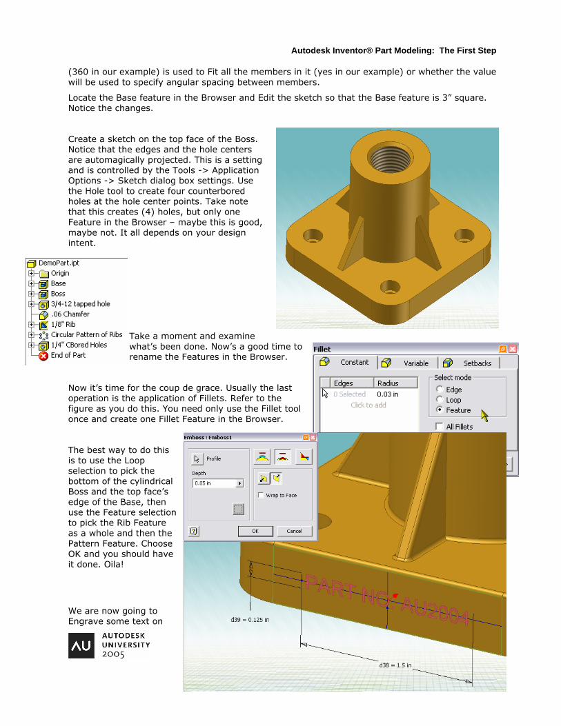
(360 in our example) is used to Fit all the members in it (yes in our example) or whether the value will be used to specify angular spacing between members.
Locate the Base feature in the Browser and Edit the sketch so that the Base feature is 3” square. Notice the changes.
Create a sketch on the top face of the Boss. Notice that the edges and the hole centers are automagically projected. This is a setting and is controlled by the Tools -> Application Options -> Sketch dialog box settings. Use the Hole tool to create four counterbored holes at the hole center points. Take note that this creates (4) holes, but only one Feature in the Browser – maybe this is good, maybe not. It all depends on your design intent.
Take a moment and examine what’s been done. Now’s a good time to rename the Features in the Browser.
Now it’s time for the coup de grace. Usually the last operation is the application of Fillets. Refer to the figure as you do this. You need only use the Fillet tool once and create one Fillet Feature in the Browser.
The best way to do this is to use the Loop selection to pick the bottom of the cylindrical Boss and the top face’s edge of the Base, then use the Feature selection to pick the Rib Feature as a whole and then the Pattern Feature. Choose OK and you should have it done. Oila!
We are now going to Engrave some text on
Autodesk Inventor® Part Modeling: The First Step

7
our part as if we were stamping a part number on it. On the left-front side of the Base feature left-click on the face. Press ‘S’ on the keyboard and you will be in Edit Sketch mode. Draw a construction line from the midpoint (green dot) of the left vertical line to the midpoint of the right vertical line. Draw another construction line from the midpoint of the top horizontal line to the midpoint of the bottom horizontal line. These will be used to center the Engraving text in the center of the face. Pick the Create Text tool from the 2D Sketch Panel and pick a point anywhere in the face. In the dialog box type in “PART NO. AU2004” and choose horizontal and vertical justification from the buttons along the top of the dialog box. Pick OK to exit the dialog box. You’ll notice a frame around the text. You’ll dimension to this frame to control the size of the text string. Use a value of 1.50 for the length and .125 for the text height. The location of the text string will be geometrically constrained by using Coincident constraints between the horizontal and vertical midpoints of the text frame and the horizontal and vertical construction lines created earlier. Select the Auto Dimension tool to ensure that you’ve eliminated all of the constraints needed. Pick Return to exit out of Edit Sketch mode. Select the Emboss tool from the Tool Panel. The same tool is used for Engraving (sunken letters) and Embossing (raised letters). The Profile will need to be specified carefully. You do not want to select the large face – only the text letters themselves. Refer to the Figure using a value of .05 for the depth of the letters and the other selections necessary – Engrave and direction.
The Emboss Feature should be in the Browser – right-click on it and choose Properties from the context menu. Change the Feature Color Style to Metal-Silver as shown in the Figure to the right.
Save your work because we’ll be using the model later on as we explore parametric control.
On Sweeps and Lofts
The Process for Creating a Sweep or Loft
The process is essentially the same for either creating a Sweep or a Loft Feature. That is why they are both covered in this Section.
Create paths or rails that are necessary to control the sketch’s direction or flow.
Create the work feature(s) that will hold the Sketch(es)
Create the Sketch(es) for the various cross sections
Use the Inventor tool – Sweep or Loft - to create the feature
Sweeps require two Sketches, usually at right angles to one another, but not necessarily. Lofts generally require more than two Sketches in order to achieve a smooth transition between Sections.
Autodesk Inventor® Part Modeling: The First Step

8
Creating 2D Sweep Features
Sweep Features are typically created for piping or tubing, but are not limited to these uses. You may be able to quickly create a feature with a Sweep that would take much longer with Extrude Cut & Join Features. For example, a picture frame with mitered corners is best modeled with a Sweep Feature. You’ll do that soon in Example-10-02. This Inventor tool has a variety of other applications in piping, tubing and other such types of geometry.
1.) Create a Sweep Path
The first step is to create a Path for the Sweep Feature. This is simply a Sketch on a Work Plane, dimensioned and constrained as any other. The path may be open or closed – depending on the shape of the final solid Feature. We’ll be doing just that in Example-10-03. For now, Open Example-10-01 and examine the two sketches setup there. If it’s piping, as in the Example, then the path will be open. If it’s the picture frame in Example-10-02 then the path is closed. Notice the path lies entirely on a plane and is therefore considered a 2D path. Later in this Chapter we’ll work with 3D paths and the ways of creating them. The default XZ Plane in Inventor was used for the path’s work plane, as was the XY Plane for the Sweep’s cross section. In our Example of the piping it is best to plan the path so that it originates at a known point, such as the origin 0,0. You’ll see why in a minute.
2.) Create a Cross Section
As stated above every Sweep Feature requires a Sketch that will serve as the cross-sectional profile of the Sweep feature. This sketch will, of course, either be on a part face or a Work Plane. In most cases, a Work Plane will be necessary. In Example-10-01 we have used the part’s XY Plane and the path starts at 0,0. With the cross section’s sketch on the part’s XY Plane then we are assured that the cross section is at the start of the path and that it intersects it. That is one of the stipulations in Inventor – that the cross section intersect the path in some way. Although it is not required that the cross-section begin at the path’s beginning – it may intersect the path somewhere along the path’s length. Go ahead and use the Inventor Sweep tool to sweep the cross section along the path in our Example. The Sweep tool is located on the Part Features Palette and is shown in Figure. The Profile and Path buttons are obvious, but the Output type bears some examination. Mainly, you will want to leave the setting where it is – to produce a solid, but take note that the other produces a surface. The More tab contains nothing more than an entry box for a Taper Angle value. Try it for the effect, but be careful as the taper angle runs out very quickly over the length of the sweep and soon results in an error. When finished take a moment to examine the results. Is it necessary that the cross section be perpendicular to the path? No, in fact, the cross section if angled to the path will result in a “foreshortened” cross sectional area, as in an ellipse from a circular sketch.
How to Constrain the Cross Section of a Sweep
Autodesk Inventor® Part Modeling: The First Step

9
The following Practice will show you how to create the Work Plane for the Cross Section of a Sweep and also how to constrain the Cross Section Sketch to the Path Sketch. Open Practice-10-01.ipt and examine the Path Sketch that is there already. The Path is all done. Your task is to create the Cross Section Sketch. The first step in that task is to put a Work Plane on the outer endpoint of the Path. Pick the Work Plane tool and pick the endpoint of the Path – the endpoint, not the line. Once that’s done then pick the line.
This is an effective method of placing a Work Plane perpendicular to a line in a Sketch. With the Work Plane in place it’s a simple matter of creating a Sketch on it – do so.
The default coordinate system of the Sketch will have the Z axis pointing into the Sketch – towards the upper left hand corner of the screen. We don’t want that – Return back to the Part environment, right click on the Work Plane in the Browser, choose Flip Normal, and double-click on the new Sketch and you should find the Z axis pointing out as shown in Figure XX. Our Cross Section Sketch will be a circle, of course. In order for the Sketch to be constrained to the Path we must Project the endpoint of the Path onto our Cross Section Sketch. Do so now. You should notice a slightly darker dot at the end of the Path. Turn off the coordinate system indicator, if necessary. Now, pick the Circle tool and hover over the Projected endpoint. There should appear a green dot. If not, then you hadn’t Projected the endpoint successfully. If there is a green dot pick the endpoint of the Path and drag the circle’s radius out a small way. Dimension the circle’s diameter (.05) and it should be fully constrained. It is very important to Project the Path’s endpoint first, then draw the Cross Section’s geometry. If you don’t then you’ll find it very difficult to constrain the new geometry to that Projected endpoint’s dot. Return to the Part environment and pick the Sweep tool from the Tool Panel and complete the Part.
Creating 3D Sweeps
Although 2D Sweeps are great Inventor is a 3D modeling software application and the need for 3D Sweeps is everywhere in engineering today. The applications include wiring, piping, tubing, etc. 3D Sweeps can be created in Part files (ipt) or Assembly files (iam). 3D Sweeps are based on a 3D Sketch which is basically the Path for the 3D Sweep. 3D Sketches are created with lines and work features, such as Work Points and Work Planes. Creating a 3D Sketch is the hard part. Once that’s done the Sweep tool takes care of the rest. The basic principle to creating a 3D Sketch is define Work Points and then connect the dots with a line.
In the next two Examples we are going to create the same 3D Sweep for a pipe run, but we’re going to use two different methods. The first Example-10-04 is easier than the second Example-10-05. Both are very good examples of 3D Sweeps in Inventor. Open Example-10-04 and examine
Autodesk Inventor® Part Modeling: The First Step
10
what is setup for you. Notice the Work Planes in the Browser – they are named according to the offset values used to create them. The finished version of the Example is shown in Figure.
As you can see the Work Planes that are setup in Example-10-04 will be instrumental in creating
our 3D Sweep. Right-click on the model background and choose New 3D Sketch. Notice that a 3D Sketch icon appears in the Browser. You will be creating seven (7) Work Points in the following steps. When finished you will then connect the Work Points with a Line using the Auto-Bend feature to include fillet radii at the corners. Let’s begin:
TIP: Keep in mind that if you can’t pick a particular Work Plane in the model screen then you can easily select it in the Browser.
Select the Work Point tool from the 3D Sketch Palette. It takes three (3) planes to define a point –right? So pick three Work Planes to define the first Work Point (in any order): The XZ Plane, the YZ Plane and then the Work Plane Start. A Work Point should appear on the model screen at the intersection of the three Work Planes.
The Work Point tool is repeating so no need to select it from the Palette. Pick the XZ Plane, the YZ Plane and the Work Plane 6in. Another Work Point should appear.
Continue on for the third point. Pick the YZ Plane, the Work Plane 6in and the Work Plane 42in. Getting the idea?
Pick the Work Plane 6in, the Work Plane 36in and the Work Plane 42in. Got a Work Point? Don’t get cocky now.
Pick the Work Plane 36in, the Work Plane 42in and the Work Plane 54in. Almost there.
Pick the XZ Plane, the Work Plane 35in and the Work Plane 54in. One more to go.
Pick the XZ Plane, the Work Plane 30in and the Work Plane 54in. All done! Very good!
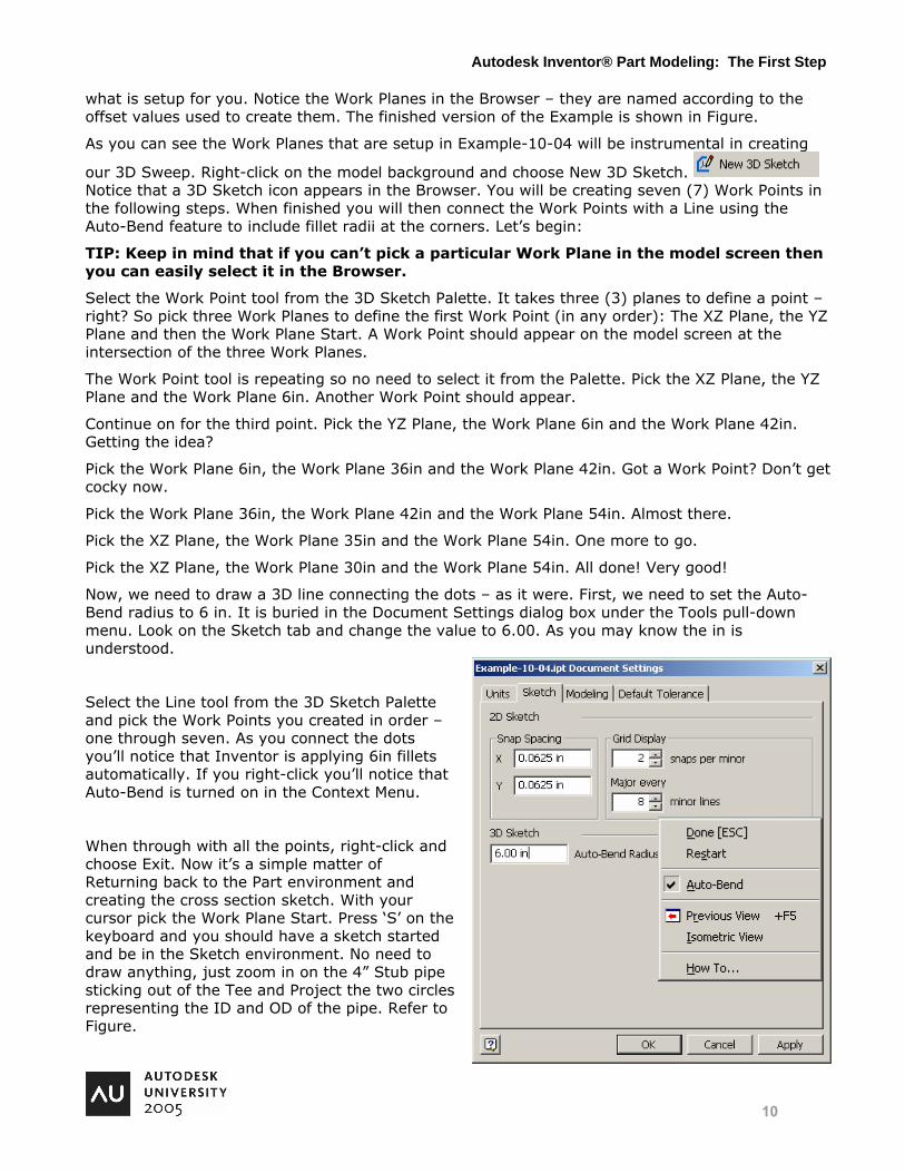
Now, we need to draw a 3D line connecting the dots – as it were. First, we need to set the Auto-Bend radius to 6 in. It is buried in the Document Settings dialog box under the Tools pull-down menu. Look on the Sketch tab and change the value to 6.00. As you may know the in is understood.
Select the Line tool from the 3D Sketch Palette and pick the Work Points you created in order – one through seven. As you connect the dots you’ll notice that Inventor is applying 6in fillets automatically. If you right-click you’ll notice that Auto-Bend is turned on in the Context Menu.
When through with all the points, right-click and choose Exit. Now it’s a simple matter of Returning back to the Part environment and creating the cross section sketch. With your cursor pick the Work Plane Start. Press ‘S’ on the keyboard and you should have a sketch started and be in the Sketch environment. No need to draw anything, just zoom in on the 4” Stub pipe sticking out of the Tee and Project the two circles representing the ID and OD of the pipe. Refer to Figure.
Autodesk Inventor® Part Modeling: The First Step
11
No need to constrain anything either. Finish the sketch and select the Sweep tool from the Palette. Pick the sketch for the Profile and the 3D line path that you created for the Path. Choose OK and step back and admire your work. Pay close attention to the anatomy of the 3D Sweep in the Browser.
Editing the 3D Sweep
How do you edit the 3D Sweep? Mainly, this involves editing the 3D Sketch that controls the 3D Sweep. And editing that will depend on how it was made. In Example-10-04 you would change the offset values on the Work Planes that control the Work Points of the 3D Sketch. In Example-10-05 you would do the same except the Work Planes are “buried” in the 3D Sketch and you would have to uncover them to change the offset values. Keep in mind that these offset values could be equations or User Parameters.
Creating Loft Features
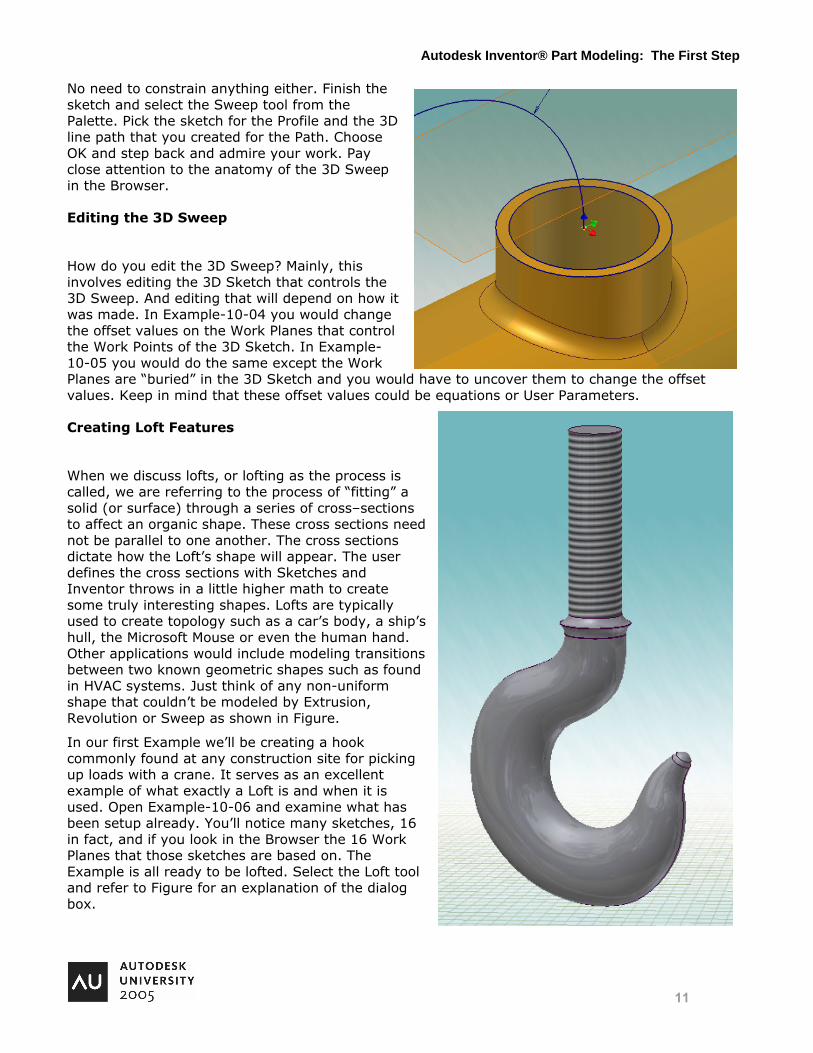
When we discuss lofts, or lofting as the process is called, we are referring to the process of “fitting” a solid (or surface) through a series of cross–sections to affect an organic shape. These cross sections need not be parallel to one another. The cross sections dictate how the Loft’s shape will appear. The user defines the cross sections with Sketches and Inventor throws in a little higher math to create some truly interesting shapes. Lofts are typically used to create topology such as a car’s body, a ship’s hull, the Microsoft Mouse or even the human hand. Other applications would include modeling transitions between two known geometric shapes such as found in HVAC systems. Just think of any non-uniform shape that couldn’t be modeled by Extrusion, Revolution or Sweep as shown in Figure.
In our first Example we’ll be creating a hook commonly found at any construction site for picking up loads with a crane. It serves as an excellent example of what exactly a Loft is and when it is used. Open Example-10-06 and examine what has been setup already. You’ll notice many sketches, 16 in fact, and if you look in the Browser the 16 Work Planes that those sketches are based on. The Example is all ready to be lofted. Select the Loft tool and refer to Figure for an explanation of the dialog box.
Autodesk Inventor® Part Modeling: The First Step
Edit Document Properties for Course Name
12
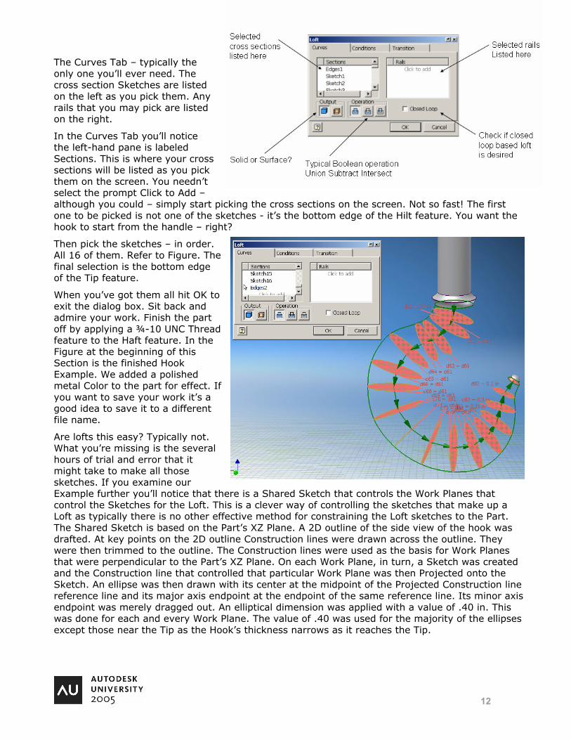
The Curves Tab – typically the only one you’ll ever need. The cross section Sketches are listed on the left as you pick them. Any rails that you may pick are listed on the right.
In the Curves Tab you’ll notice the left-hand pane is labeled Sections. This is where your cross sections will be listed as you pick them on the screen. You needn’t select the prompt Click to Add – although you could – simply start picking the cross sections on the screen. Not so fast! The first one to be picked is not one of the sketches - it’s the bottom edge of the Hilt feature. You want the hook to start from the handle – right?
Then pick the sketches – in order. All 16 of them. Refer to Figure. The final selection is the bottom edge of the Tip feature.
When you’ve got them all hit OK to exit the dialog box. Sit back and admire your work. Finish the part off by applying a ¾-10 UNC Thread feature to the Haft feature. In the Figure at the beginning of this Section is the finished Hook Example. We added a polished metal Color to the part for effect. If you want to save your work it’s a good idea to save it to a different file name.
Are lofts this easy? Typically not. What you’re missing is the several hours of trial and error that it might take to make all those sketches. If you examine our Example further you’ll notice that there is a Shared Sketch that controls the Work Planes that control the Sketches for the Loft. This is a clever way of controlling the sketches that make up a Loft as typically there is no other effective method for constraining the Loft sketches to the Part. The Shared Sketch is based on the Part’s XZ Plane. A 2D outline of the side view of the hook was drafted. At key points on the 2D outline Construction lines were drawn across the outline. They were then trimmed to the outline. The Construction lines were used as the basis for Work Planes that were perpendicular to the Part’s XZ Plane. On each Work Plane, in turn, a Sketch was created and the Construction line that controlled that particular Work Plane was then Projected onto the Sketch. An ellipse was then drawn with its center at the midpoint of the Projected Construction line reference line and its major axis endpoint at the endpoint of the same reference line. Its minor axis endpoint was merely dragged out. An elliptical dimension was applied with a value of .40 in. This was done for each and every Work Plane. The value of .40 was used for the majority of the ellipses except those near the Tip as the Hook’s thickness narrows as it reaches the Tip.
13
Why are so many sketches necessary? Seems like a lot of work. If you want the final loft shape to be smooth and conform to specifications you’ll create as many sketches as it takes. As an experiment, open Example-10-06 again and this time select only a few of the sketches – skipping over intermediate ones and see what the final Loft shape is. Chances are you’ll get an error because Inventor doesn’t have enough information to make a smooth transition from one sketch to another – the changes in direction are too abrupt.
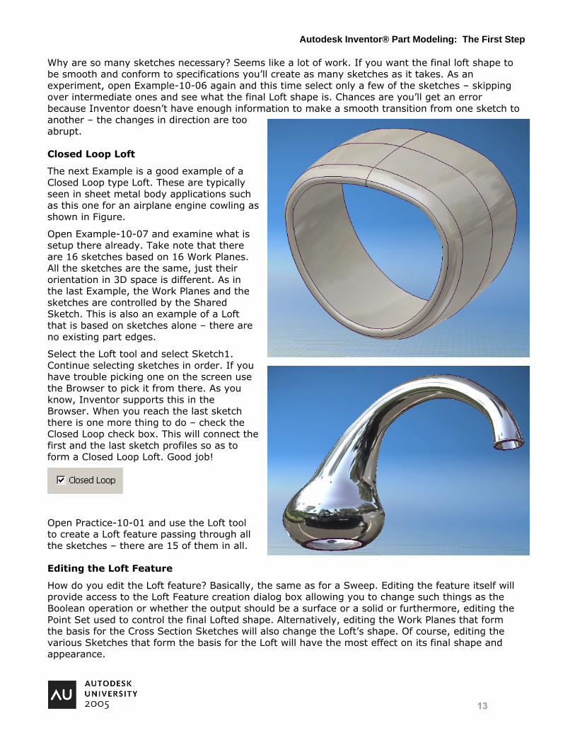
Closed Loop Loft
The next Example is a good example of a Closed Loop type Loft. These are typically seen in sheet metal body applications such as this one for an airplane engine cowling as shown in Figure.
Open Example-10-07 and examine what is setup there already. Take note that there are 16 sketches based on 16 Work Planes. All the sketches are the same, just their orientation in 3D space is different. As in the last Example, the Work Planes and the sketches are controlled by the Shared Sketch. This is also an example of a Loft that is based on sketches alone – there are no existing part edges.
Select the Loft tool and select Sketch1. Continue selecting sketches in order. If you have trouble picking one on the screen use the Browser to pick it from there. As you know, Inventor supports this in the Browser. When you reach the last sketch there is one more thing to do – check the Closed Loop check box. This will connect the first and the last sketch profiles so as to form a Closed Loop Loft. Good job!
Open Practice-10-01 and use the Loft tool to create a Loft feature passing through all the sketches – there are 15 of them in all.
Editing the Loft Feature
How do you edit the Loft feature? Basically, the same as for a Sweep. Editing the feature itself will provide access to the Loft Feature creation dialog box allowing you to change such things as the Boolean operation or whether the output should be a surface or a solid or furthermore, editing the Point Set used to control the final Lofted shape. Alternatively, editing the Work Planes that form the basis for the Cross Section Sketches will also change the Loft’s shape. Of course, editing the various Sketches that form the basis for the Loft will have the most effect on its final shape and appearance.
Autodesk Inventor® Part Modeling: The First Step

14
On Parametric Design
In Inventor there are several methods available to affect parametric control. They are discussed below in order of parametric control they provide to the designer:
1st - Numeric Values
From the very basic in which you dimension a sketch with numeric values – specifically telling Inventor what a given distance will be always. Example – 5.00”. You have seen these in use everyday. Why are they so limiting?
2nd - Equations
Next in line would be wherein you specify relationships between those dimension values. Example: D1=D0/2. In this method the dimension D1 has no explicit numeric value, instead it is “driven” in relation to the value of D0. You have seen this method employed here today. It has its advantages.
3rd - Model Parameters
Moving along we have the concept of Model Parameters. Inventor provides a special dialog box for our use as we can rename the D0, D1 dimension labels and give them sensible English names that help to identify their use. Mathematical equations may be set up as in the previous method.
4th - Microsoft Excel Spreadsheet
Further along we learn that we can take those Named Parameters and list them in a spreadsheet and further manipulate them therein using the inherent power of Excel’s logic functions to arrive at values for our designs.
Autodesk Inventor® Part Modeling: The First Step
15
5th - iParts
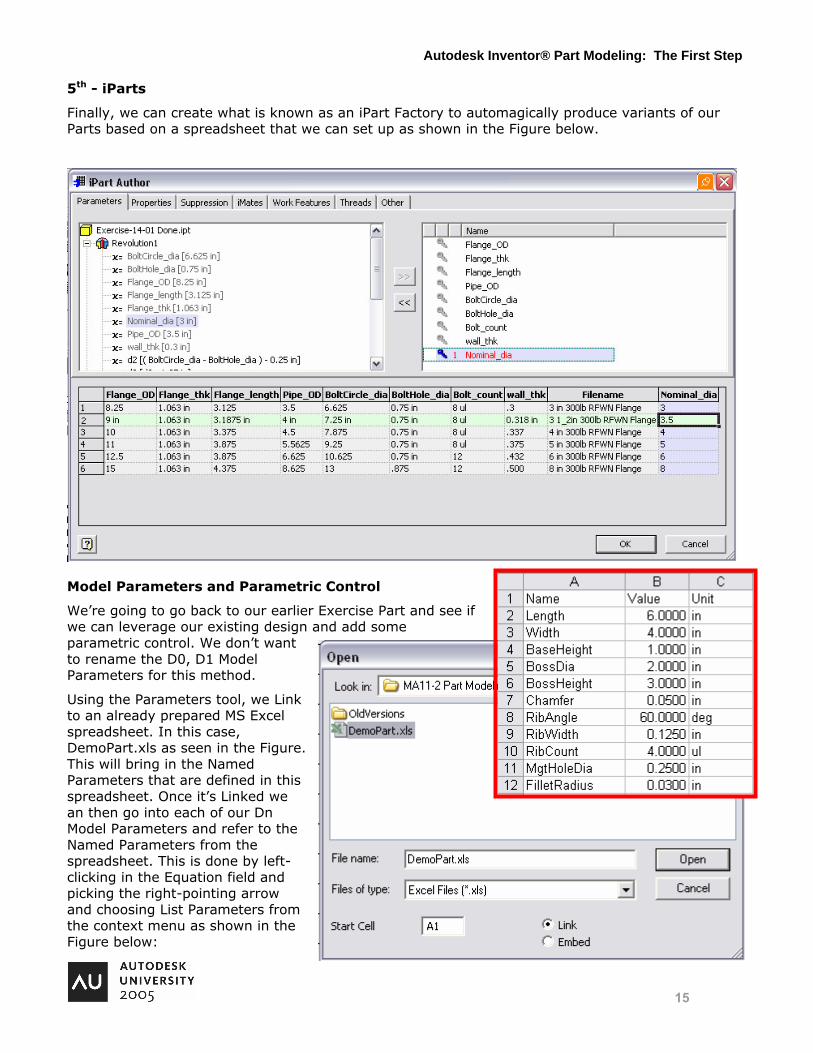
Finally, we can create what is known as an iPart Factory to automagically produce variants of our Parts based on a spreadsheet that we can set up as shown in the Figure below.
Model Parameters and Parametric Control
We’re going to go back to our earlier Exercise Part and see if we can leverage our existing design and add some parametric control. We don’t want to rename the D0, D1 Model Parameters for this method.
Using the Parameters tool, we Link to an already prepared MS Excel spreadsheet. In this case, DemoPart.xls as seen in the Figure. This will bring in the Named Parameters that are defined in this spreadsheet. Once it’s Linked we an then go into each of our Dn Model Parameters and refer to the Named Parameters from the spreadsheet. This is done by left-clicking in the Equation field and picking the right-pointing arrow and choosing List Parameters from the context menu as shown in the Figure below:
Autodesk Inventor® Part Modeling: The First Step

16
The Parameter names are left alone while in the Equation area the Linked Parameters are used to
control those Features in the Part. From then on the Part is manipulated via the spreadsheet. Furthermore, there is an entry in the Browser for the 3rd Party linked spreadsheet.
IParts
Time permitting, we will demonstrate making an iPart out of this Demo Exercise. It is a bit involved and out of the scope of this class, but basically once you understand the principles outlined above you can do it. It requires that the Dn Parameter Names be renamed to meaningful English words, such as Length and Width. Once done, from the Tools pulldown menu choose create iPart and you’ll be presented with a dialog box giving you full control over all of the Named Parameters you defined.
In Closing
I hope that everyone agrees that effective Part Modeling is something that can be learned and applied to make your part designs smarter and more efficient. It has been shown that Autodesk Inventor is packed with the tools and features that are required to produce today’s complex parts in today’s complex world. I hope that you now have the knowledge you need to go back to the office and design it better, faster and cheaper.
I sincerely thank you for your time and attention,
Anthony Dudek
Thomas Short, P.E.
Portions reprinted from “Learning Inventor 10” published by Goodheart-Willcox publishers.
Autodesk Inventor® Part Modeling: The First Step