Autodesk User Group International AUGI Training Program (ATP) · Autodesk User Group International...
15
Autodesk User Group International AUGI Training Program (ATP) This course (and every course you are registered for) will only continue if you re-register for it after completing every segment. To do this (and you can re-register for all the courses you're taking at one time for each segment) use the ATP website Registration page. It will be updated with each segment (A, B, C, D and E) and you will need to re-register using it to keep the courses you signed up for going this semester. No one is forcing you to do this, but if you don't, your courses may get cancelled. It's that simple. If you have a question or comment about the content of any segment, we encourage you to post a message to your course’s corresponding ATP Mail Lists. Teachers moderate their class mail list and may take up to two days to respond to questions you put to them. Proper use of any ATP Mail List is outlined on the ATP Mail List web page. If you have a question or comment about the ATP program in general, you can write to [email protected] . Please do not write to [email protected] with questions about course content unless there is a typo or a technical problem with a file. You are welcome to publish the content of this or any ATP course segment for the benefit of your Local User Group or co-workers so long as AUGI and the course instructor receive full credit for generating it. The content of this course may not be sold in any form and is copyrighted. This lesson and other AUGI Training Program materials have been generated by the faculty and staff of Autodesk User Group International, a non-profit user- focused organization which depends on your participation. Autodesk, the Autodesk logo, AutoCAD, 3D Studio MAX, 3D Studio VIZ, AutoCAD LT, Visual LISP, and AutoLISP are registered trademarks of Autodesk, Inc., in the USA and/or other countries. AUGI is a servicemark of Autodesk, Inc., licensed exclusively to the Autodesk User Group International. Windows95, Windows98, Windows NT and Windows 2000, Visual Basic, Microsoft Word, Microsoft Excel, and Microsoft Access are trademarks of Microsoft Corporation. All other brand names, product names, or trademarks belong to their respective holders. Copyright 2001 AUGI. All rights reserved. -The ATP Staff
-
Upload
nguyendang -
Category
Documents
-
view
227 -
download
0
Transcript of Autodesk User Group International AUGI Training Program (ATP) · Autodesk User Group International...
Autodesk User Group International AUGI Training Program (ATP)
This course (and every course you are registered for) will only continue if you re-register for it after completing every segment. To do this (and you can re-register for all the courses you're taking at one time for each segment) use the ATP website Registration page. It will be updated with each segment (A, B, C, D and E) and you will need to re-register using it to keep the courses you signed up for going this semester. No one is forcing you to do this, but if you don't, your courses may get cancelled. It's that simple. If you have a question or comment about the content of any segment, we encourage you to post a message to your course’s corresponding ATP Mail Lists. Teachers moderate their class mail list and may take up to two days to respond to questions you put to them. Proper use of any ATP Mail List is outlined on the ATP Mail List web page. If you have a question or comment about the ATP program in general, you can write to [email protected]. Please do not write to [email protected] with questions about course content unless there is a typo or a technical problem with a file. You are welcome to publish the content of this or any ATP course segment for the benefit of your Local User Group or co-workers so long as AUGI and the course instructor receive full credit for generating it. The content of this course may not be sold in any form and is copyrighted. This lesson and other AUGI Training Program materials have been generated by the faculty and staff of Autodesk User Group International, a non-profit user-focused organization which depends on your participation. Autodesk, the Autodesk logo, AutoCAD, 3D Studio MAX, 3D Studio VIZ, AutoCAD LT, Visual LISP, and AutoLISP are registered trademarks of Autodesk, Inc., in the USA and/or other countries. AUGI is a servicemark of Autodesk, Inc., licensed exclusively to the Autodesk User Group International. Windows95, Windows98, Windows NT and Windows 2000, Visual Basic, Microsoft Word, Microsoft Excel, and Microsoft Access are trademarks of Microsoft Corporation. All other brand names, product names, or trademarks belong to their respective holders. Copyright 2001 AUGI. All rights reserved. -The ATP Staff
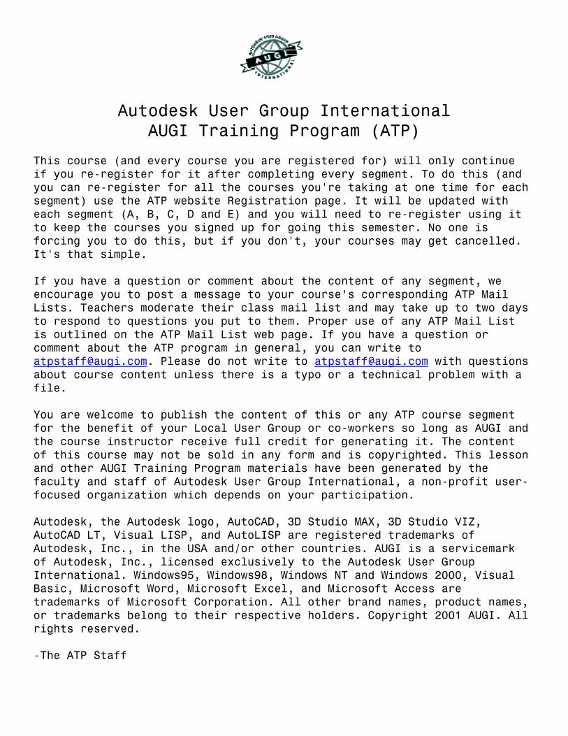
ATP007B – “Creating 3D Objects” Faculty: Diev Hart (2.1) Intro/Review – In this section we will cover the basics on how to create 3D objects using different methods like extruding and revolving closed 2D regions and using boolean operations to create more complex objects, along with simple 3D Polylines and Meshes and Surfaces. When doing design in 3D you will want to stay as organized as possible so lets get in the habit of putting objects on different layers and using different colors. Once you have a lot of 3D objects on your screen it will be easier to distinguish between them, and freeze or turn off (objects) layers. (fig06)
layer_color.jpg (fig06)
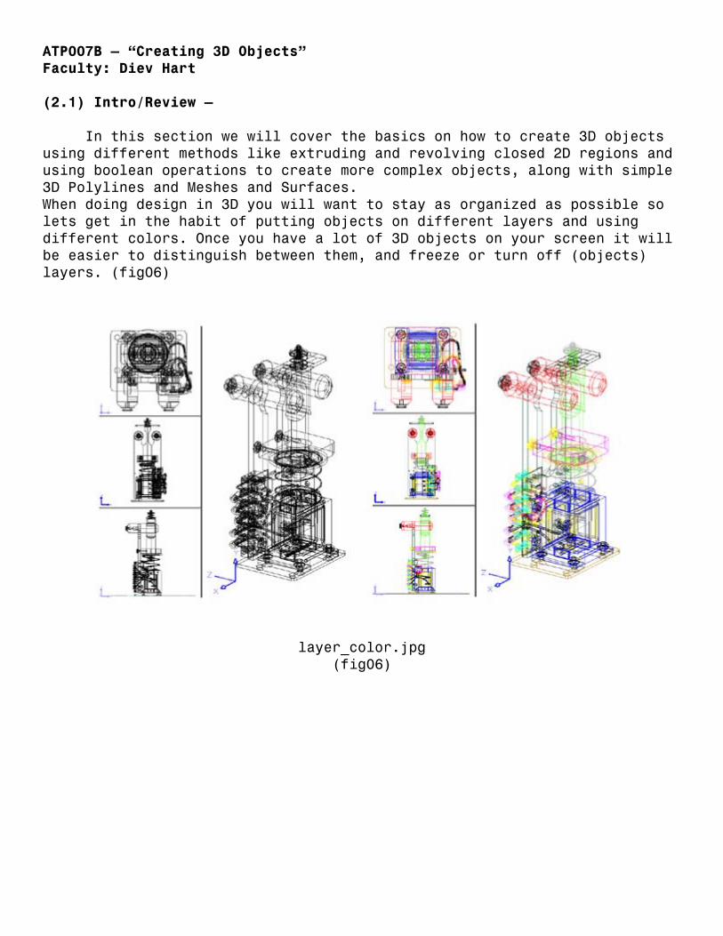
(2.1) Intro/Review - (continued) You will also want to become familiar with the 3DORBIT command. Using this powerful command we will easily be able to change how we are viewing our objects, either using parallel or perspective viewing, our distance to our objects, the shade modes of our objects, our zoom factor and our clipping planes to name a few. I will not be covering this command in anymore detail until later on so it’s up to you to use it now if you like. You may want to come back to this section later after you have a few objects on your screen so you can really play and see the effects. All I can say is play with this until you understand the movement, after you are in the command you will hold down your pick button on your mouse and drag to change the view. (Right click to get to the menu) (fig07)
3dorbit.jpg (fig07)
(2.2) Basic 3D objects – The first thing I am going to say is SAVE YOUR WORK EVERY 20 MINUTES!!!! (I’ll say it again so you remember save your work every 20 minutes) If you get in the habit now it will save lots of hair in the future. Another note; I’m doing everything at the command line for simplicity but you could use toolbars and pull downs if you like.
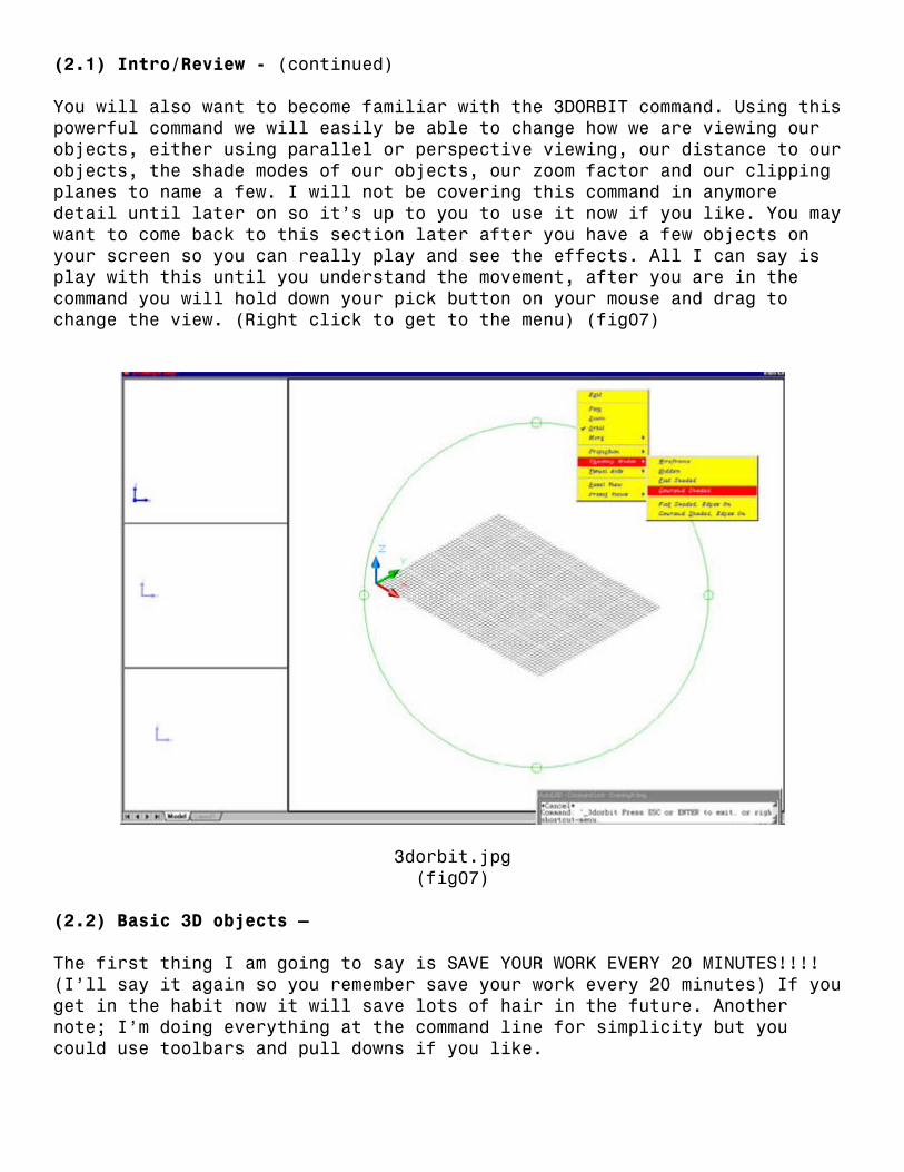
(2.2) Basic 3D Objects – (continued) There are three types of 3D objects; 3D wireframes, meshes, and solids. Remember you can have 2D objects with thickness but I don’t call them 3D objects. We will be using solids most of the time but lets start by adding a 3D wireframe a mesh. If we continue where we left off you should have your top, front, right and SE Iso viewports, if not set your screen up like this by reviewing A segment. We will start by adding a 3D Polyline, click your top viewport to make it current, then type “3DPOLY” (enter) on the command line, now type “0,0,0” (enter) to start the 3D Polyline at our origin. Our next point will be “4,0,0” (enter), than “4,4,4” (enter), then type in “0,4,4” (enter) followed by “0,0,4” (enter) and “C” (enter) to close. This may look like a box in some viewports but if we click in the SE Isometric viewport and type “3DORBIT” (enter) (and click/drag) we will see the true shape of this 3D Polyline. (fig08)
3dpoly.jpg (fig08)

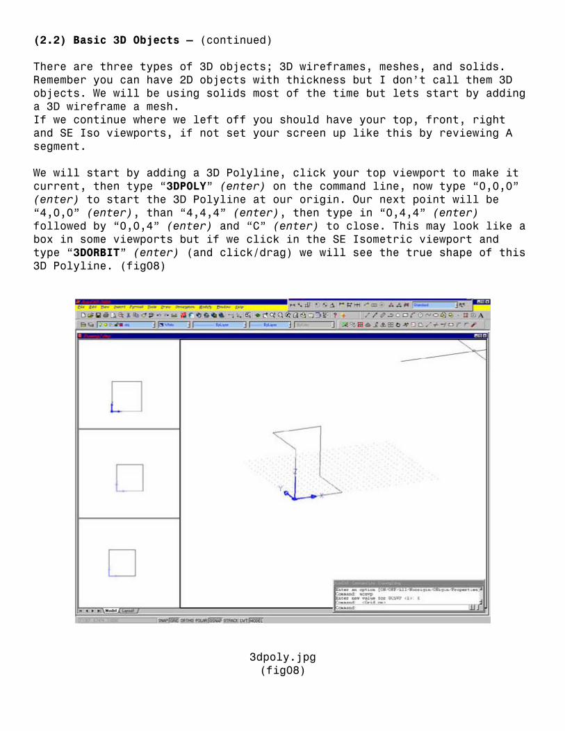
(2.2) Basic 3D Objects – (continued) Play around with this and add another with your own points and when your happy with it save your work, (3dpoly.dwg) so you can come back and review it later. Now lets start a new drawing and create a 3D MESH. There are other types but we really want solids so I’m just covering this one to give you an understanding of them. Type “3DMESH” (enter) at the command line, then “5”(enter) for the size in the M direction, then “4” (enter) for the size in the N direction. We will type in the coordinates, but you could just pick them in a viewport, starting at the lower left and working your way up 4 points (N direction), than moving to the right (M direction) and going up 4 more and over again etc. until you have your mesh. The only problem is that this is a 2D Mesh (fig09a) because you can’t give a Z value with a mouse pick.
2dmesh.jpg (fig09a)
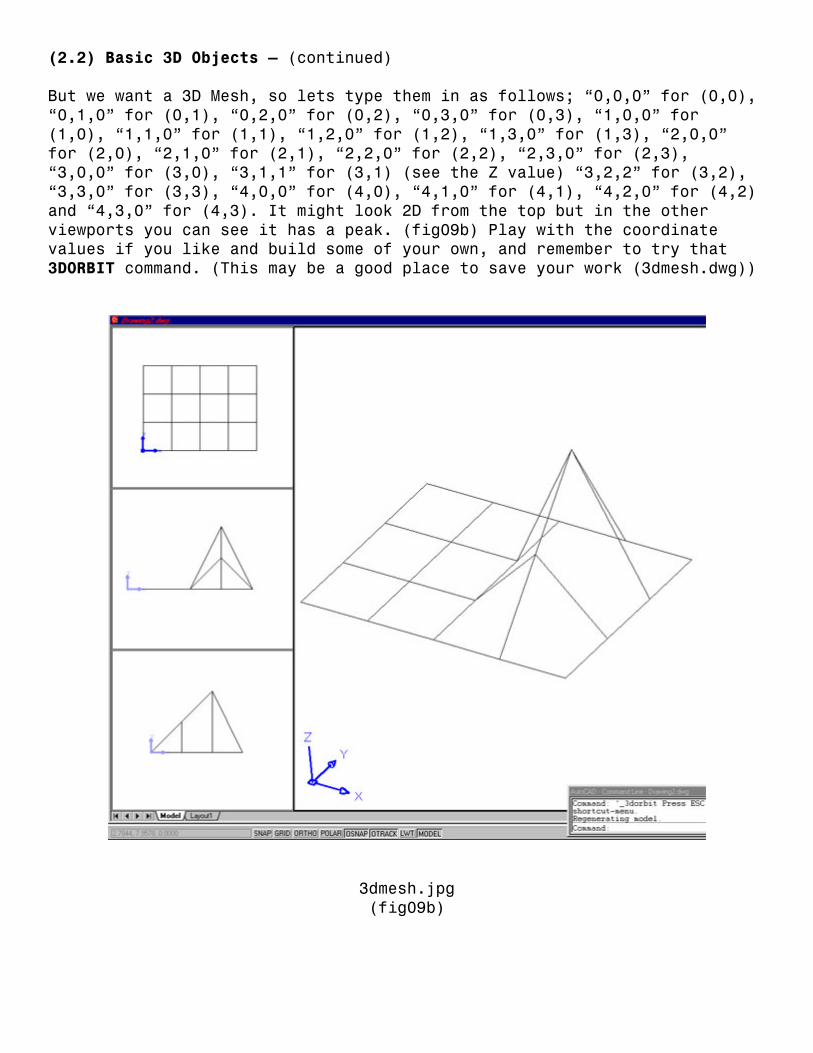
(2.2) Basic 3D Objects – (continued) But we want a 3D Mesh, so lets type them in as follows; “0,0,0” for (0,0), “0,1,0” for (0,1), “0,2,0” for (0,2), “0,3,0” for (0,3), “1,0,0” for (1,0), “1,1,0” for (1,1), “1,2,0” for (1,2), “1,3,0” for (1,3), “2,0,0” for (2,0), “2,1,0” for (2,1), “2,2,0” for (2,2), “2,3,0” for (2,3), “3,0,0” for (3,0), “3,1,1” for (3,1) (see the Z value) “3,2,2” for (3,2), “3,3,0” for (3,3), “4,0,0” for (4,0), “4,1,0” for (4,1), “4,2,0” for (4,2) and “4,3,0” for (4,3). It might look 2D from the top but in the other viewports you can see it has a peak. (fig09b) Play with the coordinate values if you like and build some of your own, and remember to try that 3DORBIT command. (This may be a good place to save your work (3dmesh.dwg))
3dmesh.jpg (fig09b)
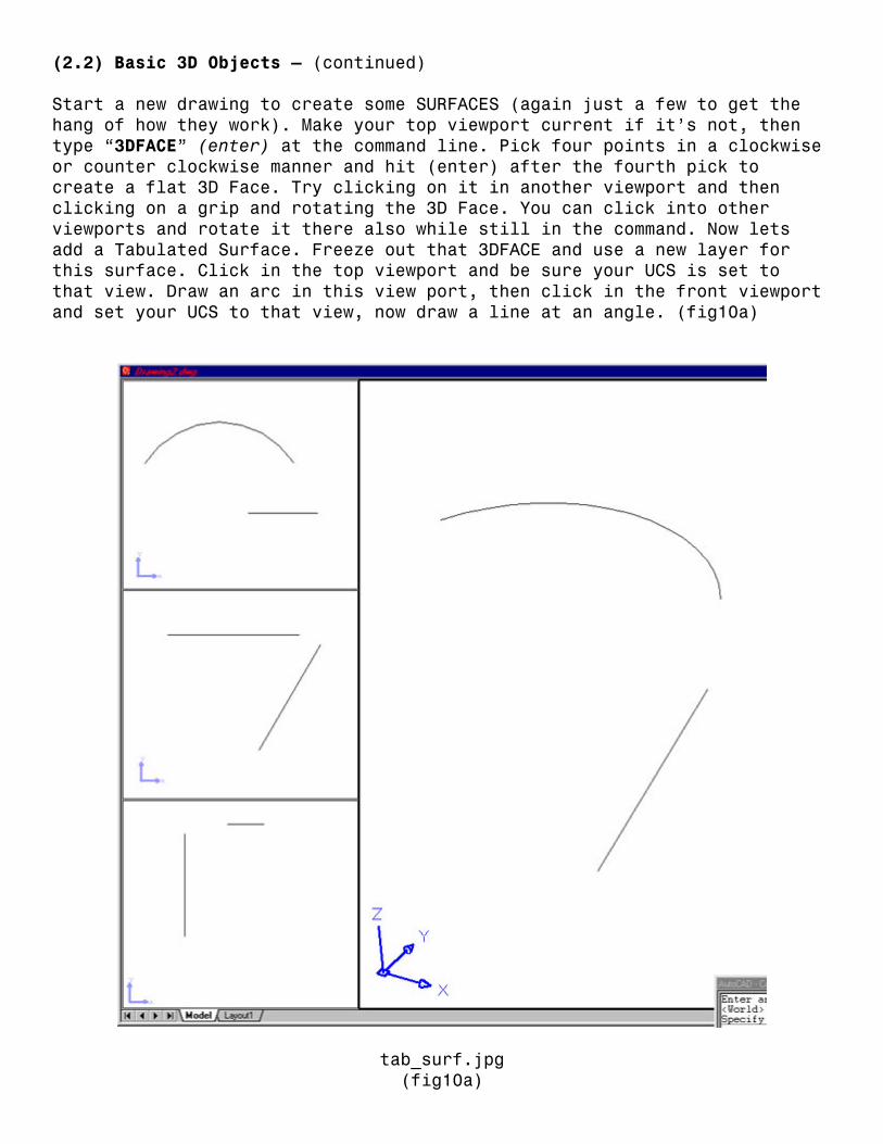
(2.2) Basic 3D Objects – (continued) Start a new drawing to create some SURFACES (again just a few to get the hang of how they work). Make your top viewport current if it’s not, then type “3DFACE” (enter) at the command line. Pick four points in a clockwise or counter clockwise manner and hit (enter) after the fourth pick to create a flat 3D Face. Try clicking on it in another viewport and then clicking on a grip and rotating the 3D Face. You can click into other viewports and rotate it there also while still in the command. Now lets add a Tabulated Surface. Freeze out that 3DFACE and use a new layer for this surface. Click in the top viewport and be sure your UCS is set to that view. Draw an arc in this view port, then click in the front viewport and set your UCS to that view, now draw a line at an angle. (fig10a)
tab_surf.jpg (fig10a)

(2.2) Basic 3D Objects – (continued) Now type “TABSURF” (enter) and for the path curve pick the arc, for the direction vector we will pick the line (while still in the front viewport) Notice the side or end of the line you pick determines the direction. Next lets add a Ruled Surface. Just UNDO back to the arc and line then type “RULESURF” (enter) (remember you can adjust the SURFTAB variables to make the Surfaces more or less dense) now pick the arc and the line for the defining curves. That’s it, very simple surface between to objects, so play around and add a few different shapes/objects and put a Ruled Surface between them. For the last one lets add an Edge Surface. Make a new layer and set it current (freeze out the others) and click in the top viewport to make it current. Lets create a simple ship hull. Set your UCS to that view and draw an arc, now click in your front viewport to make it current and set your UCS to that view, draw another arc. Click in the right viewport, set your UCS and draw the last arc. (fig10b) Now we want to connect all the endpoints. (move or use the grips) (might have to change the UCS)(fig10c).
edge_surf1.jpg (fig10b)

(2.2) Basic 3D Objects – (continued)
edge_surf2.jpg (fig10c)
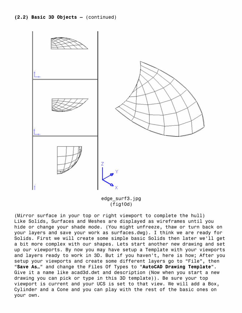
Now in order to create an Edge Surface we need 4 sides and we only have three so we are going to break one arc into two. This way we will have 4 objects but it will still look the same (just break an arc using the F option and use its midpoint for both points). We are ready, so type “EDGESURF” (enter) and pick your 4 objects to create the surface. (fig10d) (If you get an error, zoom in and look at your endpoints, they might not really meet).
(2.2) Basic 3D Objects – (continued)
edge_surf3.jpg (fig10d)
(Mirror surface in your top or right viewport to complete the hull) Like Solids, Surfaces and Meshes are displayed as wireframes until you hide or change your shade mode. (You might unfreeze, thaw or turn back on your layers and save your work as surfaces.dwg). I think we are ready for Solids. First we will create some simple basic Solids then later we’ll get a bit more complex with our shapes. Lets start another new drawing and set up our viewports. By now you may have setup a Template with your viewports and layers ready to work in 3D. But if you haven’t, here is how; After you setup your viewports and create some different layers go to “File”, then “Save As…” and change the Files Of Types to “AutoCAD Drawing Template”. Give it a name like acad3d.dwt and description (Now when you start a new drawing you can pick or type in this 3D template)). Be sure your top viewport is current and your UCS is set to that view. We will add a Box, Cylinder and a Cone and you can play with the rest of the basic ones on your own.
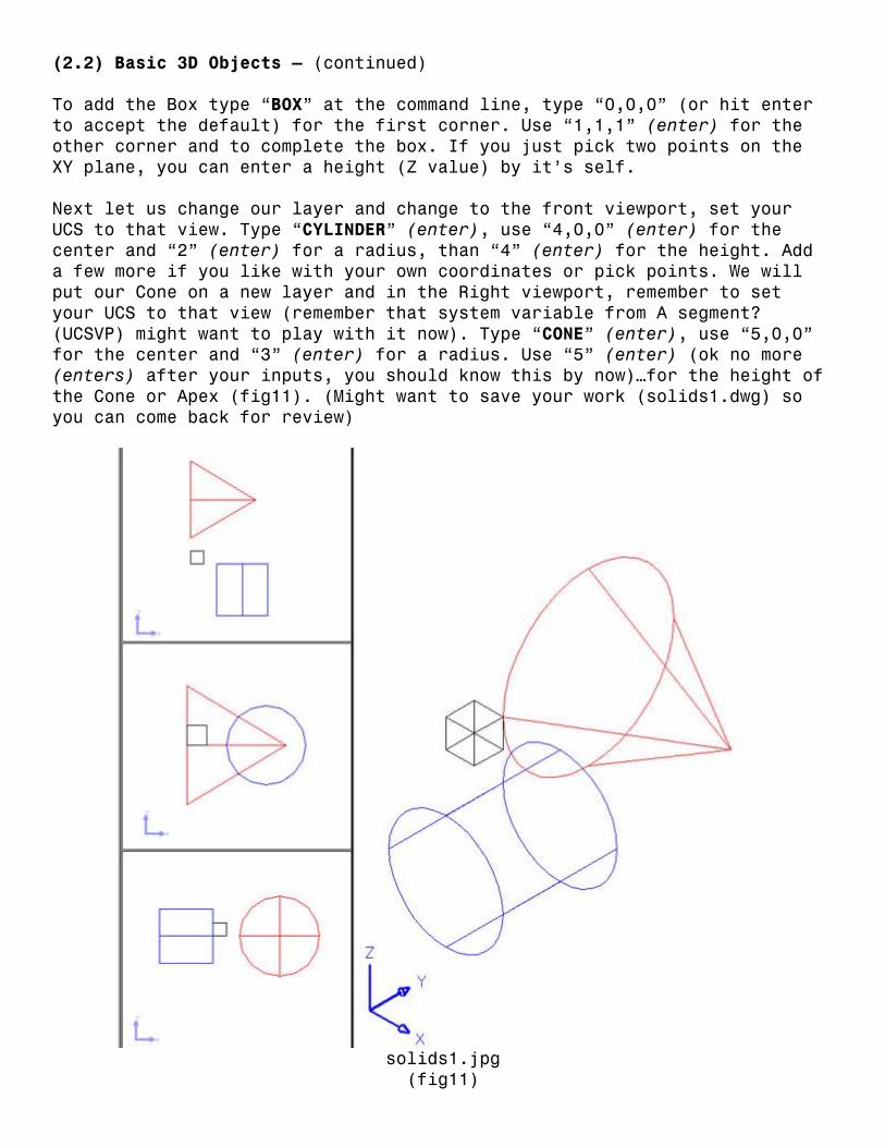
(2.2) Basic 3D Objects – (continued) To add the Box type “BOX” at the command line, type “0,0,0” (or hit enter to accept the default) for the first corner. Use “1,1,1” (enter) for the other corner and to complete the box. If you just pick two points on the XY plane, you can enter a height (Z value) by it’s self. Next let us change our layer and change to the front viewport, set your UCS to that view. Type “CYLINDER” (enter), use “4,0,0” (enter) for the center and “2” (enter) for a radius, than “4” (enter) for the height. Add a few more if you like with your own coordinates or pick points. We will put our Cone on a new layer and in the Right viewport, remember to set your UCS to that view (remember that system variable from A segment? (UCSVP) might want to play with it now). Type “CONE” (enter), use “5,0,0” for the center and “3” (enter) for a radius. Use “5” (enter) (ok no more (enters) after your inputs, you should know this by now)…for the height of the Cone or Apex (fig11). (Might want to save your work (solids1.dwg) so you can come back for review)
solids1.jpg (fig11)
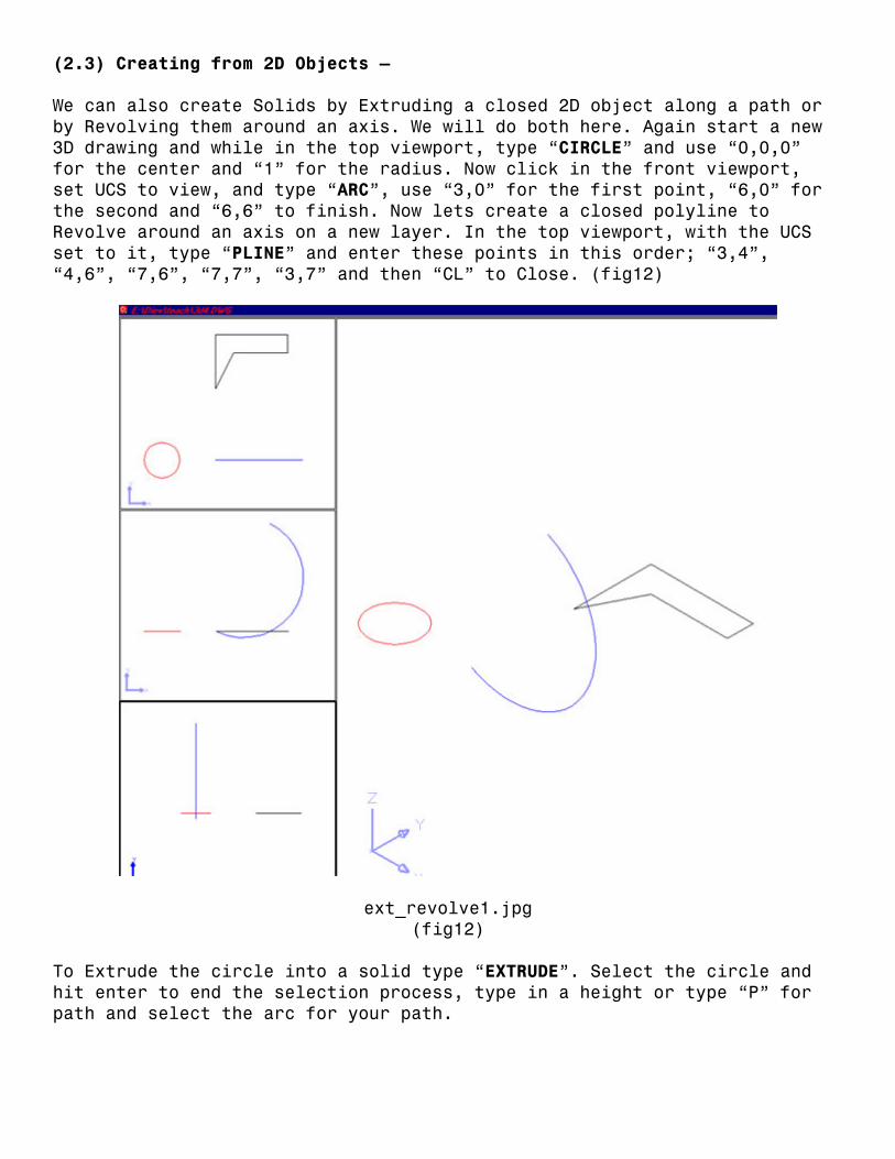
(2.3) Creating from 2D Objects – We can also create Solids by Extruding a closed 2D object along a path or by Revolving them around an axis. We will do both here. Again start a new 3D drawing and while in the top viewport, type “CIRCLE” and use “0,0,0” for the center and “1” for the radius. Now click in the front viewport, set UCS to view, and type “ARC”, use “3,0” for the first point, “6,0” for the second and “6,6” to finish. Now lets create a closed polyline to Revolve around an axis on a new layer. In the top viewport, with the UCS set to it, type “PLINE” and enter these points in this order; “3,4”, “4,6”, “7,6”, “7,7”, “3,7” and then “CL” to Close. (fig12)
ext_revolve1.jpg (fig12)
To Extrude the circle into a solid type “EXTRUDE”. Select the circle and hit enter to end the selection process, type in a height or type “P” for path and select the arc for your path.

(2.3) Creating from 2D Objects – (continued) Type “REVOLVE” and pick the polyline (enter to end the selection), you create an axis by picking two points or by selecting and axis and selecting a point on it. Lets pick two points on the very top horizontal line of this polyline to create an X-axis. Use the default angle of 360 to spin your polyline or type your own angle. Special note; you are spinning this object so you must specify an axis on the edge of it or offset from it. If you HIDE in your SE Iso viewport you should get something like fig12. (Might save your work (solids2.dwg) for later review)
ext_revolve2.jpg (fig12)
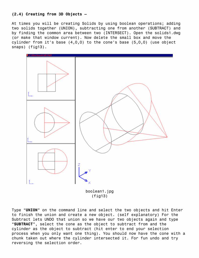
(2.4) Creating from 3D Objects – At times you will be creating Solids by using boolean operations; adding two solids together (UNION), subtracting one from another (SUBTRACT) and by finding the common area between two (INTERSECT). Open the solids1.dwg (or make that window current). Now delete the small box and move the cylinder from it’s base (4,0,0) to the cone’s base (5,0,0) (use object snaps) (fig13).
boolean1.jpg (fig13)
Type “UNION” on the command line and select the two objects and hit Enter to finish the union and create a new object. (self explanatory) For the Subtract lets UNDO that union so we have our two objects again and type “SUBTRACT”, select the cone as the object to subtract from and the cylinder as the object to subtract (hit enter to end your selection process when you only want one thing). You should now have the cone with a chunk taken out where the cylinder intersected it. For fun undo and try reversing the selection order.

(2.4) Creating from 3D Objects – (continued) Now lets create a new solid from the Intersection of our cylinder and cone. Again undo back to the cylinder and cone as separate objects, and type “INTERSECT” and select the two objects and hit Enter to end the selection process and see your new solid. Your solids should look like the ones in (fig14) below. (Again if I were you I would save (solids3.dwg) so I could come back and review later)
boolean2.jpg (fig14)
In Conclusion – Remember you can always project 2D views from 3D solids using SOLPROF so you should never have to draw in 2D again :o)) just kidding but do practice these basic exercises. Also be sure to start a collection of your common 3D objects so you only create them once.