Autodesk Building Systems 2004 Features and Benefits
33
www.autodesk.com/buildingsystems 1 Autodesk Building Systems 2004 Autodesk ® Building Systems 2004 offers an easier way to design and document mechanical, electrical, plumbing, and fire protection systems. It provides engineering-specific design features for increased productivity and accuracy; object-based modeling technology and drawing management tools for improved coordination of construction documents and project data; and extensive libraries of international content and content-creation tools for the design of complex MEP systems. Key Features and Benefits Ensure Coordination with Intelligent Engineering Objects—System-based rules, parametric content, and intelligent documentation routines, such as schedules, sections, and elevations, ensure that every design is well coordinated with your construction documents. Modify the sizing of a duct, and the transitions change accordingly. Sections, elevations, and schedules can also be updated automatically, under your control. Save Time with Automated Management Routines—Autodesk Building Systems gives you more time for design and solving real MEP engineering problems by providing tools such as the Display Manager, Layer Manager, and Drawing Manager to reduce the tedium of CAD management. These tools accurately manage views, layers, and project organization, so you can stay focused on design. Draft Accurately with Engineering-Specific Tools—Whether you are designing in 2D or 3D, you are creating a building model that dynamically links all design changes. That means your team is always working with the most current design data ensuring high-quality construction documents and full coordination of engineering documentation. Design Efficiently with Data-Rich Content—Autodesk Building Systems provides an extensive library of content as well as access to manufacturer content. You can even create custom content using catalog editors and parametric content builder routines to make meeting your design requirements easier than ever. Collaboration: Work Effectively with Your Extended Design Team—Because Autodesk Building Systems is interoperable with other applications from Autodesk and from independent developers, you can be sure that extensive solutions are available for you and your extended design team to get your project done efficiently. This wide variety of solutions enables you to extract vital information from your data-rich building systems design that can be used to save time and money during analysis, estimating, procurement, construction, and management of the building throughout its lifecycle—building lifecycle management. Features and Benefits
Transcript of Autodesk Building Systems 2004 Features and Benefits

www.autodesk.com/buildingsystems 1
Autodesk Building Systems 2004
Autodesk® Building Systems 2004 offers an easier way to design and document mechanical, electrical, plumbing, and fire protection systems. It provides engineering-specific design features for increased productivity and accuracy; object-based modeling technology and drawing management tools for improved coordination of construction documents and project data; and extensive libraries of international content and content-creation tools for the design of complex MEP systems.
Key Features and Benefits Ensure Coordination with Intelligent Engineering Objects—System-based rules, parametric content, and intelligent documentation routines, such as schedules, sections, and elevations, ensure that every design is well coordinated with your construction documents. Modify the sizing of a duct, and the transitions change accordingly. Sections, elevations, and schedules can also be updated automatically, under your control.
Save Time with Automated Management Routines—Autodesk Building Systems gives you more time for design and solving real MEP engineering problems by providing tools such as the Display Manager, Layer Manager, and Drawing Manager to reduce the tedium of CAD management. These tools accurately manage views, layers, and project organization, so you can stay focused on design.
Draft Accurately with Engineering-Specific Tools—Whether you are designing in 2D or 3D, you are creating a building model that dynamically links all design changes. That means your team is always working with the most current design data ensuring high-quality construction documents and full coordination of engineering documentation.
Design Efficiently with Data-Rich Content—Autodesk Building Systems provides an extensive library of content as well as access to manufacturer content. You can even create custom content using catalog editors and parametric content builder routines to make meeting your design requirements easier than ever.
Collaboration: Work Effectively with Your Extended Design Team—Because Autodesk Building Systems is interoperable with other applications from Autodesk and from independent developers, you can be sure that extensive solutions are available for you and your extended design team to get your project done efficiently. This wide variety of solutions enables you to extract vital information from your data-rich building systems design that can be used to save time and money during analysis, estimating, procurement, construction, and management of the building throughout its lifecycle—building lifecycle management.
Features and Benefits

Autodesk Building Systems 2004 Features and Benefits
www.autodesk.com/buildingsystems 2
The following tables outline the new features and enhancements for Autodesk Building Systems 2004. In addition, a side-by-side comparison shows whether these features are available in AutoCAD® 2002, Autodesk® Building Systems 3, and AutoCAD® 2004.
Legend:
New Feature
Enhanced Feature
Available Feature
Unavailable Feature
General Product Information: Tools That Enhance Ease of Use Product Comparison Feature
Function Benefit
Au
toC
AD
20
02
Au
tod
esk
Bu
ild
ing
S
yst
em
s 3
Au
toC
AD
20
04
Au
tod
esk
Bu
ild
ing
S
yst
em
s 2
00
4
Tool Palettes Tool palettes give you instant access to a complete inventory of stock Autodesk Building Systems tools such as ducts, pipes, schematic lines, schedules, cable tray, and conduit in one consistent user interface. Tool palettes include a preview of each style.
Highly visual and customizable, tool palettes provide centralized access to your commonly used project-based design tools, thus enhancing productivity.
Content Browser The new Content Browser is a central repository for project-based tools and content, such as catalogs, tool palettes, blocks, and Multiview Parts.
The Content Browser provides a central location to disseminate project-based information, ensuring that every member of your design team has access to the most up-to-date tools.

Autodesk Building Systems 2004 Features and Benefits
www.autodesk.com/buildingsystems 3
General Product Information: Tools That Enhance Ease of Use Product Comparison Feature
Function Benefit
Au
toC
AD
20
02
Au
tod
esk
Bu
ild
ing
S
yst
em
s 3
Au
toC
AD
20
04
Au
tod
esk
Bu
ild
ing
S
yst
em
s 2
00
4
Drawing Management
Create projects, manage levels, and automate sheet creation from a centralized project environment.
Drawing management tools ensure consistency throughout all aspects of the project. You can be assured that everyone on your design team is accessing the most current documents— from project templates to sections and elevations—from a centralized location.
Drawing Window Status Bar
The Drawing Window status bar provides heads-up access to pertinent information and tools for each drawing.
The user interface has been streamlined into highly focused areas of all-purpose drawing tools, providing a fluid design environment that enhances your productivity and improves efficiency.
Style Manager The Style Manager enables you to create, define, or modify all AEC object styles through a single, centralized interface.
Manage your content, share formatting, and access key features all from a centralized location. Avoid the same mundane activities by dragging and dropping styles between your documents. Style Manager helps you maintain company standards by enabling you to post standardized content that is accessible to everyone using Autodesk Building Systems.

Autodesk Building Systems 2004 Features and Benefits
www.autodesk.com/buildingsystems 4
General Product Information: Tools That Enhance Ease of Use Product Comparison Feature
Function Benefit
Au
toC
AD
20
02
Au
tod
esk
Bu
ild
ing
S
yst
em
s 3
Au
toC
AD
20
04
Au
tod
esk
Bu
ild
ing
S
yst
em
s 2
00
4
Display Manager The Display Manager enables you to quickly change the display of your designs. Through a centralized location, you can easily manipulate building objects to display differently for various plotting needs, without layer manipulation.
Display Manager enables you to create all your construction drawings from a single model. Change the view and a demolition floor plan becomes a final ductwork layout plan. Change the view again and it becomes an isometric schematic layout. Save time and effort by drawing once. And, since each view is based on the same model all your construction drawings reflect the same design. Any change you make is immediately and accurately propagated throughout all the views.
Layer Manager Autodesk Building Systems enhances AutoCAD software’s native Layer Manager with its own set of tools for layer standardization. In Autodesk Building Systems, layers are automatically created as you draw.
The Layer Manager enables you to manage design data based on industry or company layer standards, for more efficient CAD management. Since Autodesk Building Systems manages layers, you can be confident that everything you draw goes on the correct layer, ensuring the accuracy of your designs.

Autodesk Building Systems 2004 Features and Benefits
www.autodesk.com/buildingsystems 5
General Product Information: Tools That Enhance Ease of Use Product Comparison Feature
Function Benefit
Au
toC
AD
20
02
Au
tod
esk
Bu
ild
ing
S
yst
em
s 3
Au
toC
AD
20
04
Au
tod
esk
Bu
ild
ing
S
yst
em
s 2
00
4
Object Viewer Isolate part of your building model with real-time shaded, hidden, or wireframe displays, and determine drawing views based on your settings.
Explore designs with instant visual feedback. Avoid costly changes in the field by making sure what was drawn actually fits in the space it was designed for.
AEC Content Wizard
Create customized AEC content with layer, attribute, scale, and insertion information that meets your office standards.
Customized library of content adheres to your office standards, saving time and helping to ensure accuracy.

Autodesk Building Systems 2004 Features and Benefits
www.autodesk.com/buildingsystems 6
Project Setup: Establish Office Standards and Reduce Rework Product Comparison Feature Function Benefit
Au
toC
AD
20
02
Au
tod
esk
Bu
ild
ing
S
yst
em
s 3
Au
toC
AD
20
04
Au
tod
esk
Bu
ild
ing
S
yst
em
s 2
00
4
System Definitions
Assign system preferences based on styles created in the Style Manager for ductwork, piping, plumbing, electrical, and schematics.
Establishing system definitions enables you to concentrate more on your design and less on drafting. Because you don’t have to establish drafting standards for every drawing session, cycle times are faster and you can handle more projects.
Navigation Compass
The compass aids with the routing of ductwork and piping in 2D and 3D.
The compass helps you layout building systems using commonly available parts. Angle snaps that automate precise layouts free you to focus on design. And, the compass frees you from worrying about the user coordinate system (UCS).
Linked Labeling Routines
The Label dialog box has a new look and feel that makes labeling fast and easy. You can automatically label ductwork, piping, cable tray, conduit, and more as objects are drawn or inserted into the drawing. Labels automatically update when their linked perspective objects are changed.
Linked labeling assists in quality control of your drawings as they change throughout the design process.

Autodesk Building Systems 2004 Features and Benefits
www.autodesk.com/buildingsystems 7
Project Setup: Establish Office Standards and Reduce Rework Product Comparison Feature Function Benefit
Au
toC
AD
20
02
Au
tod
esk
Bu
ild
ing
S
yst
em
s 3
Au
toC
AD
20
04
Au
tod
esk
Bu
ild
ing
S
yst
em
s 2
00
4
Building Systems Object Snaps
Building Systems Object Snaps eliminate the need to find just the right object snap for a particular drafting task. The snaps automatically find the connection points you need to complete your design.
Building Systems Object Snaps make for precise locations and quick connections, so you can complete your design faster.
Duct and Pipe Preferences
Layout preferences enable you to select parts from the catalog to use while laying out duct and pipe.
Save time and reduce errors in layouts by having your preferred fittings automatically insert as you draw duct and pipe. Design faster and eliminate manual time consuming tasks using Autodesk Building Systems.
Building Systems Options Tabs
Options tabs give you an easy way to customize your software settings.
Quickly and easily establish office standards to reduce rework, saving time and money.
Templates Content-rich templates provide a comprehensive foundation for your designs.
Adopt template settings and modify them to your company standards so that all drawings have the same look, reducing time spent correcting mistakes associated with office protocol.

Autodesk Building Systems 2004 Features and Benefits
www.autodesk.com/buildingsystems 8
Mechanical Design: Enhance Productivity Product Comparison Feature
Function Benefit
Au
toC
AD
20
02
Au
tod
esk
Bu
ild
ing
S
yst
em
s 3
Au
toC
AD
20
04
Au
tod
esk
Bu
ild
ing
S
yst
em
s 2
00
4
Ductwork
Autodesk Building Systems software facilitates ductwork routing as single line, 2D, or 3D by adding preferred fittings automatically.
By automating much of the ductwork design, you can increase productivity, which puts money back in your pocket. And because you are creating an object instead of a series of unrelated lines, arcs, and circles, modifying your design has never been easier. As a result, you can spend more time designing and less time solving unnecessary problems.
Duct Fitting
The most commonly used duct fittings are automatically inserted as you design your ductwork, avoiding time-consuming interruptions. You can use the Add Duct Fitting command to add fittings such as bull-head tees, pant-legs, end caps, and wyes.
Because duct fittings are based on industry standards, you get a ductwork design that models a real-world installation, reducing errors and minimizing project design time.
Flex Duct
Complete a duct run or connect an air handler to the rest of the ductwork system using flexible duct. Because flexible duct is a 3D object, you can take advantage of interference detection, making it easier to coordinate ductwork, piping, and electrical systems.
Flexible duct enables you to accurately reflect your design intent and complete your model eliminating interferences that can lead to costly changes in the field.

Autodesk Building Systems 2004 Features and Benefits
www.autodesk.com/buildingsystems 9
Mechanical Design: Enhance Productivity Product Comparison Feature
Function Benefit
Au
toC
AD
20
02
Au
tod
esk
Bu
ild
ing
S
yst
em
s 3
Au
toC
AD
20
04
Au
tod
esk
Bu
ild
ing
S
yst
em
s 2
00
4
Piping
Intuitive design tools help you create entire chilled water, hot water, steam, fire protection, or other piping systems in single line, 2D, or 3D, and provide time-saving enhancements like auto-routing.
All piping uses object-based technology, giving you a data-rich model of the mechanical piping system. The result is more accurate piping design, which reduces errors and decreases costs.
Pipe Fitting
Autodesk Building Systems automatically inserts pipe fittings while you draw. To place a specific fitting such as a tee, a coupling, a cross, an end cap, or a takeoff, use the Add Pipe Fitting command. These fittings are based on industry standards and include a wide range of connection types: flanged, socket welded, threaded, and more.
All pipe fittings and connections are based on industry standards, creating a more accurate building model that minimizes costly change orders during construction.
Flex Pipe
Use flexible pipe to make the connection to a hard-to-reach cooling coil or simply isolate a pump from the rest of the piping system.
Flexible pipe enables you to accurately reflect your design intent and complete your model eliminating interferences that can lead to costly changes in the field.
Mechanical Equipment
Autodesk Building Systems provides a series of 2D and 3D multiview blocks (MvParts) with enhanced properties. You can retrieve industry-specific equipment from the catalogs and integrate it into your design.
Catalogs offer an innovative approach to identifying, viewing, and inserting equipment, which helps with the early stages of design. You can then query this equipment to assist with labeling and scheduling or store custom parts for future use.

Autodesk Building Systems 2004 Features and Benefits
www.autodesk.com/buildingsystems 10
Mechanical Design: Enhance Productivity Product Comparison Feature
Function Benefit
Au
toC
AD
20
02
Au
tod
esk
Bu
ild
ing
S
yst
em
s 3
Au
toC
AD
20
04
Au
tod
esk
Bu
ild
ing
S
yst
em
s 2
00
4
Turning Vanes
You can add turning vanes to duct elbows quickly and easily with fewer commands and more versatility.
The ability to easily add turning vanes to ductwork elbows helps reduce drafting time and cut production costs.
Create Custom Duct and Pipe Fittings
Create custom duct and pipe fittings by using simple AutoCAD lines, arcs, and circles.
The ability to create custom duct and pipe fittings enables you to tailor your designs to meet the facility’s requirements.
Takeoffs Takeoffs can be placed anywhere on a duct of pipe trunk and at any orientation.
No more worrying about the limitations of CAD software affecting your design. Layout duct systems that are aligned to ceilings, walls and other structure just as in real-life.
Top of Duct and Bottom of Duct Labeling
Easily label the top or bottom of duct elevations.
Engineers and contractors need to know top of duct and bottom of duct elevations. Save valuable time by eliminating the need to calculate these elevations manually.
Lock Elevation Lock elevation of a duct or pipe takeoff to simplify connecting to a duct or pipe riser.
Creating takeoffs from duct and pipe risers has never been easier. Locking a duct or pipe elevation makes it easier to create a branch from a riser, saving you time by eliminating tedious drafting tasks.

Autodesk Building Systems 2004 Features and Benefits
www.autodesk.com/buildingsystems 11
Mechanical Design: Enhance Productivity Product Comparison Feature
Function Benefit
Au
toC
AD
20
02
Au
tod
esk
Bu
ild
ing
S
yst
em
s 3
Au
toC
AD
20
04
Au
tod
esk
Bu
ild
ing
S
yst
em
s 2
00
4
Fire Protection New fire protection content helps you lay out fire protection piping, sprinkler heads, fire pumps, and control valves for a more complete building information model.
With fire protection content now available, you can eliminate conflicts between fire protection piping and other engineering systems, reducing the number of costly change orders during the construction phase.
Suggested Layout Path
When two existing runs of duct, pipe, cable tray, or conduit need to be connected, pick on the ends that need to be joined and let the software do the rest. This works in plan or 3D mode and on objects with different X, Y, and even Z coordinates.
Increase your design productivity by letting Autodesk Building Systems automatically route duct, pipe, conduit, and cable tray between two known points.

Autodesk Building Systems 2004 Features and Benefits
www.autodesk.com/buildingsystems 12
Plumbing Design: Enhance Productivity Product Comparison Feature
Function Benefit
Au
toC
AD
20
02
Au
tod
esk
Bu
ild
ing
S
yst
em
s 3
Au
toC
AD
20
04
Au
tod
esk
Bu
ild
ing
S
yst
em
s 2
00
4
Plumbing Fixtures and Equipment
This capability provides 2D/3D multiview blocks with enhanced properties that assist with labeling and scheduling. Large catalogs ensure that you have the fixtures and equipment you need to complete designs. Customizable fixture unit tables provide the parameters to drive plumbing pipe sizing calculations provided in the product.
Smart plumbing fixtures enable you to design, size, and meet code requirements while you draw. Save time and increase your confidence in your design by integrating design and drawing.
Plumbing Piping
Plumbing systems enable you to specify system settings on-the-fly such as size, slope, system, elevation, and material to help you manage your design.
Minimize production time by using plumbing systems to assure that your design has the right fittings, the correct layout, and the correct display automatically as you draw.
Plumbing Fittings
Fittings are automatically inserted from your list of preferred parts as you draw plumbing layouts.
Fittings automatically trim and align themselves properly to the piping, eliminating tedious drafting tasks.
Pipe Sizing Table Definitions
The pipe sizing tables provide a convenient way to deliver code-driven requirements for sizing connected pipe runs to fixtures. You can customize these tables or create new ones.
Building code requirements built right into the application automate the sizing of plumbing systems. You increase productivity by eliminating the need to look up sizes in plumbing code manuals.

Autodesk Building Systems 2004 Features and Benefits
www.autodesk.com/buildingsystems 13
Plumbing Design: Enhance Productivity Product Comparison Feature
Function Benefit
Au
toC
AD
20
02
Au
tod
esk
Bu
ild
ing
S
yst
em
s 3
Au
toC
AD
20
04
Au
tod
esk
Bu
ild
ing
S
yst
em
s 2
00
4
Fixture Unit Table Definition
Each fixture has a unit property associated with it. Fixture units are stored in tables that you can modify, add to, copy – or you can start from scratch. You can customize these tables to match the plumbing code that your design requires.
Drastically reduce time spent thumbing through code manuals trying to find the appropriate fixture unit values for your design. Having them incorporated into your drawing makes sizing your plumbing systems much faster while maintaining the integrity of your design.
Plumbing Pipe Sizing
Size plumbing piping based on built-in pipe sizing tables. Sizing routines are also available as stand-alone calculators.
Focus on design while letting Autodesk Building Systems help you with the mundane activities of sizing your plumbing systems.
Expansion Loop
Easily create expansion loops in your piping systems using the Add Pipe Expansion Loop command.
By using a step-by-step process, you can create an expansion loop quickly and easily, without extra drafting.
Elevation Label
Label various points along your piping system that give the related elevation information.
Quickly tag critical points along your sanitary sewer piping system with invert elevation information, eliminating time spent on manual calculations.

Autodesk Building Systems 2004 Features and Benefits
www.autodesk.com/buildingsystems 14
Plumbing Design: Enhance Productivity Product Comparison Feature
Function Benefit
Au
toC
AD
20
02
Au
tod
esk
Bu
ild
ing
S
yst
em
s 3
Au
toC
AD
20
04
Au
tod
esk
Bu
ild
ing
S
yst
em
s 2
00
4
Slope of Pipe The plumbing module automatically calculates the slope of your plumbing piping based on rise/run values that you provide.
Save time calculating slopes and elevations of critical points in your plumbing piping systems by letting Autodesk Building Systems do it for you on the fly.
3D Plumbing Piping
Create 3D plumbing layouts for domestic cold water and sanitary sewer to help complete your plumbing systems design.
With 3D plumbing piping, you can use interference detection to locate costly collisions with components of other engineering systems to improve documentation accuracy and minimize errors.
Rise/Drop Tees This new schematic piping preference enables you to properly denote changes in elevation in your 2D schematic designs.
This option helps you create more accurate plumbing designs.

Autodesk Building Systems 2004 Features and Benefits
www.autodesk.com/buildingsystems 15
Electrical Design: Enhance Productivity Product Comparison Feature
Function Benefit
Au
toC
AD
20
02
Au
tod
esk
Bu
ild
ing
S
yst
em
s 3
Au
toC
AD
20
04
Au
tod
esk
Bu
ild
ing
S
yst
em
s 2
00
4
Electrical Devices
Electrical devices represent items like lighting fixtures, switches, and receptacles. You can view an electrical device as a symbol in plan view or as a 3D intelligent object in model view. Smart connectors, on each device know how and where they are connected.
Devices enable you to work in 2D but automatically produce 3D representations of the objects in the design. Connectors prevent errors by restricting connection of devices to systems for which they are appropriate and automatically setting sizes and other parameters, as appropriate.
Panels
Panels are used for grouping and creating circuits in your electrical design. Panel properties are also used in the creation of panel schedules.
Panels enable you to quickly and easily create panel schedules to document the electrical component of your design.

Autodesk Building Systems 2004 Features and Benefits
www.autodesk.com/buildingsystems 16
Electrical Design: Enhance Productivity Product Comparison Feature
Function Benefit
Au
toC
AD
20
02
Au
tod
esk
Bu
ild
ing
S
yst
em
s 3
Au
toC
AD
20
04
Au
tod
esk
Bu
ild
ing
S
yst
em
s 2
00
4
Circuits
Circuits track properties such as load, number of attached devices, and length. Circuits connect devices to panels, with or without wiring. Circuits can be defined as single, two, or three poles; each can have a voltage associated with it. Circuits automatically flag overload situations when too many devices are connected.
Autodesk Building Systems ensures accuracy while you design electrical systems, reducing steps in the design process. Optional wiring display helps you avoid clutter for clearer construction documents. You can design circuits using multipole connections to reflect actual designs, helping you to make your construction documents as accurate as possible. You can assign wiring to more than one circuit, to show multiple circuits in a single wiring run (with multiple home run arrows) simplifying drawings and making you faster. Automatic prompts reduce mistakes by notifying you of potential overloads as they occur, helping you avoid errors and rework.
Circuit Manager
The Circuit Manager enables you to add, modify, and delete circuits in the drawing. It also serves as the central location for editing panel schedule data such as description and rating. Any overloaded circuit appears highlighted in red.
Circuit Manager enables you to work more efficiently by giving you a single location to manage and edit circuit information. Automatic prompts notify you of potential overloads as they occur, helping you avoid errors and rework.

Autodesk Building Systems 2004 Features and Benefits
www.autodesk.com/buildingsystems 17
Electrical Design: Enhance Productivity Product Comparison Feature
Function Benefit
Au
toC
AD
20
02
Au
tod
esk
Bu
ild
ing
S
yst
em
s 3
Au
toC
AD
20
04
Au
tod
esk
Bu
ild
ing
S
yst
em
s 2
00
4
Panel Schedules
Create panel schedules from intelligent electrical systems with a click of the mouse.
Links between the systems and the panel schedules ensure that these schedules are always up-to-date and accurate.
Functions that generate panel schedules are written in VBA (Visual Basic® for Applications) so that you can customize their look and functionality. You can create panel schedules in the drawing or export them to Microsoft® Excel. Use bidirectional functionality to directly update your design in Excel.
Panel schedules automatically coordinate your construction documents, helping you avoid mistakes and rework.
Panel schedules are more versatile and easier to use, so you can complete construction documents to your standards.
Voltage Definitions
Set up voltage definitions for single, two-, and three-pole configurations. The voltage definitions include ranges that are used to test connections to make sure connecting systems and devices are compatible.
Voltage definitions help eliminate mistakes in circuiting, ensuring a fully coordinated, well-documented design.

Autodesk Building Systems 2004 Features and Benefits
www.autodesk.com/buildingsystems 18
Electrical Design: Enhance Productivity Product Comparison Feature
Function Benefit
Au
toC
AD
20
02
Au
tod
esk
Bu
ild
ing
S
yst
em
s 3
Au
toC
AD
20
04
Au
tod
esk
Bu
ild
ing
S
yst
em
s 2
00
4
Circuit Naming Preferences
The circuit naming preference enables you to specify how to name circuits as they are created. You can select simple numbered circuits, use the panel name as a prefix, or create a custom prefix for circuit names.
Circuit naming preferences enable you to automatically name circuits according to the building standard, avoiding confusion in the field during construction.
Wiring
Wiring enables you to show connections between lighting fixtures, receptacles, switches, and other devices and panels. Because the wire is intelligent, it automatically creates a circuit, enabling you to perform a circuit analysis and generate schedules with a few mouse clicks. Annotation of wiring is flexible, with an extensive set of tools to control tick marks, ground symbols, and line types.
Wiring between devices and panels enables you to quickly make construction documents that show connectivity.
Wiring assists with the coordination of data, helping you to avoid costly errors. Wiring also “monitors” the number of circuits connected and shows the home runs associated with those connections.
Display wiring in accordance with your office standards, saving time and eliminating confusion.
Circuit Analysis Tools
The Circuit Info, Circuit Report, and Power Totals tools provide quick and easy access to data in your design.
You can quickly total loads and generate reports for easy and accurate documentation.

Autodesk Building Systems 2004 Features and Benefits
www.autodesk.com/buildingsystems 19
Electrical Design: Enhance Productivity Product Comparison Feature
Function Benefit
Au
toC
AD
20
02
Au
tod
esk
Bu
ild
ing
S
yst
em
s 3
Au
toC
AD
20
04
Au
tod
esk
Bu
ild
ing
S
yst
em
s 2
00
4
Connector Property Presets and Override Prevention
Connectors enable you to “preset” default values, as well as lock the values. The presets and locks can be applied either in the current drawing or in external content.
By using preset electrical connector properties, you can create better-coordinated designs faster and with fewer mistakes.
Demand Factor Styles
Using Demand Factor Styles, you can calculate the estimated demand load on feeders and panels throughout your electrical design.
Easy access to information on estimated demand load helps you size feeders and panels quickly and efficiently.
Insert Properly Annotated Devices
Select the right label to be inserted automatically when a device is created. Define an “annotation block” that becomes part of the device.
Pick from a selection of labels or design your own to make sure your construction drawings accurately display your designs.

Autodesk Building Systems 2004 Features and Benefits
www.autodesk.com/buildingsystems 20
Electrical Design: Enhance Productivity Product Comparison Feature
Function Benefit
Au
toC
AD
20
02
Au
tod
esk
Bu
ild
ing
S
yst
em
s 3
Au
toC
AD
20
04
Au
tod
esk
Bu
ild
ing
S
yst
em
s 2
00
4
Cable Tray and Conduit
This feature helps you lay out conduit and cable tray in 3D, suggests layouts, inserts needed fittings, maintains angles via a compass, and provides snaps unique to Autodesk Building Systems to help you create your building model quickly. You can lay out conduit and cable tray in single line, 2D, or 3D. Additional fittings to both conduit and cable tray enable you to create more complete designs.
Lay out conduit and cable tray in 3D as fast as you used to in 2D. Increase your productivity by letting Autodesk Building Systems help you route conduit, and cable tray using preferred parts in seconds. Save time by creating the model once and producing many different construction drawings by simply changing your view of the model. You can continue to work with cable tray and conduit in “plan” or 2D mode, but support the building model concept by adding 3D data to the drawing. In this way, you can take full advantage features such as interference detection to reduce errors and avoiding costly design mistakes that are later found in the field.
Cable Tray and Conduit Run Modification
Modify a cable tray or conduit run using a catalog of parts. Watch as the system adapts, redrawing itself to the new, proper size based on your preferences.
Save time redrawing sized systems. Autodesk Building Systems automatically resizes systems based on your preferences.
Annotated Cable Tray and Conduit
Define which label(s) to insert automatically when a cable tray or conduit is created.
Properly annotate your electrical systems as you draw them, saving steps and valuable time.

Autodesk Building Systems 2004 Features and Benefits
www.autodesk.com/buildingsystems 21
Electrical Design: Enhance Productivity Product Comparison Feature
Function Benefit
Au
toC
AD
20
02
Au
tod
esk
Bu
ild
ing
S
yst
em
s 3
Au
toC
AD
20
04
Au
tod
esk
Bu
ild
ing
S
yst
em
s 2
00
4
Electrical Equipment
Autodesk Building Systems provides a series of 2D and 3D multiview blocks (MvParts) with enhanced properties. You can retrieve industry-specific equipment from the catalogs and integrate it into your design.
Catalogs offer an innovative approach to identifying, viewing, and inserting equipment, which helps with the early stages of design. You can then query this equipment to assist with labeling and scheduling, or store custom parts for future use.

Autodesk Building Systems 2004 Features and Benefits
www.autodesk.com/buildingsystems 22
Design (Common): Enhance Productivity Product Comparison Feature
Function Benefit
Au
toC
AD
20
02
Au
tod
esk
Bu
ild
ing
S
yst
em
s 3
Au
toC
AD
20
04
Au
tod
esk
Bu
ild
ing
S
yst
em
s 2
00
4
Schematic Tools
These tools enable you to quickly produce schematic diagrams with intelligent schematic lines and symbols, without the hassles of trimming lines and rotating blocks.
Save time and money by drawing your schematics faster.
Schematic Symbol Creation and Customization
Convert your own schematic symbols to “intelligent” schematic symbols that interact with Autodesk Building Systems schematic lines.
Save time by using familiar symbology.
Isometric Schematic Diagrams
Create isometric schematic diagrams by changing to the appropriate working iso-plane using icons in the Add Schematic Lines and Add Schematic Symbols dialog boxes.
Fewer steps are needed to create accurate isometric riser diagrams.
Intelligent Modification Tools
Modify any building systems object using intelligent modification tools.
Because building systems objects behave intelligently, you can make modifications quickly and easily. Labels, schedules, and sections update automatically, saving you time and money.

Autodesk Building Systems 2004 Features and Benefits
www.autodesk.com/buildingsystems 23
Design (Common): Enhance Productivity Product Comparison Feature
Function Benefit
Au
toC
AD
20
02
Au
tod
esk
Bu
ild
ing
S
yst
em
s 3
Au
toC
AD
20
04
Au
tod
esk
Bu
ild
ing
S
yst
em
s 2
00
4
Hidden Line Display
You can automatically depict crossed objects using dashed or Hidden Lines. Since these lines are controlled by the display system, they dynamically update with any changes to other building systems objects. Since Hidden Lines now work across x-refs, they are able to fully display in the building model set up through the Drawing Management feature.
Hidden Lines enable you to show your crossed duct, pipe, cable tray and conduit systems and their associated fixtures, lights, and other building systems objects as dashed lines without manually adding dashed lines. And because Hidden Lines update dynamically, they reflect any change in the drawing making you more efficient and avoiding annotation mistakes.
Interference Detection
Using ObjectARX® technology, Autodesk Building Systems can highlight interferences between objects in the same drawing or through xrefs, making it easier to locate collisions between building systems objects and structural members. Interference detection is part of the building model set up through the drawing management feature.
Intelligent feedback, like interference detection, increases design accuracy, minimizing costly errors.
Add Selected
Duplicate existing objects in the design.
The ability to quickly create new objects using existing components increases design productivity.

Autodesk Building Systems 2004 Features and Benefits
www.autodesk.com/buildingsystems 24
Design (Common): Enhance Productivity Product Comparison Feature
Function Benefit
Au
toC
AD
20
02
Au
tod
esk
Bu
ild
ing
S
yst
em
s 3
Au
toC
AD
20
04
Au
tod
esk
Bu
ild
ing
S
yst
em
s 2
00
4
Rise/Drop Symbology
Accurately represent rises and drops in duct, pipe, plumbing pipe, conduit, and cable tray.
The closer your construction documentation portrays your design intent, the fewer problems contractors have installing systems. That equates to fewer phone calls and headaches during construction for the engineer and owner.
Smart Connectors
Smart connectors allow building systems objects to transfer information from one another, making modifications to systems easier. You can also specify criteria to determine their connectivity to other objects.
Smart connectors make modeling easier so you can complete the design quickly.
MvPart Builder As part of the new Content Builder, the enhanced MvPart Builder can now turn your blocks into intelligent objects with minimal effort and time.
Make true-to-life model based parts in just a few minutes now that much of the tedious activities are automated. Model-based equipment and parts can increase design accuracy and help you avoid costly change orders during construction.
Parametric Content Creation
Use the Content Builder to create parametric MvParts and fittings by modeling a single size of the part and then specifying constraints that control how the part resizes.
The parametric content creation tools save you valuable time by enabling you to create libraries of equipment and fittings that generate hundreds of sizes from one model.

Autodesk Building Systems 2004 Features and Benefits
www.autodesk.com/buildingsystems 25
Design (Common): Enhance Productivity Product Comparison Feature
Function Benefit
Au
toC
AD
20
02
Au
tod
esk
Bu
ild
ing
S
yst
em
s 3
Au
toC
AD
20
04
Au
tod
esk
Bu
ild
ing
S
yst
em
s 2
00
4
Segment Length Control
Specify a maximum length for duct, pipe, conduit, or cable tray sections. The length of the object’s sections can be less than the specified length based on the geometry of the layout.
Save valuable time performing takeoffs for your engineering systems by controlling segment lengths as you design. Take advantage of dynamic scheduling and create a bill of materials that automatically updates as your design does.
U.S. Metric Content
Autodesk Building Systems features a rich catalog library of duct, pipe, cable tray, conduit, and equipment that conforms to guidelines set by the United States General Services Administration (GSA) for the metric system
In addition to providing metric-based content that satisfies the needs of the U.S. market, Autodesk Building Systems also serves as a solid foundation for a more focused metric catalog where standards differ from GSA guidelines.
U.K. Content Autodesk Building Systems 2004 includes a rich content library of catalog parts, devices, and schematics that are formatted for the U.K. market and meet British standards.
Customers working on projects in the U.K. can increase their productivity through the availability of content based on local design practices and standards.
Auto Insertion of Duct, Pipe, Plumbing, and Electrical Fittings
Duct and pipe fittings are automatically inserted as you draft based on the fittings you select in your preferences.
Because fittings are inserted automatically, you can concentrate on your design instead of on drafting tasks, increasing your design productivity.
Autodesk Building Systems 2004 Features and Benefits
www.autodesk.com/buildingsystems 26
Design (Common): Enhance Productivity Product Comparison Feature
Function Benefit
Au
toC
AD
20
02
Au
tod
esk
Bu
ild
ing
S
yst
em
s 3
Au
toC
AD
20
04
Au
tod
esk
Bu
ild
ing
S
yst
em
s 2
00
4
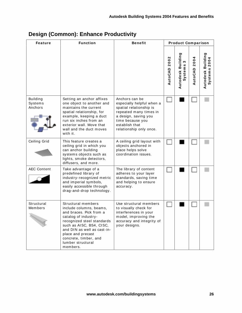
Building Systems Anchors
Setting an anchor affixes one object to another and maintains the current spatial relationship, for example, keeping a duct run six inches from an exterior wall. Move that wall and the duct moves with it.
Anchors can be especially helpful when a spatial relationship is repeated many times in a design, saving you time because you establish that relationship only once.
Ceiling Grid
This feature creates a ceiling grid in which you can anchor building systems objects such as lights, smoke detectors, diffusers, and more.
A ceiling grid layout with objects anchored in place helps solve coordination issues.
AEC Content
Take advantage of a predefined library of industry-recognized metric and imperial symbols, easily accessible through drag-and-drop technology.
The library of content adheres to your layer standards, saving time and helping to ensure accuracy.
Structural Members
Structural members include columns, beams, and braces. Pick from a catalog of industry-recognized steel standards such as AISC, BS4, CISC, and DIN as well as cast-in-place and precast concrete, timber, and lumber structural members.
Use structural members to visually check for interferences in your model, improving the accuracy and integrity of your designs.

Autodesk Building Systems 2004 Features and Benefits
www.autodesk.com/buildingsystems 27
Design (Common): Enhance Productivity Product Comparison Feature
Function Benefit
Au
toC
AD
20
02
Au
tod
esk
Bu
ild
ing
S
yst
em
s 3
Au
toC
AD
20
04
Au
tod
esk
Bu
ild
ing
S
yst
em
s 2
00
4
Slabs
Create a housekeeping pad under your mechanical, electrical, and plumbing equipment in mechanical and electrical rooms.
The flexibility of the slab routine gives you the ability to easily create concrete slabs that can be flat or sloped with edge styles for an even more realistic model that you can use as the basis for details, sections, and elevations.
i-drop® Technology
Autodesk Building Systems provides fast, simple access to additional content through i-drop. Whether part of the extensive content libraries provided with the product, created in-house and shared via your intranet, or retrieved from a manufacturer’s web site, i-drop functionality permits a fast, simple consistent means of accessing standard and custom content to increase your productivity.
Decrease content creation time by downloading the part you need straight from a manufacturer’s website or by maximizing reuse of parts created in-house. Getting the right part to the right people helps ensure design accuracy while minimizing time spent creating custom or duplicate content.

Autodesk Building Systems 2004 Features and Benefits
www.autodesk.com/buildingsystems 28
Documentation: Reduce Errors Product Comparison Feature Function Benefit
Au
toC
AD
20
02
Au
tod
esk
Bu
ild
ing
S
yst
em
s 3
Au
toC
AD
20
04
Au
tod
esk
Bu
ild
ing
S
yst
em
s 2
00
4
Sections and Elevations
Use sections and elevations to maintain dynamic links to your designs.
Style-based sections and elevations remain consistent throughout your building model. When you make a change in your design, sections and elevations update, saving time and ensuring the accuracy of your data.
Live Sections
Creates a “live” section view of your designs, complete with material hatching.
Live sections provide a good way to work on a limited area of a large model. Your design reflects each change in real time, eliminating tedious manual updates.
Schedules
Extract vital data from your design through schedule tables, in the drawing or through xrefs, and export them in various file formats such as Microsoft Excel for downstream uses. And now you can schedule equipment by type (for example, pump, diffuser, fan) to add more flexibility to your schedules.
Schedules are dynamically linked to your design data, automatically updating as your design changes thus reducing the chance for errors.

Autodesk Building Systems 2004 Features and Benefits
www.autodesk.com/buildingsystems 29
Documentation: Reduce Errors Product Comparison Feature Function Benefit
Au
toC
AD
20
02
Au
tod
esk
Bu
ild
ing
S
yst
em
s 3
Au
toC
AD
20
04
Au
tod
esk
Bu
ild
ing
S
yst
em
s 2
00
4
Schedule Tags
Tag diffusers, VAV boxes, pumps, lights, sinks, water heaters, receptacles, and more through xrefs and paper space and link them to your schedule tables.
Use predefined tags or create custom tags that contain dynamically updating information. Avoid manual coordination problem between drawings and schedules since these tags use the same information as the model. Avoid purchasing errors since they are always up-to-date.
Property Set Data
Property set data is intelligent data associated to your designs, including location information and calculations. You can display this information in both schedule tags and schedule tables.
Property set data is dynamic and attaches easily to building systems objects for scheduling purposes, saving you time.
Annotation Tags
Drag-and-drop tags for reference marks, titles, leaders, and revision clouds use automated annotation routines.
Save annotation time using tags that do the work for you.

Autodesk Building Systems 2004 Features and Benefits
www.autodesk.com/buildingsystems 30
Design Visualization: Bring Your Design Ideas to Life Product Comparison Feature
Function Benefit
Au
toC
AD
20
02
Au
tod
esk
Bu
ild
ing
S
yst
em
s 3
Au
toC
AD
20
04
Au
tod
esk
Bu
ild
ing
S
yst
em
s 2
00
4
VIZ Render, included in every box of Autodesk Building Systems, provides a simple but powerful rendering tool to build presentation quality images of your designs.
Get the renderings you need to win contracts, and impress clients through a powerful rendering tool that is fully integrated into the Autodesk Building Systems workflow.
• Interactive viewport for fast and direct feedback on material and lighting setup
• Global illumination rendering techniques, including radiosity and raytracing
• Support for physically based lighting
• New physically based material type
• Extensive catalog of predefined materials
• Support for natural daylight
• Lighting analysis tools
Extend the value of your building model for by using it to test lighting designs and running lighting design studies using both natural and artificial lighting.
VIZ Render
• Fast, high-quality scan-line rendering
• Photorealistic renderings using global illumination
• Walkthrough animation support
Capitalize on the building model to produce design presentations suitable for any stage of design development and marketing.
True Color/ Color Books Support
Choose from HSL, RGB, as well as PANTONE® and RAL color models.
Popular color palettes enhance your ability to create presentation-quality output.

Autodesk Building Systems 2004 Features and Benefits
www.autodesk.com/buildingsystems 31
Design Visualization: Bring Your Design Ideas to Life Product Comparison Feature
Function Benefit
Au
toC
AD
20
02
Au
tod
esk
Bu
ild
ing
S
yst
em
s 3
Au
toC
AD
20
04
Au
tod
esk
Bu
ild
ing
S
yst
em
s 2
00
4
Shaded Viewport Plotting
Plot shaded and rendered models from model space as well as paper space layouts.
Plotting shaded viewports gives you even more options for high-quality presentation graphics.
Perspectives
Adjustable cameras create perspective views of your designs. Perspectives created in Autodesk Building Systems automatically appear in VIZ Render for photorealistic renderings.
Avoid mundane and time consuming rendering set-ups since VIZ Render uses the same perspectives you set up in Autodesk Building Systems.

Autodesk Building Systems 2004 Features and Benefits
www.autodesk.com/buildingsystems 32
Collaboration: Work Effectively with Your Extended Design Team Product Comparison Feature Function Benefit
Au
toC
AD
20
02
Au
tod
esk
Bu
ild
ing
S
yst
em
s 3
Au
toC
AD
20
04
Au
tod
esk
Bu
ild
ing
S
yst
em
s 2
00
4
AutoCAD 2004 Support
Autodesk Building Systems saves native AutoCAD DWG files.
Since Autodesk Building Systems is built on the same technology as Autodesk® Architectural Desktop, it includes the latest version of AutoCAD so you have all AutoCAD software’s functionality, including enhancements to performance, plotting, file sharing, and license management, as well as Autodesk’s industry leading DWG compatibility, for seamless exchange of legacy drawing information.
Autodesk Architectural Desktop Support
Multidiscipline firms can use both Autodesk Architectural Desktop and Autodesk Building Systems for architectural, mechanical, plumbing, and electrical design.
Since Autodesk Architectural Desktop and Autodesk Building Systems use the same object technology, coordination among team members and design teams has never been easier within the complex building design process.
Autodesk® Buzzsaw™ Support
Autodesk Building Systems is integrated with the Autodesk Buzzsaw online project collaboration service, enabling you to share drawings and documents, and support project team communications - all in one central and secure online location.
Easily access and distribute your drawings with the user-friendly direct link to your Autodesk Buzzsaw site.

Autodesk Building Systems 2004 Features and Benefits
www.autodesk.com/buildingsystems 33
Collaboration: Work Effectively with Your Extended Design Team Product Comparison Feature Function Benefit
Au
toC
AD
20
02
Au
tod
esk
Bu
ild
ing
S
yst
em
s 3
Au
toC
AD
20
04
Au
tod
esk
Bu
ild
ing
S
yst
em
s 2
00
4
Autodesk Professional Services
Autodesk Professional Services provides integrated consulting, training, and support to help you get the full benefit from your investment in Autodesk technology.
Get help setting up, learning, and supporting your Autodesk software and achieve higher return on your technology investment.
Third-Party Support
Extensive third-party support addresses niche markets such as facilities management, cost estimations, and structural framing.
Customize data from Autodesk Building Systems with third-party solutions to suit your many design needs.
Autodesk, Inc. 111 McInnis Parkway San Rafael, CA 94903 USA
Autodesk, AutoCAD, Buzzsaw, i-drop, and ObjectARX are either registered trademarks or trademarks of Autodesk, Inc., in the USA and/or other countries. All other brand names, product names, or trademarks belong to their respective holders.
© 2003 Autodesk, Inc. All rights reserved.