AutoCAD® for MicroStation Users - AUGI · For comparison purposes, this seminar focuses on...
12
Walt Disney World Swan and Dolphin Resort Orlando, Florida 11/30/2005 - 8:00 am - 9:30 am Room:Peacock 2 (Swan) Come Back to the Other Side - AutoCAD® for MicroStation Users This session will demonstrate how experienced MicroStation users can transition to, or go back to working with AutoCAD. Many MicroStation users have experience working with AutoCAD at one time or another. Even if you have never used AutoCAD for production design, you probably have experience with an AutoCAD translation or conversion. This session will explore the fundamentals of working with AutoCAD including some of the latest enhancements. The last few AutoCAD releases have certainly turned my head. Come see what all the buzz is about! GD31-2 About the Speaker: Mark Mates - ProSoft Mark is the senior CAD instructor for ProSoft, conducting over 70 classes for CAD professionals annually. He specializes in providing project startup and workspace implementation for commercial and government organizations. Mark also serves as the primary technical writer, creating many of ProSoft's renowned CAD training manuals. Mark served in the U.S. Air Force for 10 years as an engineering technician. He then became a CAD manager for a large AE firm supporting over 100 MicroStation and AutoCAD architects and engineers. Mark is proficient in AutoCAD R7 - 2006, MicroStation V5 - V8 2004, and is a Microsoft Certified Systems Engineer [email protected]
Transcript of AutoCAD® for MicroStation Users - AUGI · For comparison purposes, this seminar focuses on...

Walt Disney World Swan and Dolphin ResortOrlando, Florida
11/30/2005 - 8:00 am - 9:30 am Room:Peacock 2 (Swan)
Come Back to the Other Side - AutoCAD® for MicroStation Users
This session will demonstrate how experienced MicroStation users can transition to, or go back to working with AutoCAD. Many MicroStation users have experience working with AutoCAD at one time or another. Even if you have never used AutoCAD for production design, you probably have experience with an AutoCAD translation or conversion. This session will explore the fundamentals of working with AutoCAD including some of the latest enhancements. The last few AutoCAD releases have certainly turned my head. Come see what all the buzz is about!
GD31-2
About the Speaker:
Mark Mates - ProSoft
Mark is the senior CAD instructor for ProSoft, conducting over 70 classes for CAD professionals annually. He specializes in providing project startup and workspace implementation for commercial and government organizations. Mark also serves as the primary technical writer, creating many of ProSoft's renowned CAD training manuals. Mark served in the U.S. Air Force for 10 years as an engineering technician. He then became a CAD manager for a large AE firm supporting over 100 MicroStation and AutoCAD architects and engineers. Mark is proficient in AutoCAD R7 - 2006, MicroStation V5 - V8 2004, and is a Microsoft Certified Systems [email protected]


Come Back to the Other Side AutoCAD for MicroStation Users
2
This seminar is designed to help experienced MicroStation users understand AutoCAD functionality that is similar in nature to MicroStation. For comparison purposes, this seminar focuses on MicroStation V8 2004 Edition and AutoCAD 2006, which are the latest releases at the time of this publication. Both applications can handle most common drafting tasks. However, the tools and steps required to accomplish the tasks may be different. Some of the functions this seminar will review include, using Dynamic Input to increase speed and accuracy, exploring precision tools, Layers versus Levels, understanding the power of Tool Palettes, and discovering the potential of Dynamic Blocks Legend: Shaded areas are directly related to MicroStation Dynamic Input Dynamic input is basically input fields that appear around your cursor or drawing objects. Dynamic input fields are also known as tool tips. Tool tips allow you to enter specific values such as distance, angle, or even command prompts relative to the task you are performing. They are not intended to replace the command line, but rather to improve “heads up” design. From a MicroStation perspective, Dynamic Input closely resembles AccuDraw®. In fact, AccuDraw is the most dynamic function in MicroStation. One difference is that the values are dynamically entered into the AccuDraw window as opposed to tool tips on screen. Both applications generally require you to move the cursor in the direction you intend to draw before entering values. There are three Dynamic Input modes: Pointer Input, Dimensional Input, and Dynamic Prompts. Pointer Input mode allows you to specify coordinates. The first coordinate is absolute. The second and subsequent coordinates default to relative polar coordinates. Entering relative polar coordinates is considered Dimensional Input mode where you can specify the distance and angle values. Press [TAB] on your keyboard to switch between the distance and angle input fields. Dynamic Prompt mode displays command prompts as tool tips. These prompts are also displayed in the command window. This is a good example of “heads up” display. Dynamic prompts display instructions, just like the command line. For more options, some commands will display an option menu near the dynamic prompt. Other commands may require you to press [DOWN ARROW] on your keyboard to display the options. You can also enter the shortcut of the option without pressing the [DOWN ARROW] key.
Figure 1. Dynamic Input Pointer and Dimensional input can be accomplished in MicroStation dynamically with AccuDraw. However, the values are entered into the AccuDraw window, which is typically docked at the top or bottom of the view window. In MicroStation V8 2004, a similar concept to dynamic prompts is to enable PopSet and then press [CTRL] + [SPACEBAR] on your keyboard to recall the Tool Settings window at the cursor location. To control Dynamic Input settings, right-click on DYN in the Status bar, and then choose Settings from the context menu that appears. To toggle Dynamic Input on or off, select DYN in the Status bar or press [F12] on your keyboard. If you press and hold [F12] while in a command, Dynamic Input is temporarily suppressed.

Come Back to the Other Side AutoCAD for MicroStation Users
3
Precision Tools Precision tools include various functions to assist in drafting accurately and quickly. These functions include AutoTrack, which is a great concept that is largely responsible for turning my interests back to AutoCAD. AutoTrack involves two tracking options, Object Snap Tracking and Polar Tracking. There is similar functionality in MicroStation. However, in my opinion, these options are little more intuitive in AutoCAD. Object Snap Tracking is used to locate or offset from an object snapping point or series of points. For example, to offset from a known point, use your cursor to acquire a snapping point first, and then move your cursor in a straight line away from the acquired point. While near the straight line, object snap tracking temporarily locks the angle of the line relative to the object snap. Enter the distance to offset from and then press [ENTER] on your keyboard. Polar Tracking can be used to locate or offset from a specified point at incremental angles (i.e. 30°, 45°, or 90°). For example, to draw a line at 45 degrees from a known point, make sure the increment value for polar tracking is set to 45° increments. Select a point to begin the line, and then position the cursor close to a 45° angle. Polar Tracking temporarily locks the angle of the line relative to the increment angle setting. Enter the distance, and then press [ENTER] on your keyboard. Both tracking options can be used to offset from a known point or to draw to a point. From a MicroStation perspective, offsetting from a known point closely resembles the AccuDraw Set Origin shortcut and the AccuDraw input values. Tentative snap to a known point, and then press [O] on your keyboard (be sure AccuDraw has focus). The AccuDraw origin point is reset to the point snapped to, and then you can define a specific offset distance and/or angle. Drawing to a point involves smart locking the axis and using AccuSnap™ to locate a known point or entering the distance and/or the angle value directly. Polar tracking also resembles AccuDraw’s axis “indexing” feature to place your cursor within range of AccuDraw’s rotating axis to temporarily align it.
In Figure 2, the line command was started and the cursor was positioned over the midpoint of the top of the footer, and then moved straight up. Notice the triangle that appears at the midpoint of the footer. This is known as an AutoSnap marker and is displayed when an object snap is acquired. Floating over this point with your cursor acquires it for tracking. If you acquire the wrong snap, float your cursor over the marker again to release it. When working in areas with complex geometry, you can press and hold [F11] on your keyboard to temporarily avoid acquiring a point. Once the point is acquired, move the cursor up and close to the vertical axis to keep the angle temporarily aligned with a straight line through the object snap (midpoint). If a distance is dynamically entered, the cursor is offset from the known point (midpoint) to start a new line.
Figure 2. AutoTrack – Object Snap Tracking
Come Back to the Other Side AutoCAD for MicroStation Users
4
In Figure 3, the line command was started and the top right corner of the footer was snapped to. The cursor was then moved straight up. If a distance is dynamically entered, the line is drawn to the specified distance. Notice the dynamic input includes the polar distance and angle field. Compare this image to Figure 1. In Figure 1, Polar Tracking is turned off, therefore the tool tip displays “Extension” rather than “Polar”.
Figure 3. AutoTrack – Polar Tracking Up to seven AutoSnap markers can be acquired to assist in creating relational alignments with each other while using object snap tracking. This is a very useful option for acquiring the center point of a rectangle, as shown in Figure 4. Notice the two triangle AutoSnap markers located at the midpoints of the vertical and horizontal lines. Also notice the “X” located at the intersection of the two tracking lines. At this point you would click the Pick button to confirm the point.
Figure 4. Object Snap Tracking to Multiple Points
By default, Polar Tracking is typically set to use orthogonal angle increments (90°). As noted earlier, specific increment angles such as 30° and 45° can be set for polar tracking. In Figure 5, notice the dotted line extending past the cursor aligned with the solid line. This represents that tracking of the increment angle (30°) has been acquired. Enter the distance, and then press [ENTER] on your keyboard.
Figure 5. Polar Tracking to a 30° Angle
Come Back to the Other Side AutoCAD for MicroStation Users
5
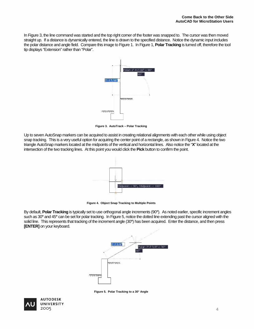
To control Object Snap Tracking settings, right-click on OTRACK in the Status bar, and then choose Settings from the context menu that appears. To toggle object snap tracking on or off, select OTRACK in the Status bar or press [F11] on your keyboard. Press and hold [F11] to temporarily toggle Object Snap Tracking. You can only turn on or off Object Snap Tracking. It must be turned on and at least one object snap must be activated in order to use Object Snap Tracking.
Figure 6. Object Snap Tracking Settings
To control Polar Tracking settings, right-click on POLAR in the Status bar, and then choose Settings from the context menu that appears. To toggle polar tracking on or off, select POLAR in the Status bar or press [F10] on your keyboard. Press and hold [F10] to temporarily toggle Polar Tracking. Settings include increment angle, absolute or relative measurement, object snap tracking orthogonally or all polar angles.
Figure 7. Polar Tracking Settings
Come Back to the Other Side AutoCAD for MicroStation Users
6
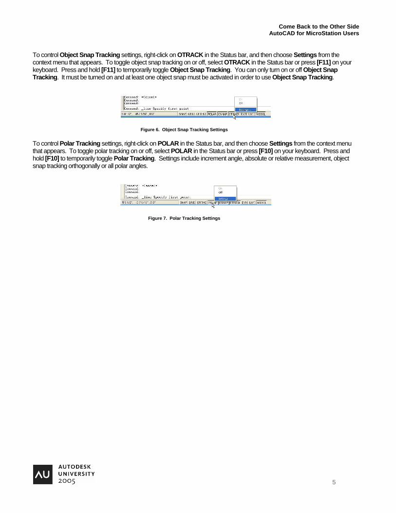
Layers versus Levels AutoCAD layers are designed to organize objects into logical groups. By grouping objects into layers, you can easily control their display status and make property changes quickly and efficiently. For example, you may place text on an Annotation layer, dimensions on a Dimension layer, walls on a Wall layer, etc. Many CAD standards incorporate standard layer names such as A-ANNO-TEXT, A-ANNO-DIMS, and A-WALL-PRHT for the previously mentioned layers. Each layer typically incorporates a standard color, linetype, and lineweight for standardization. MicroStation levels are one of the most similar features between AutoCAD and MicroStation V8. Levels changed significantly in MicroStation V8. MicroStation V7 levels were limited to 63 “numbers” and did not incorporate color, linestyle, and line weight. You can have an unlimited number of levels in MicroStation V8, and can incorporate level attributes (ByLevel, which is similar to ByLayer in AutoCAD). MicroStation V8 uses names and numbers to identify levels. AutoCAD uses names to identify layers. Although layers and levels are similar, the tools used to display and manage them are slightly different. For example, MicroStation includes the Level Display and Level Manager dialog boxes. Level Display is primarily used to toggle the display of levels on and off. Level Manager is used to manage level properties (known as attributes). In AutoCAD, the Layer Properties Manager dialog box is used to display and manage layers.
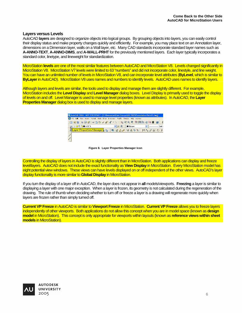
Figure 8. Layer Properties Manager Icon Controlling the display of layers in AutoCAD is slightly different than in MicroStation. Both applications can display and freeze level/layers. AutoCAD does not include the exact functionality as View Display in MicroStation. Every MicroStation model has eight potential view windows. These views can have levels displayed on or off independent of the other views. AutoCAD’s layer display functionality is more similar to Global Display in MicroStation. If you turn the display of a layer off in AutoCAD, the layer does not appear in all models/viewports. Freezing a layer is similar to displaying a layer with one major exception. When a layer is frozen, its geometry is not calculated during the regeneration of the drawing. The rule of thumb when deciding whether to turn off or freeze a layer is a drawing will regenerate more quickly when layers are frozen rather than simply turned off. Current VP Freeze in AutoCAD is similar to Viewport Freeze in MicroStation. Current VP Freeze allows you to freeze layers independently of other viewports. Both applications do not allow this concept when you are in model space (known as design model in MicroStation). This concept is only appropriate for viewports within layouts (known as reference views within sheet models in MicroStation).

Come Back to the Other Side AutoCAD for MicroStation Users
7
Both applications have other means of controlling common layer and level functions, but the dialog boxes previously mentioned are primarily used for the display function. In AutoCAD, the Layers toolbar contains controls for layers such as display, freeze, VP freeze, lock, color (view only), and layer name. In MicroStation, the equivalent is the Active Level combo box in the Attributes toolbar.
Layer Properties Manager Layer Previous Turn a Layer On or Off Make Object’s Layer Current Freeze or Thaw in ALL Viewports Layer Control Freeze or Thaw in Current Viewport Current Layer
Lock or Unlock a Layer Color of Layer
Figure 9. Layers Toolbar
Come Back to the Other Side AutoCAD for MicroStation Users
8
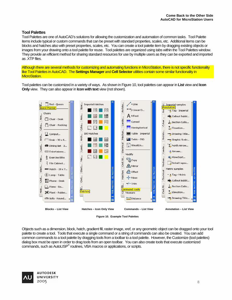
Tool Palettes Tool Palettes are one of AutoCAD’s solutions for allowing the customization and automation of common tasks. Tool Palette items include typical or custom commands that can be preset with standard properties, scales, etc. Additional items can be blocks and hatches also with preset properties, scales, etc. You can create a tool palette item by dragging existing objects or images from your drawing onto a tool palette for reuse. Tool palettes are organized using tabs within the Tool Palettes window. They provide an efficient method for sharing standard resources for use by multiple users as they can be exported and imported as .XTP files. Although there are several methods for customizing and automating functions in MicroStation, there is not specific functionality like Tool Palettes in AutoCAD. The Settings Manager and Cell Selector utilities contain some similar functionality in MicroStation. Tool palettes can be customized in a variety of ways. As shown in Figure 10, tool palettes can appear in List view and Icon Only view. They can also appear in Icon with text view (not shown).
Blocks – List View Hatches – Icon Only View Commands – List View Annotation – List View
Figure 10. Example Tool Palettes Objects such as a dimension, block, hatch, gradient fill, raster image, xref, or any geometric object can be dragged onto your tool palette to create a tool. Tools that execute a single command or a string of commands can also be created. You can add common commands to a tool palette by dragging tools from a toolbar to a tool palette. However, the Customize (tool palettes) dialog box must be open in order to drag tools from an open toolbar. You can also create tools that execute customized commands, such as AutoLISP® routines, VBA macros or applications, or scripts.

Come Back to the Other Side AutoCAD for MicroStation Users
9
Dynamic Blocks Dynamic Blocks allow you to create one block that can be customized to meet various needs. You can edit a dynamic block after insertion without the need to redefine or explode it. For example, you can create one door block that can be resized, rotated, and flipped for different specifications. You can either create new dynamic blocks or make existing block references dynamic by adding parameters and actions to specific parts of the block. These are parts that would need modifying upon insertion into a drawing. For a block to be dynamic, at least one parameter and an associated action is added to it. An action is then associated with the parameter. These parameters and actions define how the block can be modified when used in a drawing. MicroStation has long contained Dimension Driven Design to be used for cells. However, in my opinion, the editing capability is not nearly as intuitive as dynamic blocks are in AutoCAD. Parameters define positions, distances, and angles for geometry within the block. Parameters can also define restrictions or limits on the geometry. For example, suppose you are constructing a door block. You could restrict the door opening with limits of 24” – 36”. When creating a dynamic block, parameters should be defined first. Parameters that can be assigned include Point, Linear, Polar, XY, Rotation, Flip, Alignment, Visibility, Lookup, and Base. Actions define specific functions for an associated parameter. Most parameters require an associated action. Actions that can be associated to parameters include Move, Scale, Stretch, Polar Stretch, Rotate, Flip, Array, and Lookup. For example, in order to modify a door size, a stretch action would need to be associated to its linear (distance) parameter. Multiple actions can be assigned to one parameter. For example, if you had an arc representing the door swing, you would want it to resize along with the door size. In this case, you would assign a scale action to the linear (distance) parameter as well. When a dynamic block is selected in the drawing, its actions appear in the form of special grips. Click on these actions to view potential modifications. In Figure 11, the image on the left demonstrates the Lookup action selected as it displays the custom values of the door rotation. In addition to the lookup action, there is also an alignment action , two stretch actions , and two flip actions .
Appearance as Selected in Drawing Appearance in Block Editor
Figure 11. Dynamic Block – Architectural Door The alignment action allows you to keep the block parallel to an object line at the specified point. For example, you could position your cursor on one side of a wall line or another and the block will automatically align to the closest wall line. The stretch action allows you to resize the linear parameters. For example, you could resize the door size or the wall size in Figure 11. Flip actions allow you to mirror the associated geometry. For example, you could mirror the door left to right or top to bottom to represent multiple positions in a drawing.
Come Back to the Other Side AutoCAD for MicroStation Users
10
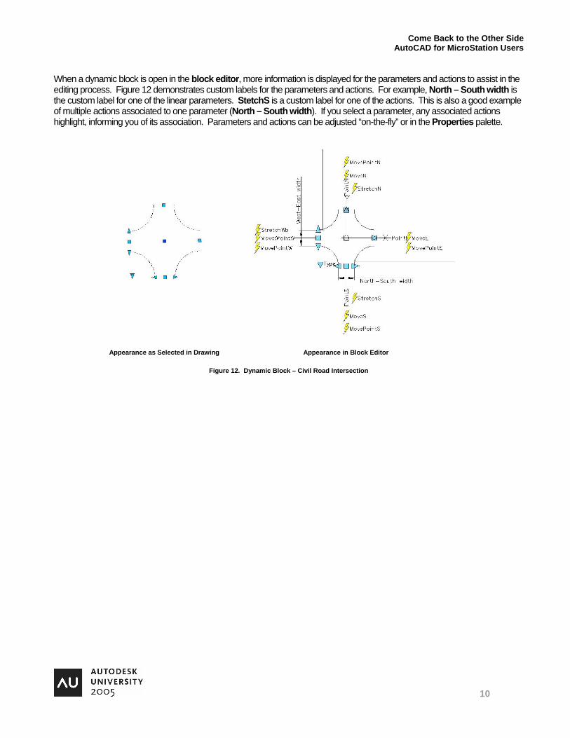
When a dynamic block is open in the block editor, more information is displayed for the parameters and actions to assist in the editing process. Figure 12 demonstrates custom labels for the parameters and actions. For example, North – South width is the custom label for one of the linear parameters. StetchS is a custom label for one of the actions. This is also a good example of multiple actions associated to one parameter (North – South width). If you select a parameter, any associated actions highlight, informing you of its association. Parameters and actions can be adjusted “on-the-fly” or in the Properties palette.
Appearance as Selected in Drawing Appearance in Block Editor
Figure 12. Dynamic Block – Civil Road Intersection
Come Back to the Other Side AutoCAD for MicroStation Users
11
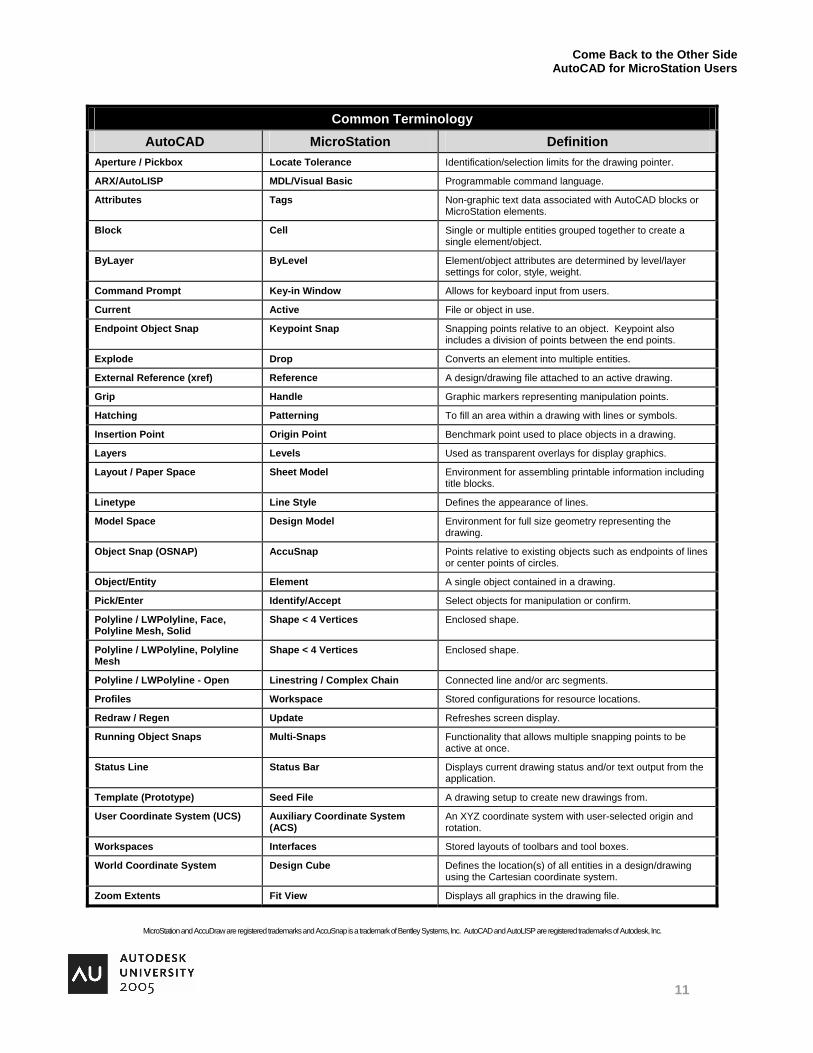
Common Terminology AutoCAD MicroStation Definition
Aperture / Pickbox Locate Tolerance Identification/selection limits for the drawing pointer.
ARX/AutoLISP MDL/Visual Basic Programmable command language.
Attributes Tags Non-graphic text data associated with AutoCAD blocks or MicroStation elements.
Block Cell Single or multiple entities grouped together to create a single element/object.
ByLayer ByLevel Element/object attributes are determined by level/layer settings for color, style, weight.
Command Prompt Key-in Window Allows for keyboard input from users.
Current Active File or object in use.
Endpoint Object Snap Keypoint Snap Snapping points relative to an object. Keypoint also includes a division of points between the end points.
Explode Drop Converts an element into multiple entities.
External Reference (xref) Reference A design/drawing file attached to an active drawing.
Grip Handle Graphic markers representing manipulation points.
Hatching Patterning To fill an area within a drawing with lines or symbols.
Insertion Point Origin Point Benchmark point used to place objects in a drawing.
Layers Levels Used as transparent overlays for display graphics.
Layout / Paper Space Sheet Model Environment for assembling printable information including title blocks.
Linetype Line Style Defines the appearance of lines.
Model Space Design Model Environment for full size geometry representing the drawing.
Object Snap (OSNAP) AccuSnap Points relative to existing objects such as endpoints of lines or center points of circles.
Object/Entity Element A single object contained in a drawing.
Pick/Enter Identify/Accept Select objects for manipulation or confirm.
Polyline / LWPolyline, Face, Polyline Mesh, Solid
Shape < 4 Vertices Enclosed shape.
Polyline / LWPolyline, Polyline Mesh
Shape < 4 Vertices Enclosed shape.
Polyline / LWPolyline - Open Linestring / Complex Chain Connected line and/or arc segments.
Profiles Workspace Stored configurations for resource locations.
Redraw / Regen Update Refreshes screen display.
Running Object Snaps Multi-Snaps Functionality that allows multiple snapping points to be active at once.
Status Line Status Bar Displays current drawing status and/or text output from the application.
Template (Prototype) Seed File A drawing setup to create new drawings from.
User Coordinate System (UCS) Auxiliary Coordinate System (ACS)
An XYZ coordinate system with user-selected origin and rotation.
Workspaces Interfaces Stored layouts of toolbars and tool boxes.
World Coordinate System Design Cube Defines the location(s) of all entities in a design/drawing using the Cartesian coordinate system.
Zoom Extents Fit View Displays all graphics in the drawing file.
MicroStation and AccuDraw are registered trademarks and AccuSnap is a trademark of Bentley Systems, Inc. AutoCAD and AutoLISP are registered trademarks of Autodesk, Inc.