AutoCAD - Digital Riverdrh2.img.digitalriver.com/.../pdf/Learning_AutoCAD_Mechanical_2010 … ·...
24
Autodesk Official Training Guide Essentials AutoCAD ® Mechanical 2010 Learning AutoCAD ® Mechanical 2010, Volume 1 New users will use hands-on exercises to efficiently create 2D mechanical designs and engineering production drawings. 206B1-050000-CM00A May 2009
Transcript of AutoCAD - Digital Riverdrh2.img.digitalriver.com/.../pdf/Learning_AutoCAD_Mechanical_2010 … ·...

Autodesk Official Training Guide
Essentials
AutoCAD®
Mechanical 2010
Learning AutoCAD® Mechanical 2010, Volume 1 New users will use hands-on exercises to efficiently create 2D mechanical designs and engineering production drawings.
206B1-050000-CM00A May 2009

© 2009 Autodesk, Inc. All rights reserved. Except as otherwise permitted by Autodesk, Inc., this publication, or parts thereof, may not be reproduced in any form, by any method, for any purpose. Certain materials included in this publication are reprinted with the permission of the copyright holder.
Trademarks The following are registered trademarks or trademarks of Autodesk, Inc., in the USA and other countries: 3DEC (design/ logo), 3December, 3December.com, 3ds Max, ADI, Alias, Alias (swirl design/logo), AliasStudio, Alias|Wavefront (design/ logo), ATC, AUGI, AutoCAD, AutoCAD Learning Assistance, AutoCAD LT, AutoCAD Simulator, AutoCAD S Q L E x t e n s i o n , AutoCAD SQL Interface, Autodesk, Autodesk Envision, Autodesk Insight, Autodesk Intent, Autodesk Inventor, Autodesk Map, Autodesk MapGuide, Autodesk Streamline, AutoLISP, AutoSnap, AutoSketch, AutoTrack, Backdraft, Built with ObjectARX (logo), Burn, Buzzsaw, CAiCE, Can You Imagine, Character Studio, Cinestream, Civil 3D, Cleaner, Cleaner Central, ClearScale, Colour Warper, Combustion, Communication Specification, Constructware, Content Explorer, Create>what’s>Next> (design/logo), Dancing Baby (image), DesignCenter, Design Doctor, Designer’s Toolkit, DesignKids, DesignProf, DesignServer, DesignStudio, Design|Studio (design/logo), Design Web Format, Discreet, DWF, DWG, DWG (logo), DWG Extreme, DWG TrueConvert, DWG TrueView, DXF, Ecotect, Exposure, Extending the Design Team, Face Robot, FBX, Filmbox, Fire, Flame, Flint, FMDesktop, Freewheel, Frost, GDX Driver, Gmax, Green Building Studio, Heads‐up Design, Heidi, HumanIK, IDEA Server, i‐drop, ImageModeler, iMOUT, Incinerator, Inferno, Inventor, Inventor LT, Kaydara, Kaydara (design/logo), Kynapse, Kynogon, LandXplorer, LocationLogic, Lustre, Matchmover, Maya, Mechanical Desktop, Moonbox, MotionBuilder, Movimento, Mudbox, NavisWorks, ObjectARX, ObjectDBX, Open Reality, Opticore, Opticore Opus, PolarSnap, PortfolioWall, Powered with Autodesk Technology, Productstream, ProjectPoint, ProMaterials, RasterDWG, Reactor, RealDWG, Real‐time Roto, REALVIZ, Recognize, Render Queue, Retimer, Reveal, Revit, Showcase, ShowMotion, SketchBook, Smoke, Softimage, Softimage|XSI (design/logo), SteeringWheels, Stitcher, Stone, StudioTools, Topobase, Toxik, TrustedDWG, ViewCube, Visual, Visual Construction, Visual Drainage, Visual Landscape, Visual Survey, Visual Toolbox, Visual LISP, Voice Reality, Volo, Vtour, Wire, Wiretap, WiretapCentral, XSI, and XSI (design/logo).
The following are registered trademarks or trademarks of Autodesk Canada Co. in the USA and/or Canada and other countries: Backburner, Multi‐Master Editing, River, and Sparks.
The following are registered trademarks or trademarks of Moldflow Corp. in the USA and/or other countries: Moldflow MPA, MPA (design/logo), Moldflow Plastics Advisers, MPI, MPI (design/logo), Moldflow Plastics Insight, MPX, MPX (design/ logo), Moldflow Plastics Xpert. All other brand names, product names, or trademarks belong to their respective holders.
Disclaimer
THIS PUBLICATION AND THE INFORMATION CONTAINED HEREIN IS MADE AVAILABLE BY AUTODESK, INC. “AS IS.” AUTODESK, INC. DISCLAIMS ALL WARRANTIES, EITHER EXPRESS OR IMPLIED, INCLUDING BUT NOT LIMITED TO ANY IMPLIED WARRANTIES OF MERCHANTABILITY OR FITNESS FOR A PARTICULAR PURPOSE REGARDING THESE MATERIALS.
Published by: Autodesk, Inc. 111 Mclnnis Parkway San Rafael, CA 94903, USA

iii
Contents
Introduction ................................................................................................ xi
Chapter 1: Getting Started ........................................................................... 1 Lesson: Interacting with the User Interface ........................................................ 2
The User Interface .................................................................................... 3 Exploring the Ribbon ................................................................................ 6 Accessing Help Information ...................................................................... 9 About the Configuration and Setup Guide .............................................. 11 Exercise: Interact with the User Interface ............................................... 14
Lesson: Common Drawing Setup ...................................................................... 17 About Drawing Templates ....................................................................... 18 About Standards‐Based Design ............................................................... 19 Creating a New Drawing Based on a Template ....................................... 21 Creating a New Template ........................................................................ 22 Changing the Location of Templates ....................................................... 24 Exercise: Create and Use Template Drawings ......................................... 26
Chapter Summary ............................................................................................. 29
Chapter 2: Object Property and Layer Management .................................. 31 Lesson: Property Management ......................................................................... 32
About Automatic Management of Layers and Object Properties ............ 33 Managing Layers Using the Mechanical Layer Manager ......................... 35 How to Configure Object Property Settings in a Standard ...................... 39 Exercise: Automatic Property Management ........................................... 43
Lesson: Layer Control ........................................................................................ 47 Changing the Current Layer .................................................................... 48 Layer Functions ....................................................................................... 51 Layer Display ........................................................................................... 53 Exercise: Control Layer Display and Geometry on Layers ........................ 57
Chapter Summary ............................................................................................. 59
Chapter 3: Organizing Drawing Geometry ................................................... 61 Lesson: Drawing Creation Workflows and Organization .................................... 62
About the Organization Methods ........................................................... 63 About Mechanical Structure ................................................................... 65

iv Contents ■
Lesson: Structuring Data in Drawings ........................................................... 68 How to Create a Structured Design .................................................... 69 Creating Components and Component Views .................................... 71 Creating Folders Within a Component View ....................................... 77 Restructuring Components ................................................................. 78 Settings that Control Structure Creation ............................................. 81 Exercise: Create a Drawing Using Structure ........................................ 85
Lesson: Reusing and Editing Structured Data ................................................ 90 About Structure Definitions, Instances, and Occurrences ................... 91 Reusing Structured Data from the Browser ........................................ 94 Reusing Structured Data From the Structure Catalog ......................... 98 Edit a Structure Definition ................................................................ 106 Changing the Display of Instances .................................................... 112 Exercise: Reuse and Edit Structured Data ......................................... 115
Chapter Summary ....................................................................................... 120
Chapter 4: Tools for Creating Key Geometry .......................................... 121 Lesson: Core Design Tools ........................................................................... 124
Creating Rectangles ........................................................................... 125 Placing Hatch .................................................................................... 127 Adding Fillets ..................................................................................... 131 Adding Chamfers ............................................................................... 134 Creating Contours ............................................................................. 138 Exercise: Create Geometry Using the Core Design Tools ................... 143
Lesson: Power Snaps ................................................................................... 146 About Power Snaps ........................................................................... 147 Configuring Power Snaps .................................................................. 148 Activating Power Snap Configurations .............................................. 152 Exercise: Configure and Activate Power Snaps ................................. 154
Lesson: Centerlines ..................................................................................... 158 About Mechanical Centerlines .......................................................... 159 Creating Centerlines .......................................................................... 160 Centerline Settings ............................................................................ 171 Exercise: Add Centerlines and Holes ................................................. 173
Lesson: Construction Lines .......................................................................... 177 About Construction Lines .................................................................. 178 Drawing Construction Lines .............................................................. 179 Placing Construction Lines Automatically ......................................... 181 Inserting and Using Projection Crosshairs ......................................... 183 Erasing Construction Lines ................................................................ 185 Exercise: Create and Use Construction Lines .................................... 188
Lesson: Designing with Lines ...................................................................... 192 Creating Section Lines ....................................................................... 193 Creating Zigzag Lines ......................................................................... 196 Creating Breakout Lines .................................................................... 197 Creating Symmetrical Lines ............................................................... 198 Exercise: Draw with Different Line Tools ........................................... 200

vContents ■
Lesson: Adding Standard Feature Data for Holes and Slots ........................ 202 About Standard Content ................................................................... 203 About Standard Features .................................................................. 205 Inserting Standard Holes ................................................................... 208 Inserting Threaded Features ............................................................. 213 Inserting Slot Features ...................................................................... 215 Exercise: Add Holes and Slots ........................................................... 219
Chapter Summary ....................................................................................... 223
Chapter 5: Tools for Manipulating Geometry ........................................ 225
Lesson: Editing Tools ................................................................................... 226 Copying Objects ................................................................................ 227 Offsetting Objects ............................................................................. 228 Joining Entities .................................................................................. 229 Breaking Objects into Multiple Parts ................................................ 231 Scaling Objects Along the X and Y Axes ............................................ 234 Exercise: Basic Editing Tools .............................................................. 236
Lesson: Power Commands .......................................................................... 238 About Power Commands .................................................................. 239 Modifying Objects ............................................................................. 239 Deleting Objects ................................................................................ 240 Copying Objects ................................................................................ 241 Recalling Commands ......................................................................... 242 Creating Views .................................................................................. 243 Exercise: Use Power Commands ....................................................... 245
Lesson: Associative Hide ............................................................................. 248 About Associative Hides .................................................................... 249 Creating an Associative Hide ............................................................. 251 Editing an Associative Hide ............................................................... 257 Exercise: Create and Edit Associative Hides ...................................... 259 Exercise: Create and Edit Associative Hides ‐ When Using
Structure .................................................................................... 264 Chapter Summary ....................................................................................... 268
Chapter 6: Mechanical Part Generators ................................................. 269
Lesson: Standard Parts ................................................................................ 274 About Standard Parts ........................................................................ 275 Inserting Standard Parts Using the Parts Library ............................... 279 Standard Part Library Favorites ......................................................... 282 Inserting Standard Parts Using the Ribbon and Menus ..................... 286 Inserting Screw Components ............................................................ 289 Creating and Using Screw Templates ................................................ 294 Changing Part Representations ......................................................... 296 Adding Leader Notes to Standard Parts ............................................ 297 Exercise: Insert and Notate Standard Parts ....................................... 301 Exercise: Insert from the Content Libraries Palette ........................... 306

vi Contents ■
Lesson: Chains and Belts ............................................................................. 317 Creating Sprockets and Pulleys ......................................................... 318 Calculate Chain and Belt Lengths ...................................................... 319 Inserting Chains and Belts ................................................................ 322 Exercise: Design Chains and Belts ..................................................... 324
Lesson: Shaft Generator .............................................................................. 328 Generating Shafts .............................................................................. 329 Creating Basic Shaft Sections ............................................................ 332 Placing Shaft Contour Features ......................................................... 334 Creating Complex Shaft Segments .................................................... 336 Inserting Shaft Display Features ........................................................ 341 Creating Associative Shaft Views ...................................................... 344 Exercise: Place a Shaft in an Assembly ............................................. 346
Lesson: Standard Shaft Parts ....................................................................... 350 Inserting from the Shaft Generator .................................................. 351 Inserting from Other Locations ......................................................... 353 Exercise: Insert Standard Shaft Parts ................................................ 357
Lesson: Springs ............................................................................................ 360 Process of Adding Springs to Your Assembly Design ......................... 361 Inserting Springs from a Standard .................................................... 365 Inserting Modified Designed Springs ................................................ 368 Inserting Springs By Only Drawing the Geometry ............................. 372 Exercise: Insert a Spring .................................................................... 374
Chapter Summary ....................................................................................... 377
Chapter 7: Creating Drawing Sheets ..................................................... 379 Lesson: Model Space Views in Layouts ....................................................... 380
Creating Model Views in Layouts ...................................................... 381 Creating Detail Views in a Layout ..................................................... 385 Creating Scale Areas in Model Space ................................................ 388 Creating Viewports from Scale Areas ................................................ 390 Zooming All Viewport to Defined Scales ........................................... 391 Viewport Layer On/Off ...................................................................... 392 Exercise: Create Viewports and Details in Layouts ............................ 393
Lesson: Creating Drawing Sheets in Model Space ....................................... 399 Process of Plotting from Model Space .............................................. 400 Determining Scale Overrides ............................................................. 401 Creating Detail Views in Model Space .............................................. 402 Exercise: Create Drawing Sheets in Model Space ............................. 404
Lesson: Annotation Views When Using Structure ....................................... 407 About Annotation Views ................................................................... 408 Creating Annotation Views ............................................................... 410 Editing Annotation Views .................................................................. 415 Exercise: Create and Edit Annotation Views ..................................... 418

viiContents ■
Lesson: Title Blocks and Drawing Borders ................................................... 425 Inserting Drawing Title Blocks and Borders ...................................... 426 Replacing Inserted Title Blocks or Borders ........................................ 430 Editing Title Block Attribute Values ................................................... 432 Drawing Sheet Settings ..................................................................... 433 Title Block Layer On/Off .................................................................... 434 Exercise: Insert Title Blocks and Borders .......................................... 435
Chapter Summary ....................................................................................... 437

iii
Contents
Chapter 8: Dimensioning and Annotating Your Drawings ........................... 1 Lesson: Annotation and Annotation Symbols ................................................... 4
Insert Text ............................................................................................... 5 Inserting Surface Textures ....................................................................... 6 Inserting Weld Symbols ............................................................................ 9 Inserting Feature Control Frames ........................................................... 12 Inserting Edge Symbols ........................................................................... 15 Symbol Libraries ...................................................................................... 17 Inserting Weld Representations .............................................................. 22 Inserting Datum Identifiers ..................................................................... 24 Inserting Feature Identifiers .................................................................... 26 Inserting Datum Targets .......................................................................... 28 Inserting Taper and Slope Symbols ......................................................... 31 Standards Symbol Settings ...................................................................... 33 Exercise: Annotate Parts and Subassemblies .......................................... 35
Lesson: Creating Dimensions ............................................................................ 41 Placing Power Dimensions ...................................................................... 42 Power Dimensioning Options and Settings ............................................. 49 Chamfer Dimensions ............................................................................... 55 Overdrawn Dimensions ........................................................................... 56 Placing Multiple Dimensions ................................................................... 58 Control Dimension Standards ................................................................. 62 Exercise: Use the Power Dimension Command ...................................... 64 Exercise: Add Different Power Dimensions ............................................. 68 Exercise: Place Multiple Dimensions Automatically ................................ 72
Lesson: Editing Dimensions ............................................................................... 74 Modifying Dimensions with Power Edit .................................................. 75 Editing Multiple Dimensions ................................................................... 76 Stretching Objects with Dimensions ....................................................... 77 Arranging Dimensions ............................................................................. 79 Aligning Dimensions ................................................................................ 80 Joining Dimensions ................................................................................. 81 Splitting Dimensions ................................................................................ 82 Breaking Dimension Lines ....................................................................... 83 Checking Dimensions .............................................................................. 84 Exercise: Edit Dimensions ....................................................................... 86

iv Contents ■
Lesson: Hole Charts and Fits Lists ................................................................. 91 Creating Hole Charts ........................................................................... 92 Hole Chart Settings ............................................................................. 96 Placing a Fits List ................................................................................. 98 Exercise: Add Hole Charts and Fits Lists ............................................ 100
Lesson: Revision Lists .................................................................................. 104 Inserting Revision Lines in Drawings ................................................. 105 Inserting Automatic Revision List ...................................................... 106 Updating Revision List ....................................................................... 109 Exercise: Create a Revision List ......................................................... 110
Chapter Summary ....................................................................................... 113
Chapter 9: Bill of Materials, Parts Lists, and Balloons ........................... 115 Lesson: Part References .............................................................................. 118
About Part References ...................................................................... 119 Adding Part References ..................................................................... 120 Editing Part References ..................................................................... 123 Exercise: Create Part References ....................................................... 126
Lesson: Bill of Materials .............................................................................. 129 Creating Bill of Materials .................................................................. 130 Structured Components and the BOM ............................................. 132 Expanding Subassembly Information ................................................ 136 Sorting BOM Data ............................................................................. 137 Renumbering BOM Entries ............................................................... 138 Bill of Material Standards ................................................................. 140 Exercise: Create and Edit a Bill of Materials ...................................... 141 Exercise: Create and Edit a Bill of Materials ‐ When Using
Structure .................................................................................... 144
Lesson: Inserting Parts Lists ........................................................................ 148 Inserting a Parts List ......................................................................... 149 Editing a Parts List ............................................................................ 150 Parts List Standards ........................................................................... 152 Exercise: Insert and Edit Parts Lists ................................................... 154 Exercise: Insert and Edit Parts Lists When Using Structure ............... 158
Lesson: Ballooning Parts ............................................................................. 160 Adding Balloons ................................................................................ 161 Editing Balloons ................................................................................. 164 Balloon Standards ............................................................................. 166 Exercise: Add Balloons to Assembly Drawings .................................. 169
Chapter Summary ....................................................................................... 175
vContents ■
Chapter 10: Design Calculations ........................................................... 177 Lesson: Design Calculations ........................................................................ 178
About the Calculation Tools .............................................................. 179 Calculating Moment of Inertia .......................................................... 180 Calculating Moment of Inertia with Predefined Profiles ................... 183 Calculating Deflection Line ................................................................ 184
Calculating Shaft Stresses ................................................................. 187 Calculating the Finite Element Analysis ............................................ 190 Exercise: Calculate Moments of Inertia ............................................ 196 Exercise: Calculate the Deflection Line ............................................. 198 Exercise: Calculate Shaft Strength ..................................................... 202 Exercise: Calculate FEA Stresses ........................................................ 205
Chapter Summary ....................................................................................... 209
Chapter 11: Leveraging Your Exisitng Data ............................................ 211 Lesson: DWG Files ....................................................................................... 212
Mechanical Drawing Files in AutoCAD .............................................. 213 Removing Mechanical Objects and Structure from the DWG File..... 214 Exercise: Remove Mechanical Content from a Drawing .................... 217
Lesson: IGES Files ........................................................................................ 220 IGES In ............................................................................................... 221 IGES Out ............................................................................................ 222 Exercise: IGES In and Out .................................................................. 224
Lesson: Inventor Link .................................................................................. 226 About Inventor Link .......................................................................... 227 Using Inventor Link ........................................................................... 229 How to Create Drawing Views of Linked Models .............................. 230 Exercise: Link and Create Views of an Inventor File .......................... 235
Chapter Summary ....................................................................................... 240
Chapter 12: Mechanical Options for the CAD Manager ......................... 241 Lesson: Standards‐Based Design ................................................................. 242
Introduction to Standards‐Based Design ........................................... 243 Selecting a Standard and Creating a Custom Standard ..................... 245 Setting the Model Scale .................................................................... 247 Setting a Default Standards Template ............................................... 249 Exercise: Create and Set a Default Standard Template ...................... 251
Lesson: Configure Layer, Text, and Object Properties ................................. 253 Configuring Layers ............................................................................. 254 About Standard Elements and Accessing Their Settings ................... 257 Configuring Standard Properties ....................................................... 259 Exercise: Configure Layers and Object Properties ............................. 265

vi Contents ■
Lesson: Configure the Annotation Tools ..................................................... 271 About Dimensions and Annotation ................................................... 272 Configuring Dimension Styles ........................................................... 273 Configuring Hole Charts .................................................................... 282 Configuring Drawing Sheets .............................................................. 286 Configuring Notes ............................................................................. 289 Other Annotation Symbols and Their Settings .................................. 293 Exercise: Set Annotation Properties .................................................. 302
Lesson: Configure Component Properties, BOMs, Parts Lists, and Balloons ................................................................................ 305
About BOM Data ............................................................................... 306 Configuring BOM Settings for BOM Related Items ............................ 307 Available Component Properties ...................................................... 311 Configuring Component Properties .................................................. 315 Configuring the BOM ........................................................................ 317 Configuring the Parts List .................................................................. 320 Configuring the Balloons ................................................................... 324 Exercise: Configure Properties, BOM, Parts List, and
Balloons .............................................................................. 328 Chapter Summary ........................................................................................ 333
Appendix .............................................................................................. 335

viii ■ Contents

ixAcknowledgements ■
Acknowledgements
The Autodesk Learning team wishes to thank everyone who participated in the development of this project, with special acknowledgement to the authoring contributions and subject matter expertise of Ron Myers and CrWare, LP.
CrWare, LP began publishing courseware for Autodesk® Inventor® in 2001. Since that time, the company has grown to include full‐time curriculum developers, subject matter experts, technical writers, and graphics specialists, each with a unique set of industry experiences and talents that enables CrWare to create content that is both accurate and relevant to meeting the learning needs of its readers and customers.
The company's Founder and General Partner, Ron Myers, has been using Autodesk® products since 1989. During that time, Ron Myers worked in all disciplines of drafting and design, until 1996 when he began a career as an Applications Engineer, Instructor, and Author. Ron Myers has been creating courseware and other training material for Autodesk since 1996 and has written and created training material for AutoCAD®, Autodesk Inventor, AutoCAD® Mechanical, Mechanical Desktop®, and Autodesk® Impression.

x ■ Acknowledgements

xi
Introduction
Welcome to the Learning AutoCAD Mechanical 2010 training guide for use in Authorized Training Center (ATC®) locations, corporate training settings, and other classroom settings.
Although this guide is designed for instructor‐led courses, you can also use it for self‐paced learning. The guide encourages self‐learning through the use of the AutoCAD® Mechanical 2010 Help system. This introduction covers the following topics: ■ Course objectives ■ Prerequisites ■ Using this guide ■ CD contents ■ Completing the exercises ■ Installing the exercise data files from the CD ■ Notes, tips, and warnings ■ Feedback This guide is complementary to the software documentation. For detailed explanations of features and functionality, refer to the Help in the software.
Course Objectives After completing this guide, you will be able to: ■ Identify the main interface elements, their setup, and what Help information is available. Create
and use drawing template files. ■ Describe the object property management system, where layers are configured, and the tools for
manipulating layers. ■ Describe the workflows for organizing drawing geometry and create Mechanical structure in a
drawing by creating components, component views, and folders. ■ Describe the core mechanical design tools of rectangle, hatch, fillet, chamfer, holes, slots, and
threads and how to use them to create and modify geometry in your drawings. ■ Modify and edit drawing objects by creating multiple offset copies, by scaling them with separate
values for the X and Y direction, or by using a power command. ■ Insert industry standard parts into your assembly designs. ■ Create production‐ready drawings in model space and layouts of structured and non‐structured
geometry and insert title blocks and borders. ■ Notate a drawing through the creation and editing of dimensions, hole charts, fits lists, and
mechanical symbols. ■ Explain how to create and edit a bill of materials, parts list, and balloons. ■ Describe the tools that you can use to verify whether or not the standard parts or custom parts
within your design meet or exceed the requirements for operational use.

xiv Introduction ■
■ Exchange data between CAD systems in the form of Mechanical DWG and IGES files and create Mechanical drawings using Inventor Link.
■ Create a custom drafting standard and drawing template that includes the configuration settings for layers, object properties, symbols, text, BOM, parts list, balloons, and other annotation tools.
Prerequisites This guide is designed for users new to AutoCAD Mechanical 2010. ■ A basic understanding of mechanical drafting or design. ■ A working knowledge of AutoCAD®. ■ A working knowledge of Microsoft® Windows® XP, or Microsoft® Windows® Vista.
Using This Guide The lessons are independent of each other. However, it is recommended that you complete these lessons in the order that they are presented unless you are familiar with the concepts and functionality described in those lessons. Each chapter contains: ■ Lessons
Usually two or more lessons in each chapter. ■ Exercises
Practical, real‐world examples for you to practice using the functionality you have just learned. Each exercise contains step‐by‐step procedures and graphics to help you complete the exercise successfully.
CD Contents
The CD attached to the back cover of this book contains all the data and drawings you need to complete the exercises in this guide.
Completing the Exercises You can complete the exercise in two ways: using the book or on screen. ■ Using the book
Follow the step‐by‐step exercises in the book. ■ On screen
Click the Learning AutoCAD Mechanical 2010 icon on your desktop, installed from the CD, and follow the step‐by‐step exercises on screen. The onscreen exercises are the same as those in the book. The onscreen version has the advantage that you can concentrate on the screen without having to glance down at your book.
xiiiIntroduction ■
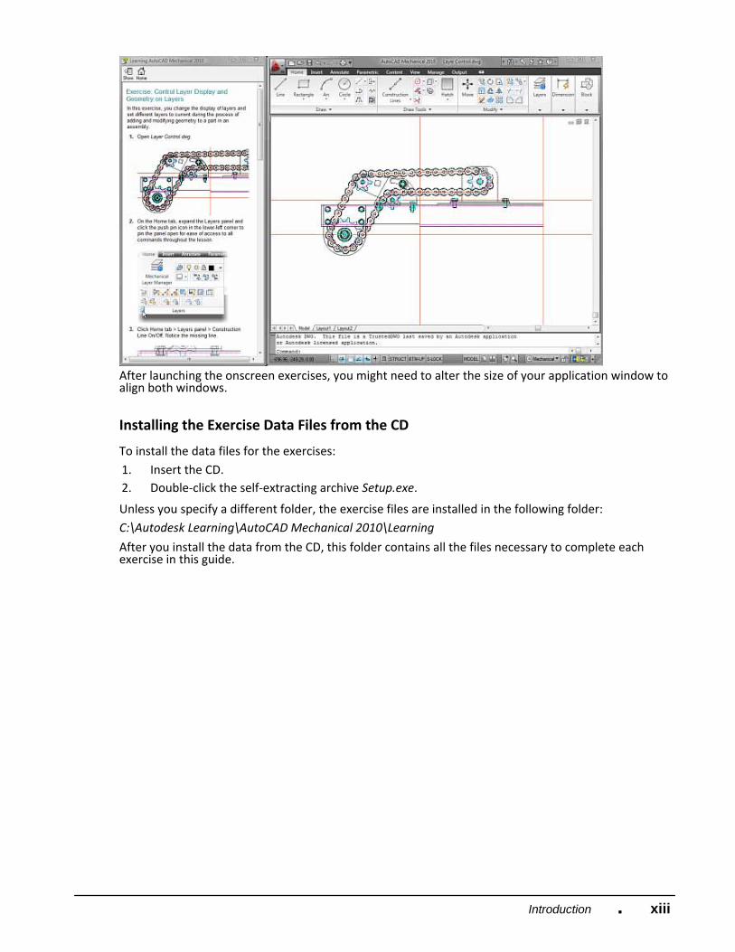
After launching the onscreen exercises, you might need to alter the size of your application window to align both windows.
Installing the Exercise Data Files from the CD
To install the data files for the exercises: 1. Insert the CD. 2. Double‐click the self‐extracting archive Setup.exe.
Unless you specify a different folder, the exercise files are installed in the following folder: C:\Autodesk Learning\AutoCAD Mechanical 2010\Learning
After you install the data from the CD, this folder contains all the files necessary to complete each exercise in this guide.

xiv Introduction ■
Notes, Tips, and Warnings
Throughout this guide, notes, tips, and warnings are called out for special attention. Notes contain guidelines, constraints, and other explanatory information.
Tips provide information to enhance your productivity.
Warnings provide information about actions that might result in the loss of data, system failures, or other serious consequences.
Feedback
We always welcome feedback on Autodesk Official Training Guides. After completing this course, if you have suggestions for improvements or if you want to report an error in the book or on the CD, please send your comments to [email protected].
Digital Prototyping
Most of you probably recognize the enormity of the issues facing manufacturers and engineering companies today. Manufacturing and design are changing at the speed of sound. Manufacturing is being performed globally, and can change locations at any time. Design teams are becoming "virtual", located in many geographies and companies. And customers are located all over the world, each demanding greater communication, customization, shorter timelines, and customer service.
And if you are manufacturing with sustainability in mind, you are likely wrestling with issues such as optimizing materials use and reducing waste, avoiding hazardous or restricted materials, using energy

xvIntroduction ■
efficiently in manufacturing, designing energy‐efficient products, minimizing water use, or maintaining compliance with laws and regulations. Addressing these issues can both improve a manufacturer’s environmental performance and provide a distinct competitive advantage.
It is critical that manufacturers start to leverage our assets across the organization, from sales and marketing, to purchasing, manufacturing, technical documentation, and field service. Not to mention plant engineering and maintenance and of course our customers. Throughout the years of design and manufacturing, industry has talked of a future "nirvana" where throughout the product or project development cycle all knowledge would be captured and communicated. Many of you have heard the terms "Art to Part", "Cradle to Grave" and "Concept to Obsolescence". The concept has always been simple; the practical implementation has been costly, both in time and money.
The future is here. So much so, that the industry has given it a name. Digital Prototyping. The concept remains the same. Capture data digitally at its source and pull and push it throughout the lifecycle of the product or project.
The "text book" definition of a digital prototype is a digital simulation of a product that can be used to test form, fit, and function. The digital prototype becomes more and more complete as all associated conceptual, mechanical, and electrical design data are integrated. A complete digital prototype is a true digital simulation of the entire end product, and can be used to virtually optimize and validate a product to reduce the necessity of building expensive physical prototypes.
Technology has caught up to the vision, but technology is only as effective as the implementation of the tools available. Process must be examined and determined to best meet your organization's business, and the cultural change is so huge that we could spend days if not weeks discussing how to best get the 'people' part of the equation to understand and believe that it is not only the "right" thing to do but critical to their future.
For years Autodesk® has democratized technology, allowing for attainability, scalability, and affordability. Like AutoCAD 25 years ago, Autodesk has enabled organizations of any size to practically implement the technology; processes and infrastructure required integrate digital prototyping into your development process.
Digital Prototyping is not a "one size fits all" solution. The sheer array of design projects is overwhelming. How can a consumer products company that must appeal to consumers with a cool look and feel and sell 1000s of units implement the same solution as a custom industrial equipment manufacturer that never designs or builds the same unit twice implement the same solution?
Digital Prototyping is a concept that can be adapted to any design process. The technology and process will differ, but the philosophy is the same.
In order to understand how digital prototyping can help manufacturers of all sizes and marketplaces, it is important to understand the general workflow of a design and fulfillment of a product. While each of you come from within this workflow it is easy to lose sight of the overarching process and the people involved. As we look at the workflow, you can see that many departments and steps are involved in this design project and each has its own set of challenges.
Products are typically conceptually created by studying market needs and wants. These concepts can come from many sources including sales and marketing, industrial design, or conceptual engineering. No matter where they come from, the end goal is to meet a customer's need or want.
Manufacturing is responsible to build what engineering has designed, purchasing is responsible to support those efforts and track costs. Each department has deadlines and if mistakes aren't caught until the build phase they can be costly in both time and money.
In the midst of this process, documents and data must be controlled and communicated. Depending on the type of product being created, regulations must be adhered to and changes incorporated. This

xvi Introduction ■
responsibility falls within various departments, but Document Control and/or Project Management are the most common.
Without Digital Prototyping, these “islands of competency” are just that; islands. The pipelines of communication are manual and have the ability to break down. With each hand‐off of information, knowledge is lost or misinterpreted.
Digital Prototyping ‐ Industrial Equipment Manufacturer
Design is not about a single person or company, but about the collaboration of many. This company designs, builds, and sells packaging systems for the food and beverage industry. Their customers are located in all parts of the world, and they recognize that in order to grow their position in the marketplace that they need to quickly bring new products to market and listen to their customer’s needs, and meet those expectations.

xviiIntroduction ■
This manufacturer has determined that to meet their business goals, they will transition to Digital Prototyping, or virtually building the entire machine, communicating to all departments involved as the design develops.
Before the system was manufactured or even physically prototyped, marketing and sales wanted to show customers the concept and allow those customers to give feedback and visualize various options. Those departments utilized Autodesk® Showcase® to dynamically allow customers to interact with the virtual prototype, see various options and make decisions with respect to their needed configuration.
So, how did the process work? The following shows the workflow and products used to complete the design and deliver the equipment to the customer.
In order to keep control of all engineering, design and manufacturing data, Vault Manufacturing was used to vault that data and make it accessible to all project members including mechanical, electrical, manufacturing, purchasing and sales and marketing. Vault Manufacturing allowed this organization to insure that no one was working on the same part of the design at the same time, that everyone was working on the same version of the design, and that downstream departments could view the various sub‐systems and offer input to keep cost down and allow for efficient manufacturing and assembly.
The mechanical design team utilized Autodesk® Inventor® Professional to create the various mechanical sub‐systems of the product. These sub‐systems included the frame, mechanisms, sheet metal enclosures, and mounting hardware for the electrical systems. They also agreed on standards and stuck to them including iproperties, templates, sheet metal styles, naming conventions, dimensioning styles, and hardware.
Another difference with this design is that they used Inventor Professional's capabilities to simulate various mechanisms and analyze parts for form, fit and function as well as safety considerations. As issues arose, electrical design and manufacturing could review the designs through Vault Manufacturing and Design Review to help make suggestions for improvement.
The electrical design team utilized AutoCAD® Electrical to design the electrical systems. Again, this team agreed upon standards to insure consistent device tags, wire numbers and report formats that manufacturing and purchasing could use electronically without reentering the data into their own systems. By using AutoCAD Electrical, wires and device tags weren’t duplicated; components such as

xviii Introduction ■
relay contacts weren’t over used causing manufacturing and purchasing to have to scramble during the build phase to correct those issues on the shop floor. By using AutoCAD Electrical’s database, accurate parts lists were generated, wire labels were created and imported into their label printer, and a To‐ From Wire list was sent to the electricians making their wiring job easy to understand.
One of the biggest changes in engineering was the ability to communicate design intent between the electrical and mechanical teams. While electrical engineers design the schematics and logic, it is typically up to the mechanical teams to mount and physically wire and plumb the electrical and fluid power (hydraulic and pneumatic) devices. Some of these devices could be light curtains, valves, drives, motors, actuators, etc. In the past this was typically done during the physical prototyping phase or during the build of a custom piece of equipment. Electricians would run string from point to point to produce accurate lengths of cables or wires, mechanical design would make their best guess on tube and pipe runs often causing costly changes in manufacturing and delay the testing and debug cycles before a product could ship to a customer site.
By utilizing Inventor Professional's routing capabilities and AutoCAD Electrical's export capabilities, the teams could accurately communicate the design intent, produce nail board drawings for cables, and simulate motion to insure that interferences wouldn’t occur.
Once the digital prototype was created, sales and marketing used Autodesk Showcase to work with customers in a dynamic environment that allowed the customers to virtually experience the equipment, test various options and make quick decisions which shortened the sales cycle.
Once the final configuration of the product was determined, the mechanical team could create detailed drawings in native DWG file format using DWG TruConnect. They could also export DXF files for sheet metal manufacturing, as well as create assembly instructions using Inventor’s presentation capability.
These presentations and detailed design documentation were exported to DWF files for the customer. The customer uses Design Review to view models, drawings, and animations and requires no CAD software. It is a free download and available to anyone.
The end result was that this company reduced change orders, saved costs by communicating throughout the process with accurate, accessible information, beat timelines and met customer's expectation. The company might have also made more sustainable choices at key points in the design, engineering and manufacturing process, helping to reduce the number of physical prototypes and decrease waste.
By understanding that process and standards matter, capturing design intent from the beginning and not breaking the digital pipeline as the design evolves, Autodesk's Digital Prototyping can assist any manufacturer to meet and exceed business goals.
Digital Prototyping ‐ Consumer Products
Anyone involved in the design or manufacturing of consumer products understands the unique challenges involved. These challenges include differentiating your brand and product from other competitors, innovating new products that will excite customers to purchase, conveying your product through sales and marketing materials, quick product development cycles, not to mention designing a product that can be mass produced at a reasonable cost and with minimal environmental impact.
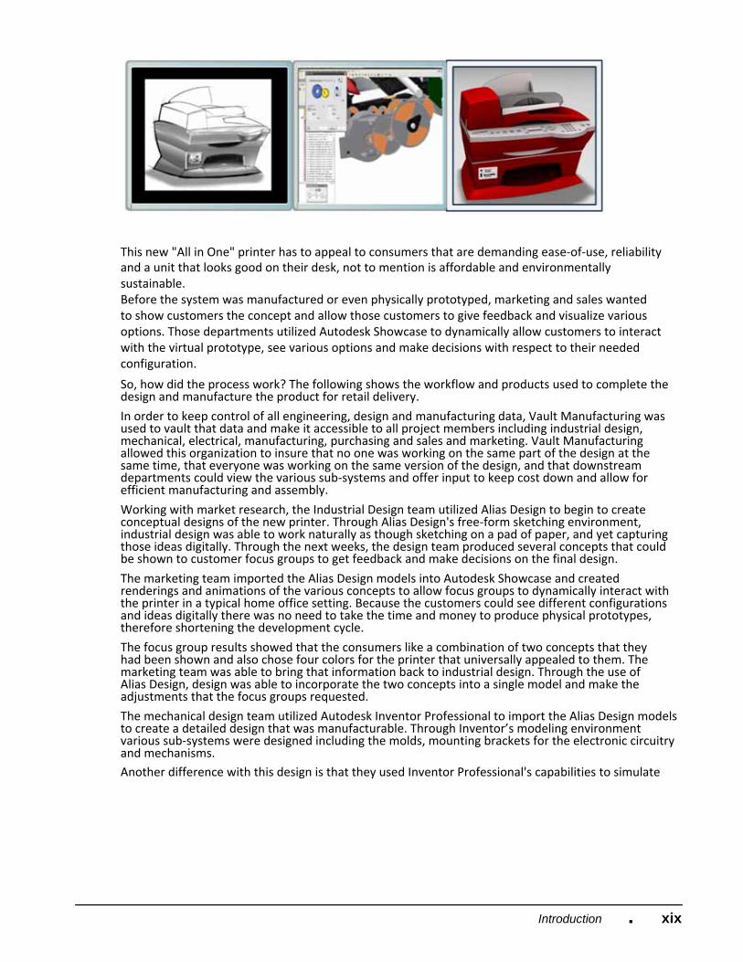
Our manufacturer designs and builds desktop printers but has fallen behind their competition with respect to cost and the look and feel of their product.
This manufacturer has determined that in order to keep up with competition and grow their market share, they will transition to Digital Prototyping, or virtually developing and building the product, collaborating with customers and communicating to all departments involved as the design develops.
xixIntroduction ■
This new "All in One" printer has to appeal to consumers that are demanding ease‐of‐use, reliability and a unit that looks good on their desk, not to mention is affordable and environmentally sustainable. Before the system was manufactured or even physically prototyped, marketing and sales wanted to show customers the concept and allow those customers to give feedback and visualize various options. Those departments utilized Autodesk Showcase to dynamically allow customers to interact with the virtual prototype, see various options and make decisions with respect to their needed configuration.
So, how did the process work? The following shows the workflow and products used to complete the design and manufacture the product for retail delivery.
In order to keep control of all engineering, design and manufacturing data, Vault Manufacturing was used to vault that data and make it accessible to all project members including industrial design, mechanical, electrical, manufacturing, purchasing and sales and marketing. Vault Manufacturing allowed this organization to insure that no one was working on the same part of the design at the same time, that everyone was working on the same version of the design, and that downstream departments could view the various sub‐systems and offer input to keep cost down and allow for efficient manufacturing and assembly.
Working with market research, the Industrial Design team utilized Alias Design to begin to create conceptual designs of the new printer. Through Alias Design's free‐form sketching environment, industrial design was able to work naturally as though sketching on a pad of paper, and yet capturing those ideas digitally. Through the next weeks, the design team produced several concepts that could be shown to customer focus groups to get feedback and make decisions on the final design.
The marketing team imported the Alias Design models into Autodesk Showcase and created renderings and animations of the various concepts to allow focus groups to dynamically interact with the printer in a typical home office setting. Because the customers could see different configurations and ideas digitally there was no need to take the time and money to produce physical prototypes, therefore shortening the development cycle.
The focus group results showed that the consumers like a combination of two concepts that they had been shown and also chose four colors for the printer that universally appealed to them. The marketing team was able to bring that information back to industrial design. Through the use of Alias Design, design was able to incorporate the two concepts into a single model and make the adjustments that the focus groups requested.
The mechanical design team utilized Autodesk Inventor Professional to import the Alias Design models to create a detailed design that was manufacturable. Through Inventor’s modeling environment various sub‐systems were designed including the molds, mounting brackets for the electronic circuitry and mechanisms. Another difference with this design is that they used Inventor Professional's capabilities to simulate

xx Introduction ■
various mechanisms and analyze parts for form, fit and function as well as safety considerations. As issues arose, electrical design and manufacturing could review the designs through Vault Manufacturing and Design Review to help make suggestions for improvement.
The electrical design team utilized a printed circuit board package and was able to export the physical model into Inventor using the IDF file format. One of the biggest changes in engineering was the ability to communicate design intent between the electrical and mechanical teams. While electrical engineers design the schematics and logic, it is typically up to the mechanical teams to mount and physically wire the electrical systems. In the past this was typically done during the physical prototyping phase and added time and cost to the product development cycle.
Technicians and engineers would run string from point to point to produce accurate lengths of cables or wires and use that string to make physical nailboards to produce prototype harnesses.
By utilizing Inventor Professional's routing capabilities the teams could accurately communicate the design intent, produce nail board drawings for cables, and simulate motion to insure that interferences wouldn't occur.
Throughout the design process the engineering team used Autodesk Showcase to work with sales and marketing to make quick design decisions that allowed the detailed design to continue without having to render the models and hold formal design review meetings.
Once the final configuration of the product was determined, the mechanical team could create detailed drawings in native DWG file format using DWG TruConnect. They could also export files for manufacturing, as well as create assembly instructions using Inventor’s presentation capability.
Prior to the release of the product, sales and marketing used Autodesk Showcase and 3DS Max to produce renderings and animations for customer facing printed material and an interactive website.
The end result was that this company reduced change orders, saved costs by communicating throughout the process with accurate, accessible information, beat timelines and produced a product that consumers wanted to purchase at a price point that was profitable for the company and within the consumers price expectation. The company might have also made more sustainable choices at key points in the design, engineering and manufacturing process, helping to reduce the number of physical prototypes and decrease waste.
By understanding that process and standards matter, capturing design intent from the beginning and not breaking the digital pipeline as the design evolves, Autodesk’s Digital Prototyping can assist any manufacturer to meet and exceed business goals.