AUTO CAD COMMANDS.pdf
34
AUTO CAD 2-D COMMANDS 07-EE-05 University of Engineering & Technology, Taxila. <<RMMAMCNFAEEUETT>> 1
-
Upload
rubia-iftikhar -
Category
Documents
-
view
96 -
download
11
description
its abt autocad commands
Transcript of AUTO CAD COMMANDS.pdf

AUTO CAD 2-D COMMANDS
07-EE-05
University of Engineering & Technology, Taxila.
<<RMMAMCNFAEEUETT>> 1

INTRODUCTION TO AUTO CAD
TOOL BARS MENU BAR TITLE BAR
DRAWING SHEET
CURSOR
COMMAND WINDOW
STATUS BAR
UCS
<<RMMAMCNFAEEUETT>> 2

1. We use different commands in command window for drawing.
2. After typing command in command window, we have to press ENTER to
activate that command.
3. For cancellation of used command, press ESC.
4. Here we can use FOUR types of ENTER as following.
o ENTER from keyboard.
o ENTER in numerical keys from keyboard.
o SPACE BAR from keyboard.
o RIGHT CLICK from mouse.
5. Next, sign of ENTER used, is shown in following diagram.
6. “SK” represents SHORT KEY of that specific command.
7. In AUTO CAD, one can perform drawing by following THREE methods:
o Main Menu
o Tool Bars
o Command Window
8. Here we use Command Window as it is quickest method.
9. Dialogue boxes have been added to make understanding effective.
10. The explanation immediate after the heading, is actually INTRODUCTION
of that specific command.
11. The information shown in italic, are actually the points or hints that you
follow to apply that command properly.
12. Some examples are also included here.
<<RMMAMCNFAEEUETT>> 3

UNITS For any kind of drawing, first we have to define units in which we will take measurements. SK = UN
A dialogue box will be there as:
Select desired units and then click OK. LIMITS Before drawing, we need a drawing sheet having our specific limits. So, we need to define drawing sheet limits. SK = LIMITS
<<RMMAMCNFAEEUETT>> 4

Specify lower left corner <0.0000, .0.0000>
Specify upper right corner <12.0000, 9.0000>
Your drawing sheet limits have been set. You can also click with mouse to specify the limit points instead of writing limits. LINE SK = L
LINE specify first point: (By left click) Specify next point:
Next point can be selected by following THREE methods:
1. Free Hand Line: By left click of mouse. 2. By Distance: Write distance value in command window and press ENTER. 3. By Length and Angle: @ D < θ
MLINE This command is used to draw a multiple line. SK = ML
EXAMPLE
<<RMMAMCNFAEEUETT>> 5

GRID Grid can be ON for sake of ease. Grid spacing can also be adjusted. SK = G
Specify grid spacing (x):
To make ON and OFF the grid: SK = F7
SNAP This command is used to select SNAP distance. SK = SN
Specify snap distance:
This is used to move the cursor along the grid points. SK = F9
ORTHO
<<RMMAMCNFAEEUETT>> 6

Aligns the line along x-axis or y-axis SK = F8 OSNAP For selection of different points as; End Point, Mid Point, Centre of Circle etc. SK = OS
A dialogue box will be appeared as:
After selection of these points, click OK. To switch ON or OFF this phenomenon of showing points in different cases
<<RMMAMCNFAEEUETT>> 7

SK = F3 ERASE SK = E
Select objects:
Object selection is done by two ways:
1. By Left Click 2. Dragging window by holding left click and putting it on the object.
TRIM Only dependent lines can be trimmed. Independent lines can not be trimmed as it can only be erased. SK = TR
Select object to trim: (By left click) TRIM FENCE SK = TR
Select object to trim: F
<<RMMAMCNFAEEUETT>> 8

First fence point: (By left click) Specify end point of line: (By left click)
EXTEND SK = EX
Select object to extend: (By left click) ZOOM REAL TIME This is used for any point to be zoomed. SK = Z
Putting window on object by dragging and then left click. ZOOM PREVIOUS This is used to go back to your previous zoom. SK = Z
<<RMMAMCNFAEEUETT>> 9

P
ZOOM ALL This is used to display your whole drawing sheet in front of you. SK = Z
A
ZOOM EXTEND This shows you drawing area only on the whole screen not your whole drawing sheet, irrespective of your limits. SK = Z
E
ZOOM DYNAMIC This will show a certain part of object in whole window. SK = Z
<<RMMAMCNFAEEUETT>> 10

D
OFFSET This will draw a parallel line to previous one in same length and at you given offset distance. SK = O
Specify offset distance:
Select object to offset: (By left click) Specify point on side to offset: (By left click) EXAMPLE
PAN This will move your drawing sheet in any direction. SK = P
By holding down left click.
<<RMMAMCNFAEEUETT>> 11

OR Holding down the SCROL of mouse and then move the mouse FITTED This will join two lines at your given radius. SK = F
R
Specify fillet radius:
Select first object: (By left click) Select second object: (By left click) EXAMPLE
COPY This is used to copy a single object. SK = CO / CP
<<RMMAMCNFAEEUETT>> 12

Select objects: (Dragging window by left click)
Specify base point or displacement: (By left click and move the mouse) Left click to paste the object. COPY MULTIPLE This is used to copy an object more than once at different places. SK = CO / CP
Select objects: (Dragging window by left click)
M
Specify base point or displacement: (By left click and move the mouse) Left click to paste the object at different places. RECTANGULAR ARRAY This will create a number of copies of an object in a rectangular shape. SK = -AR
Select objects: (Dragging window by left click)
<<RMMAMCNFAEEUETT>> 13

Enter the type of array: R
Enter the number of rows:
Enter number of columns:
Enter the distance between rows:
Enter the distance between columns:
EXAMPLE Rows = 2, Columns = 2, Distance b/w rows=12, Distance b/w columns=12
POLAR ARRAY This will create a number of copies of an object in a circular path. SK = -AR
<<RMMAMCNFAEEUETT>> 14
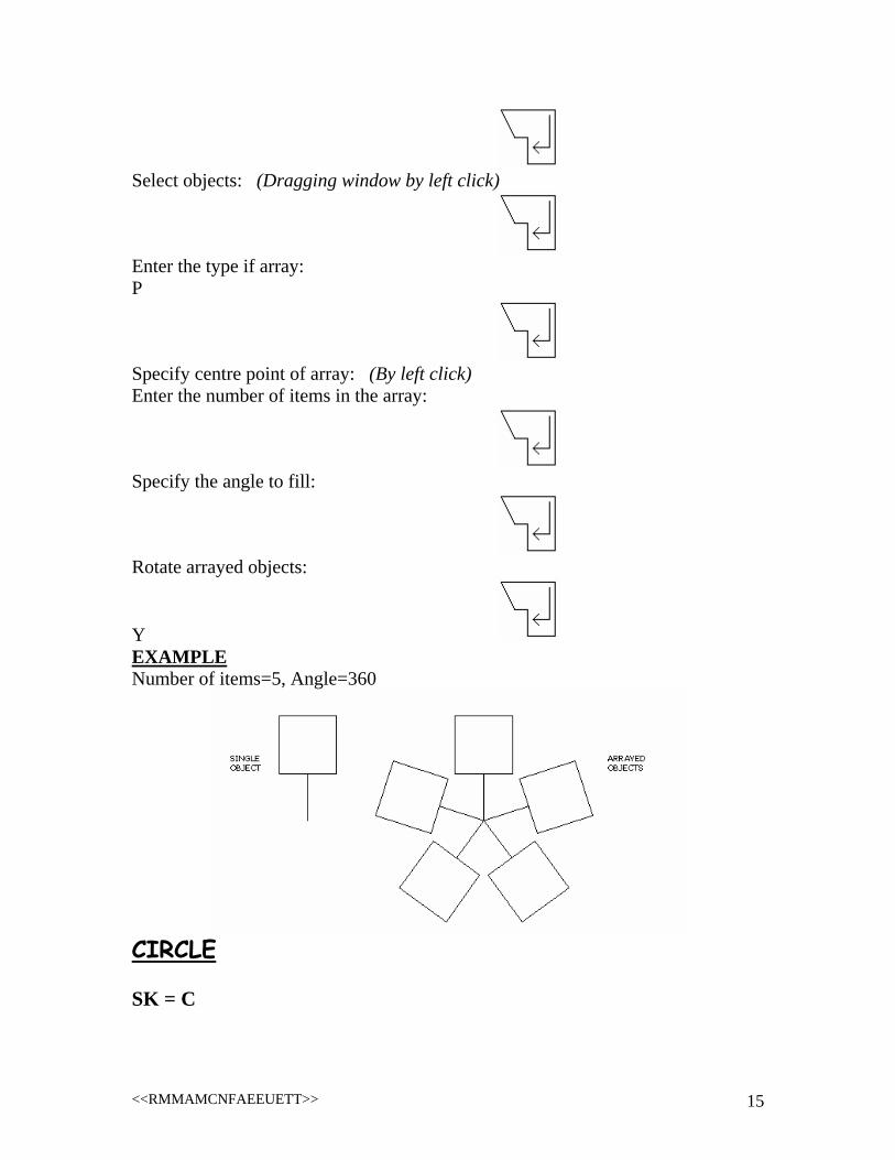
Select objects: (Dragging window by left click)
Enter the type if array: P
Specify centre point of array: (By left click) Enter the number of items in the array:
Specify the angle to fill:
Rotate arrayed objects:
Y EXAMPLE Number of items=5, Angle=360
CIRCLE SK = C
<<RMMAMCNFAEEUETT>> 15

CIRCLE Specify centre point for circle: (By left click) Specify radius for circle:
CHAMFER This command is used to join two lines with a third diagonal line. SK = CHA
D
Specify first chamfer distance:
Specify second chamfer distance:
Select first line: (By left click) Select second line: (By left click) EXAMPLE 1st and 2nd chamfer distances=2.0
<<RMMAMCNFAEEUETT>> 16

TEXT To add text to your drawing, make use of this command. SK = MT
Specify first corner: (By left click) Specify opposite corner: (By left click) A dialogue box will be opened. Now write your text, change settings as per your desire and then click OK. MIRROR This command will create a reflection of selected existing object. SK = MI
Select objects: (Dragging window by left click)
Specify first point of mirror line: (By left click) Specify second point of mirror line: (By left click)
EXAMPLE
ARC
<<RMMAMCNFAEEUETT>> 17

This command draws a curved line known as ARC. SK = A
ARC specify start point of arc: (By left click) Specify second point of arc: (By left click) Specify end point of arc: (By left click) ROTATE This will rotate the selected object at your given angle. SK = RO
Select objects: (Dragging window by left click)
Specify base point: (By left click) Specify rotation angle:
EXAMPLE
RECTANGLE SK = REC
<<RMMAMCNFAEEUETT>> 18

Specify first corner point: (By left click) Specify other corner point:
Other corner can be selected by TWO following methods:
1. Free Hand: By left click. 2. Giving Dimensions (Length and Width): @ L, W
SCALE This command is used to re-size your selected object by a factor given by you. SK = SC
Select objects: (Dragging window by left click)
Specify base point: (By left click) Specify scale factor:
EXAMPLE
<<RMMAMCNFAEEUETT>> 19
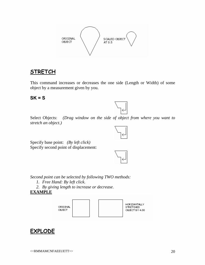
STRETCH This command increases or decreases the one side (Length or Width) of some object by a measurement given by you. SK = S
Select Objects: (Drag window on the side of object from where you want to stretch an object.)
Specify base point: (By left click) Specify second point of displacement:
Second point can be selected by following TWO methods:
1. Free Hand: By left click. 2. By giving length to increase or decrease.
EXAMPLE
EXPLODE
<<RMMAMCNFAEEUETT>> 20

This command is used to break an object into its line, arc and other pieces. SK = X
Select Objects: (Dragging window by left click)
EXAMPLE
REGION Sometimes, when you open your drawing file, the arcs and circles in the drawing are not properly curved. By use of this command, these arcs will be smooth. SK = RE
RAY This will draw a ray of infinite length in given direction. SK = RAY
Specify start point: (By left click) Specify through point: (By left click)
<<RMMAMCNFAEEUETT>> 21

LENGTHEN This command will lengthen your selected line to your given value. SK = LEN
T
Specify total length:
Select an object to change: (By left click) HATCH This command colors the selected object. Condition is that object should not be opened for hatch. SK = BH / H
A dialogue box in following form will be appeared.
<<RMMAMCNFAEEUETT>> 22

Click on PICK POINTS Click inside the object to be hatched
Select the color or texture or gradient and then click OK. POLYGON This command will create a geometrical object having number of sides given. SK = POL
POL enter number of sides:
<<RMMAMCNFAEEUETT>> 23

Specify centre of polygon: (By left click) Enter an option [Inscribed in circle / Circumscribed about circle]: (Enter “I” for first and “C” for second option)
Specify radius of circle:
BREAK This command is used to break a line between those two points that are given by mouse left click. SK = BR
BREAK select objects: (By left click) Specify second break point: (By left click) BOUNDARY If a closed abject consists of a number of lines, this command will join these lines to make a single object only. SK = BO
Following dialogue box will be there:
<<RMMAMCNFAEEUETT>> 24

Click on PICK POINTS Click inside the object
EXAMPLE
PEDIT This will work same as boundary does. SK = PE
<<RMMAMCNFAEEUETT>> 25

PEEDIT select poly line or [Multiple]: M
Select objects: (Dragging window by left click)
Convert Lines and Arcs to poly lines [Yes / No]: Y
Enter an option: J
Enter fuzz distance:
PEDIT This will work same as boundary does. SK = PE
PEEDIT select poly line or [Multiple]: (Select any line in object by left click) Do you want to turn it into one? <Y> Y
<<RMMAMCNFAEEUETT>> 26

Enter an option: J
Select objects: (Dragging window by left click)
DIVIDE This command divides a selected line into number of segments given. SK = DIV
Select object to divide: (By left click on line) Enter number of segments:
EXAMPLE
POINT STYLE Points in DIVIDE command may not visible, so change point style so that these points are visible. SK = DDPTYPE Following dialogue box will be appeared as:
<<RMMAMCNFAEEUETT>> 27

AREA & PERIMETER This command will give the total area bounded by closed object and its perimeter. SK = AA
Specify first corner point: (By left click) Specify next corner point or press ENTER for total: DIMENSION This command elaborates the drawing with necessary line lengths, widths and angles. Dimension settings can be set as: SK = D
<<RMMAMCNFAEEUETT>> 28

Set the settings and then click on SET CURRENT and CLOSE. From MAIN MENU drop down menu DIMENSIONS, any type of dimension can be selected as:
1. Linear: It only measures the ortho lines or lines parallel to x-axis and y-axis.
2. Aligned: It measures all type of lines such as horizontal, vertical and especially diagonal lines.
3. Radius: It gives radius of clicked circle. 4. Diameter: It gives diameter of clicked circle. 5. Angular: It gives the angle measurement between two clicked lines.
UNDO It takes you back to your previous action. SK = U
OR
<<RMMAMCNFAEEUETT>> 29
SK = Ctrl Z REDO It takes you to next action. SK = Ctrl Y SPLINE This will draw a free hand line in any direction. SK = SPL
Specify first point: (By left click) Specify next point: (By left click) Next point will be there until you press a ENTER THREE times.
DONUT This command is used to draw a pipe like object by giving its internal and external diameters. SK = DO
Specify inside diameter of donut:
<<RMMAMCNFAEEUETT>> 30

Specify outside diameter of donut:
Specify centre of donut: (By left click) EXAMPLE External & Internal Dias are 10.0, 5.0 respectively.
MATCH PROPERTY This command is used to match one object to other in color, line style, text matching or font matching etc. SK = MA
Select source object: (by left click) Select destination object(s): (Dragging window by left click) BLOCK If an object has its multiple use in drawing than a block is made of this object so that this object can be inserted at any point in drawing. Insertion of block is next command, here is only block making. SK = -B
<<RMMAMCNFAEEUETT>> 31

Enter block name:
Specify insertion base point: (By left click) Select objects: (Dragging window by left click)
INSERT This command is used to insert an existing block in drawing. SK = -I
Enter block name:
Specify insertion point: (By left click) Specify x scale factor:
Specify y scale factor:
Specify rotation angle:
PRINT SK = Ctrl P
<<RMMAMCNFAEEUETT>> 32

SAVE SK = Ctrl S ALIGN This command is used in insertion of some object from two points to two point target. SK = AL
Select objects: (Dragging window by left click)
Specify first source point: (By left click) Specify destination point: (By left click) Specify second source point: (By left click) Specify destination point: (By left click) Scale objects based on alignment points: N
LAYER Sometimes, we don’t require a specific object in our drawing. For this purpose, instead of erasing it, we make use of layers. If that object is made in its layer than this layer is made OFF to disappear this object and, again, it can be ON to get the object back in you drawing. How layer of an object is made, follow the following points: SK = -LA
<<RMMAMCNFAEEUETT>> 33

Enter option: M
Enter name for new layer:
Enter an option: C
New color:
Draw object in its presence. Now this layer can be ON and OFF from LAYER TOOL BAR. OPTIONS This command is very helpful in setting cursor size, colors of model and layouts, selection settings etc. SK = OP
<<RMMAMCNFAEEUETT>> 34