
Author's personal copy - utia.cas.cz
11
This article was published in an Elsevier journal. The attached copy is furnished to the author for non-commercial research and education use, including for instruction at the author’s institution, sharing with colleagues and providing to institution administration. Other uses, including reproduction and distribution, or selling or licensing copies, or posting to personal, institutional or third party websites are prohibited. In most cases authors are permitted to post their version of the article (e.g. in Word or Tex form) to their personal website or institutional repository. Authors requiring further information regarding Elsevier’s archiving and manuscript policies are encouraged to visit: http://www.elsevier.com/copyright
Transcript of Author's personal copy - utia.cas.cz

This article was published in an Elsevier journal. The attached copyis furnished to the author for non-commercial research and
education use, including for instruction at the author’s institution,sharing with colleagues and providing to institution administration.
Other uses, including reproduction and distribution, or selling orlicensing copies, or posting to personal, institutional or third party
websites are prohibited.
In most cases authors are permitted to post their version of thearticle (e.g. in Word or Tex form) to their personal website orinstitutional repository. Authors requiring further information
regarding Elsevier’s archiving and manuscript policies areencouraged to visit:
http://www.elsevier.com/copyright

Author's personal copy
Recognition of partially occluded and deformed binary objects q
Ondrej Horacek *, Jan Kamenicky, Jan Flusser
Institute of Information Theory and Automation, Academy of Sciences of the Czech Republic, Pod Vodarenskou vezı 4, 182 08 Prague 8, Czech Republic
Received 15 January 2006; received in revised form 26 June 2007Available online 25 October 2007
Communicated by H.H.S. Ip
Abstract
A method dealing with recognition of partially occluded and affine transformed binary objects is presented. The method is designedfor objects with smooth curved boundary. It divides an object into affine-invariant parts and uses modified radial vector for the descrip-tion of parts. Object recognition is performed via string matching in the space of radial vectors.� 2007 Elsevier B.V. All rights reserved.
Keywords: Image recognition; Partial occlusion; Affine transformation; Inflection point; Radial vector
1. Introduction
Recognition of objects under partial occlusions anddeformations caused by imaging geometry is one of themost difficult problems in computer vision. It is requiredalways when analyzing 2D images of a 3D scene.Although many methods trying to solve this task havebeen published, it still remains open. Clearly, there isno universal algorithm which would be ‘‘optimal’’ inall cases. Different methods should be designed for differ-ent classes of objects and for different groups of assumeddeformations.
This paper is devoted to objects with complicated curvedboundary. Such a boundary cannot be approximated by apolygon without loss of accuracy, so we do not employpolygonal-based methods at all. Furthermore, we assumethe objects are deformed by an unknown affine deforma-tion. When photographing a planar object arbitrary ori-ented in 3D space, the precise image deformation wouldbe a perspective projection. It is well-known it can be
approximated by affine transform when the object-to-cam-era distance is large comparing to the size of the object. Weuse the approximation by affine transformation because itis easy to handle, mainly because it is linear and its jaco-bian is constant in the image.
We introduce a method developed for the recognitionunder the above mentioned conditions. First, the object isdivided into parts which are defined by means of inflectionpoints of the object boundary. Then the shape of each partis described by a special kind of radial vector. Finally, theparameters of the affine deformation are estimated andclassification is performed by string matching in the spaceof radial vectors. The performance of the method is dem-onstrated by experiments.
2. Overview of current methods
Current methods can be classified into two major cate-gories. The methods of the first group divide the object intoaffine-invariant parts. Each part is described by some kindof ‘‘standard’’ global invariants, and the whole object isthen characterized by a string of vectors of invariants. Rec-ognition under occlusion is performed by maximum sub-string matching. Since inflection points of the boundaryare invariant to affine (and even projective) deformation
0167-8655/$ - see front matter � 2007 Elsevier B.V. All rights reserved.
doi:10.1016/j.patrec.2007.10.012
q This work has been supported by the Czech Ministry of Educationunder the Project No. 1M6798555601 (Research Center DAR).
* Corresponding author. Tel.: +420 776615670; fax: +420 284680730.E-mail addresses: [email protected] (O. Horacek), kamenik@utia.
cas.cz (J. Kamenicky), [email protected] (J. Flusser).
www.elsevier.com/locate/patrec
Available online at www.sciencedirect.com
Pattern Recognition Letters 29 (2008) 360–369

Author's personal copy
of a shape, they become a popular tool for the definition ofthe affine-invariant parts. This approach was used by Ibra-him and Cohen (1998), who described the object by arearatios of two neighboring parts. As a modification whichdoes not use inflection points, concave residua of convexhull could be used (Lamdan et al., 1988). For polygon-likeshapes, however, inflection points cannot be used. Instead,one can construct pats defined by three or four neighboringvertices. Yang and Cohen (1999) used area ratios of theparts to construct affine-invariants. Flusser (2002) furtherdeveloped their approach by finding more powerful invari-ant description of the parts. A similar method was success-fully tested for perspective projection by Rothwell et al.(1992).
The methods of the second group are ‘‘intrinsicallylocal’’, i.e. they do not divide the shape into subpartsbut rather describe the boundary in every point bymeans of its small neighborhood. In that way they trans-form the boundary to a so-called signature curve whichis invariant to affine/projective transform. Recognitionunder occlusion is again performed by substring match-ing in the space of signatures. Typical representativesof this group are differential invariants. They were dis-covered hundred years ago by Wilczynski (1906) whoproposed invariant signatures based on derivatives ofup to eighth-order. Weiss (1992) introduced differentialinvariants to the computer vision community. He pub-lished a series of papers on various invariants of ordersfrom four to six (Weiss, 1988; Bruckstein et al., 1997).Although differential invariants seemed to be promisingfrom theoretical point of view, they have been experi-mentally proven to be extremely sensitive to inaccuratesegmentation of the boundary, discretization errors andnoise.
Following methods dealing with recognition of trans-formed object could be relevant to our conditions, too.Mokhtarian and Abbasi (2002) used inflection points them-selves to characterize the boundary. They constructed so-called Curvature Scale Space and traced the position ofinflection points on different levels of image pyramid. Thetrajectories of the inflection points then served as objectdescriptors. Lamdan et al. (1988) used mutual position offour ‘‘interesting’’ points for the recognition. To verifythe received match, normalized concave areas weredescribed by the radial vector. There are also methodsbased on wavelet transform of the boundary. Tieng andBoles (1995) introduced wavelet-based boundary represen-tation, where affine invariance was achieved by enclosedarea contour parametrization. A similar approach wasused by Khalil and Bayeoumi (2001). However, the useof the wavelet-based methods in case of partial occlusionsis questionable.
3. Definition of affine-invariant parts
Both inflection points and central points of straight linesare affine-invariant, i.e. the properties ‘‘to be an inflection
point’’ and ‘‘to be a central point of a straight line’’ are pre-served under arbitrary nonsingular affine transform. Thus,we use these points (called ‘‘cut points’’ in the sequel) forthe construction of affine-invariant parts. We connect eachpair of neighboring cut points by a line. This line and thecorresponding part of the object boundary form a convexregion which may but need not to lie inside the originalobject (in Fig. 1c). The sequence of such parts carries effi-cient information about the object.
Detection of inflection points of discrete curves has beendiscussed in numerous papers. Let us recall that in the con-tinuous domain an inflection point is defined by a con-straint €xðtÞ _yðtÞ � _xðtÞ€yðtÞ ¼ 0, where x(t), y(t) represent aparametrization of the curve and the dots denote deriva-tives with respect to t. When this definition is directly con-verted to the discrete domain, it becomes very sensitive tosampling and noise. Thus, we propose a new robustmethod of curvature estimation.
For each boundary point, we construct a circle with itscenter in this point and having fixed radius (see Fig. 1a).We estimate the object boundary curvature asobject covered area
whole circle area� 1
2. The curvature is negative for convex
parts of the object boundary (less than a half of the circleis covered by the object), positive for concave parts, andequals zero for inflection points and straight lines. To sup-press small fluctuation of the curvature value, we apply asmoothing of the curvature series by convolution with anarrow Gaussian kernel. We get a smoothed curvaturegraph, such as in Fig. 1b.
Now we construct the division of the original object intoparts. Zero crossing points of the curvature and middlepoints of approximately zero-value segments on the curva-ture graph serve as cut points, it means points separatingthe object parts. We connect neighboring cut points bystraight line (see Fig. 1) which defines the object into parts.The parts, the area of which is less than a given threshold,are not considered.
4. Description of the parts
The object is represented by the parts defined in the pre-vious section. By adding a description of the shape of theindividual parts we get a description of the whole objectwhich is robust to occlusion. Robustness to occlusionmeans that if some part of the object boundary is missingor changed, only few elements of the feature vector arechanged. This is an important attribute. Note that tradi-tional global methods, for instance description of theobject by moment invariants or Fourier descriptors, donot have this property.
It would be possible to describe each part individuallyand eliminate the impact of the deformation by usingproper affine-invariants (moment invariants or Fourierdescriptors for instance). In such case, however, we donot employ important information that all the parts weredeformed by the same transformation. Including this con-sistency information in the object description can signifi-
O. Horacek et al. / Pattern Recognition Letters 29 (2008) 360–369 361

Author's personal copy
cantly increase the recognition performance. Thus, we pro-pose the following description of the parts by a modifiedradial vector, with included position of control points.See complete demo object description in Fig. 2a.
The spokes of the modified radial vector come from themiddle of the cutting line and they divide the part into sub-
parts of equal area. For each object part, they are con-structed as follows:
(1) Let n be the required number of the spokes (i.e. thelength of the radial vector).
(2) For each boundary point, do the following.
20 40 60 80 100 120 140 160
10
20
30
40
50
60
70
80
90
1000 50 100 150 200 250 300 350
0
0.05
—0.05
0.1
—0.1
0.15
—0.15
0.2
—0.2
20 40 60 80 100 120 140
10
20
30
40
50
60
70
80
Fig. 1. Definition of affine-invariant parts.
20 40 60 80 100 120 140
10
20
30
40
50
60
70
8050 100 150 200 250
20
40
60
80
100
120
140
160
Fig. 2. Description and matching of the demo object.
362 O. Horacek et al. / Pattern Recognition Letters 29 (2008) 360–369
Author's personal copy
(3) Calculate the area of the triangle between the currentboundary point, the neighboring boundary point,and the midpoint of the cutting line.
(4) If the cumulated area exceeds k/(n � 1) fraction ofthe total part area, we put the ending of the kth spokein the current boundary point.
(5) The radial vector consists of the n spokes lengths. Foreach part, we store its radial vector. It describes thepart shape completely.
(6) We store also absolute position of the part. It is rep-resented by position of its cut points and position ofthe mid-spoke end-point. This affine variant, comple-mentary information will allow us to recover thetransformation later.
The introduced modified radial vector divides the partinvariantly under affine transformation. Note that a classi-cal radial vector with constant-angle spokes distribution orconstant-boundary length spokes distribution has not sucha favorable property.
5. Matching
The image is classified by finding the longest and bestmatching section of the border (in Fig. 2b). This is realizedby comparing sequences of parts, represented by theirradial vectors, between the classified image and databaseobjects.
(1) Initialize minimal required match length P to 1 andsimilarity threshold Sthre to its minimal requiredvalue Smin (Smin is a user-defined parameter, we rec-ommend Smin = 0.8).
(2) For each part of the database object take a sequenceof this parts and P � 1 next parts.
(3) For each part of the image object take a sequence ofthis parts and P � 1 next parts.
(4) Calculate affine transformation T that transforms theimage parts sequence to the database sequence. Theleast square fit is applied to their cut points andmid-spoke end-point.
(5) Transform the spokes of the image radial vectors bythe transformation T and calculate their length, i.e.get their radial vectors.
(6) Compare each radial vector with the one from thedatabase by means of the similarity measure S
(described bellow).(7) If S > Sthre, these two sequences match. Mark these
sequences as the best ones, denote their length as Pbest
and its similarity as Sbest. Now try to make thesequence even longer, set P = P + 1, Sthre = Smin
and continue by step (4).(8) Otherwise reset the sequence length and similarity
threshold to the last best values P = Pbest andS = Sbest and continue the by loop (2), resp. (3).
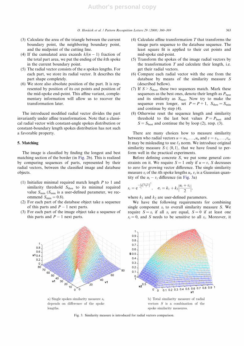
There are many choices how to measure similaritybetween who radial vectors u = u1, . . . ,un and v = v1, . . . ,vn.It may be misleading to use ‘2 norm. We introduce originalsimilarity measure S 2 h0,1i, that we have found to per-form well in the practical experiments.
Before defining concrete S, we put some general con-straints on it. We require S = 1 only if u = v, S decreasesto zero for growing vector difference. The single similaritymeasure si of the ith spoke lengths ui, vi is a Gaussian quan-tity of the ui � vi difference (in Fig. 3a)
si ¼ e� 1
r2i
ui�vi2ð Þ2
; ri ¼ k1 þ k2
ui þ vi
2
���
���;
where k1 and k2 are user-defined parameters.We have the following requirements for combining
single component si to overall similarity measure S. Werequire S = si if all si are equal, S = 0 if at least onesi = 0, and S needs to be sensitive to all si. Moreover, it
020
4060
80
010
2030
4050
6070
800
0.20.40.60.8
1
u1 v1
s1
0 0.1 0.2 0.3 0.4 0.5 0.6 0.7 0.8 0.9 10
0.5
10
0.10.20.30.40.50.60.70.80.9
1
s1
s2
S
Fig. 3. Similarity measure is introduced for radial vectors comparison.
O. Horacek et al. / Pattern Recognition Letters 29 (2008) 360–369 363
Author's personal copy
is reasonable to require S to be 0.75 if all but one si equal 1and one si equals 0.5 (in Fig. 3b). One can construct manyheuristic functions fulfilling the above constraints. Aftertesting several possibilities we decided to use the followingfunctions because of their simplicity and good performance
S ¼Pn
i¼1wi � siPni¼1wi
; wi ¼n� 2
si� ðn� 3Þ:
6. Experimental results
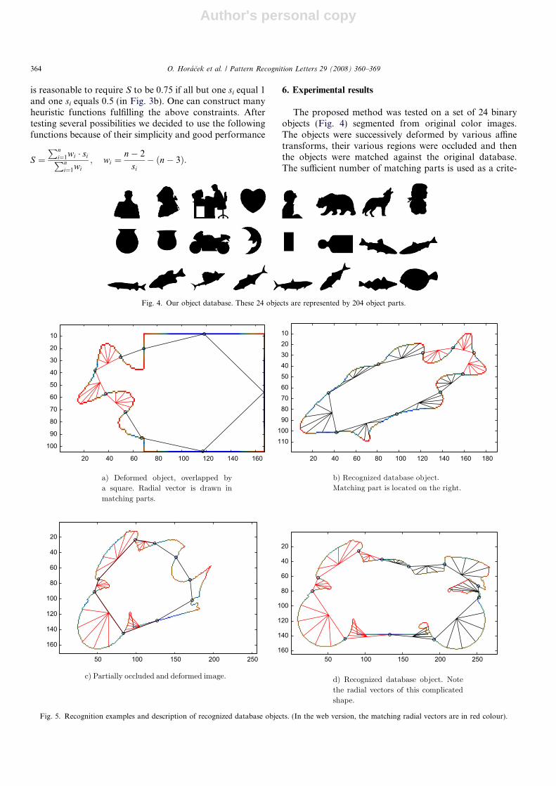
The proposed method was tested on a set of 24 binaryobjects (Fig. 4) segmented from original color images.The objects were successively deformed by various affinetransforms, their various regions were occluded and thenthe objects were matched against the original database.The sufficient number of matching parts is used as a crite-
Fig. 4. Our object database. These 24 objects are represented by 204 object parts.
20 40 60 80 100 120 140 160
10
20
30
40
50
60
70
80
90
100
20 40 60 80 100 120 140 160 180
102030405060708090
100110
50 100 150 200 250
20
40
60
80
100
120
140
160
50 100 150 200 250
20
40
60
80
100
120
140
160
Fig. 5. Recognition examples and description of recognized database objects. (In the web version, the matching radial vectors are in red colour).
364 O. Horacek et al. / Pattern Recognition Letters 29 (2008) 360–369

Author's personal copy
rion for match of the objects. This is in fact a well-knownprinciple of string matching.
For illustration, two examples are shown in Fig. 5. Onthe left-hand side, one can see partially occluded and trans-formed objects. The corresponding database objects (whichwere successfully found in both cases) are shown on theright-hand side. The control (inflection) points are high-lighted, their connecting lines define the division into parts.The spokes of the corresponding radial vectors are drawninside the matched parts of the image.
The modified radial vector describes the boundary witha good precision, the tolerance to a shape perturbations iscontrolled by user-defined parameters/thresholds. Thisenables an optimization for various types of shapes. Sur-prisingly, the boundary does not need to be a smooth curvewith well-defined inflection points. The method finds con-trol points even on polygonal parts (in Fig. 5a). Further-more, due to some tolerance threshold for the detectionof inflection points, we can obtain even some non-convexparts. We are able to construct radial vector also for these
non-convex parts (in Fig. 5d). Remind that our modifiedradial vector is created by dividing cumulative area whileproceeding the part boundary.
The object description and the result of a recognitionnaturally depends on the conditions of the experiment:character of the shapes, amount of occlusion, degree ofthe transformation, and noise. Before summing up statisti-cal experiments, let us focus on some situations in detail.As we can see in Fig. 6b, thanks to our robust curvatureestimation and similarity measure, the proposed method’sresistance to noise is quite good. It is possible to set themethod parameters to be even more robust to noise thanin the Fig. 6b, but the number of false positive matcheswould grow. Affine transformation was applied to theimages in Fig. 6c and 6d. The original object was recog-nized from the image, but some parts were not includedin the match. We will explain this phenomenon on follow-ing example.
At the bottom of Fig. 7 are two overlapped objects, thesecond one was transformed by a slightly harder transfor-
20 40 60 80 100 120 140 160 180
20
40
60
80
100
12020 40 60 80 100 120 140 160 180
20
40
60
80
100
120
50 100 150 200 250
20
40
60
80
100
120
140
160
18010 20 30 40 50 60 70 80 90 100
20
40
60
80
100
120
Fig. 6. Influence of affine transformation and noise to recognition.
O. Horacek et al. / Pattern Recognition Letters 29 (2008) 360–369 365
Author's personal copy
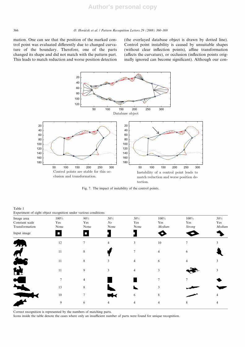
mation. One can see that the position of the marked con-trol point was evaluated differently due to changed curva-ture of the boundary. Therefore, one of the partschanged its shape and did not match with the pattern part.This leads to match reduction and worse position detection
(the overlayed database object is drawn by dotted line).Control point instability is caused by unsuitable shapes(without clear inflection points), affine transformation(affects the curvature), or occlusion (inflection points orig-inally ignored can become significant). Although our con-
50 100 150 200 250 300
20
40
60
80
100
120
50 100 150 200 250 300
20406080
100120140160180
50 100 150 200 250 300
20406080
100120140160180
Fig. 7. The impact of instability of the control points.
Table 1Experiment of eight object recognition under various conditions
Image area 100% 90% 50% 50% 100% 100% 50%
Constant scale Yes Yes No Yes Yes Yes YesTransformation None None None None Medium Strong Medium
Input image
12 7 4 3 10 7 3
11 8 7 4 6
11 8 3 4 6 4 3
11 9 3 4 3 3
7 4 7 7
13 8 3
10 7 6 8 4
9 6 4 4 4 8 4
Correct recognition is represented by the numbers of matching parts.Icons inside the table denote the cases where only an insufficient number of parts were found for unique recognition.
366 O. Horacek et al. / Pattern Recognition Letters 29 (2008) 360–369

Author's personal copy
trol point detection on a smooth boundary was improvedcomparing to traditional methods, it still remains a princi-pal problem. In general, we can say that the recognition isas good as the stability of the critical points.
Recognition under various conditions is summarized inTable 1. ‘‘Image area’’ denotes the size of the visible part ofthe test object (in per cent), ‘‘Constant scale of details’’indicates whether or not the same thresholds were usedfor database and test objects when detecting inflectionpoints, and ‘‘Transformation’’ means the significance ofthe deformation measured by skewing. The transformationwas chosen randomly to significant skewing and the occlu-sion was made automatically by straight white area. Theimage degradation is visualized on the square image inthe table header. The table itself shows the maximum num-ber of matching parts over all database objects. In allinstances where the maximum number of matching partswas greater than two the test objects were recognized cor-rectly. One or two matching parts does not ensure uniquecorrect match, so the classification can be wrong. Thesenot-recognized objects are represented inside the table byimage. Their problem is caused by strong deformation orlarge amount of occlusion which leads to instability of con-trol points.
We tested also the impact of a perspective transforma-tion on the recognition rate. We took several photos of
an object (trencher) with a camera in various positions.The object was segmented by single thresholding. Bound-ary of the segmented binary image was noisy and therewas notable impact of the object thickness. When the cam-era was about 1 meter from the trencher, the perspectiveeffect of the image transformation was not too strongand the object was recognized well (in Fig. 8). After wemoved the camera to about 25 cm from the object, thetransformation became obviously nonlinear (see Fig. 9).This is in contradiction with our original assumption aboutthe linearity of the deformation, and that is why the recog-nition may failed in some cases.
6.1. Comparison with area ratio method
The presented method is compared to Ibrahim andCohen (1998) paper, which is based on area ratio of shape
20 40 60 80 100 120 140 160 180 200 220
20
40
60
80
100
120
140
160
20
40
60
80
100
120
140
160
20 40 60 80 100 120 140 160 180 200 220
Fig. 8. Recognition under mild perspective projection. Both objects on the left were identified correctly.
20 40 60 80 100 120 140 160 180 200 20 40 60 80 100 120 140 160 180 200
20
40
60
80
100
120
140
20
40
60
80
100
120
140
Fig. 9. Recognition under heavy perspective projection. The object top left was identified correctly, while the object bottom left was misclassified becauseof significant nonlinear deformation.
Table 2The number of incorrect matches of area ratio and proposed method
Length of possible match Area ratio method The proposed method
4-part string 12 wrong matches 0 wrong matches3-part string 59 wrong matches 0 wrong matches2-part string 249 wrong matches 10 wrong matches
Thresholds of Ali’s method was set to classify our correct matches as goodones.
O. Horacek et al. / Pattern Recognition Letters 29 (2008) 360–369 367

Author's personal copy
parts. Although their algorithm was originally not devel-oped for recognition of partially occluded objects, it is suit-able for these conditions too. Their parts are bounded byinflection points as well.
Recognition power and discriminability of the methodswere tested by mutual matching of our 24 database objects(in Fig. 4). Note, the objects are represented by 204 partsand a match can be detected on each of their combination.Implementations of both algorithms use the same detectionof inflection points, therefore we can set a threshold of theAli’s method to classify our correct matches as good ones.In Table 2, counts of incorrectly matched neighboringparts are compared.
It is clear that the area ratio carries much less informa-tion than our modified radial vector. Proposed methodneeds only 3 parts for unique correct match, while the arearatio method requires 5 parts. These numbers are relevantto our database, different number of matching parts couldbe required for unique object match on some other data-base. Both methods can be affected by control points insta-bility. In Fig. 10 you can see one of the 10 worst two-partwrong matches of presented method and a sample of wrongfour-part match of area ratio method.
7. Conclusion
We presented a method for recognition of partiallyoccluded binary objects deformed by affine transforma-tion. The method uses local affine-invariant descriptionof the object boundary by means of inflection points
and radial vectors. When working with digital bound-ary, the major limitation of the method is stability ofinflection points. As the experiments demonstrated, ifthe curve has ‘‘prominent’’ inflection points, they areusually very stable under affine transformation and themethod works perfectly. On the other hand, in the caseof obscure boundary the inflection points may bedetected at different positions depending on the particu-lar transformation and/or occlusion and the recognitionmay fail.
Our experiment proved a good discrimination power ofthe method. On the given test set, we discovered that if themaximum number of matched boundary parts between theunknown object and the database element is greater thantwo, it always indicates a correct match. Thus, this thresh-old can be recommended for prospective real experimentstoo.
References
Bruckstein, A.M., Rivlin, E., Weiss, I., 1997. Scale-space semi localinvariants. Image Vision Comput. 15, 335–344.
Flusser, J., 2002. Affine invariants of convex polygons. IEEE Trans. ImageProcess., 11.
Ibrahim Ali, W.S., Cohen, F.S., 1998. Registering coronal histological 2-Dsections of a rat brain with coronal sections of a 3-D brain atlas usinggeometric curve invariants and B-spline representation. IEEE Trans.Medial Imag., 17.
Khalil, M.I., Bayeoumi, M.M., 2001. A dyadic wavelet affine invariantfunction for 2D shape recognition. IEEE Trans. PAMI 23, 1152–1163.
Lamdan, Y., Schwartz, J.T., Wolfson, H.J., 1988. Object recognition byaffine invariant matching. Comput. Vision Pattern Recognition, 335–344.
50 100 150 200 250
20406080
100120
50 100 150 200 250 300 350 400
20
40
60
80
100
10 20 30 40 50 60
10
20
30
40
50
60
50 100 150 200 250 300
20
40
60
80
100
120
Fig. 10. Example of too short matches for correct recognition, for both compared methods. Proposed method needs three parts for unique correct match,the area ratio method requires five parts. Two-part wrong match of the proposed method. Four-part wrong match of the area ratio method.
368 O. Horacek et al. / Pattern Recognition Letters 29 (2008) 360–369

Author's personal copy
Mokhtarian, F., Abbasi, S., 2002. Shape similarity under affine transform.Pattern Recognition 35, 31–41.
Rothwell, C.A., Zisserman, A., Forsyth, D.A., Mundy, J.L., 1992. Fastrecognition using algebraic invariants. Geometric Invariants in Com-puter Vision. MIT Press, Cambridge, pp. 398–407.
Tieng, Q.M., Boles, W.W., 1995. An application of wavelet-basedaffine-invariant representation. Pattern Recognition Lett. 16, 1287–1296.
Weiss, I., 1988. Projective Invariants of Shapes. Proc. Image Understand-ing Workshop, 1125–1134.
Weiss, I., 1992. Noise Resistant Invariants of Curves. GeometricInvariance in Computer Vision. MIT Press, Cambridge, pp. 135–156.
Wilczynski, E.J., 1906. Projective Differential Geometry of Curves andRuled Surfaces. B.G. Teubner, Leipzig.
Yang, Z., Cohen, F.S., 1999. Image registration and object recognitionusing affine invariants and convex hulls. IEEE Trans. Image Process. 8.
O. Horacek et al. / Pattern Recognition Letters 29 (2008) 360–369 369