AUTHORIZATIONS - Colorado State...
266
QUALITY ASSURANCE/QUALITY CONTROL DOCUMENTATION SERIES TITLE AUTOMATIC CAMERA SYSTEM MAINTENANCE TYPE STANDARD OPERATING PROCEDURE NUMBER 4120 DATE MARCH 1993 AUTHORIZATIONS TITLE NAME SIGNATURE ORIGINATOR Kristi Savig PROJECT MANAGER James H. Wagner PROGRAM MANAGER David L. Dietrich QA MANAGER Gloria S. Mercer OTHER REVISION HISTORY REVISION NO. CHANGE DESCRIPTION DATE AUTHORIZATIONS Reviewed; no changes necessary. March 1994 Reviewed; no changes necessary. March 1995 1.0 Changes to responsibilities and equipment. April 1996 Reviewed; no changes necessary. April 1997 Reviewed; no changes necessary. April 1998 2.0 Add digital camera/video system references. April 1999 Reviewed; no changes necessary. April 2000 Reviewed; no changes necessary. April 2001 -- continued --
Transcript of AUTHORIZATIONS - Colorado State...
QUALITY ASSURANCE/QUALITY CONTROL DOCUMENTATION SERIES TITLE
AUTOMATIC CAMERA SYSTEM MAINTENANCE
TYPE
STANDARD OPERATING PROCEDURE
NUMBER
4120
DATE
MARCH 1993
AUTHORIZATIONS
TITLE NAME SIGNATURE
ORIGINATOR Kristi Savig
PROJECT MANAGER James H. Wagner
PROGRAM MANAGER David L. Dietrich
QA MANAGER Gloria S. Mercer
OTHER
REVISION HISTORY
REVISION NO.
CHANGE DESCRIPTION DATE AUTHORIZATIONS
Reviewed; no changes necessary. March 1994
Reviewed; no changes necessary. March 1995
1.0 Changes to responsibilities and equipment. April 1996
Reviewed; no changes necessary. April 1997
Reviewed; no changes necessary. April 1998
2.0 Add digital camera/video system references. April 1999
Reviewed; no changes necessary. April 2000
Reviewed; no changes necessary. April 2001
-- continued --
QUALITY ASSURANCE/QUALITY CONTROL DOCUMENTATION SERIES TITLE
AUTOMATIC CAMERA SYSTEM MAINTENANCE
TYPE
STANDARD OPERATING PROCEDURE
NUMBER
4120
DATE
MARCH 1993
AUTHORIZATIONS
TITLE NAME SIGNATURE
ORIGINATOR Kristi Savig
PROJECT MANAGER James H. Wagner
PROGRAM MANAGER David L. Dietrich
QA MANAGER Gloria S. Mercer
OTHER
REVISION HISTORY
REVISION NO.
CHANGE DESCRIPTION DATE AUTHORIZATIONS
3.0 Add digital TIs and memory card references. August 2001
Reviewed; no changes necessary. August 2002
3.1 Add HRDC systems. August 2003
Number 4120 Revision 3.1 Date AUG 2003 Page i of i
TABLE OF CONTENTS Section Page 1.0 PURPOSE AND APPLICABILITY 1 2.0 RESPONSIBILITIES 2 2.1 Project Manager 2 2.2 Field Specialist 3 2.3 Data Coordinator 3 2.4 Site Operator 4 3.0 REQUIRED EQUIPMENT AND MATERIALS 4 3.1 Site Visit Equipment 4 3.2 Inventory 5 4.0 METHODS 5 4.1 Routine Site Operator Maintenance Procedures 7 4.2 Troubleshooting and Emergency Maintenance Procedures 8 4.3 Biannual Laboratory Maintenance Procedures 10
LIST OF FIGURES Figure Page 4-1 Automatic Camera System Field Quality Control Procedures 6

Number 4120 Revision 3.1 Date AUG 2003 Page 1 of 11
1.0 PURPOSE AND APPLICABILITY This standard operating procedure (SOP) outlines the quality assurance and quality control actions associated with the operation and maintenance of automatic visibility monitoring camera systems. Documenting visibility or visual events and trends is an important aspect of evaluating existing or potential impairment in Class I and other visibility-sensitive areas. Web-based high-resolution digital camera systems collect digital images for display on a Web page. Photography is an efficient way to document these events and trends and is an effective method of communicating visual relationships to decision-makers and to the public. Self-contained, automatic camera monitoring systems or time-lapse video monitoring systems are easily installed and operated. Camera-based monitoring, referred to as scene monitoring, is an effective, economical component of any visibility monitoring program. An automatic camera visibility monitoring station takes 35 mm slides or high-resolution digital images of a selected vista at user-selected times throughout the day. The station can also be outfitted with an 8 mm time-lapse camera or an SVHS time-lapse recorder to record the dynamics of visibility events. Day-to-day variations in visual air quality captured on 35 mm color film, compact memory cards (with varying storage capacity), 8 mm color movie film, SVHS videotape, or CD-ROMs can be used to:
• Document how vistas appear under various visual air quality, meteorological, and seasonal conditions. Scene characteristics include observer visual range, scene contrast, color, texture, and clarity.
• Record the frequency that various visual air quality conditions occur (e.g., incidence of
uniform haze, layered haze, or weather events).
• Provide a quality assurance reference for collocated measurements.
• Determine the visual sensitivity of individual areas or views to variations in ambient air quality.
• Identify areas of potential impairment.
• Estimate the optical properties of the atmosphere under certain conditions.
• Provide quality media for visually presenting program goals, objectives, and results to
decision-makers and to the public.
• Provide support data for the computer image modeling of potential impairment.
• Support color and human perception research. Slides, digital files, movie film, and videotape, however, do not provide quantitative information about the cause of visibility impairment. Aerosol and optical properties of the atmosphere must be independently monitored where cause and effect relationships are required.

Number 4120 Revision 3.1 Date AUG 2003 Page 2 of 11
In addition to visibility monitoring, time-lapse video systems can be used for a variety of other purposes, including:
• Environmental monitoring such as wildlife, waterflow, and source monitoring.
• Security monitoring for remote industrial sites and storage depots.
• Construction monitoring for building sites or highway and bridge construction.
• Event monitoring for remote weather documentation or highway and airport conditions.
• Recreation monitoring for ski areas and river rafting.
The automatic camera system maintenance quality assurance program consists of three (3) major categories:
• Routine Site Operator Maintenance Procedures Routine servicing and scheduled maintenance is carried out by site operators on a routine basis.
• Troubleshooting and Emergency Maintenance Procedures
Identifying and troubleshooting system malfunctions is carried out by site operators, a field specialist, and/or data coordinator, as required.
• Biannual Laboratory Maintenance Procedures
Intercomparison studies of film exposure, data collection, and equipment operations is carried out on an ongoing basis. Functional instrument checks, exposure calibrations, system lubrication, and preventative maintenance are carried out on a biannual basis.
A variety of camera monitoring configurations exist. Manufacturers change their model lines frequently as outdated models are discontinued and new models are introduced. Over the years, a variety of different camera and time-lapse systems have been applied to monitor visibility. Many of these systems still actively take visibility photographs in operational monitoring networks. This SOP is, therefore, supported by a series of monitoring configuration-specific technical instructions (TIs), as described in Section 4.0. 2.0 RESPONSIBILITIES 2.1 PROJECT MANAGER The project manager shall coordinate with the site operator, his/her supervisor, field specialist, and data coordinator concerning the schedule and requirements for routine maintenance or specific troubleshooting needs.
Number 4120 Revision 3.1 Date AUG 2003 Page 3 of 11
2.2 FIELD SPECIALIST The field specialist shall:
• Coordinate with the site operator, his/her supervisor, project manager, and data coordinator concerning the video monitoring schedule and requirements for routine maintenance or specific troubleshooting needs.
• Train the site operator in all phases of camera or video system maintenance. • Provide technical support to the site operator via telephone to assure high quality site
visits for camera or video monitoring systems. • Resolve problems reported by the site operator regarding camera or video monitoring
systems. • Document all technical support provided to the site operator regarding camera or
video monitoring systems. 2.3 DATA COORDINATOR The data coordinator shall:
• Coordinate with the site operator, his/her supervisor, project manager, and field specialist concerning the schedule and requirements for routine maintenance or specific troubleshooting needs.
• Verify that scheduled visits are performed and notify the site operator if he/she fails to make a scheduled visit.
• Identify possible camera or video system malfunctions and contact the site operator to schedule system troubleshooting visits.
• Review all site documentation completed by the site operator for accuracy and completeness, and file all documentation and correspondence.
• Provide technical support to the site operator via telephone to identify and resolve system problems. Document all technical support given to the site operator.
• Resolve problems reported by the site operator.
• Enter the results of all performed procedures into the site-specific Quality Assurance Database.
• Supply the site operator with all necessary monitoring supplies.
• Coordinate the replacement and repair of all system components and support hardware.
• Coordinate all aspects of biannual camera and video system maintenance. • Document all capital instrumentation changes and maintain inventory records in the
Air Resource Specialists, Inc. (ARS) Purchase Order/Inventory Database.
Number 4120 Revision 3.1 Date AUG 2003 Page 4 of 11
2.4 SITE OPERATOR The site operator shall:
• Coordinate with the site operator, his/her supervisor, project manager, and field specialist concerning the schedule and requirements for routine maintenance or specific troubleshooting needs.
• Schedule regular site maintenance visits and perform all procedures described in the instrument-specific TIs associated with this SOP.
• Thoroughly document all procedures on the Visibility Monitoring Status/Assessment Sheet or Time-Lapse Video Monitoring Status/Assessment Sheet and mail the white copy of the sheet to the data coordinator.
• Report any noted inconsistencies immediately to the data coordinator or field specialist.
• Schedule biannual maintenance with the data coordinator. 3.0 REQUIRED EQUIPMENT AND MATERIALS 3.1 SITE VISIT EQUIPMENT Site operators will maintain all necessary equipment and spare parts to accommodate routine, field, and emergency maintenance of the automatic camera and video systems. If required, factory-authorized maintenance and repair of monitoring equipment will be coordinated by ARS. Equipment and spare parts generally required to support routine servicing and on-site troubleshooting and emergency maintenance include the following:
• Voltmeter • Spare camera batteries • Spare timer batteries • Spare personal digital assistant (PDA) batteries (for digital camera systems) • Various size and type screwdrivers • Adjustable wrench • Keys for enclosure and any padlocks • Watch • Optical cleaning supplies • Site operator’s manual • Visibility Monitoring Status/Assessment Sheets
Number 4120 Revision 3.1 Date AUG 2003 Page 5 of 11
• Pen or pencil • Grease pencil • Film rolls or SVHS videotape cassettes • Memory cards (digital camera systems) • Padded mailing envelopes
A variety of cameras and monitoring configurations exist. Specific backup equipment requirements for each site will vary with the system configuration. Configuration-specific TIs detail the required equipment and materials for each site type. ARS has established service agreements with local factory-authorized repair facilities for Canon, Contax, Olympus, Minolta, Yashica, Panasonic, Sony, and Kodak manufactured products. These facilities are capable of providing prompt and thorough testing, preventive maintenance, and repair services, as described in Section 4.3. 3.2 INVENTORY It is imperative that all capital instrumentation changes made as a result of routine and emergency maintenance be thoroughly documented and maintained in the ARS Purchase Order/Inventory Database. Any on-site equipment changes made should be documented by the site operator on a Visibility Monitoring Status/Assessment Sheet or on a Time-Lapse Video Monitoring Status/Assessment Sheet. Specific model and serial number items tracked are discussed further in the instrument-specific troubleshooting and emergency maintenance TIs (see Section 4.2). 4.0 METHODS This section includes three (3) subsections: 4.1 Routine Site Operator Maintenance Procedures 4.2 Troubleshooting and Emergency Maintenance Procedures 4.3 Biannual Laboratory Maintenance Procedures
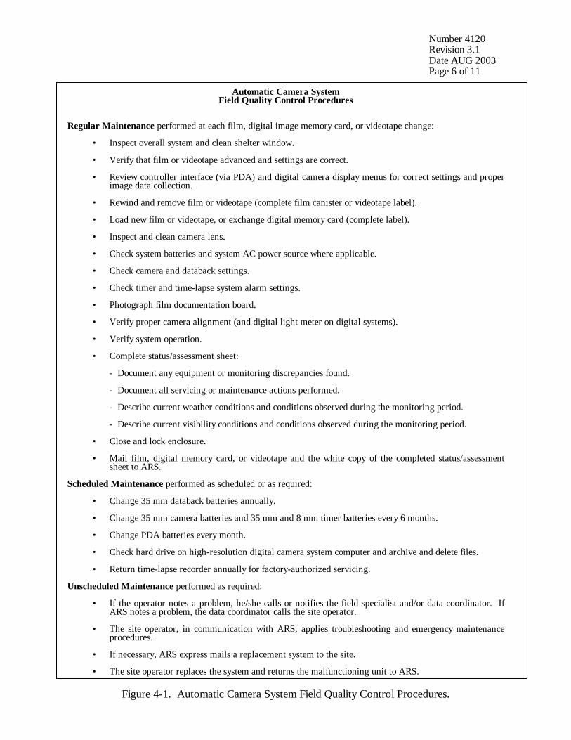
Methods and procedures described in these subsections are summarized in Figure 4-1.
Number 4120 Revision 3.1 Date AUG 2003 Page 6 of 11
Automatic Camera System Field Quality Control Procedures
Regular Maintenance performed at each film, digital image memory card, or videotape change: • Inspect overall system and clean shelter window. • Verify that film or videotape advanced and settings are correct. • Review controller interface (via PDA) and digital camera display menus for correct settings and proper
image data collection. • Rewind and remove film or videotape (complete film canister or videotape label). • Load new film or videotape, or exchange digital memory card (complete label). • Inspect and clean camera lens. • Check system batteries and system AC power source where applicable. • Check camera and databack settings. • Check timer and time-lapse system alarm settings. • Photograph film documentation board. • Verify proper camera alignment (and digital light meter on digital systems). • Verify system operation. • Complete status/assessment sheet: - Document any equipment or monitoring discrepancies found. - Document all servicing or maintenance actions performed. - Describe current weather conditions and conditions observed during the monitoring period. - Describe current visibility conditions and conditions observed during the monitoring period. • Close and lock enclosure. • Mail film, digital memory card, or videotape and the white copy of the completed status/assessment
sheet to ARS. Scheduled Maintenance performed as scheduled or as required: • Change 35 mm databack batteries annually. • Change 35 mm camera batteries and 35 mm and 8 mm timer batteries every 6 months. • Change PDA batteries every month. • Check hard drive on high-resolution digital camera system computer and archive and delete files. • Return time-lapse recorder annually for factory-authorized servicing. Unscheduled Maintenance performed as required: • If the operator notes a problem, he/she calls or notifies the field specialist and/or data coordinator. If
ARS notes a problem, the data coordinator calls the site operator. • The site operator, in communication with ARS, applies troubleshooting and emergency maintenance
procedures. • If necessary, ARS express mails a replacement system to the site. • The site operator replaces the system and returns the malfunctioning unit to ARS.
Figure 4-1. Automatic Camera System Field Quality Control Procedures.
Number 4120 Revision 3.1 Date AUG 2003 Page 7 of 11
Site operators are trained and supplied with a Site Operator's Manual for Automatic Visibility Monitoring Camera Systems, Site Operator’s Manual for Remote High-Resolution Digital Camera Systems, or Site Operator’s Manual for High-Resolution Digital Camera Systems. These manuals contain standard operating procedures and technical instructions applicable to the specific camera or video monitoring equipment located at the sites. Additional manufacturers’ instructions booklets and pertinent maintenance documentation forms are also provided. 4.1 ROUTINE SITE OPERATOR MAINTENANCE PROCEDURES Routine servicing schedules are based on the number of photographs or images taken each day. A common 35 mm or digital camera monitoring schedule includes taking three photographs a day at 0900, 1200, and 1500. Assuming this monitoring schedule, site operators service the camera approximately every 10 days to change film (digital cameras require exchanging the memory card), check the performance of the camera(s), clean the system components, and perform scheduled preventive maintenance. A common 8 mm or time-lapse video monitoring schedule includes monitoring continuously (e.g., 1 frame per minute) during the daylight hours of 0800 through 1800. Assuming this monitoring schedule, site operators service the camera approximately every 7 days (8 mm cameras) or 14 days (video systems), to change film, check the performance of the camera(s), clean the system components, and perform scheduled preventive maintenance. Regular servicing and the identification and documentation of film rolls, memory cards, or videotapes are essential. During each routine site visit, the operator will thoroughly document all pertinent data collection information, any maintenance performed, and any equipment or monitoring inconsistencies on the Visibility Monitoring Status/Assessment Sheet or Time-Lapse Video Monitoring Status/Assessment Sheet. Completed sheets are mailed with each roll of film, memory card, or videotape. If operator entries on the sheet indicate that further action is necessary, immediate corrective action will be taken by the data coordinator.
Throughout the monitoring effort, ARS and site operators maintain close personal communication. Operators are encouraged to call or notify ARS if they have any questions or problems. A data coordinator and/or field specialist is available during normal business hours (0800-1700 MST) to provide telephone assistance to site operators. A telephone answering/message system operates during non-business hours. ARS may be reached using the following methods: Telephone: 970/484-7941 Fax: 970/484-3423 E-mail: [email protected] Instrument-specific routine site operator maintenance procedures are provided in detail in the following TIs:
• TI 4120-3100 Routine Site Operator Maintenance Procedures for 35 mm Automatic Camera System - Canon EOS 630
• TI 4120-3110 Routine Site Operator Maintenance Procedures for 35 mm
Automatic Camera System - Contax 167MT
Number 4120 Revision 3.1 Date AUG 2003 Page 8 of 11
• TI 4120-3120 Routine Site Operator Maintenance Procedures for 35 mm Automatic Camera System - Contax 137 MA
• TI 4120-3130 Routine Site Operator Maintenance Procedures for 35 mm
Automatic Camera System - Olympus OM2N • TI 4120-3140 Routine Site Operator Maintenance Procedures for 35 mm
Automatic Camera System - Pentax PZ-20 • TI 4120-3150 Routine Site Operator Maintenance Procedures for 35 mm
Automatic Camera System – Pentax ZX-10 • TI 4120-3200 Routine Site Operator Maintenance Procedures for 8 mm
Automatic Camera System - Minolta XL 401/601 • TI 4120-3210 Routine Site Operator Maintenance Procedures for 8 mm
Automatic Camera System - Minolta D12 • TI 4120-3650 Routine Site Operator Maintenance Procedures for SVHS Time-
Lapse Video Camera System at DNPP – Sony SSC-S20 Camera, Panasonic AG-6740 SVHS VCR, and Panasonic CT1384Y Monitor
• TI 4120-3655 Routine Site Operator Maintenance Procedures for SVHS Time-
Lapse Video Camera System at Garner Hill – Sony SSC-S20 Camera, Pelco PT1250 Series Pan/Tilt, RWI 30CM Microwave Antenna, and Panasonic CT1384Y Monitor
• TI 4120-3660 Routine Site Operator Maintenance Procedures for SVHS Time-
Lapse Video Camera System at HCCP – Panasonic AG-6740 SVHS VCR and Sony Monitor
• TI 4120-3800 Routine Site Operator Maintenance Procedures for Remote High-
Resolution Digital Camera Systems (RDCS-100)
• TI 4120-3850 Routine Site Operator Maintenance Procedures for the High- Resolution Digital Camera System (HRDC)
4.2 TROUBLESHOOTING AND EMERGENCY MAINTENANCE PROCEDURES Maintaining a monitoring camera system includes prompt detection and emergency maintenance when the system fails to function properly. The troubleshooting and emergency maintenance process should progress as outlined below to ensure ongoing, consistent data collection.
• A system malfunction is detected by the site operator during routine maintenance of the system or by the data coordinator during review of processed film, memory card, videotape, or during review of image postings on the Internet.
Number 4120 Revision 3.1 Date AUG 2003 Page 9 of 11
• The site operator applies defined troubleshooting procedures to test the system and notifies the data coordinator of his/her findings. The data coordinator attempts to diagnose the problem and suggest specific action. The operator initiates the corrective action, tests the system, and again notifies the data coordinator of his/her findings.
• If the system appears to be operating normally, the operator returns it to service and
visits the site periodically before the next regularly scheduled visit. • When a camera-related or video recording problem cannot be identified or resolved by
the site operator, or if the site operator is not available to address the malfunction, the data coordinator ships a complete backup system or replacement components to the site as quickly as possible. Site operators exchange the equipment and ship the malfunctioning unit to ARS for evaluation and repair.
• The operator documents all problems, troubleshooting, and corrective actions on the
Visibility Monitoring Status/Assessment Sheet or Time-Lapse Video Monitoring Status/Assessment Sheet. The documentation should include:
- Date of noted malfunction - Actual or estimated amount of data loss - Steps taken to test the system components - Corrective action taken - Current operational status
• All troubleshooting and emergency maintenance communications documentation will be retained in the site-specific Quality Assurance Database for future reference. The data coordinator will continue to monitor processed film for reoccurrences or resolution of the problem.
Instrument-specific troubleshooting steps are provided in detail in the following TIs:
• TI 4120-3300 Troubleshooting and Emergency Maintenance Procedures for 35 mm Automatic Camera System - Canon EOS 630
• TI 4120-3310 Troubleshooting and Emergency Maintenance Procedures for
35 mm Automatic Camera System - Contax 167MT • TI 4120-3320 Troubleshooting and Emergency Maintenance Procedures for
35 mm Automatic Camera System - Contax 137 MA • TI 4120-3330 Troubleshooting and Emergency Maintenance Procedures for
35 mm Automatic Camera System - Olympus OM2N • TI 4120-3340 Troubleshooting and Emergency Maintenance Procedures for
35 mm Automatic Camera System - Pentax PZ-20

Number 4120 Revision 3.1 Date AUG 2003 Page 10 of 11
• TI 4120-3350 Troubleshooting and Emergency Maintenance Procedures for 35 mm Automatic Camera System – Pentax ZX-10
• TI 4120-3400 Troubleshooting and Emergency Maintenance Procedures for
8 mm Automatic Camera System - Minolta XL 401/601 • TI 4120-3410 Troubleshooting and Emergency Maintenance Procedures for
8 mm Automatic Camera System - Minolta D12 • TI 4120-3750 Troubleshooting and Emergency Maintenance Procedures for
SVHS Time-Lapse Video Camera System at DNPP – Sony SSC-S20 Camera, Panasonic AG-6740 SVHS VCR, and Panasonic CT1384Y Monitor
• TI 4120-3755 Troubleshooting and Emergency Maintenance Procedures for
SVHS Time-Lapse Video Camera System at Garner Hill – Sony SSC-S20 Camera, Pelco PT1250 Series Pan/Tilt, RWI 30CM Microwave Antenna, and Panasonic CT1384Y Monitor
• TI 4120-3760 Troubleshooting and Emergency Maintenance Procedures for
SVHS Time-Lapse Video Camera System at HCCP – Panasonic AG-6740 SVHS VCR and Sony Monitor
• TI 4120-3900 Troubleshooting and Emergency Maintenance Procedures for
Remote High-Resolution Digital Camera Systems (RDCS-100) • TI 4120-3950 Troubleshooting and Emergency Maintenance Procedures for
the High-Resolution Digital Camera System (HRDC) 4.3 BIANNUAL LABORATORY MAINTENANCE PROCEDURES Internal quality assurance of automatic camera equipment is based primarily on visual review of developed film, archived digital image files, or videotape. Photographic media handling and review procedures are fully discussed in SOP 4305, Collection of Scene Monitoring Photographic Film, Videotape, and Digital Images. Alignment, exposure, and data collection efficiency can all be assessed from review of collected media. Any noted problems will initiate corrective action. Using quality site operators, verification of system performance and correction of identified problems can be successfully accomplished. On rare occasions when unresolvable problems persist, a field specialist will visit a site to repair, reconfigure, or reinstall a malfunctioning system, and will retrain the site operator. Ongoing review of photographic media and site operator identified problems often initiates corrective actions. Servicing of all cameras and support systems is performed by mailing replacement parts and/or systems to the site operators and repairing those components returned by the site operators. Operational camera systems are biannually cycled out of the monitoring network. Shelters remain in place and the cameras and timers are cycled for laboratory maintenance. Automatic camera and video system maintenance is normally provided by local factory-authorized repair facilities capable of performing the following:
Number 4120 Revision 3.1 Date AUG 2003 Page 11 of 11
• Cleaning, lubrication, and adjustment of all camera components • Automatic exposure calibration checks • Ambient/cold testing of:
- Current draw - Shutter speed and curtain travel time - Automatic exposure meter readout - Film transport
• Lens focus checks (and disabling of the soft focus mechanism in Canon 135 mm lenses)
• Battery and camera cabling integrity checks and necessary repair • Timer circuitry checks • Cleaning the VCR’s head drum assembly, pinch roller, and capstan • Checking the VCR’s back tension and take-up torque • Checking and adjusting videotape path • Checking VCR play and rewind performance
Additional preventive maintenance performed on each serviced system includes:
• Camera system battery replacements • Timer system battery replacements • Lens cleaning • Operational testing
Instrument-specific routine and annual laboratory maintenance procedures are provided in detail in the following TIs:
• TI 4120-3500 Biannual Laboratory Maintenance Procedures for 35 mm Automatic Camera Systems
• TI 4120-3510 Biannual Laboratory Maintenance Procedures for 8 mm
Automatic Time-Lapse Camera Systems

QUALITY ASSURANCE/QUALITY CONTROL DOCUMENTATION SERIES TITLE
ROUTINE SITE OPERATOR MAINTENANCE PROCEDURES FOR 35 MM AUTOMATIC CAMERA SYSTEM – CANON EOS 630
TYPE
TECHNICAL INSTRUCTION
NUMBER
4120-3100
DATE
MARCH 1993
AUTHORIZATIONS
TITLE NAME SIGNATURE
ORIGINATOR Kristi Savig
PROJECT MANAGER James H. Wagner
PROGRAM MANAGER David L. Dietrich
QA MANAGER Gloria S. Mercer
OTHER
REVISION HISTORY
REVISION NO.
CHANGE DESCRIPTION DATE AUTHORIZATIONS
Reviewed; no changes necessary. March 1994
Reviewed; no changes necessary. March 1995
1.0 Revise illustrations and forms. June 1996
Reviewed; no changes necessary. June 1997
Reviewed; no changes necessary. June 1998
Reviewed; no changes necessary. June 1999
Reviewed; no changes necessary. June 2000
1.1 Delete references to 9v battery in timer. September 2000
-- continued --
QUALITY ASSURANCE/QUALITY CONTROL DOCUMENTATION SERIES TITLE
ROUTINE SITE OPERATOR MAINTENANCE PROCEDURES FOR 35 MM AUTOMATIC CAMERA SYSTEM – CANON EOS 630
TYPE
TECHNICAL INSTRUCTION
NUMBER
4120-3100
DATE
MARCH 1993
AUTHORIZATIONS
TITLE NAME SIGNATURE
ORIGINATOR Kristi Savig
PROJECT MANAGER James H. Wagner
PROGRAM MANAGER David L. Dietrich
QA MANAGER Gloria S. Mercer
OTHER
REVISION HISTORY
REVISION NO.
CHANGE DESCRIPTION DATE AUTHORIZATIONS
Reviewed; no changes necessary. September 2001
Reviewed; no changes necessary. September 2002
Number 4120-3100 Revision 1.1 Date SEP 2000 Page i of ii
TABLE OF CONTENTS Section Page 1.0 PURPOSE AND APPLICABILITY 1 2.0 RESPONSIBILITIES 1 2.1 Project Manager 1 2.2 Field Specialist 1 2.3 Data Coordinator 2 2.4 Site Operator 2 3.0 REQUIRED EQUIPMENT AND MATERIALS 2 3.1 Site Visit Equipment 2 3.2 Inventory 4 4.0 METHODS 4 4.1 Routine Servicing 4 4.1.1 Status/Assessment Sheet General Information 9 4.1.2 Status/Assessment Sheet Film Removal Section 12 4.1.3 Status/Assessment Sheet Film Loading Section 13 4.1.4 Mailing the Film and Completed Status/Assessment Sheet 19 4.2 Scheduled Maintenance 20 4.2.1 Film and Film Storage 20 4.2.2 Changing System Batteries 21 4.2.3 System Reconfiguration 23 4.2.4 On-Site Data Control 27
LIST OF FIGURES Figure Page 4-1 Canon EOS System Components 6 4-2 Automatic 35 mm Camera System Tripod Assembly 7 4-3 Automatic 35 mm Camera System Enclosure 8 4-4 Example Visibility Monitoring Status/Assessment Sheet for the Canon EOS 630 Automatic Camera System 10
Number 4120-3100 Revision 1.1 Date SEP 2000 Page ii of ii
LIST OF FIGURES (CONTINUED) Figure Page 4-5 Completed Example of an Automatic Camera Visibility Monitoring Status/Assessment Sheet 11 4-6 Photographic Documentation Board 16 4-7 Paragon Timer Battery Configuration 23 4-8 Canon EOS 630 Display Panel 24 4-9 Canon Quartz Date Back E Display 24 4-10 Photographic Monitoring Network Quality Assessment Log 29
LIST OF TABLES Table Page 4-1 Automatic Camera System Field Quality Control Procedures 5
Number 4120-3100 Revision 1.1 Date SEP 2000 Page 1 of 29
1.0 PURPOSE AND APPLICABILITY The purpose of routine site operator maintenance is to assure quality data capture and minimize data loss by performing and documenting scheduled operational checks and preventive maintenance. This technical instruction (TI) describes the steps of a routine site visit, scheduled maintenance, and on-site data control for the Canon EOS 630 35 mm camera system. Routine servicing schedules are based on the number of photographs taken each day. Assuming a three-photograph per day schedule, site operators service the camera approximately every 10 days to change film, check the performance of the camera system, clean system components, and perform troubleshooting and/or emergency maintenance as required. Preventive maintenance site visits are performed every six months or as required by the data coordinator. The effective performance and documentation of each of these tasks is the key to quality data collection and minimal data loss. Site operators should be fully trained and supplied with a Site Operator’s Manual for Automatic Visibility Monitoring Camera Systems that contains detailed routine site operator maintenance and troubleshooting procedures for the specific camera monitoring system(s) located at the site. Additional manufacturer instruction booklets and a supply of Visibility Monitoring Status/Assessment Sheets are also provided. Close personal communications should be maintained between Air Resource Specialists, Inc. (ARS) and site operators throughout the monitoring effort. Operators are encouraged to call or notify ARS if they have any questions or problems. Many problems can be fully resolved over the telephone. 2.0 RESPONSIBILITIES 2.1 PROJECT MANAGER The project manager shall coordinate with the site operator, his/her supervisor, field specialist, and data coordinator concerning the schedule and requirements for routine maintenance. 2.2 FIELD SPECIALIST The field specialist shall:
• Coordinate with the project manager, the site operator, his/her supervisor, and data coordinator concerning the schedule and requirements for routine maintenance.
• Train the site operator in all phases of camera system maintenance.
• Provide technical support to the site operator via telephone to assure high quality site
visits.
• Resolve problems reported by the site operator.
• Document all technical support provided to the site operator.
Number 4120-3100 Revision 1.1 Date SEP 2000 Page 2 of 29
2.3 DATA COORDINATOR The data coordinator shall:
• Coordinate with the project manager, the site operator, his/her supervisor, and field specialist concerning the schedule and requirements for routine maintenance.
• Verify that scheduled visits are performed and notify the site operator if he/she fails to
make a scheduled visit.
• Review all site documentation completed by the site operator for accuracy and completeness. File all documentation and correspondence.
• Resolve problems reported by the site operator.
• Enter the results of all performed procedures into the site-specific Quality Assurance
Database.
• Supply the site operator with all necessary monitoring supplies.
• Coordinate the replacement and repair of all malfunctioning units.
• Document all capital instrumentation changes and maintain inventory records in the ARS Purchase Order/Inventory Database.
2.4 SITE OPERATOR The site operator shall:
• Coordinate with his/her supervisor, the project manager, data coordinator, and field specialist concerning the schedule and requirements for routine maintenance.
• Schedule regular site maintenance visits and perform all procedures described in this TI.
• Thoroughly document all procedures on the Visibility Monitoring Status/Assessment
Sheet; mail the white copy of the completed sheet to the data coordinator and maintain an on-site file of the yellow copy.
• Immediately report any noted inconsistencies to the data coordinator or field specialist.
3.0 REQUIRED EQUIPMENT AND MATERIALS 3.1 SITE VISIT EQUIPMENT Equipment and materials generally required to support a routine site visit or scheduled maintenance include:
• Medium and small flat-blade screwdriver
• Small Phillips-head screwdriver
Number 4120-3100 Revision 1.1 Date SEP 2000 Page 3 of 29
• Medium adjustable wrench
• Keys for enclosure and padlocks
• Voltmeter
• Backup camera, databack, and timer batteries: - Canon EOS 630: - one 6 V lithium battery - Canon Quartz Date Back E: - one 3 V lithium battery - Paragon EC72D: - two 6 V lantern batteries
• Watch
• Lens cleaner and lens paper
• Site Operator’s Manual for Automatic Visibility Monitoring Camera Systems containing:
- SOP 4120, Automatic Camera System Maintenance (IMPROVE Protocol) - TI 4120-3100, Routine Site Operator Maintenance Procedures for 35 mm
Automatic Camera System - Canon EOS 630 - TI 4120-3300, Troubleshooting and Emergency Maintenance Procedures for
35 mm Automatic Camera System - Canon EOS 630 - Automatic 35 mm Camera System User’s Manual - Manufacturers’ instruction booklets - Visibility Monitoring Status/Assessment Sheets - Film canister labels
• Pen or pencil
• Grease pencil
• Supplemental visibility monitoring film
• Padded mailing envelopes
Number 4120-3100 Revision 1.1 Date SEP 2000 Page 4 of 29
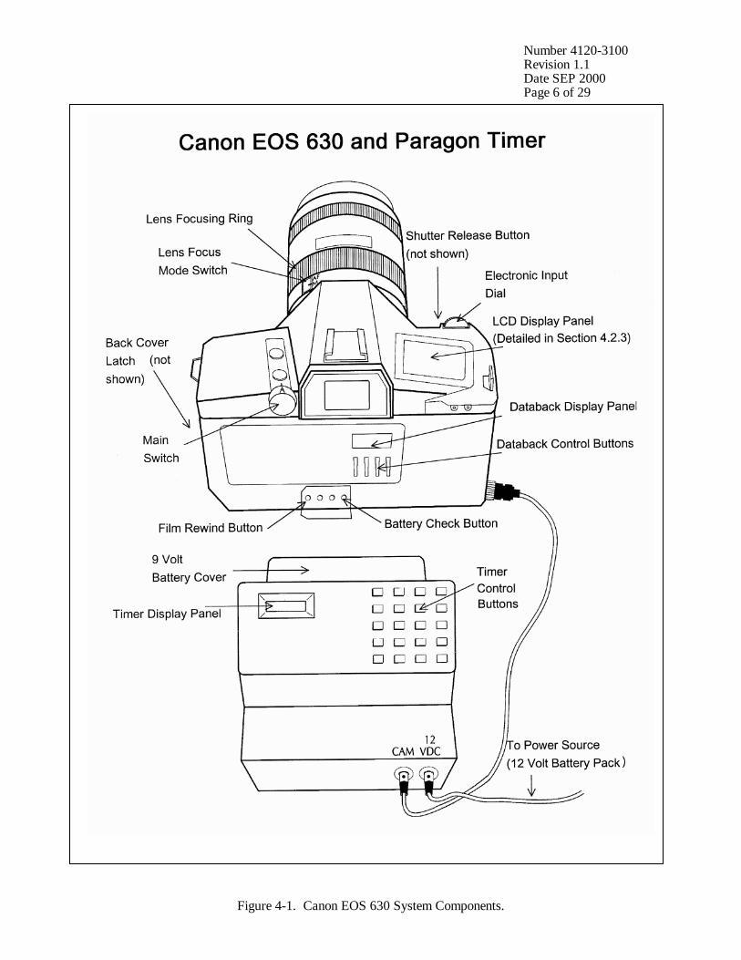
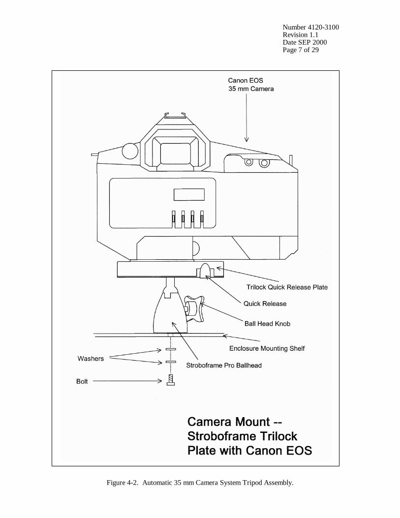
3.2 INVENTORY It is imperative that any capital instrumentation changes made as a result of routine maintenance be thoroughly documented. Specific model and serial numbers of the exchanged enclosure, camera body, lens, databack, and/or automatic timer should be documented for future reference by the data coordinator in the site-specific Quality Assurance Database and ARS Purchase Order/Inventory Database. Any on-site changes made should be documented by the site operator on a Visibility Monitoring Status/Assessment Sheet. Capital equipment exchange procedures are discussed in TI 4120-3300, Troubleshooting and Emergency Maintenance Procedures for 35 mm Automatic Camera System - Canon EOS 630. 4.0 METHODS This section includes two (2) major subsections: 4.1 Routine Servicing 4.2 Scheduled Maintenance Detailed procedures described in these subsections are summarized in Table 4-1. A variety of automatic camera monitoring configurations exist. Specific equipment servicing requirements for each site will vary with the system configuration. All procedures described in this TI refer to the Canon EOS 630 35 mm camera and Paragon EC72D automatic timer. Routine servicing procedures are summarized in the Automatic 35 mm Camera System User’s Manual for the Canon EOS 630 System, provided in the site operator’s manual. Detailed schematic diagrams of the Canon EOS 35 mm camera system and associated components are provided in Figures 4-1 through 4-3. The following manufacturers’ instruction booklets are provided for reference in the Site Operator’s Manual for Automatic Visibility Monitoring Camera Systems:
• Canon EOS 630 Part I
• Canon EOS 630 Part II
• Canon Quartz Date Back E
• Paragon EC72, EC72D, and EC72E Resolution of problems noted during routine servicing or scheduled maintenance can be more fully investigated by following the troubleshooting and emergency maintenance procedures defined in TI 4120-3300. 4.1 ROUTINE SERVICING Routine servicing schedules are based on the number of photographs taken each day. A common monitoring schedule includes taking three photographs a day at 0900, 1200, and 1500. Assuming this schedule, site operators service the camera approximately every 10 days. Alternate monitoring schedules are discussed in Section 4.2.3. Supplemental film and backup batteries should be on hand whenever the site is visited, this will minimize servicing time and data loss should a problem occur or be detected during servicing.
Number 4120-3100 Revision 1.1 Date SEP 2000 Page 5 of 29
Table 4-1
Automatic Camera System Field Quality Control Procedures
Regular Maintenance performed at each film change: • Inspect overall system and clean shelter window. • Remove camera. • Verify that film advanced and settings are correct. • Rewind and remove film (complete film canister label). • Load new film (complete film canister label). • Inspect and clean camera lens. • Check system batteries. • Check camera and databack settings. • Check timer settings. • Photograph film documentation board. • Replace and align camera. • Verify system operation. • Complete Visibility Monitoring Status/Assessment Sheets: - Document any equipment or monitoring discrepancies found. - Document all servicing or maintenance actions performed. - Describe weather conditions. - Describe visibility conditions. • Close and lock camera enclosure. • Mail film and the white copy of the completed Visibility Monitoring Status/Assessment Sheet
to ARS. Scheduled Maintenance performed as scheduled or as required: • Change 35 mm databack batteries annually. • Change 35 mm camera batteries every 6 months. • Change 35 mm timer batteries every 6 months.
Number 4120-3100 Revision 1.1 Date SEP 2000 Page 6 of 29
Figure 4-1. Canon EOS 630 System Components.
Number 4120-3100 Revision 1.1 Date SEP 2000 Page 7 of 29
Figure 4-2. Automatic 35 mm Camera System Tripod Assembly.

Number 4120-3100 Revision 1.1 Date SEP 2000 Page 8 of 29
Figure 4-3. Automatic 35 mm Camera System Enclosure.
Number 4120-3100 Revision 1.1 Date SEP 2000 Page 9 of 29
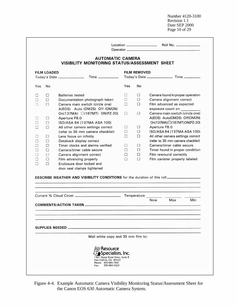
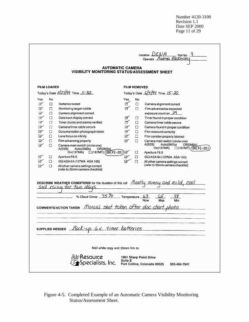
During each routine site visit, the operator will thoroughly document all pertinent data collection information, any maintenance performed, and note any equipment or monitoring discrepancies found on the Visibility Monitoring Status/Assessment Sheet (Figure 4-4). The site operator must complete all applicable portions of this sheet and mail the white original to the data coordinator with each roll of film. A completed example status/assessment sheet is provided in Figure 4-5. Blank status/assessment sheets are provided in the site operator’s manual. The following subsections detail how to complete the status/assessment sheet. 4.1.1 Status/Assessment Sheet General Information The following general information appears on the Visibility Monitoring Status/Assessment Sheet. LOCATION Either the full site location name or the four-letter site
abbreviation.
ROLL NO. The consecutive site roll number of the film used to document the monitoring period.
OPERATOR(S) The full name of the site operator(s).
DATE AND TIME The standard calendar date and local time when the film was loaded and when the film was removed.
WEATHER CONDITIONS At the time of film removal, describe recent and current weather conditions that may be helpful in interpreting the photographic data. Such conditions may include, but are not limited to: • Temperature extremes
• Percent cloud cover currently observed
• Severe weather (lightning, hail, high winds, etc.)
• Passing storm fronts
• Precipitation
• Stagnant air masses
• Fog
VISIBILITY CONDITIONS Describe recent and current visibility conditions that may be useful in verifying qualitative photographic observations. Such conditions may include, but are not limited to: • Extremely clean
• Regional haze
• Layered haze
Number 4120-3100 Revision 1.1 Date SEP 2000 Page 10 of 29
Figure 4-4. Example Automatic Camera Visibility Monitoring Status/Assessment Sheet for the Canon EOS 630 Automatic Camera System.
Number 4120-3100 Revision 1.1 Date SEP 2000 Page 11 of 29
Figure 4-5. Completed Example of an Automatic Camera Visibility Monitoring Status/Assessment Sheet.
Number 4120-3100 Revision 1.1 Date SEP 2000 Page 12 of 29
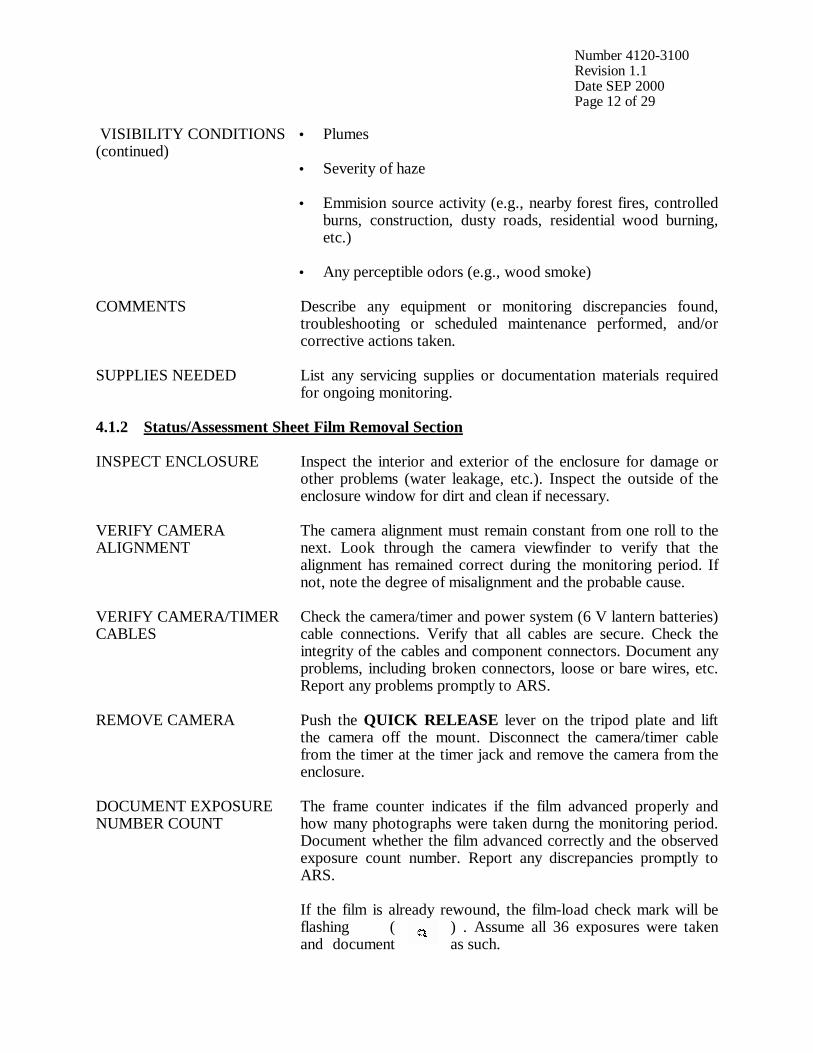
VISIBILITY CONDITIONS (continued)
• Plumes
• Severity of haze
• Emmision source activity (e.g., nearby forest fires, controlled burns, construction, dusty roads, residential wood burning, etc.)
• Any perceptible odors (e.g., wood smoke)
COMMENTS Describe any equipment or monitoring discrepancies found, troubleshooting or scheduled maintenance performed, and/or corrective actions taken.
SUPPLIES NEEDED List any servicing supplies or documentation materials required for ongoing monitoring.
4.1.2 Status/Assessment Sheet Film Removal Section INSPECT ENCLOSURE Inspect the interior and exterior of the enclosure for damage or
other problems (water leakage, etc.). Inspect the outside of the enclosure window for dirt and clean if necessary.
VERIFY CAMERA ALIGNMENT
The camera alignment must remain constant from one roll to the next. Look through the camera viewfinder to verify that the alignment has remained correct during the monitoring period. If not, note the degree of misalignment and the probable cause.
VERIFY CAMERA/TIMER CABLES
Check the camera/timer and power system (6 V lantern batteries) cable connections. Verify that all cables are secure. Check the integrity of the cables and component connectors. Document any problems, including broken connectors, loose or bare wires, etc. Report any problems promptly to ARS.
REMOVE CAMERA Push the QUICK RELEASE lever on the tripod plate and lift the camera off the mount. Disconnect the camera/timer cable from the timer at the timer jack and remove the camera from the enclosure.
DOCUMENT EXPOSURE NUMBER COUNT
The frame counter indicates if the film advanced properly and how many photographs were taken durng the monitoring period. Document whether the film advanced correctly and the observed exposure count number. Report any discrepancies promptly to ARS. If the film is already rewound, the film-load check mark will be flashing ( ) . Assume all 36 exposures were taken and document as such.
Number 4120-3100 Revision 1.1 Date SEP 2000 Page 13 of 29
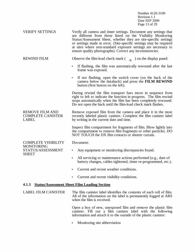
VERIFY SETTINGS Verify all camera and timer settings. Document any settings that are different from those listed on the Visibility Monitoring Status/Assessment Sheet, whether they are site-specific settings or settings made in error. (Site-specific settings may be required at sites where non-standard exposure settings are necessary to ensure quality photographs). Correct any inconsistencies.
REWIND FILM Observe the film-load check mark ( ) on the display panel: • If flashing, the film was automatically rewound after the last
frame was exposed.
• If not flashing, open the switch cover (on the back of the camera below the databack) and press the FILM REWIND button (first button on the left).
During rewind the film transport bars move in sequence from right to left to indicate the function in progress. The film rewind stops automatically when the film has been completely rewound. Do not open the back until the film-load check mark flashes.
REMOVE FILM AND COMPLETE CANISTER LABEL
Remove exposed film from the camera and place it in the most recently labeled plastic canister. Complete the film canister label by writing in the current date and time. Inspect film compartment for fragments of film. Blow lightly into the compartment to remove film fragments or other particles. DO NOT TOUCH the DX film contacts or shutter curtain.
COMPLETE VISIBILITY MONITORING STATUS/ASSESSMENT SHEET
Document: • Any equipment or monitoring discrepancies found.
• All servicing or maintenance actions performed (e.g., date of battery changes, cables tightened, timer re-programmed, etc.). • Current and recent weather conditions.
• Current and recent visibility conditions.
4.1.3 Status/Assessment Sheet Film Loading Section LABEL FILM CANISTER
The film canister label identifies the contents of each roll of film. All of the information on the label is permanently logged at ARS when the film is received. Open a box of new, unexposed film and remove the plastic film canister. Fill out a film canister label with the following information and attach it to the outside of the plastic canister: • Monitoring site abbreviation
Number 4120-3100 Revision 1.1 Date SEP 2000 Page 14 of 29
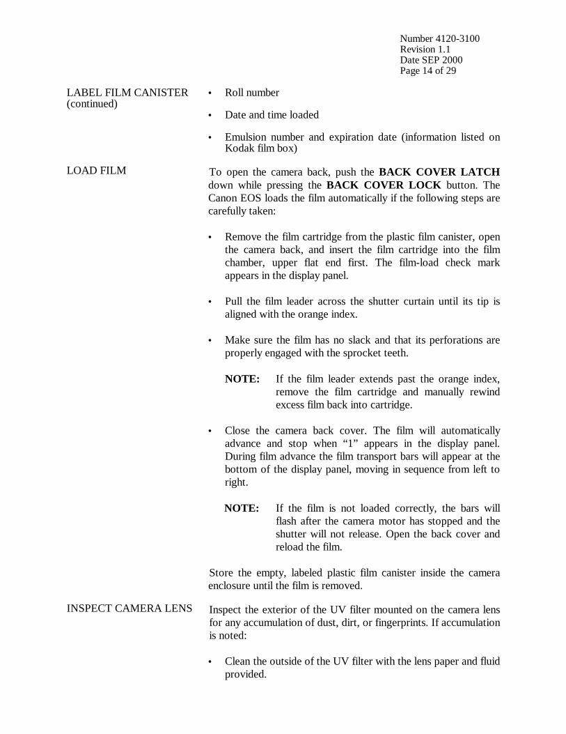
LABEL FILM CANISTER (continued)
• Roll number • Date and time loaded • Emulsion number and expiration date (information listed on
Kodak film box)
LOAD FILM To open the camera back, push the BACK COVER LATCH down while pressing the BACK COVER LOCK button. The Canon EOS loads the film automatically if the following steps are carefully taken: • Remove the film cartridge from the plastic film canister, open
the camera back, and insert the film cartridge into the film chamber, upper flat end first. The film-load check mark appears in the display panel.
• Pull the film leader across the shutter curtain until its tip is aligned with the orange index.
• Make sure the film has no slack and that its perforations are properly engaged with the sprocket teeth.
NOTE: If the film leader extends past the orange index, remove the film cartridge and manually rewind excess film back into cartridge. • Close the camera back cover. The film will automatically
advance and stop when “1” appears in the display panel. During film advance the film transport bars will appear at the bottom of the display panel, moving in sequence from left to right.
NOTE: If the film is not loaded correctly, the bars will flash after the camera motor has stopped and the shutter will not release. Open the back cover and reload the film. Store the empty, labeled plastic film canister inside the camera enclosure until the film is removed.
INSPECT CAMERA LENS
Inspect the exterior of the UV filter mounted on the camera lens for any accumulation of dust, dirt, or fingerprints. If accumulation is noted: • Clean the outside of the UV filter with the lens paper and fluid
provided.
Number 4120-3100 Revision 1.1 Date SEP 2000 Page 15 of 29
INSPECT CAMERA LENS (continued)
• If necessary, unscrew the UV filter and clean the lens and inside surface of the UV filter. Do not remove the lens from the camera body or attempt to clean inner surface of the lens.
• Use lens paper and fluid to clean the viewfinder eyepiece when necessary.
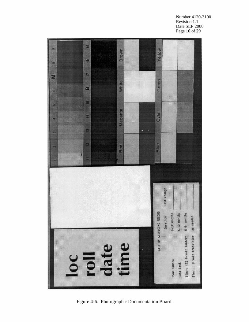
PHOTOGRAPH DOCUMENTATION BOARD
The first exposure on every roll must be of the documentation board which contains the gray scale, color chart, battery servicing record, and pertinent data collection information (Figure 4-6). • Write the following on the note pad provided: - Monitoring site name or abbreviation - Roll number - Date and time • Adjust your position and turn the focus ring to achieve a
close-up, sharply focused photograph.
• Press the SHUTTER BUTTON. Verify that the film counter has incremented one frame.
• Reset the focus ring to infinity. The documentation chart should be evenly lit for the photograph. The board is mounted to the enclosed door with Velcro tabs and may be temporarily removed if proper lighting conditions are not possible in its normal position. You may have to shift your position slightly to find a spot where there is no glare from the sun on the board.
CHECK CAMERA BATTERY
Open the switch cover (on the back of the camera below the databack) and press the BATTERY CHECK button (the button at the farthest right). While pressing the button, observe the display panel. A “bc” appears in the display and the level of battery power is indicated by: • three bars - battery power sufficient
• two bars - low (have a new battery on hand)
• one flashing bar - very low (replace with a new battery) • blank display - drained (replace with a new battery)
Number 4120-3100 Revision 1.1 Date SEP 2000 Page 16 of 29
Figure 4-6. Photographic Documentation Board.
Number 4120-3100 Revision 1.1 Date SEP 2000 Page 17 of 29
CHECK CAMERA BATTERY (continued)
If required, change the camera 6 V lithium battery and retest the system. Document all battery changes on the Visibility Monitoring Status/Assessment Sheet and “battery servicing record” portion of the documentation chart. Report any problems promptly to ARS. Camera battery change procedures are described further in Section 4.2.2.
CHECK CAMERA SETTINGS
Verify and change, if necessary, all camera settings for correct automatic operation. Standard settings for the Canon EOS 630 are: Main Switch A Aperture f8.0 ISO/ASA 64 Exposure Compensation 0 (Zero) Program Mode Selection AV Drive Mode Selector S (single) Lens Focus Mode M (manual) Lighting conditions of the target or vista may require site-specific exposure settings. Setting changes directed by ARS are documented on the enclosure door and in the Automatic 35 mm Camera System User’s Manual provided in the site operator’s manual. Document any settings that are different from those listed above on each Visibility Monitoring Status/Assessment Sheet.
CHECK DATABACK SETTING AND BATTERIES
The databack should be in the “day-time” mode displaying the current day of the month and current time. If the word “BATTERY” is displayed or if the display is blank, the databack battery is drained. Replace the battery only when the film is not loaded. Document all battery changes on the Visibility Monitoring Status/Assessment Sheet and “battery servicing record” portion of the documentation chart. Reset the databack for the current date and time. Databack setting and programming instructions, as well as battery change procedures are described further in Section 4.2.
CHECK TIMER SETTINGS
Review timer display: • The Paragon EC72D should be in the “RUN” mode
displaying the local time and day-of-week, and the colon should be flashing.
• If the display is incorrect press RUN on the display panel to verify that the timer is in the “RUN” mode. If the time, date, or display is still incorrect, reset the timer.
• If the timer display is blank, the timer battery wiring may be
incorrect or the battery power may be insufficient.
Number 4120-3100 Revision 1.1 Date SEP 2000 Page 18 of 29
CHECK TIMER SETTINGS (continued)
Review the programmed timer events: • Press PRG then C1 to select Channel 1 for review.
• Press E repeatedly to review each event. In normal operation,
Event 1 (E:01) is 0900, Event 2 (E:02) is 1200, and Event 3 (E:03) is 1500. The remaining events are not programmed.
If events are incorrect, reprogram the timer clock and timer events. Timer setting and programming instructions are provided in Section 4.2.3. Press RUN when finished reviewing or changing events to return the timer to the “RUN” mode. NOTE: If a photograph was scheduled to occur while you were reviewing or programming information, the photograph was not taken.
REPLACE AND ALIGN CAMERA
It is important for the alignment to be consistent from one roll to the next. • Mount the camera on the tripod plate.
• Securely reconnect the camera/timer cable to the timer at the
timer jack.
• Look through the viewfinder and align the camera on the vista to be photographed.
• Verify that the alignment matches the previous alignment, the horizon is level, the enclosure port does not appear in the frame, and the lens focus is on infinity. (A 3” x 5” site alignment photograph is provided in the camera enclosure for reference).
• Firmly tighten all levers on the tripod head and recheck the alignment.
If weather conditions obscure the target area, use foreground features to judge alignment. Visit the site again when the weather clears to recheck the alignment.
VERIFY CAMERA/TIMER CABLES AND FILM ADVANCE
Verify the camera/timer and power system (6 V lantern batteries) cable connections. Test the timer and battery cable connections: • The timer must be in the “RUN” mode, with the time and
day-of-week displayed and colon flashing. • Press C1; the camera should fire. The timer automatically
returns to the “RUN” mode.
Number 4120-3100 Revision 1.1 Date SEP 2000 Page 19 of 29
VERIFY CAMERA/TIMER CABLES AND FILM ADVANCE (continued)
If the camera does not fire, the camera/timer wiring is incorrect or the battery power to the timer is insufficient. Test the camera/timer cable connection: • Gently shake the camera/timer cable leading into the camera
remote jack. If the camera fires, an electrical short may exist in a portion of the cable jack(s).
• Observe the camera display panel. The display should not illuminate for more than 6 seconds. If the display continues to illuminate beyond 6 seconds, an electrical short may exist in a portion of the cable jack.
Document any discrepancies and/or corrective actions taken. Report any problems promptly to ARS.
DOCUMENT FINDINGS AND ACTIONS PERFORMED
Document any servicing or maintenance actions performed during the film loading process. Place the completed Visibility Monitoring Status/Assessment Sheet (yellow copy) in the Site Operator’s Manual for Automatic Visibility Monitoring Camera Systems.
CLOSE AND SECURE ENCLOSURE
Place the Site Operator’s Manual for Automatic Visibility Monitoring Camera Systems inside the camera enclosure for future reference. Close and lock the camera enclosure door. Tighten all door seal clamps and padlock the enclosure door hasp.
4.1.4 Mailing the Film and Completed Status/Assessment Sheet Place the original (white) copy of the Visibility Monitoring Status/Assessment Sheet and corresponding roll of film in a padded mailing envelope. Mail both the film and the Visibility Monitoring Status/Assessment Sheet immediately to: Air Resource Specialists, Inc. 1901 Sharp Point Drive, Suite E Fort Collins, CO 80525 Attention: Photographic Data Coordinator Call ARS immediately if any inconsistencies were noted or if any questions arise. Many problems can be resolved through telephone consultation. ARS may be reached at the following telephone numbers: Telephone: 970/484-7941 Fax: 970/484-3423 Detailed troubleshooting procedures to assist with telephone-directed problem resolution are presented in TI 4120-3300, Troubleshooting and Emergency Maintenance Procedures for 35 mm Automatic Camera System - Canon EOS 630.
Number 4120-3100 Revision 1.1 Date SEP 2000 Page 20 of 29
4.2 SCHEDULED MAINTENANCE Proper film storage and periodic preventive maintenance will help to ensure consistent, high quality data collection. Preventive maintenance servicing visits are performed as scheduled or required by the data coordinator. Scheduled maintenance normally consists of:
• Camera battery changes (every six months)
• Databack battery changes (annually)
• Timer battery changes (every six months) Replacement camera and timer batteries are provided by ARS with each film shipment (every six months). Replacement databack batteries are provided annually. Additional batteries will be provided as needed or as requested by the site operator. Test all batteries with a voltmeter before placing them in the system component. Verify all timer or camera battery malfunctions by testing removed component batteries with a voltmeter. Additional servicing tasks identified by the data coordinator may include:
• Camera, databack, and timer configuration checks or changes
• Camera alignment changes
• Revision of data collection procedures All scheduled maintenance requested by the data coordinator or performed by the site operator must be thoroughly documented on the Visibility Monitoring Status/Assessment Sheet and in the site-specific Quality Assurance Database. Any equipment malfunctions or data collection discrepancies observed during a scheduled maintenance visit should be reported to ARS immediately. The following subsections further describe proper methods for film storage, scheduled maintenance procedures, and corresponding servicing documentation. Troubleshooting and emergency maintenance procedures for the Canon EOS 630 are provided in TI 4120-3300. 4.2.1 Film and Film Storage Only Kodachrome 64 slide film provided by ARS should be loaded into the visibility monitoring camera unless otherwise directed. Each roll of film has an emulsion number and expiration date. This information must be documented on the canister label of each exposed film roll (see Section 4.1.3).
Number 4120-3100 Revision 1.1 Date SEP 2000 Page 21 of 29
Photographic film is sensitive to heat and moisture. These elements can affect the film, altering both the processed photographs and the data analysis. For example, film subjected to heat often has a pink or purple cast while film subjected to moisture does not process consistently. To ensure proper film storage, keep the film inside a Ziploc bag with desiccant and place the bag inside the clearly labeled film storage box. The box should be stored in a freezer, refrigerator, or cool (less than 70°F), dry location. If stored in a freezer, allow film to thaw at room temperature for at least two hours before loading it in the camera. 4.2.2 Changing System Batteries CAMERA BATTERY CHANGE
The Canon EOS 630 camera runs on one 6 V lithium battery pack. This battery should be replaced every six months or as directed by the data coordinator. • Remove the grip by loosening the screw on the right side of
the camera with a coin or similar object.
• Push the orange lever in the battery compartment upward to release the used battery. Tilt the camera to allow the used battery to slide out of the compartment. Measure and record the voltage of the used battery.
• Remove the new battery from its packaging and test and record the voltage. The new battery should measure approximately 6 volts.
• Insert the new battery end first and lock it in place with the orange lever.
• Replace the grip securely and check the battery as described in Section 4.1.3.
DATABACK BATTERY CHANGE
The Canon Quartz Date Back E runs on one 3 V coin-shaped lithium battery.The databack battery should be replaced annually, or as required by the data coordinator. Be sure to replace the battery only when film is not loaded. • Open the camera back. The battery compartment is located on
the inside of the databack opposite the hinge. To open the compartment, turn the screw counterclockwise using a small Phillips-head screwdriver.
• Insert the screwdriver tip into the chamber and then gently push the used battery. It will pop up and can then be removed. Measure and record the voltage of the used battery.
• Remove the new battery from its packaging and test and
record the voltage. The new battery should measure approximately 3 volts.
Number 4120-3100 Revision 1.1 Date SEP 2000 Page 22 of 29
DATABACK BATTERY CHANGE (continued)
• Wait 15 seconds after removing the used battery and then load the new battery with the “+” side facing up.
• To load the new battery, first insert one side into the chamber and then press it to the left with your finger until it will go no further.
• Slide the battery slightly to the right, lock it into place and replace the cover; tighten the screw securely.
• Check the display and reset the databack for the current date and time as described in Section 4.1.3.
TIMER BATTERY VERIFICATION AND CHANGES
The Paragon EC72D timer runs on two 6 V lantern batteries. Both 6 V lantern batteries should be replaced biannually or as directed by the data coordinator. To test the main power source (two 6 volt batteries): • The timer must be in “RUN” mode, with the time and day
displayed and colon flashing.
• Press C1; the camera should fire. The timer automatically returns to the “RUN” mode.
• If the camera does not fire, the camera/timer wiring is
incorrect or the battery power to the timer is insufficient. Test and record the voltage of the used batteries. Camera/timer wiring verification procedures are described in Section 4.1.3.
To change the 6 volt batteries (Figure 4-7): • Remove battery cover (located above timer control panel) by
pressing sides together and pulling left or right.
• Snap a 9 V battery into the battery clip.
• Temporarily attach a 9 V battery to the back of the timer (see Figure 4-1). The 9 V will help the timer hold its programmed memory while you change the main power batteries.
• Disconnect all wires from the used batteries.
• Place the new 6 V batteries together at opposite polarity (in series).
• Connect the two 6 V batteries at one end.
• Connect the opposite terminals to the cable from the timer.
• Disconnect the 9 V battery and replace the battery cover.
Number 4120-3100 Revision 1.1 Date SEP 2000 Page 23 of 29
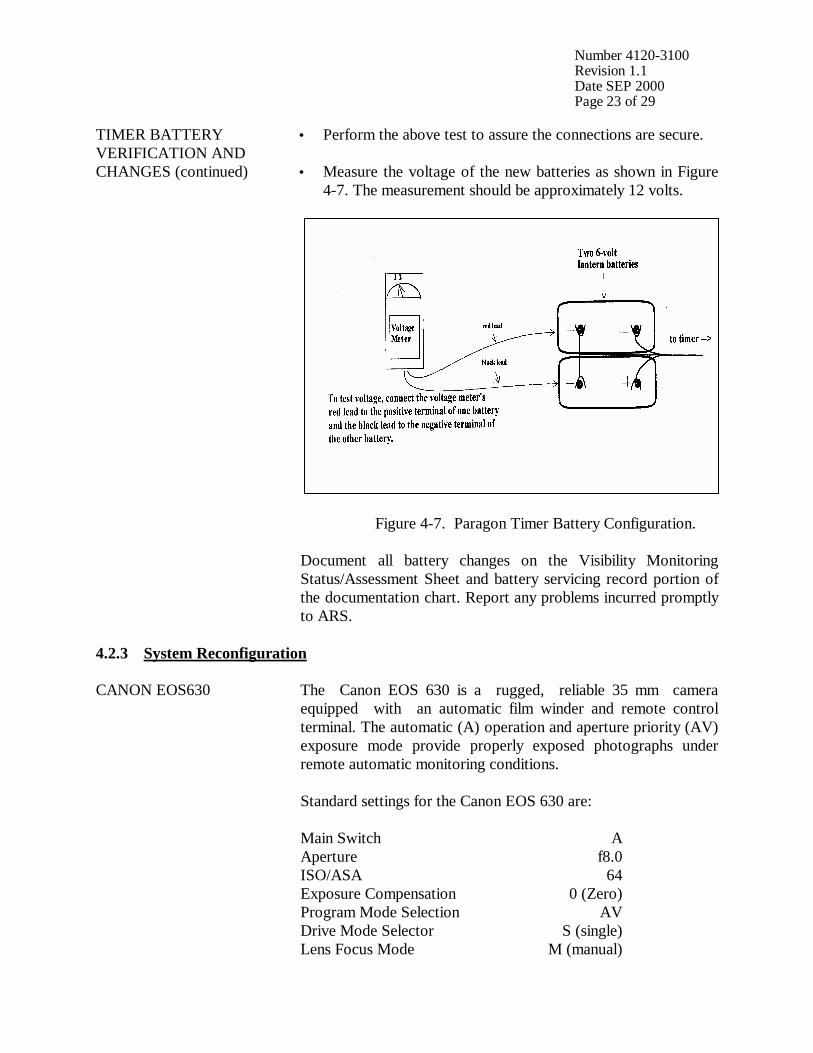
TIMER BATTERY VERIFICATION AND CHANGES (continued)
• Perform the above test to assure the connections are secure. • Measure the voltage of the new batteries as shown in Figure
4-7. The measurement should be approximately 12 volts. Figure 4-7. Paragon Timer Battery Configuration. Document all battery changes on the Visibility Monitoring Status/Assessment Sheet and battery servicing record portion of the documentation chart. Report any problems incurred promptly to ARS.
4.2.3 System Reconfiguration CANON EOS630 The Canon EOS 630 is a rugged, reliable 35 mm camera
equipped with an automatic film winder and remote control terminal. The automatic (A) operation and aperture priority (AV) exposure mode provide properly exposed photographs under remote automatic monitoring conditions. Standard settings for the Canon EOS 630 are: Main Switch A Aperture f8.0 ISO/ASA 64 Exposure Compensation 0 (Zero) Program Mode Selection AV Drive Mode Selector S (single) Lens Focus Mode M (manual)
Number 4120-3100 Revision 1.1 Date SEP 2000 Page 24 of 29
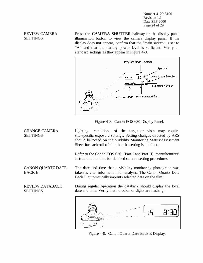
REVIEW CAMERA SETTINGS
Press the CAMERA SHUTTER halfway or the display panel illumination button to view the camera display panel. If the display does not appear, confirm that the “main switch” is set to “A” and that the battery power level is sufficient. Verify all standard settings as they appear in Figure 4-8. Figure 4-8. Canon EOS 630 Display Panel.
CHANGE CAMERA SETTINGS
Lighting conditions of the target or vista may require site-specific exposure settings. Setting changes directed by ARS should be noted on the Visibility Monitoring Status/Assessment Sheet for each roll of film that the setting is in effect. Refer to the Canon EOS 630 (Part I and Part II) manufacturers’ instruction booklets for detailed camera setting procedures.
CANON QUARTZ DATE BACK E
The date and time that a visibility monitoring photograph was taken is vital information for analysis. The Canon Quartz Date Back E automatically imprints selected data on the film.
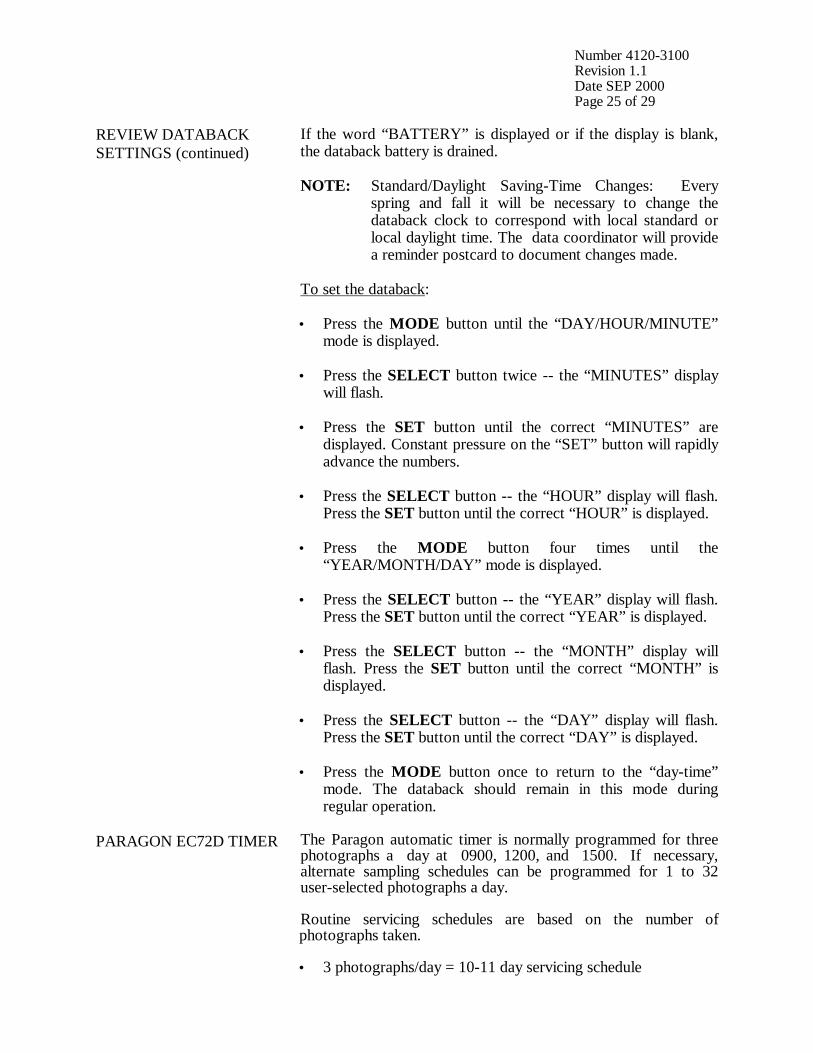
REVIEW DATABACK SETTINGS
During regular operation the databack should display the local date and time. Verify that no colon or digits are flashing.
Figure 4-9. Canon Quartz Date Back E Display.
Number 4120-3100 Revision 1.1 Date SEP 2000 Page 25 of 29
REVIEW DATABACK SETTINGS (continued)
If the word “BATTERY” is displayed or if the display is blank, the databack battery is drained. NOTE: Standard/Daylight Saving-Time Changes: Every spring and fall it will be necessary to change the databack clock to correspond with local standard or local daylight time. The data coordinator will provide a reminder postcard to document changes made. To set the databack: • Press the MODE button until the “DAY/HOUR/MINUTE”
mode is displayed.
• Press the SELECT button twice -- the “MINUTES” display will flash.
• Press the SET button until the correct “MINUTES” are displayed. Constant pressure on the “SET” button will rapidly advance the numbers.
• Press the SELECT button -- the “HOUR” display will flash. Press the SET button until the correct “HOUR” is displayed.
• Press the MODE button four times until the “YEAR/MONTH/DAY” mode is displayed.
• Press the SELECT button -- the “YEAR” display will flash. Press the SET button until the correct “YEAR” is displayed.
• Press the SELECT button -- the “MONTH” display will flash. Press the SET button until the correct “MONTH” is displayed.
• Press the SELECT button -- the “DAY” display will flash. Press the SET button until the correct “DAY” is displayed.
• Press the MODE button once to return to the “day-time” mode. The databack should remain in this mode during regular operation.
PARAGON EC72D TIMER
The Paragon automatic timer is normally programmed for three photographs a day at 0900, 1200, and 1500. If necessary, alternate sampling schedules can be programmed for 1 to 32 user-selected photographs a day. Routine servicing schedules are based on the number of photographs taken. • 3 photographs/day = 10-11 day servicing schedule
Number 4120-3100 Revision 1.1 Date SEP 2000 Page 26 of 29
PARAGON EC72D TIMER (continued)
• 2 photographs/day = 15-17 day servicing schedule
• 1 photograph/day = 30-33 day servicing schedule. During regular operation the Paragon EC72D should be in the “RUN” mode displaying the local time and day-of-week (Sunday = 1; Saturday = 7) with the colon flashing.
SETTING THE PARAGON EC72D TIMER
To set the timer clock: Wire power (two 6 V lantern batteries) to timer. A “0:00 1” is displayed, with a colon and “1” flashing. Press CLK; the flashing stops. • Using the 24-hour clock format, press four keys for the
current time (e.g., 1015 = 10:15 a.m.). Press one key for the current date of the week; (1 = Sunday . . . 7 = Saturday). Press E to enter.
• “101” is displayed, indicating “January 1”. Press two keys for the current month and two keys for the current date (e.g., 0615 = June 15). Press E to enter.
• “84” is displayed, indicating “1984”. Press two keys for the current year (e.g., 90). Press E to enter. Control will automatically switch to the “RUN” mode. The time and day of week will be displayed with the colon flashing.
To program times for photographs to be taken: • Press PRG to enter “program” mode.
• Press C1 to select Channel 1 for programming; “E:01” (for
the first event) is displayed.
• Press four keys for the time the first photograph should be taken (e.g., 0900 for 9:00 a.m.). Press 0 to program the event to occur daily. Press E to enter the event into memory.
• The next event slot will be displayed (e.g., E:02). Repeat the step immediately above for each time of the day a photograph should be taken.
• Press RUN to return to “RUN” mode after all selected photograph times are programmed.
Procedures to review programmed timer events are provided in Section 4.1.3. NOTE: If more than 16 photographs per day are desired, Channel 2 may be used to program up to 16 additional events provided the Channel 2 output terminals have also been wired to the camera.
Number 4120-3100 Revision 1.1 Date SEP 2000 Page 27 of 29
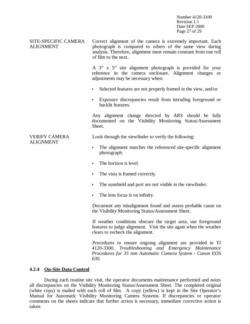
SITE-SPECIFIC CAMERA ALIGNMENT
Correct alignment of the camera is extremely important. Each photograph is compared to others of the same view during analysis. Therefore, alignment must remain constant from one roll of film to the next. A 3” x 5” site alignment photograph is provided for your reference in the camera enclosure. Alignment changes or adjustments may be necessary when: • Selected features are not properly framed in the view, and/or • Exposure discrepancies result from intruding foreground or
backlit features. Any alignment change directed by ARS should be fully documented on the Visibility Monitoring Status/Assessment Sheet.
VERIFY CAMERA ALIGNMENT
Look through the viewfinder to verify the following: • The alignment matches the referenced site-specific alignment
photograph.
• The horizon is level.
• The vista is framed correctly.
• The sunshield and port are not visible in the viewfinder.
• The lens focus is on infinity. Document any misalignment found and assess probable cause on the Visibility Monitoring Status/Assessment Sheet. If weather conditions obscure the target area, use foreground features to judge alignment. Visit the site again when the weather clears to recheck the alignment. Procedures to ensure ongoing alignment are provided in TI 4120-3300, Troubleshooting and Emergency Maintenance Procedures for 35 mm Automatic Camera System - Canon EOS 630.
4.2.4 On-Site Data Control During each routine site visit, the operator documents maintenance performed and notes all discrepancies on the Visibility Monitoring Status/Assessment Sheet. The completed original (white copy) is mailed with each roll of film. A copy (yellow) is kept in the Site Operator’s Manual for Automatic Visibility Monitoring Camera Systems. If discrepancies or operator comments on the sheets indicate that further action is necessary, immediate corrective action is taken.
Number 4120-3100 Revision 1.1 Date SEP 2000 Page 28 of 29
Throughout the monitoring effort, ARS and site operators maintain close personal communications. Operators are encouraged to call or notify ARS if they have questions or problems. Ongoing review of film and site operator documentation often initiates corrective actions. Common data collection problems identified include:
• Roll number discrepancies
• Missing or improperly exposed or focused documentation chart photographs
• Improper film loading or rewinding
• Late film changes
• Improper camera alignment
• Incorrect camera settings
• Weak or missing databack imprinting
• Incorrect timer settings
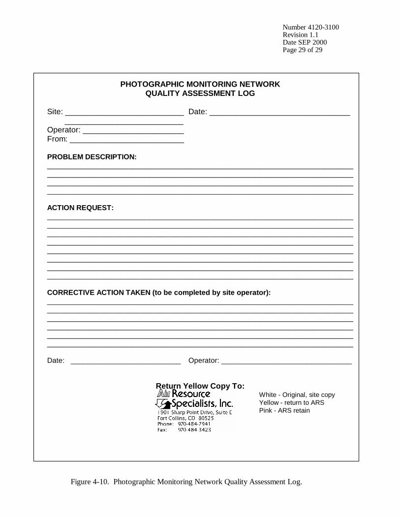
• Incomplete Visibility Monitoring Status/Assessment Sheet documentation All scheduled maintenance requested by the data coordinator or performed by the site operator must be thoroughly documented on the Visibility Monitoring Status/Assessment Sheet and in the site-specific Quality Assurance Database. If necessary, a Photographic Monitoring Network Quality Assessment Log (Figure 4-10) is mailed to the site to further document corrective actions taken. The site operator documents the date of correction and what was done, and returns a carbon copy of the log to ARS. Problems and equipment malfunctions requiring extensive troubleshooting and/or maintenance are fully described in TI 4120-3300.
Number 4120-3100 Revision 1.1 Date SEP 2000 Page 29 of 29
PHOTOGRAPHIC MONITORING NETWORK QUALITY ASSESSMENT LOG
Site: ___________________________ Date: ________________________________ ___________________________ Operator: _______________________ From: __________________________ PROBLEM DESCRIPTION: ______________________________________________________________________________________________________________________________________________________ ___________________________________________________________________________ ___________________________________________________________________________ ACTION REQUEST: ___________________________________________________________________________ ___________________________________________________________________________ ___________________________________________________________________________ ___________________________________________________________________________ ___________________________________________________________________________ ___________________________________________________________________________ ___________________________________________________________________________ ___________________________________________________________________________ CORRECTIVE ACTION TAKEN (to be completed by site operator): ___________________________________________________________________________ ___________________________________________________________________________ ___________________________________________________________________________ ___________________________________________________________________________ ___________________________________________________________________________ ___________________________________________________________________________ Date: ___________________________ Operator: ________________________________
Return Yellow Copy To: White - Original, site copy Yellow - return to ARS Pink - ARS retain Figure 4-10. Photographic Monitoring Network Quality Assessment Log.

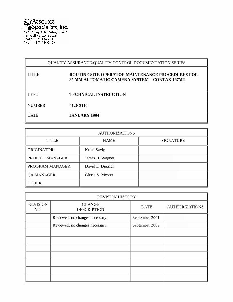
QUALITY ASSURANCE/QUALITY CONTROL DOCUMENTATION SERIES TITLE
ROUTINE SITE OPERATOR MAINTENANCE PROCEDURES FOR 35 MM AUTOMATIC CAMERA SYSTEM – CONTAX 167MT
TYPE
TECHNICAL INSTRUCTION
NUMBER
4120-3110
DATE
JANUARY 1994
AUTHORIZATIONS
TITLE NAME SIGNATURE
ORIGINATOR Kristi Savig
PROJECT MANAGER James H. Wagner
PROGRAM MANAGER David L. Dietrich
QA MANAGER Gloria S. Mercer
OTHER
REVISION HISTORY
REVISION NO.
CHANGE DESCRIPTION DATE AUTHORIZATIONS
Reviewed; no changes necessary. January 1995
Reviewed; no changes necessary. January 1996
1.0 Revise illustrations and forms. June 1996
Reviewed; no changes necessary. June 1997
Reviewed; no changes necessary. June 1998
Reviewed; no changes necessary. June 1999
Reviewed; no changes necessary. June 2000
1.1 Delete references to 9v battery in timer. September 2000
-- continued --
QUALITY ASSURANCE/QUALITY CONTROL DOCUMENTATION SERIES TITLE
ROUTINE SITE OPERATOR MAINTENANCE PROCEDURES FOR 35 MM AUTOMATIC CAMERA SYSTEM – CONTAX 167MT
TYPE
TECHNICAL INSTRUCTION
NUMBER
4120-3110
DATE
JANUARY 1994
AUTHORIZATIONS
TITLE NAME SIGNATURE
ORIGINATOR Kristi Savig
PROJECT MANAGER James H. Wagner
PROGRAM MANAGER David L. Dietrich
QA MANAGER Gloria S. Mercer
OTHER
REVISION HISTORY
REVISION NO.
CHANGE DESCRIPTION DATE AUTHORIZATIONS
Reviewed; no changes necessary. September 2001
Reviewed; no changes necessary. September 2002
Number 4120-3110 Revision 1.1 Date SEP 2000 Page i of ii
TABLE OF CONTENTS Section Page 1.0 PURPOSE AND APPLICABILITY 1 2.0 RESPONSIBILITIES 1 2.1 Project Manager 1 2.2 Field Specialist 1 2.3 Data Coordinator 2 2.4 Site Operator 2 3.0 REQUIRED EQUIPMENT AND MATERIALS 2 3.1 Site Visit Equipment 2 3.2 Inventory 4 4.0 METHODS 4 4.1 Routine Servicing 4 4.1.1 Status/Assessment Sheet General Information 9 4.1.2 Status/Assessment Sheet Film Removal Section 12 4.1.3 Status/Assessment Sheet Film Loading Section 13 4.1.4 Mailing the Film and Completed Status/Assessment Sheet 19 4.2 Scheduled Maintenance 19 4.2.1 Film and Film Storage 20 4.2.2 Changing System Batteries 20 4.2.3 System Reconfiguration 23 4.2.4 On-Site Data Control 27
LIST OF FIGURES Figure Page 4-1 Contax 167MT System Components 6 4-2 Automatic 35 mm Camera System Tripod Assembly 7 4-3 Automatic 35 mm Camera System Enclosure 8 4-4 Example Automatic Camera Visibility Monitoring Status/Assessment Sheet for the Contax 167MT Automatic Camera System 10
Number 4120-3110 Revision 1.1 Date SEP 2000 Page ii of ii
LIST OF FIGURES (CONTINUED.) Figure Page 4-5 Completed Example of an Automatic Camera Visibility Monitoring Status/Assessment Sheet 11 4-6 Photographic Documentation Board 15 4-7 Paragon Timer Battery Configuration 22 4-8 Contax 167MT Display 23 4-9 Contax Data Back D-7 Display 24 4-10 Photographic Monitoring Network Quality Assessment Log 28
LIST OF TABLES Table Page 4-1 Automatic Camera System Field Quality Control Procedures 5
Number 4120-3110 Revision 1.1 Date SEP 2000 Page 1 of 28
1.0 PURPOSE AND APPLICABILITY The purpose of routine site operator maintenance is to assure quality data capture and minimize data loss by performing and documenting scheduled operational checks and preventive maintenance. This technical instruction (TI) describes the steps of a routine site visit, scheduled maintenance, and on-site data control for the Contax 167MT 35 mm camera system. Routine servicing schedules are based on the number of photographs taken each day. Assuming a three-photograph per day schedule, site operators service the camera approximately every 10 days to change film, check the performance of the camera system, clean system components, and perform troubleshooting and/or emergency maintenance as required. Preventive maintenance site visits are performed every six months or as required by the data coordinator. The effective performance and documentation of each of these tasks is the key to quality data collection and minimal data loss. Site operators should be fully trained and supplied with a Site Operator’s Manual for Automatic Visibility Monitoring Camera Systems that contains detailed routine site operator maintenance and troubleshooting procedures for the specific camera monitoring system(s) located at the site. Additional manufacturer instruction booklets and a supply of Visibility Monitoring Status/Assessment Sheets are also provided. Close personal communications should be maintained between Air Resource Specialists, Inc. (ARS) and site operators throughout the monitoring effort. Operators are encouraged to call or notify ARS if they have any questions or problems. Many problems can be fully resolved over the telephone. 2.0 RESPONSIBILITIES 2.1 PROJECT MANAGER The project manager shall coordinate with the site operator, his/her supervisor, field specialist, and data coordinator concerning the schedule and requirements for routine maintenance. 2.2 FIELD SPECIALIST The field specialist shall:
• Coordinate with the project manager, the site operator, his/her supervisor, and data coordinator concerning the schedule and requirements for routine maintenance.
• Train the site operator in all phases of camera system maintenance.
• Provide technical support to the site operator via telephone to assure high quality site
visits.
• Resolve problems reported by the site operator.
• Document all technical support provided to the site operator.
Number 4120-3110 Revision 1.1 Date SEP 2000 Page 2 of 28
2.3 DATA COORDINATOR The data coordinator shall:
• Coordinate with the project manager, the site operator, his/her supervisor, and field specialist concerning the schedule and requirements for routine maintenance.
• Verify that scheduled visits are performed and notify the site operator if he/she fails to
make a scheduled visit.
• Review all site documentation completed by the site operator for accuracy and completeness. File all documentation and correspondence.
• Resolve problems reported by the site operator.
• Enter the results of all performed procedures into the site-specific Quality Assurance
Database.
• Supply the site operator with all necessary monitoring supplies.
• Coordinate the replacement and repair of all malfunctioning units.
• Document all capital instrumentation changes and maintain inventory records in the ARS Purchase Order/Inventory Database.
2.4 SITE OPERATOR The site operator shall:
• Coordinate with his/her supervisor, the project manager, data coordinator, and field specialist concerning the schedule and requirements for routine maintenance.
• Schedule regular site maintenance visits and perform all procedures described in this
TI.
• Thoroughly document all procedures on the Visibility Monitoring Status/Assessment Sheet; mail the white copy of the completed sheet to the data coordinator and maintain an on-site file of the yellow copy.
• Immediately report any noted inconsistencies to the data coordinator or field specialist.
3.0 REQUIRED EQUIPMENT AND MATERIALS 3.1 SITE VISIT EQUIPMENT Equipment and materials generally required to support a routine site visit or scheduled maintenance include:
• Medium and small flat-blade screwdriver
• Small Phillips-head screwdriver
• Medium adjustable wrench
Number 4120-3110 Revision 1.1 Date SEP 2000 Page 3 of 28
• Keys for enclosure and padlocks
• Voltmeter
• Backup camera, databack, and timer batteries:
- Contax 167MT: - four AAA alkaline batteries - Contax 167MT Data Back D-7: - two 3 V lithium batteries - Paragon EC72D: - two 6 V lantern batteries
• Watch
• Lens cleaner and lens paper
• Site Operator’s Manual for Automatic Visibility Monitoring Camera Systems containing:
- SOP 4120, Automatic Camera System Maintenance (IMPROVE Protocol) - TI 4120-3110, Routine Site Operator Maintenance Procedures for 35 mm
Automatic Camera System - Contax 167MT - TI 4120-3310, Troubleshooting and Emergency Maintenance Procedures for
35 mm Automatic Camera System - Contax 167MT - Automatic 35 mm Camera System User’s Manual - Manufacturers’ instruction booklets - Visibility Monitoring Status/Assessment Sheets - Film canister labels
• Pen or pencil
• Grease pencil
• Supplemental visibility monitoring film
• Padded mailing envelopes
Number 4120-3110 Revision 1.1 Date SEP 2000 Page 4 of 28
3.2 INVENTORY It is imperative that any capital instrumentation changes made as a result of routine maintenance be thoroughly documented. Specific model and serial numbers of the exchanged enclosure, camera body, lens, databack, and/or automatic timer should be documented for future reference by the data coordinator in the site-specific Quality Assurance Database and ARS Purchase Order/Inventory Database. Any on-site changes made should be documented by the site operator on a Visibility Monitoring Status/Assessment Sheet. Capital equipment exchange procedures are discussed in TI 4120-3310, Troubleshooting and Emergency Maintenance Procedures for 35 mm Automatic Camera System - Contax 167MT. 4.0 METHODS This section includes two (2) major subsections: 4.1 Routine Servicing 4.2 Scheduled Maintenance Detailed procedures described in these subsections are summarized in Table 4-1. A variety of automatic camera monitoring configurations exist. Specific equipment servicing requirements for each site will vary with the system configuration. All procedures described in this TI refer to the Contax 167MT 35 mm camera and Paragon EC72D automatic timer. Routine servicing procedures are summarized in the Automatic 35 mm Camera System User’s Manual for the Contax 167MT System, provided in the site operator’s manual. Detailed schematic diagrams of the Contax 167MT 35 mm camera system and associated components are provided in Figures 4-1 through 4-3. The following manufacturers’ instruction booklets are provided for reference in the Site Operator’s Manual for Automatic Visibility Monitoring Camera Systems:
• Contax 167MT
• Contax Data Back D-7
• Paragon EC72, EC72D, and EC72E Resolution of problems noted during routine servicing or scheduled maintenance can be more fully investigated by following the troubleshooting and emergency maintenance procedures defined in TI 4120-3310. 4.1 ROUTINE SERVICING Routine servicing schedules are based on the number of photographs taken each day. A common monitoring schedule includes taking three photographs a day at 0900, 1200, and 1500. Assuming this schedule, site operators service the camera approximately every 10 days. Alternate monitoring schedules are discussed in Section 4.2.3. Supplemental film and backup batteries should be on hand whenever the site is visited, this will minimize servicing time and data loss should a problem occur or be detected during servicing.

Number 4120-3110 Revision 1.1 Date SEP 2000 Page 5 of 28
Table 4-1
Automatic Camera System Field Quality Control Procedures
Regular Maintenance performed at each film change: • Inspect overall system and clean shelter window. • Remove camera. • Verify that film advanced and settings are correct. • Rewind and remove film (complete film canister label). • Load new film (complete film canister label). • Inspect and clean camera lens. • Check system batteries. • Check camera and databack settings. • Check timer settings. • Photograph film documentation board. • Replace and align camera. • Verify system operation. • Complete Visibility Monitoring Status/Assessment Sheets: - Document any equipment or monitoring discrepancies found. - Document all servicing or maintenance actions performed. - Describe weather conditions. - Describe visibility conditions. • Close and lock camera enclosure. • Mail film and the white copy of the completed Visibility Monitoring Status/Assessment
Sheet to ARS. Scheduled Maintenance performed as scheduled or as required: • Change 35 mm databack batteries annually. • Change 35 mm camera batteries every 6 months. • Change 35 mm timer batteries every 6 months.
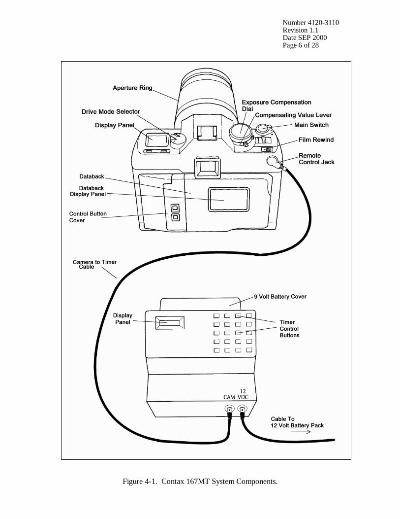
Number 4120-3110 Revision 1.1 Date SEP 2000 Page 6 of 28
Figure 4-1. Contax 167MT System Components.
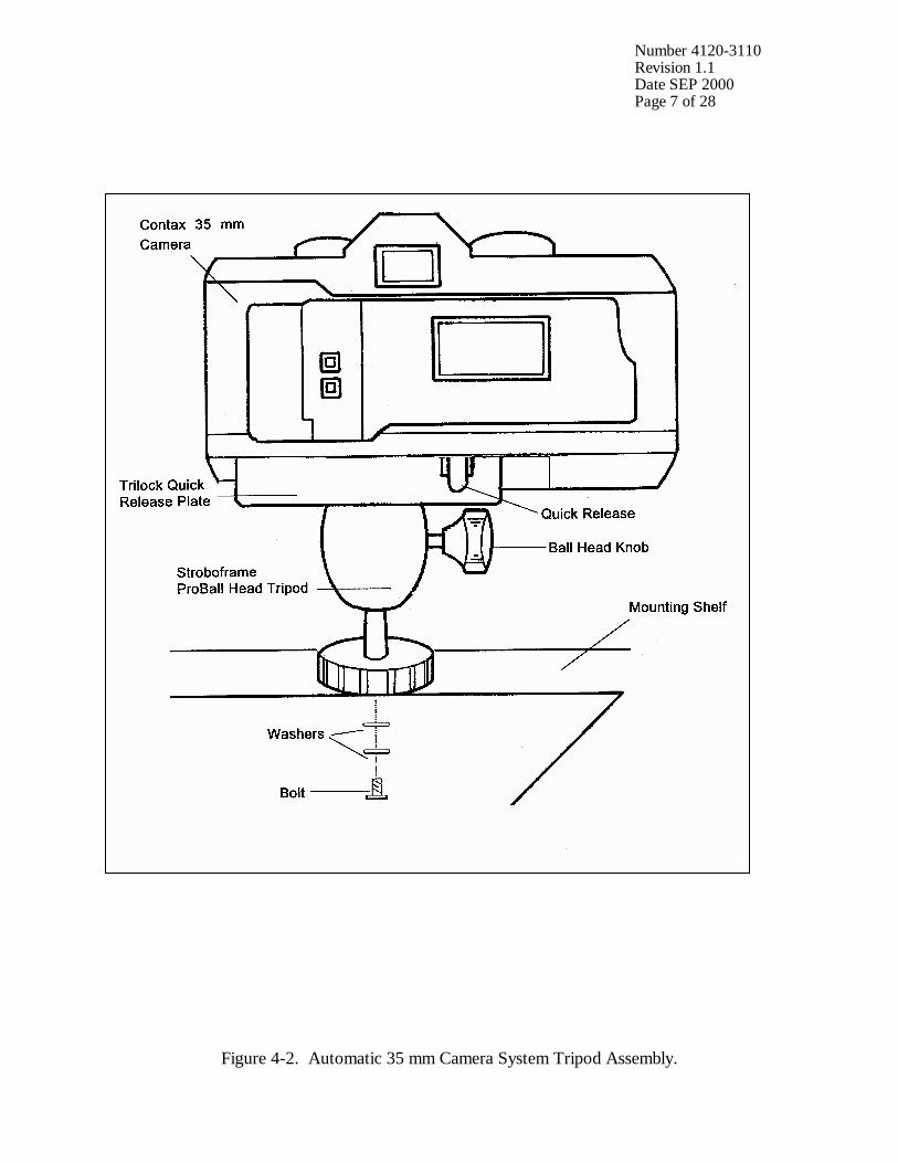
Number 4120-3110 Revision 1.1 Date SEP 2000 Page 7 of 28
Figure 4-2. Automatic 35 mm Camera System Tripod Assembly.
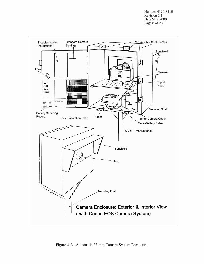
Number 4120-3110 Revision 1.1 Date SEP 2000 Page 8 of 28
Figure 4-3. Automatic 35 mm Camera System Enclosure.
Number 4120-3110 Revision 1.1 Date SEP 2000 Page 9 of 28
During each routine site visit, the operator will thoroughly document all pertinent data collection information, any maintenance performed, and note any equipment or monitoring discrepancies found on the Visibility Monitoring Status/Assessment Sheet (Figure 4-4). The site operator must complete all applicable portions of this sheet and mail the white original to the data coordinator with each roll of film. A completed example status/assessment sheet is provided in Figure 4-5. Blank status/assessment sheets are provided in the site operator’s manual. The following subsections detail how to complete the status/assessment sheet. 4.1.1 Status/Assessment Sheet General Information The following general information appears on the Visibility Monitoring Status/Assessment Sheet. LOCATION Either the full site location name or the four-letter site
abbreviation.
ROLL NO. The consecutive site roll number of the film used to document the monitoring period.
OPERATOR(S) The full name of the site operator(s).
DATE AND TIME The standard calendar date and local time when the film was loaded and when the film was removed.
WEATHER CONDITIONS At the time of film removal, describe recent and current weather conditions that may be helpful in interpreting the photographic data. Such conditions may include, but are not limited to: • Temperature extremes
• Percent cloud cover currently observed
• Severe weather (lightning, hail, high winds, etc.)
• Passing storm fronts
• Precipitation
• Stagnant air masses
• Fog
VISIBILITY CONDITIONS Describe recent and current visibility conditions that may be useful in verifying qualitative photographic observations. Such conditions may include, but are not limited to: • Extremely clean
• Regional haze
• Layered haze
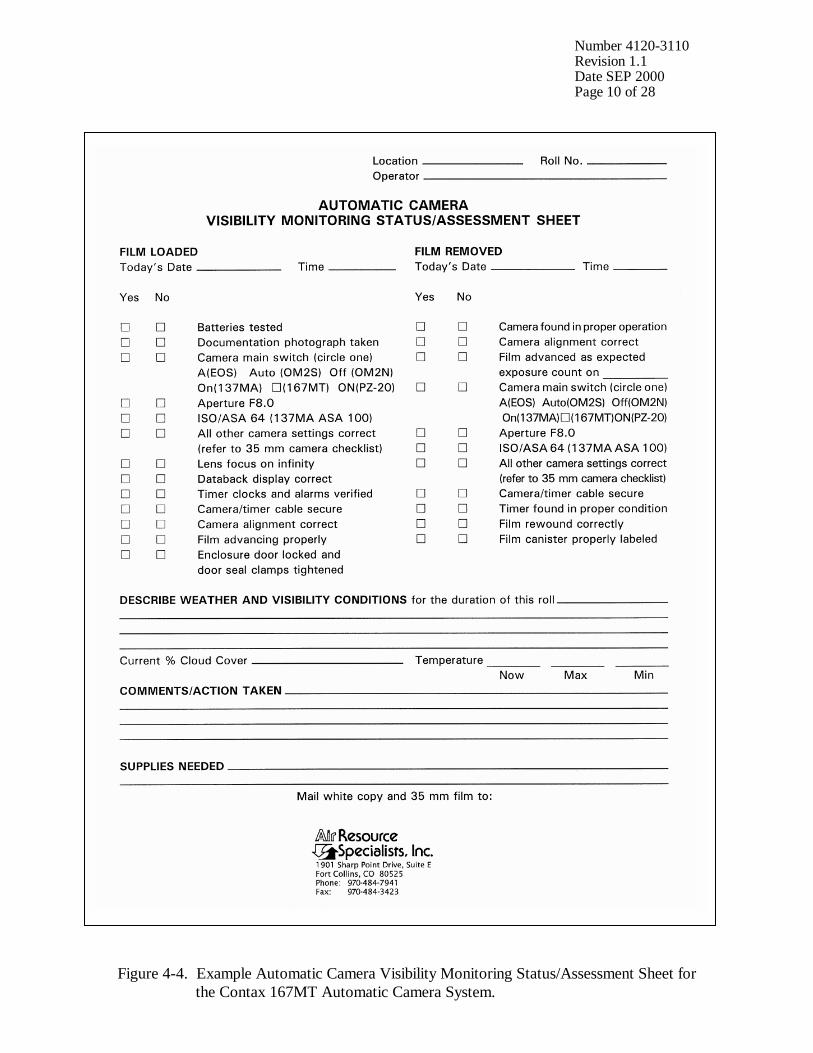
Number 4120-3110 Revision 1.1 Date SEP 2000 Page 10 of 28
Figure 4-4. Example Automatic Camera Visibility Monitoring Status/Assessment Sheet for the Contax 167MT Automatic Camera System.
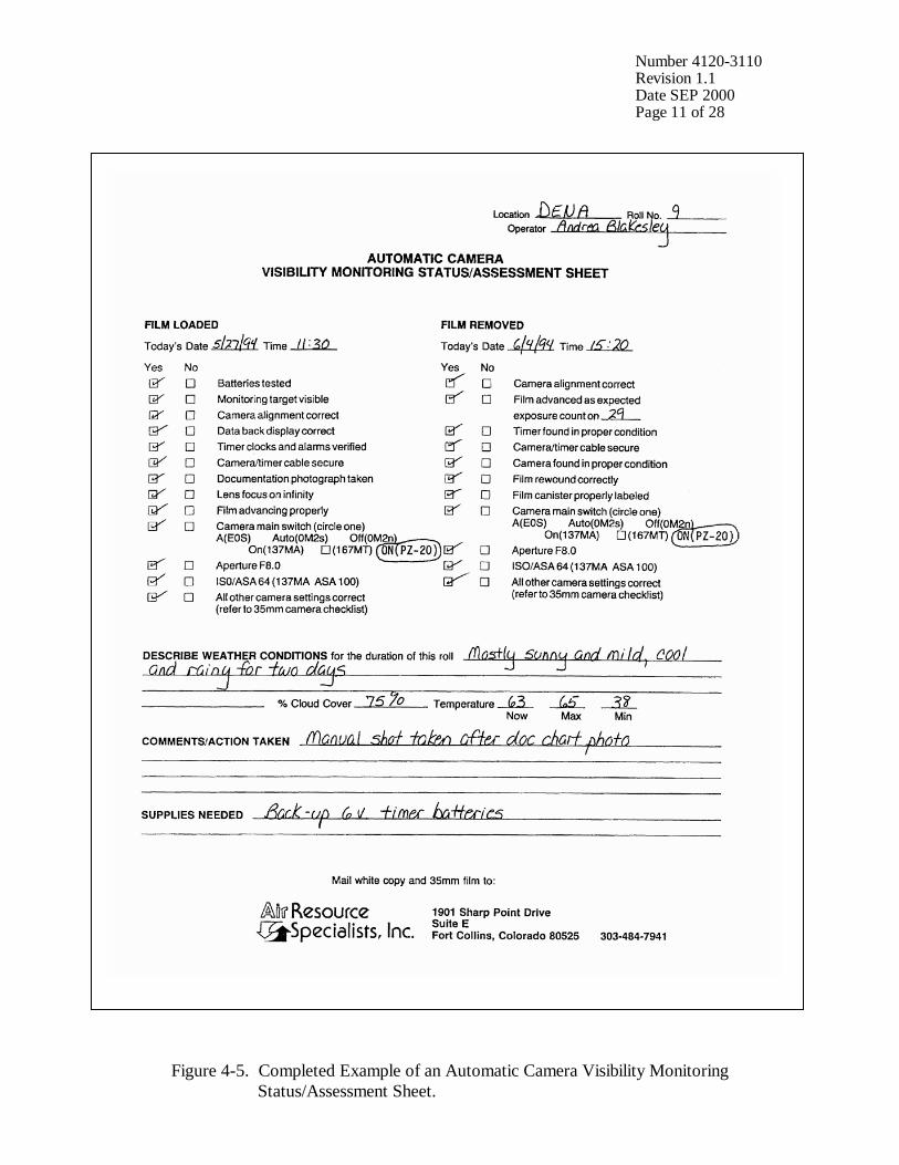
Number 4120-3110 Revision 1.1 Date SEP 2000 Page 11 of 28
Figure 4-5. Completed Example of an Automatic Camera Visibility Monitoring Status/Assessment Sheet.
Number 4120-3110 Revision 1.1 Date SEP 2000 Page 12 of 28
VISIBILITY CONDITIONS (continued)
• Plumes
• Severity of haze
• Emission source activity (e.g., nearby forest fires, controlled burns, construction, dusty roads, residential wood burning, etc.)
• Any perceptible odors (e.g., wood smoke)
COMMENTS Describe any equipment or monitoring discrepancies found, troubleshooting or scheduled maintenance performed, and/or corrective actions taken.
SUPPLIES NEEDED List any servicing supplies or documentation materials required for ongoing monitoring.
4.1.2 Status/Assessment Sheet Film Removal Section INSPECT ENCLOSURE Inspect the interior and exterior of the enclosure for damage or
other problems (water leakage, etc.). Inspect the outside of the enclosure window for dirt and clean if necessary.
VERIFY CAMERA ALIGNMENT
The camera alignment must remain constant from one roll to the next. Look through the camera viewfinder to verify that the alignment has remained correct during the monitoring period. If not, note the degree of misalignment and the probable cause.
VERIFY CAMERA/TIMER CABLES
Check the camera/timer and power system (6 V lantern batteries) cable connections. Verify that all cables are secure. Check the integrity of the cables and component connectors. Document any problems, including broken connectors, loose or bare wires, etc. Report any problems promptly to ARS.
REMOVE CAMERA Press and move the QUICK RELEASE lever to the “R” (release) position and lift the camera off the mount. Disconnect the camera/timer cable from the timer at the timer jack and remove the camera from the enclosure.
DOCUMENT EXPOSURE NUMBER COUNT
The frame counter indicates if the film advanced properly and how many photographs were taken during the monitoring period. Document whether the film advanced correctly and the observed exposure count number. Report any discrepancies promptly to ARS.
VERIFY SETTINGS Verify all camera and timer settings. Document any settings that are different from those listed on the Visibility Monitoring Status/Assessment Sheet, whether they are site-specific settings or settings made in error. (Site-specific settings may be required at sites where non-standard exposure settings are necessary to ensure quality photographs). Correct any inconsistencies.
Number 4120-3110 Revision 1.1 Date SEP 2000 Page 13 of 28
REWIND FILM While pressing the RELEASE button, slide the REWIND switch to the left. The camera will automatically start rewinding the film. Make sure the wind motor has stopped and the exposure counter shows “00” before opening the camera back.
REMOVE FILM AND COMPLETE CANISTER LABEL
Remove exposed film from the camera and place it in the most recently labeled plastic canister. Complete the film canister label by writing in the current date and time. Inspect film compartment for fragments of film. Blow lightly into the compartment to remove film fragments or other particles. DO NOT TOUCH the shutter curtain.
COMPLETE VISIBILITY MONITORING STATUS/ASSESSMENT SHEET
Document: • Any equipment or monitoring discrepancies found.
• All servicing or maintenance actions performed (e.g., date of
battery changes, cables, tightened, or timer re-programmed, etc.).
• Current and recent weather conditions.
• Current and recent visibility conditions.
4.1.3 Status/Assessment Sheet Film Loading Section LABEL FILM CANISTER The film canister label identifies the contents of each roll of film.
All of the information on the label is permanently logged at ARS when the film is received. Open a box of new, unexposed film and remove the plastic film canister. Fill out a film canister label with the following information and attach it to the outside of the plastic canister: • Monitoring site abbreviation
• Roll number
• Date and time loaded
• Emulsion number and expiration date (information listed on
Kodak film box)
LOAD FILM
To open the camera back, press the camera back LOCK RELEASE button in the center and push down the camera BACK OPENING lever. The Contax 167MT loads the film automatically if the following steps are carefully taken: Remove the film cartridge from the plastic film canister, open the camera back, and insert the film cartridge into the film chamber.
Number 4120-3110 Revision 1.1 Date SEP 2000 Page 14 of 28
LOAD FILM (continued) • Pull the film leader across the shutter curtain until its tip is aligned with the orange index.
• With the camera back open, press the SHUTTER RELEASE button once or twice to advance the film. Verify that the film is properly engaged on the take-up spool.
• Firmly close the camera back; verify that the main switch is
“ON.” Press the SHUTTER RELEASE. The camera will automatically advance the film until the exposure counter shows “01.”
NOTE: The exposure counter may advance even though
the film is not loaded correctly. You must verify that the film is properly engaged on the take-up spool to ensure proper loading.
Store the empty, labeled plastic film canister inside the camera enclosure until the film is removed.
INSPECT CAMERA LENS Inspect the exterior of the UV filter mounted on the camera lens for any accumulation of dust, dirt, or fingerprints. If accumulation is noted: • Clean the outside of the UV filter with the lens paper and fluid
provided.
• If necessary, unscrew the UV filter and clean the lens and inside surface of the UV filter. Do not remove the lens from the camera body or attempt to clean inner surface of the lens.
• Use lens paper and fluid to clean the viewfinder eyepiece when necessary.
PHOTOGRAPH DOCUMENTATION BOARD
The first exposure on every roll must be of the documentation board which contains the gray scale, color chart, battery servicing record, and pertinent data collection information (Figure 4-6). • Write the following on the note pad provided: - Monitoring site name or abbreviation - Roll number - Date and time • Adjust your position and turn the focus ring to achieve a
close-up, sharply focused photograph.
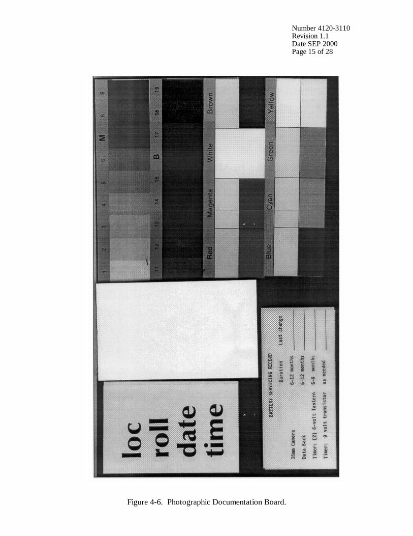
Number 4120-3110 Revision 1.1 Date SEP 2000 Page 15 of 28
Figure 4-6. Photographic Documentation Board.
Number 4120-3110 Revision 1.1 Date SEP 2000 Page 16 of 28
PHOTOGRAPH DOCUMENTATION BOARD (continued)
• Press the SHUTTER BUTTON. Verify that the film counter has incremented one frame.
• Reset the focus ring to infinity. The documentation chart should be evenly lit for the photograph. The board is mounted to the enclosed door with Velcro tabs and may be temporarily removed if proper lighting conditions are not possible in its normal position. You may have to shift your position slightly to find a spot where there is no glare from the sun on the board.
CHECK CAMERA BATTERY
Check the camera batteries by turning on the “main switch” and pressing the MODE and ISO buttons simultaneously. • All display panel indicators on - battery power sufficient
• All display panel indicators flashing* - low (have new
batteries on hand)
• No display panel indicators - drained or installed incorrectly (replace with new batteries or reinstall)
* As batteries lose voltage, the display panel will flash faster. If required, change the camera’s four AAA alkaline batteries and retest the system. Document all battery changes on the Visibility Monitoring Status/Assessment Sheet and “battery servicing record” portion of the documentation chart. Report any problems promptly to ARS. Camera battery change procedures are described further in Section 4.2.2.
CHECK CAMERA SETTINGS
Verify and change, if necessary, all camera settings for correct automatic operation. Standard settings for the Contax 167MT are: Main Switch ! Program Mode Selection AV ISO/ASA 64 Aperture f8.0 Drive Mode Selector S Exposure Compensation (zero) 0 Automatic Compensation Value Level 0&0 Lighting conditions of the target or vista may require site-specific exposure settings. Setting changes directed by ARS are documented on the enclosure door and in the Automatic 35 mm Camera System User’s Manual provided in the site operator’s manual.

Number 4120-3110 Revision 1.1 Date SEP 2000 Page 17 of 28
CHECK CAMERA SETTINGS (continued)
Document any settings that are different from those listed above on each Visibility Monitoring Status/Assessment Sheet.
CHECK DATABACK SETTING AND BATTERIES
The databack should be in the “year-month-day-time” mode displaying the current year, month, day, and time. If the display is flashing or blank, the databack batteries are drained. Replace the batteries only when the film is not loaded. Document all battery changes on the Visibility Monitoring Status/Assessment Sheet and “battery servicing record” portion of the documentation chart. Reset the databack for the current year, month, day, and time. Databack setting and programming instructions, as well as battery change procedures are described further in Section 4.2.
CHECK TIMER SETTINGS Review timer display: • The Paragon EC72D should be in the “RUN” mode
displaying the local time and day-of-week, and the colon should be flashing.
• If the display is incorrect press RUN on the display panel to verify that the timer is in the “RUN” mode. If the time, date, or display is still incorrect, reset the timer.
• If the timer display is blank, the timer battery wiring may be incorrect or the battery power may be insufficient.
Review the programmed timer events: • Press PRG then C1 to select Channel 1 for review.
• Press E repeatedly to review each event. In normal operation,
Event 1 (E:01) is 0900, Event 2 (E:02) is 1200, and Event 3 (E:03) is 1500. The remaining events are not programmed.
If events are incorrect, reprogram the timer clock and timer events. Timer setting and programming instructions are provided in Section 4.2.3. Press RUN when finished reviewing or changing events to return the timer to the “RUN” mode. NOTE: If a photograph was scheduled to occur while you
were reviewing or programming information, the photograph was not taken.
REPLACE AND ALIGN CAMERA
It is important for the alignment to be consistent from one roll to the next. • Mount the camera on the tripod head.
Number 4120-3110 Revision 1.1 Date SEP 2000 Page 18 of 28
REPLACE AND ALIGN CAMERA (continued)
• Press and move the QUICK RELEASE lever to the “L” (lock) position.
• Securely reconnect the camera/timer cable to the timer at the timer jack.
• Look through the viewfinder and align the camera on the vista to be photographed.
• Verify that the alignment matches the previous alignment, the horizon is level, the enclosure port does not appear in the frame, and the lens focus is on infinity. (A 3” x 5” site alignment photograph is provided in the camera enclosure for reference).
• Firmly tighten all levers on the tripod head and recheck the alignment.
If weather conditions obscure the target area, use foreground features to judge alignment. Visit the site again when the weather clears to recheck the alignment.
VERIFY CAMERA/TIMER CABLES AND FILM ADVANCE
Verify the camera/timer and power system (6 V lantern batteries) cable connections. Test the timer and battery cable connections: • The timer must be in the “RUN” mode, with the time and
day-of-week displayed and colon flashing.
• Press C1; the camera should fire. The timer automatically returns to the “RUN” mode.
If the camera does not fire, the camera/timer wiring is incorrect or the battery power to the timer is insufficient. Test the camera/timer cable connection: • Gently shake the camera/timer cable leading into the camera
remote jack. If the camera fires, an electrical short may exist in a portion of the cable jack(s).
• Observe the camera main lamp. The lamp should not illuminate for more than 20 seconds. If the lamp continues to illuminate beyond 20 seconds, an electrical short may exist in a portion of the cable jack.
Document any discrepancies and/or corrective actions taken. Report any problems promptly to ARS.
Number 4120-3110 Revision 1.1 Date SEP 2000 Page 19 of 28
DOCUMENT FINDINGS AND ACTIONS PERFORMED
Document any servicing or maintenance actions performed during the film loading process. Place the completed Visibility Monitoring Status/Assessment Sheet (yellow copy) in the Site Operator’s Manual for Automatic Visibility Monitoring Camera Systems.
CLOSE AND SECURE ENCLOSURE
Place the Site Operator’s Manual for Automatic Visibility Monitoring Camera Systems inside the camera enclosure for future reference. Close and lock the camera enclosure door. Tighten all door seal clamps and padlock the enclosure door hasp.
4.1.4 Mailing the Film and Completed Status/Assessment Sheet Place the original (white) copy of the Visibility Monitoring Status/Assessment Sheet and corresponding roll of film in a padded mailing envelope. Mail both the film and the Visibility Monitoring Status/Assessment Sheet immediately to: Air Resource Specialists, Inc. 1901 Sharp Point Drive, Suite E Fort Collins, CO 80525 Attention: Photographic Data Coordinator Call ARS immediately if any inconsistencies were noted or if any questions arise. Many problems can be resolved through telephone consultation. ARS may be reached at the following telephone numbers: Telephone: 970/484-7941 Fax: 970/484-3423 Detailed troubleshooting procedures to assist with telephone-directed problem resolution are presented in TI 4120-3310, Troubleshooting and Emergency Maintenance Procedures for 35 mm Automatic Camera System - Contax 167MT. 4.2 SCHEDULED MAINTENANCE Proper film storage and periodic preventive maintenance will help to ensure consistent, high quality data collection. Preventive maintenance servicing visits are performed as scheduled or required by the data coordinator. Scheduled maintenance normally consists of:
• Camera battery changes (every six months)
• Databack battery changes (annually)
• Timer battery changes (every six months)
Number 4120-3110 Revision 1.1 Date SEP 2000 Page 20 of 28
Replacement camera and timer batteries are provided by ARS with each film shipment (every six months). Replacement databack batteries are provided annually. Additional batteries will be provided as needed or as requested by the site operator. Test all batteries with a voltmeter before placing them in the system component. Verify all timer or camera battery malfunctions by testing removed component batteries with a voltmeter. Additional servicing tasks identified by the data coordinator may include:
• Camera, databack, and timer configuration checks or changes
• Camera alignment changes
• Revision of data collection procedures All scheduled maintenance requested by the data coordinator or performed by the site operator must be thoroughly documented on the Visibility Monitoring Status/Assessment Sheet and in the site-specific Quality Assurance Database. Any equipment malfunctions or data collection discrepancies observed during a scheduled maintenance visit should be reported to ARS immediately. The following subsections further describe proper methods for film storage, scheduled maintenance procedures, and corresponding servicing documentation. Troubleshooting and emergency maintenance procedures for the Contax 167MT are provided in TI 4120-3310, Troubleshooting and Emergency Maintenance Procedures for 35 mm Automatic Camera System - Contax 167MT. 4.2.1 Film and Film Storage Only Kodachrome 64 slide film provided by ARS should be loaded into the visibility monitoring camera unless otherwise directed. Each roll of film has an emulsion number and expiration date. This information must be documented on the canister label of each exposed film roll (see Section 4.1.3). Photographic film is sensitive to heat and moisture. These elements can affect the film, altering both the processed photographs and the data analysis. For example, film subjected to heat often has a pink or purple cast while film subjected to moisture does not process consistently. To ensure proper film storage, keep the film inside a Ziploc bag with desiccant and place the bag inside the clearly labeled film storage box. The box should be stored in a freezer, refrigerator, or cool (less than 70°F), dry location. If stored in a freezer, allow film to thaw at room temperature for at least two hours before loading it in the camera. 4.2.2 Changing System Batteries CAMERA BATTERY CHANGE
The Contax 167MT camera runs on four AAA alkaline batteries. The batteries should be replaced every six months or as directed by the data coordinator.
Number 4120-3110 Revision 1.1 Date SEP 2000 Page 21 of 28
CAMERA BATTERY CHANGE (continued)
• Loosen the battery compartment cover screw on the bottom of the camera. Remove the battery compartment cover and used batteries. Measure and record the voltage of the used batteries.
• Remove the new batteries from their packaging and test and record the voltage. Each new battery should measure at least 1.5 volts.
• Insert four batteries with polarity as indicated by the (+) and (-) markings on the battery compartment. The camera will not operate if the (+) and (-) ends are reversed.
• Fit the mounting hole on the battery compartment cover onto the guide pin on the camera body, return the cover to its original position, and close it with the fixing screw.
• After changing batteries, check them as described in Section 4.1.3.
DATABACK BATTERY CHANGE
The Contax 167MT Data Back D-7 runs on two 3 V coin-shaped lithium batteries. The databack batteries should be replaced annually, or as required by the data coordinator. Be sure to replace the batteries only when film is not loaded. • Open the camera back. The battery compartment is located on
the inside of the databack opposite the hinge. To open the compartment, turn the screw counterclockwise using a small Phillips-head screwdriver.
• Insert the screwdriver tip into the chamber and then gently push the used batteries. They will pop up and can then be removed. Measure and record the voltage of the used batteries.
• Remove the new batteries from their packaging and test and record the voltage. The new batteries should measure approximately 3 volts.
• Wait 15 seconds after removing the used batteries and then load the new batteries with the “+” side facing up.
• Load the new batteries into each chamber and replace the cover; tighten the screw securely.
• Check the display and reset the databack for the current date and time as described in Section 4.1.3.
TIMER BATTERY VERIFICATION AND CHANGES
The Paragon EC72D timer runs on two 6 V lantern batteries. Both 6 V lantern batteries should be replaced biannually or as directed by the data coordinator.
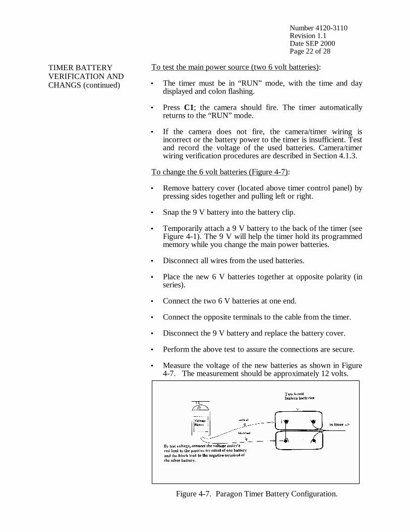
Number 4120-3110 Revision 1.1 Date SEP 2000 Page 22 of 28
TIMER BATTERY VERIFICATION AND CHANGS (continued)
To test the main power source (two 6 volt batteries): • The timer must be in “RUN” mode, with the time and day
displayed and colon flashing.
• Press C1; the camera should fire. The timer automatically returns to the “RUN” mode.
• If the camera does not fire, the camera/timer wiring is incorrect or the battery power to the timer is insufficient. Test and record the voltage of the used batteries. Camera/timer wiring verification procedures are described in Section 4.1.3.
To change the 6 volt batteries (Figure 4-7): • Remove battery cover (located above timer control panel) by
pressing sides together and pulling left or right.
• Snap the 9 V battery into the battery clip.
• Temporarily attach a 9 V battery to the back of the timer (see Figure 4-1). The 9 V will help the timer hold its programmed memory while you change the main power batteries.
• Disconnect all wires from the used batteries.
• Place the new 6 V batteries together at opposite polarity (in series).
• Connect the two 6 V batteries at one end.
• Connect the opposite terminals to the cable from the timer.
• Disconnect the 9 V battery and replace the battery cover.
• Perform the above test to assure the connections are secure.
• Measure the voltage of the new batteries as shown in Figure 4-7. The measurement should be approximately 12 volts.
Figure 4-7. Paragon Timer Battery Configuration.
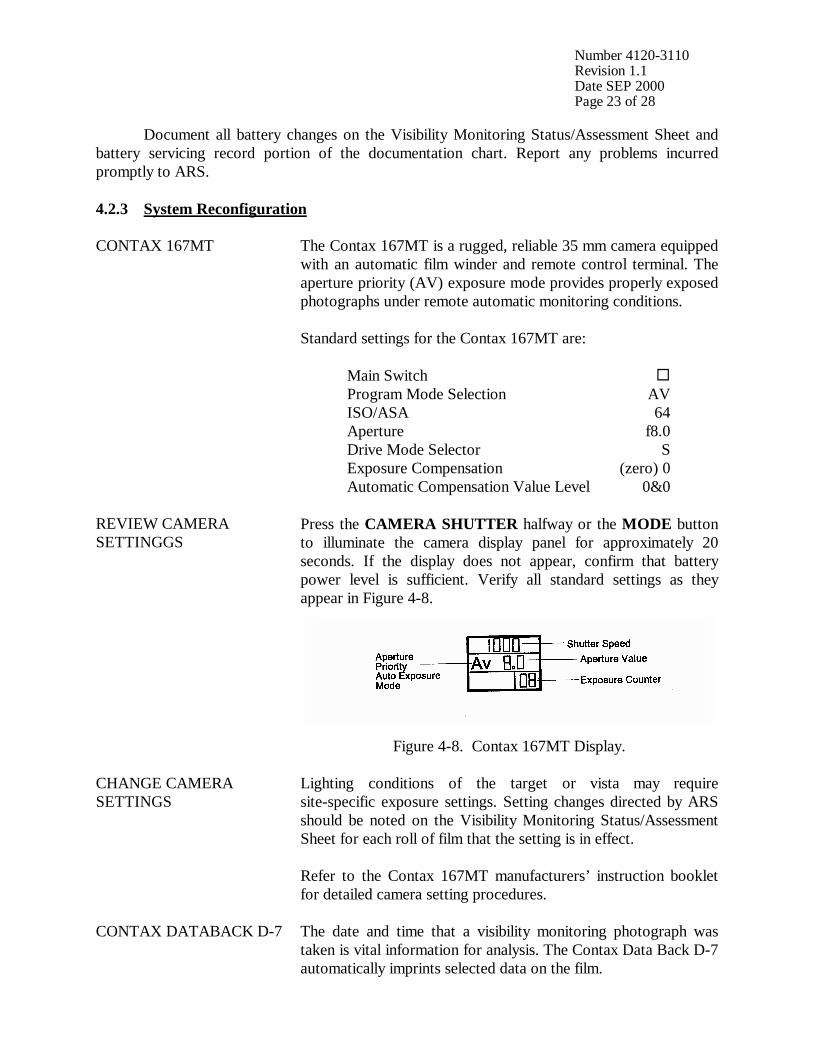
Number 4120-3110 Revision 1.1 Date SEP 2000 Page 23 of 28
Document all battery changes on the Visibility Monitoring Status/Assessment Sheet and battery servicing record portion of the documentation chart. Report any problems incurred promptly to ARS. 4.2.3 System Reconfiguration CONTAX 167MT The Contax 167MT is a rugged, reliable 35 mm camera equipped
with an automatic film winder and remote control terminal. The aperture priority (AV) exposure mode provides properly exposed photographs under remote automatic monitoring conditions. Standard settings for the Contax 167MT are: Main Switch ! Program Mode Selection AV ISO/ASA 64 Aperture f8.0 Drive Mode Selector S Exposure Compensation (zero) 0 Automatic Compensation Value Level 0&0
REVIEW CAMERA SETTINGGS
Press the CAMERA SHUTTER halfway or the MODE button to illuminate the camera display panel for approximately 20 seconds. If the display does not appear, confirm that battery power level is sufficient. Verify all standard settings as they appear in Figure 4-8.
Figure 4-8. Contax 167MT Display.
CHANGE CAMERA SETTINGS
Lighting conditions of the target or vista may require site-specific exposure settings. Setting changes directed by ARS should be noted on the Visibility Monitoring Status/Assessment Sheet for each roll of film that the setting is in effect. Refer to the Contax 167MT manufacturers’ instruction booklet for detailed camera setting procedures.
CONTAX DATABACK D-7 The date and time that a visibility monitoring photograph was taken is vital information for analysis. The Contax Data Back D-7 automatically imprints selected data on the film.
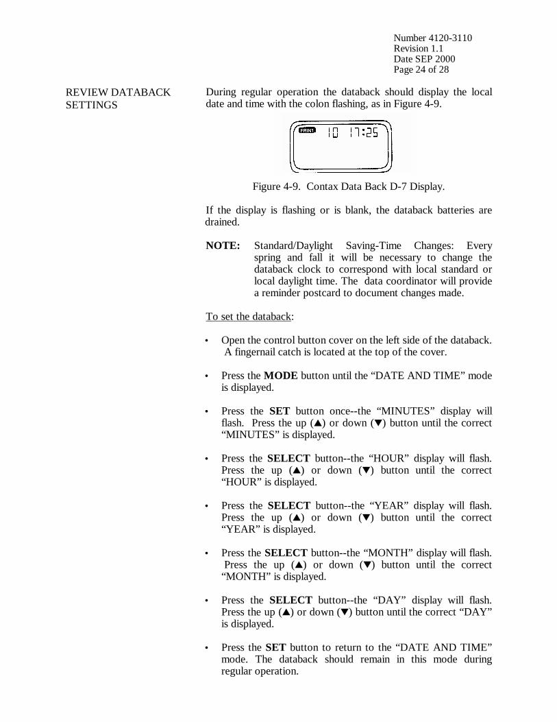
Number 4120-3110 Revision 1.1 Date SEP 2000 Page 24 of 28
REVIEW DATABACK SETTINGS
During regular operation the databack should display the local date and time with the colon flashing, as in Figure 4-9.
Figure 4-9. Contax Data Back D-7 Display. If the display is flashing or is blank, the databack batteries are drained. NOTE: Standard/Daylight Saving-Time Changes: Every spring and fall it will be necessary to change the databack clock to correspond with local standard or local daylight time. The data coordinator will provide a reminder postcard to document changes made. To set the databack: • Open the control button cover on the left side of the databack.
A fingernail catch is located at the top of the cover.
• Press the MODE button until the “DATE AND TIME” mode is displayed.
• Press the SET button once--the “MINUTES” display will flash. Press the up (!) or down (") button until the correct “MINUTES” is displayed.
• Press the SELECT button--the “HOUR” display will flash. Press the up (!) or down (") button until the correct “HOUR” is displayed.
• Press the SELECT button--the “YEAR” display will flash. Press the up (!) or down (") button until the correct “YEAR” is displayed.
• Press the SELECT button--the “MONTH” display will flash. Press the up (!) or down (") button until the correct “MONTH” is displayed.
• Press the SELECT button--the “DAY” display will flash. Press the up (!) or down (") button until the correct “DAY” is displayed.
• Press the SET button to return to the “DATE AND TIME” mode. The databack should remain in this mode during regular operation.
Number 4120-3110 Revision 1.1 Date SEP 2000 Page 25 of 28
PARAGON EC72D TIMER The Paragon automatic timer is normally programmed for three photographs a day at 0900, 1200, and 1500. If necessary, alternate sampling schedules can be programmed for 1 to 32 user-selected photographs a day. Routine servicing schedules are based on the number of photographs taken. • 3 photographs/day = 10-11 day servicing schedule.
• 2 photographs/day = 15-17 day servicing schedule.
• 1 photograph/day = 30-33 day servicing schedule. During regular operation the Paragon EC72D should be in the “RUN” mode displaying the local time and day-of-week (Sunday = 1; Saturday = 7) with the colon flashing.
SETTING THE PARAGON EC72D TIMER
To set the timer clock: • Wire power (two 6 V lantern batteries) to timer. A “0:00 1” is
displayed, with a colon and “1” flashing. Press CLK; the flashing stops.
• Using the 24-hour clock format, press four keys for the current time (e.g., 1015 = 10:15 a.m.). Press one key for the current date of the week; (1 = Sunday . . . 7 = Saturday). Press E to enter.
• “101” is displayed, indicating “January 1”. Press two keys for the current month and two keys for the current date (e.g., 0615 = June 15). Press E to enter.
• “84” is displayed, indicating “1984”. Press two keys for the current year (e.g., 90). Press E to enter. Control will automatically switch to the “RUN” mode. The time and day of week will be displayed with the colon flashing.
To program times for photographs to be taken: • Press PRG to enter “program” mode.
• Press C1 to select Channel 1 for programming; “E:01” (for
the first event) is displayed.
• Press four keys for the time the first photograph should be taken (e.g., 0900 for 9:00 a.m.). Press 0 to program the event to occur daily. Press E to enter the event into memory.
• The next event slot will be displayed (e.g., E:02). Repeat the step immediately above for each time of the day a photograph should be taken.
Number 4120-3110 Revision 1.1 Date SEP 2000 Page 26 of 28
SETTING THE PARAGON EC72D TIMER (continued)
• Press RUN to return to “RUN” mode after all selected photograph times are programmed.
Procedures to review programmed timer events are provided in Section 4.1.3. NOTE: If more than 16 photographs per day are desired, Channel 2 may be used to program up to 16 additional events provided the Channel 2 output terminals have also been wired to the camera.
SITE-SPECIFIC CAMERA ALIGNMENT
Correct alignment of the camera is extremely important. Each photograph is compared to others of the same view during analysis. Therefore, alignment must remain constant from one roll of film to the next. A 3” x 5” site alignment photograph is provided for your reference in the camera enclosure. Alignment changes or adjustments may be necessary when: • Selected features are not properly framed in the view, and/or
• Exposure discrepancies result from intruding foreground or
backlit features. Any alignment change directed by ARS should be fully documented on the Visibility Monitoring Status/Assessment Sheet.
VERIFY CAMERA ALIGNMENT
Look through the viewfinder to verify the following: • The alignment matches the referenced site-specific alignment
photograph.
• The horizon is level.
• The vista is framed correctly.
• The sunshield and port are not visible in the viewfinder.
• The lens focus is on infinity. Document any misalignment found and assess probable cause on the Visibility Monitoring Status/Assessment Sheet. If weather conditions obscure the target area, use foreground features to judge alignment. Visit the site again when the weather clears to recheck the alignment. Procedures to ensure ongoing alignment are provided in TI 4120-3310, Troubleshooting and Emergency Maintenance Procedures for 35 mm Automatic Camera System - Contax 167MT.
Number 4120-3110 Revision 1.1 Date SEP 2000 Page 27 of 28
4.2.4 On-Site Data Control During each routine site visit, the operator documents maintenance performed and notes all discrepancies on the Visibility Monitoring Status/Assessment Sheet. The completed original (white copy) is mailed with each roll of film. A copy (yellow) is kept in the Site Operator’s Manual for Automatic Visibility Monitoring Camera Systems. If discrepancies or operator comments on the sheets indicate that further action is necessary, immediate corrective action is taken. Throughout the monitoring effort, ARS and site operators maintain close personal communications. Operators are encouraged to call or notify ARS if they have questions or problems. Ongoing review of film and site operator documentation often initiates corrective actions. Common data collection problems identified include:
• Roll number discrepancies
• Missing or improperly exposed documentation chart photographs
• Improper film loading or rewinding
• Late film changes
• Improper camera alignment
• Incorrect camera settings
• Weak or missing databack imprinting
• Incorrect timer settings
• Incomplete Visibility Monitoring Status/Assessment Sheet documentation All scheduled maintenance requested by the data coordinator or performed by the site operator must be thoroughly documented on the Visibility Monitoring Status/Assessment Sheet and in the site-specific Quality Assurance Database. If necessary, a Photographic Monitoring Network Quality Assessment Log (Figure 4-10) is mailed to the site to further document corrective actions taken. The site operator documents the date of correction and what was done, and returns a carbon copy of the log to ARS. Problems and equipment malfunctions requiring extensive troubleshooting and/or maintenance are fully described in TI 4120-3310, Troubleshooting and Emergency Maintenance Procedures for 35 mm Automatic Camera System - Contax 167MT.
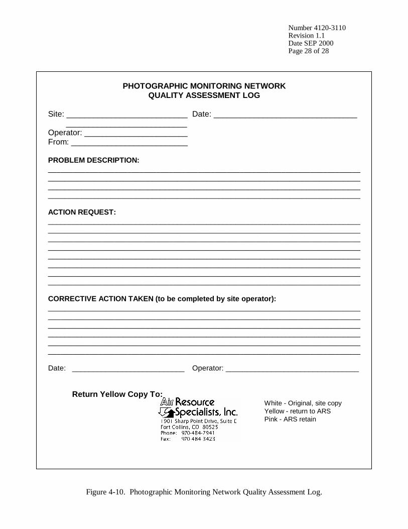
Number 4120-3110 Revision 1.1 Date SEP 2000 Page 28 of 28
PHOTOGRAPHIC MONITORING NETWORK QUALITY ASSESSMENT LOG
Site: ___________________________ Date: ________________________________ ___________________________ Operator: _______________________ From: __________________________ PROBLEM DESCRIPTION: ___________________________________________________________________________ ___________________________________________________________________________ ___________________________________________________________________________ ___________________________________________________________________________ ACTION REQUEST: ___________________________________________________________________________ ___________________________________________________________________________ ___________________________________________________________________________ ___________________________________________________________________________ ___________________________________________________________________________ ___________________________________________________________________________ ___________________________________________________________________________ ___________________________________________________________________________ CORRECTIVE ACTION TAKEN (to be completed by site operator): ___________________________________________________________________________ ___________________________________________________________________________ ___________________________________________________________________________ _________________________________________________________________________________________________________________________________________________________________________________________________________________________________ Date: ___________________________ Operator: ________________________________ Return Yellow Copy To: White - Original, site copy Yellow - return to ARS Pink - ARS retain
Figure 4-10. Photographic Monitoring Network Quality Assessment Log.
QUALITY ASSURANCE/QUALITY CONTROL DOCUMENTATION SERIES TITLE
ROUTINE SITE OPERATOR MAINTENANCE PROCEDURES FOR 35 MM AUTOMATIC CAMERA SYSTEM – CONTAX 137 MA
TYPE
TECHNICAL INSTRUCTION
NUMBER
4120-3120
DATE
OCTOBER 1993
AUTHORIZATIONS
TITLE NAME SIGNATURE
ORIGINATOR Karen K. Rosener
PROJECT MANAGER James H. Wagner
PROGRAM MANAGER David L. Dietrich
QA MANAGER Gloria S. Mercer
OTHER
REVISION HISTORY
REVISION NO.
CHANGE DESCRIPTION DATE AUTHORIZATIONS
Reviewed; no changes necessary. October 1994
Reviewed; no changes necessary. October 1995
1.0 Revise illustrations and forms. June 1996 Reviewed; no changes necessary. June 1997
Reviewed; no changes necessary. June 1998
Reviewed; no changes necessary. June 1999
Reviewed; no changes necessary. June 2000
1.1 Delete references to 9v battery in timer. September 2000
-- continued --
QUALITY ASSURANCE/QUALITY CONTROL DOCUMENTATION SERIES TITLE
ROUTINE SITE OPERATOR MAINTENANCE PROCEDURES FOR 35 MM AUTOMATIC CAMERA SYSTEM – CONTAX 137 MA
TYPE
TECHNICAL INSTRUCTION
NUMBER
4120-3120
DATE
OCTOBER 1993
AUTHORIZATIONS
TITLE NAME SIGNATURE
ORIGINATOR Karen K. Rosener
PROJECT MANAGER James H. Wagner
PROGRAM MANAGER David L. Dietrich
QA MANAGER Gloria S. Mercer
OTHER
REVISION HISTORY
REVISION NO.
CHANGE DESCRIPTION DATE AUTHORIZATIONS
Reviewed; no changes necessary. September 2001
Reviewed; no changes necessary. September 2002
Number 4120-3120 Revision 1.1 Date SEP 2000 Page i of ii
TABLE OF CONTENTS Section Page 1.0 PURPOSE AND APPLICABILITY 1 2.0 RESPONSIBILITIES 1 2.1 Project Manager 1 2.2 Field Specialist 1 2.3 Data Coordinator 2 2.4 Site Operator 2 3.0 REQUIRED EQUIPMENT AND MATERIALS 2 3.1 Site Visit Equipment 2 3.2 Inventory 4 4.0 METHODS 4 4.1 Routine Servicing 4 4.1.1 Status/Assessment Sheet General Information 9 4.1.2 Status/Assessment Sheet Film Removal Section 12 4.1.3 Status/Assessment Sheet Film Loading Section 13 4.1.4 Mailing the Film and Completed Status/Assessment Sheet 19 4.2 Scheduled Maintenance 19 4.2.1 Film and Film Storage 20 4.2.2 Changing System Batteries 21 4.2.3 System Reconfiguration 23 4.2.4 On-Site Data Control 27
LIST OF FIGURES Figure Page 4-1 Contax 137 MA System Components 6 4-2 Automatic 35 mm Camera System Tripod Assembly 7 4-3 Automatic 35 mm Camera System Enclosure 8 4-4 Example Automatic Camera Visibility Monitoring Status/Assessment Sheet for the Contax 137 MA Automatic Camera System 10 4-5 Completed Example of an Automatic Camera Visibility Monitoring Status/Assessment Sheet 11
Number 4120-3120 Revision 1.1 Date SEP 2000 Page ii of ii
LIST OF FIGURES (CONTINUED) Figure Page 4-6 Photographic Documentation Board 15 4-7 Paragon Timer Battery Configuration 23 4-8 Contax 137 MA Display 24 4-9 Contax Data Back D-5 Display 24 4-10 Photographic Monitoring Network Quality Assessment Log 29
LIST OF TABLES Table Page 4-1 Automatic Camera System Field Quality Control Procedures 5

Number 4120-3120 Revision 1.1 Date SEP 2000 Page 1 of 29
1.0 PURPOSE AND APPLICABILITY The purpose of routine site operator maintenance is to assure quality data capture and minimize data loss by performing and documenting scheduled operational checks and preventive maintenance. This technical instruction (TI) describes the steps of a routine site visit, scheduled maintenance, and on-site data control for the Contax 137 MA 35 mm camera system. Routine servicing schedules are based on the number of photographs taken each day. Assuming a three-photograph per day schedule, site operators service the camera approximately every 10 days to change film, check the performance of the camera system, clean system components, and perform troubleshooting and/or emergency maintenance as required. Preventive maintenance site visits are performed every six months or as required by the data coordinator. The effective performance and documentation of each of these tasks is the key to quality data collection and minimal data loss. Site operators should be fully trained and supplied with a Site Operator’s Manual for Automatic Visibility Monitoring Camera Systems that contains detailed routine site operator maintenance and troubleshooting procedures for the specific camera monitoring system(s) located at the site. Additional manufacturer instruction booklets and a supply of Visibility Monitoring Status/Assessment Sheets are also provided. Close personal communications should be maintained between Air Resource Specialists, Inc. (ARS) and site operators throughout the monitoring effort. Operators are encouraged to call or notify ARS if they have any questions or problems. Many problems can be fully resolved over the telephone. 2.0 RESPONSIBILITIES 2.1 PROJECT MANAGER The project manager shall coordinate with the site operator, his/her supervisor, field specialist, and data coordinator concerning the schedule and requirements for routine maintenance. 2.2 FIELD SPECIALIST The field specialist shall:
• Coordinate with the project manager, the site operator, his/her supervisor, and data coordinator concerning the schedule and requirements for routine maintenance.
• Train the site operator in all phases of camera system maintenance.
• Provide technical support to the site operator via telephone to assure high quality site
visits.
• Resolve problems reported by the site operator.
• Document all technical support provided to the site operator.
Number 4120-3120 Revision 1.1 Date SEP 2000 Page 2 of 29
2.3 DATA COORDINATOR The data coordinator shall:
• Coordinate with the project manager, the site operator, his/her supervisor, and field specialist concerning the schedule and requirements for routine maintenance.
• Verify that scheduled visits are performed and notify the site operator if he/she fails to
make a scheduled visit.
• Review all site documentation completed by the site operator for accuracy and completeness. File all documentation and correspondence.
• Resolve problems reported by the site operator.
• Enter the results of all performed procedures into the site-specific Quality Assurance
Database.
• Supply the site operator with all necessary monitoring supplies.
• Coordinate the replacement and repair of all malfunctioning units.
• Document all capital instrumentation changes and maintain inventory records in the ARS Purchase Order/Inventory Database.
2.4 SITE OPERATOR The site operator shall:
• Coordinate with his/her supervisor, the project manager, data coordinator, and field specialist concerning the schedule and requirements for routine maintenance.
• Schedule regular site maintenance visits and perform all procedures described in this
TI.
• Thoroughly document all procedures on the Visibility Monitoring Status/Assessment Sheet; mail the white copy of the completed sheet to the data coordinator and maintain an on-site file of the yellow copy.
• Immediately report any noted inconsistencies to the data coordinator or field specialist.
3.0 REQUIRED EQUIPMENT AND MATERIALS 3.1 SITE VISIT EQUIPMENT Equipment and materials generally required to support a routine site visit or scheduled maintenance include:
• Medium and small flat-blade screwdriver
• Small Phillips-head screwdriver
Number 4120-3120 Revision 1.1 Date SEP 2000 Page 3 of 29
• Medium adjustable wrench
• Keys for enclosure and padlocks
• Voltmeter
• Backup camera, databack, and timer batteries: - Contax 137 MA: - four AA alkaline batteries - Contax 137 MA Data Back D-5: - two 1.5 V silver oxide batteries - Paragon EC72D: - two 6 V lantern batteries
• Watch
• Lens cleaner and lens paper
• Site Operator’s Manual for Automatic Visibility Monitoring Camera Systems containing:
- SOP 4120, Automatic Camera System Maintenance (IMPROVE Protocol)
- TI 4120-3120, Routine Site Operator Maintenance Procedures for 35 mm
Automatic Camera System - Contax 137 MA
- TI 4120-3320, Troubleshooting and Emergency Maintenance Procedures for 35 mm Automatic Camera System - Contax 137 MA
- Automatic 35 mm Camera System User’s Manual
- Manufacturers’ instruction booklets
- Visibility Monitoring Status/Assessment Sheets
- Film canister labels
• Pen or pencil
• Grease pencil
• Supplemental visibility monitoring film
• Padded mailing envelopes
Number 4120-3120 Revision 1.1 Date SEP 2000 Page 4 of 29
3.2 INVENTORY It is imperative that any capital instrumentation changes made as a result of routine maintenance be thoroughly documented. Specific model and serial numbers of the exchanged enclosure, camera body, lens, databack, and/or automatic timer should be documented for future reference by the data coordinator in the site-specific Quality Assurance Database and ARS Purchase Order/Inventory Database. Any on-site changes made should be documented by the site operator on a Visibility Monitoring Status/Assessment Sheet. Capital equipment exchange procedures are discussed in TI 4120-3320, Troubleshooting and Emergency Maintenance Procedures for 35 mm Automatic Camera System - Contax 137 MA. 4.0 METHODS This section includes two (2) major subsections: 4.1 Routine Servicing 4.2 Scheduled Maintenance Detailed procedures described in these subsections are summarized in Table 4-1. A variety of automatic camera monitoring configurations exist. Specific equipment servicing requirements for each site will vary with the system configuration. All procedures described in this TI refer to the Contax 137 MA 35 mm camera and Paragon EC72D automatic timer. Routine servicing procedures are summarized in the Automatic 35 mm Camera System User’s Manual for the Contax 137 MA System, provided in the site operator’s manual. Detailed schematic diagrams of the Contax 137 MA 35 mm camera system and associated components are provided in Figures 4-1 through 4-3. The following manufacturers’ instruction booklets are provided for reference in the Site Operator’s Manual for Automatic Visibility Monitoring Camera Systems:
• Contax 137 MA Quartz
• Contax 137 MA Data Back D-5 Quartz
• Paragon EC72, EC72D, and EC72E Resolution of problems noted during routine servicing or scheduled maintenance can be more fully investigated by following the troubleshooting and emergency maintenance procedures defined in TI 4120-3320. 4.1 ROUTINE SERVICING Routine servicing schedules are based on the number of photographs taken each day. A common monitoring schedule includes taking three photographs a day at 0900, 1200, and 1500. Assuming this schedule, site operators service the camera approximately every 10 days. Alternate monitoring schedules are discussed in Section 4.2.3. Supplemental film and backup batteries should be on hand whenever the site is visited, this will minimize servicing time and data loss should a problem occur or be detected during servicing.

Number 4120-3120 Revision 1.1 Date SEP 2000 Page 5 of 29
Table 4-1
Automatic Camera System Field Quality Control Procedures
Regular Maintenance performed at each film change: • Inspect overall system and clean shelter window. • Remove camera. • Verify that film advanced and settings are correct. • Rewind and remove film (complete film canister label). • Load new film (complete film canister label). • Inspect and clean camera lens. • Check system batteries. • Check camera and databack settings. • Check timer settings. • Photograph film documentation board. • Replace and align camera. • Verify system operation. • Complete Visibility Monitoring Status/Assessment Sheets: - Document any equipment or monitoring discrepancies found. - Document all servicing or maintenance actions performed. - Describe weather conditions. - Describe visibility conditions. • Close and lock camera enclosure. • Mail film and the white copy of the completed Visibility Monitoring Status/Assessment
Sheet to ARS. Scheduled Maintenance performed as scheduled or as required: • Change 35 mm databack batteries annually. • Change 35 mm camera batteries every 6 months. • Change 35 mm timer batteries every 6 months.
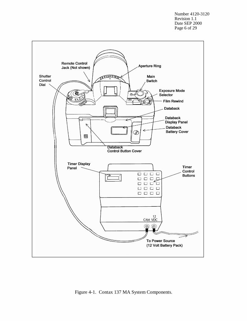
Number 4120-3120 Revision 1.1 Date SEP 2000 Page 6 of 29
Figure 4-1. Contax 137 MA System Components.
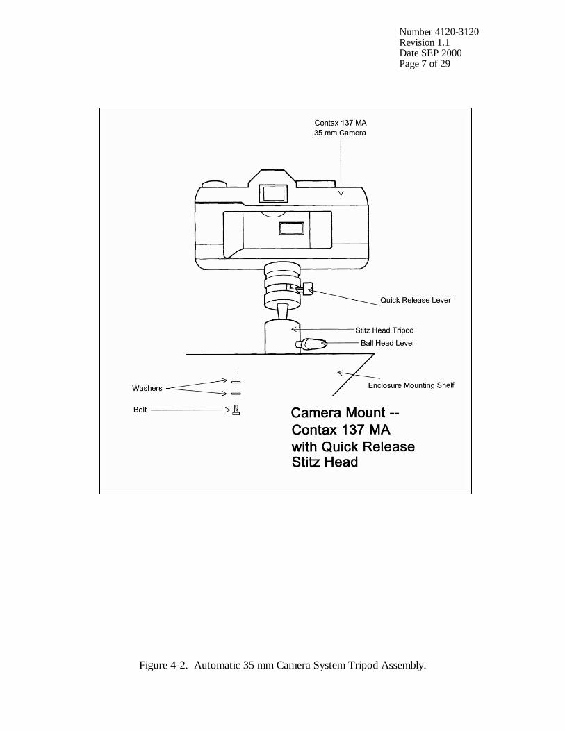
Number 4120-3120 Revision 1.1 Date SEP 2000 Page 7 of 29
Figure 4-2. Automatic 35 mm Camera System Tripod Assembly.
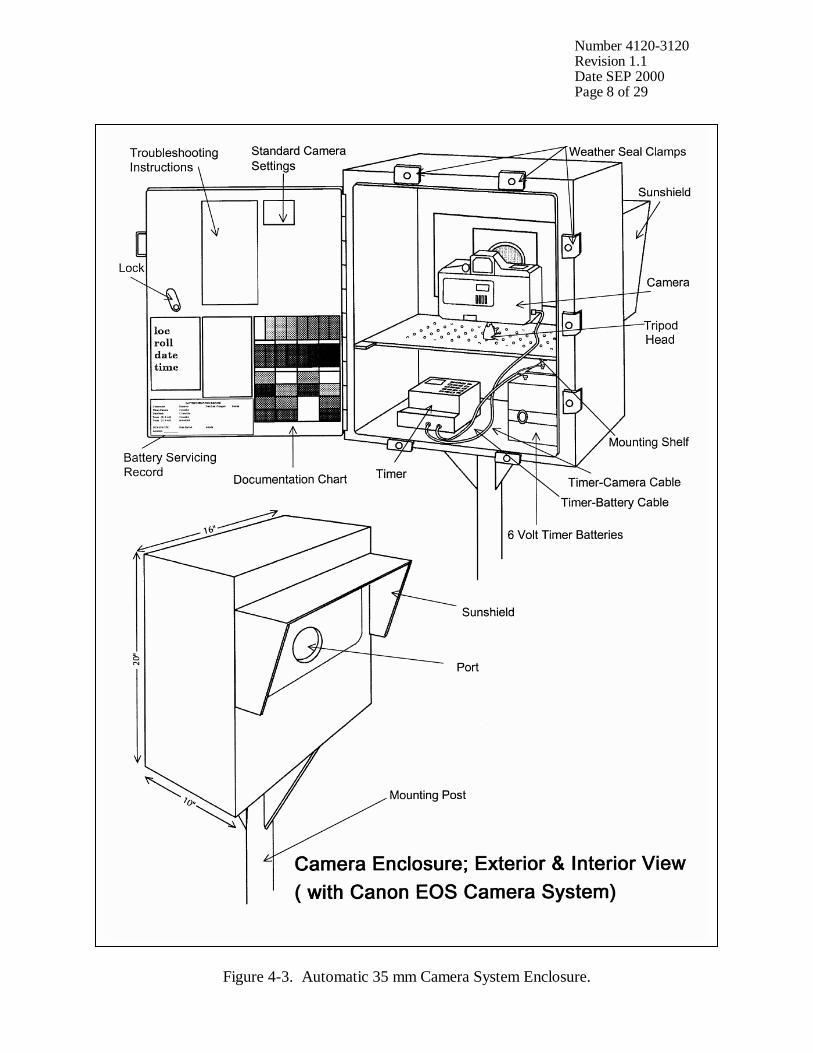
Number 4120-3120 Revision 1.1 Date SEP 2000 Page 8 of 29
Figure 4-3. Automatic 35 mm Camera System Enclosure.
Number 4120-3120 Revision 1.1 Date SEP 2000 Page 9 of 29
During each routine site visit, the operator will thoroughly document all pertinent data collection information, any maintenance performed, and note any equipment or monitoring discrepancies found on the Visibility Monitoring Status/Assessment Sheet (Figure 4-4). The site operator must complete all applicable portions of this sheet and mail the white original to the data coordinator with each roll of film. A completed example status/assessment sheet is provided in Figure 4-5. Blank status/assessment sheets are provided in the site operator’s manual. The following subsections detail how to complete the status/assessment sheet. 4.1.1 Status/Assessment Sheet General Information The following general information appears on the Visibility Monitoring Status/Assessment Sheet. LOCATION Either the full site location name or the four-letter site
abbreviation.
ROLL NO. The consecutive site roll number of the film used to document the monitoring period.
OPERATOR(S) The full name of the site operator(s).
DATE AND TIME The standard calendar date and local time when the film was loaded and when the film was removed.
WEATHER CONDITIONS At the time of film removal, describe recent and current weather conditions that may be helpful in interpreting the photographic data. Such conditions may include, but are not limited to: • Temperature extremes
• Percent cloud cover currently observed
• Severe weather (lightning, hail, high winds, etc.)
• Passing storm fronts
• Precipitation
• Stagnant air masses
• Fog
VISIBILITY CONDITIONS
Describe recent and current visibility conditions that may be useful in verifying qualitative photographic observations. Such conditions may include, but are not limited to: • Extremely clean
• Regional haze
• Layered haze
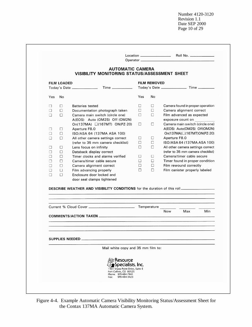
Number 4120-3120 Revision 1.1 Date SEP 2000 Page 10 of 29
Figure 4-4. Example Automatic Camera Visibility Monitoring Status/Assessment Sheet for the Contax 137MA Automatic Camera System.
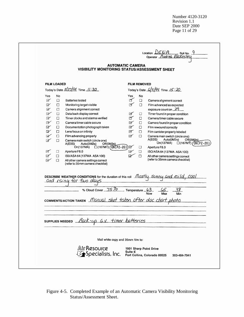
Number 4120-3120 Revision 1.1 Date SEP 2000 Page 11 of 29
Figure 4-5. Completed Example of an Automatic Camera Visibility Monitoring Status/Assessment Sheet.
Number 4120-3120 Revision 1.1 Date SEP 2000 Page 12 of 29
VISIBILITY CONDITIONS (continued)
• Plumes
• Severity of haze
• Emission source activity (e.g., nearby forest fires, controlled burns, construction, dusty roads, residential wood burning, etc.)
• Any perceptible odors (e.g., wood smoke)
COMMENTS Describe any equipment or monitoring discrepancies found, troubleshooting or scheduled maintenance performed, and/or corrective actions taken.
SUPPLIES NEEDED List any servicing supplies or documentation materials required for ongoing monitoring.
4.1.2 Status/Assessment Sheet Film Removal Section INSPECT ENCLOSURE Inspect the interior and exterior of the enclosure for damage or
other problems (water leakage, etc.). Inspect the outside of the enclosure window for dirt and clean if necessary.
VERIFY CAMERA ALIGNMENT
The camera alignment must remain constant from one roll to the next. Look through the camera viewfinder to verify that the alignment has remained correct during the monitoring period. If not, note the degree of misalignment and the probable cause.
VERIFY CAMERA/TIMER CABLES
Check the camera/timer and power system (6 V lantern batteries) cable connections. Verify that all cables are secure. Check the Check the integrity of the cables and component connectors. Document any problems, including broken connectors, loose or bare wires, etc. Report any problems promptly to ARS.
REMOVE CAMERA Press and move the QUICK RELEASE lever to the “R” (release) position and lift the camera off the mount. Disconnect the camera/timer cable from the timer at the timer jack and remove the camera from the enclosure.
DOCUMENT EXPOSURE NUMBER COUNT
The frame counter indicates if the film advanced properly and how many photographs were taken during the monitoring period. Document whether the film advanced correctly and the observed exposure count number. Report any discrepancies promptly to ARS.
VERIFY SETTINGS Verify all camera and timer settings. Document any settings that are different from those listed on the Visibility Monitoring Status/Assessment Sheet, whether they are site-specific settings or settings made in error. (Site-specific settings may be required at sites where non-standard exposure settings are necessary to ensure quality photographs). Correct any inconsistencies.
Number 4120-3120 Revision 1.1 Date SEP 2000 Page 13 of 29
REWIND FILM Open the rewind button cover (located next to the main switch) and press the REWIND button. The button should stay down; there is no need to keep pressing it. NOTE: The film will tear if this button is not pushed in before
attempting to rewind the film. Lift the FILM REWIND CRANK-HANDLE up and turn it in the direction of the arrow. While rewinding, you will feel a slight resistance. If the rewind crank is difficult to turn, check the “rewind release” button as described above. When the crank turns freely with no resistance, the film has been completely rewound into the cartridge. Do not open the camera back until you are sure that the film has been completely rewound. Open the camera back by pulling up on the rewind knob.
REMOVE FILM AND COMPLETE CANISTER LABEL
Remove exposed film from the camera and place it in the most recently labeled plastic canister. Complete the film canister label by writing in the current date and time. Inspect film compartment for fragments of film. Blow lightly into the compartment to remove film fragments or other particles. DO NOT TOUCH the shutter curtain.
COMPLETE VISIBILITY MONITORING STATUS/ASSESSMENT SHEET
Document: • Any equipment or monitoring discrepancies found. • All servicing or maintenance actions performed (e.g., date of
battery changes, cables tightened, timer re-programmed, etc.). • Current and recent weather conditions. • Current and recent visibility conditions.
4.1.3 Status/Assessment Sheet Film Loading Section LABEL FILM CANISTER
The film canister label identifies the contents of each roll of film. All of the information on the label is permanently logged at ARS when the film is received. Open a box of new, unexposed film and remove the plastic film canister. Fill out a film canister label with the following information and attach it to the outside of the plastic canister: • Monitoring site abbreviation
• Roll number
Number 4120-3120 Revision 1.1 Date SEP 2000 Page 14 of 29
LABEL FILM CANISTER (continued)
• Date and time loaded
• Emulsion number and expiration date (information listed on Kodak film box)
LOAD FILM To open the camera back, lift the REWIND CRANK HANDLE
and pull it up firmly. • Remove the film cartridge from the plastic film canister, open
the camera back, and insert the film cartridge into the film chamber.
• Pull the film leader across the shutter curtain and insert it into the film take-up spool.
• With the camera back open, press the SHUTTER RELEASE button to wind the film. Make sure the film has no slack and that its perforations are properly engaged with the sprocket teeth.
• Press the SHUTTER RELEASE button again until you are confident that the film is firmly connected to the take-up spool.
• Firmly close the camera back cover. Take additional exposures until “1” appears in the exposure counter.
NOTE: The exposure counter may advance even though the film is not loaded correctly. You can assume that the film is loaded correctly ONLY if the rewind shaft rotates when the shutter release is pressed. Store the empty, labeled plastic film canister inside the camera enclosure until the film is removed.
INSPECT CAMERA LENS Inspect the exterior of the UV filter mounted on the camera lens for any accumulation of dust, dirt, or fingerprints. If accumulation is noted: • Clean the outside of the UV filter with the lens paper and fluid
provided.
• If necessary, unscrew the UV filter and clean the lens and inside surface of the UV filter. Do not remove the lens from the camera body or attempt to clean inner surface of the lens.
• Use lens paper and fluid to clean the viewfinder eyepiece when necessary.
PHOTOGRAPH DOCUMENTATION BOARD
The first exposure on every roll must be of the documentation board which contains the gray scale, color chart, battery servicing record, and pertinent data collection information (Figure 4-6).
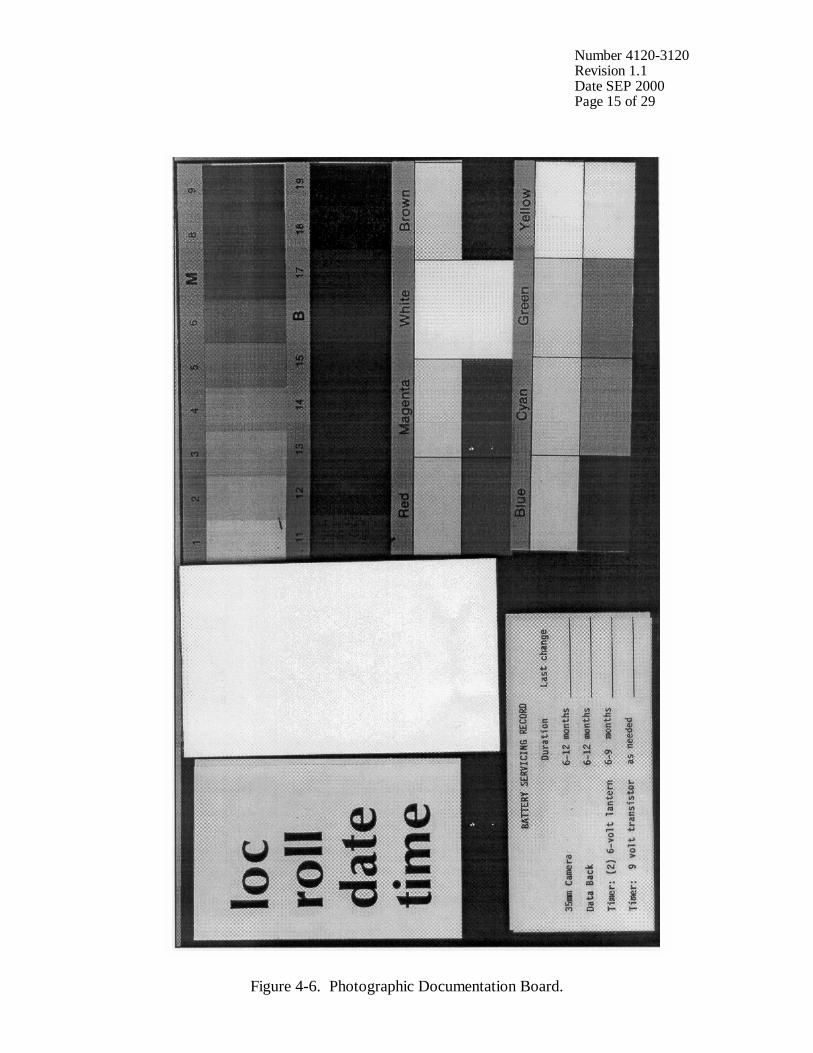
Number 4120-3120 Revision 1.1 Date SEP 2000 Page 15 of 29
Figure 4-6. Photographic Documentation Board.
Number 4120-3120 Revision 1.1 Date SEP 2000 Page 16 of 29
PHOTOGRAPH DOCUMENTATION BOARD (continued)
• Write the following on the note pad provided: - Monitoring site name or abbreviation - Roll number - Date and time • Adjust your position and turn the focus ring to achieve a
close-up, sharply focused photograph.
• Press the SHUTTER BUTTON. Verify that the film counter has incremented one frame.
• Reset the focus ring to infinity. The documentation chart should be evenly lit for the photograph The board is mounted to the enclosed door with Velcro tabs and may be temporarily removed if proper lighting conditions are not possible in its normal position. You may have to shift your position slightly to find a spot where there is no glare from the sun on the board.
CHECK CAMERA BATTERY
Check the camera batteries by turning on the “main switch” and pressing the MODE and ISO buttons simultaneously. • Bright Green Light - battery power sufficient
• Flashing or Dim Green Light - low (have new batteries on
hand)
• No Light - drained or installed incorrectly (replace with new batteries or reinstall)
If required, change the camera’s four AA alkaline batteries and retest the system. Document all battery changes on the Visibility Monitoring Status/Assessment Sheet and “battery servicing record” portion of the documentation chart. Report any problems promptly to ARS. Camera battery change procedures are described further in Section 4.2.2.
CHECK CAMERA SETTINGS
Verify and change, if necessary, all camera settings for correct automatic operation. Standard settings for the Contax 137 MA are: Main Switch ON Exposure Mode Selector S Shutter Control Dial A Exposure Compensation XI Film Speed ASA 100
Number 4120-3120 Revision 1.1 Date SEP 2000 Page 17 of 29
CHECK CAMERA SETTINGS (continued)
Aperture Ring F8 Focus Infinity Lighting conditions of the target or vista may require site-specific exposure settings. Setting changes directed by ARS are documented on the enclosure door and in the Automatic 35 mm Camera System User’s Manual provided in the site operator’s manual. Document any settings that are different from those listed above on each Visibility Monitoring Status/Assessment Sheet.
CHECK DATABACK SETTING AND BATTERIES
The databack should be in the “day-time” mode displaying the current day of the month and current time with the colon flashing. If the display is flashing or blank, the databack batteries are drained. Replace the batteries only when the film is not loaded. Document all battery changes on the Visibility Monitoring Status/Assessment Sheet and “battery servicing record” portion of the documentation chart. Reset the databack for the current date and time. Databack setting and programming instructions, as well as battery change procedures are described further in Section 4.2.
CHECK TIMER SETTINGS
Review timer display: • The Paragon EC72D should be in the “RUN” mode
displaying the local time and day-of-week, and the colon should be flashing.
• If the display is incorrect press RUN on the display panel to verify that the timer is in the “RUN” mode. If the time, date, or display is still incorrect, reset the timer.
• If the timer display is blank, the timer battery wiring may be incorrect or the battery power may be insufficient.
Review the programmed timer events: • Press PRG then C1 to select Channel 1 for review.
• Press E repeatedly to review each event. In normal operation,
Event 1 (E:01) is 0900, Event 2 (E:02) is 1200, and Event 3 (E:03) is 1500. The remaining events are not programmed.
If events are incorrect, reprogram the timer clock and timer events. Timer setting and programming instructions are provided in Section 4.2.3. Press RUN when finished reviewing or changing events to return the timer to the “RUN” mode.
Number 4120-3120 Revision 1.1 Date SEP 2000 Page 18 of 29
CHECK TIMER SETTINGS (continued)
NOTE: If a photograph was scheduled to occur while you were reviewing or programming information, the photograph was not taken.
REPLACE AND ALIGN CAMERA
It is important for the alignment to be consistent from one roll to the next. • Mount the camera on the tripod head.
• Press and move the QUICK RELEASE lever to the “L”
(lock) position.
• Securely reconnect the camera/timer cable to the timer at the timer jack.
• Look through the viewfinder and align the camera on the vista to be photographed.
• Verify that the alignment matches the previous alignment, the horizon is level, the enclosure port does not appear in the frame, and the lens focus is on infinity. (A 3” x 5” site alignment photograph is provided in the camera enclosure for reference).
• Firmly tighten all levers on the tripod head and recheck the alignment.
If weather conditions obscure the target area, use foreground features to judge alignment. Visit the site again when the weather clears to recheck the alignment.
VERIFY CAMERA/TIMER CABLES AND FILM ADVANCE
Verify the camera/timer and power system (6 V lantern batteries) cable connections. Test the timer and battery cable connections: • The timer must be in the “RUN” mode, with the time and
day-of-week displayed and colon flashing.
• Press C1; the camera should fire. The timer automatically returns to the “RUN” mode.
If the camera does not fire, the camera/timer wiring is incorrect or the battery power to the timer is insufficient. Test the camera/timer cable connection: • Gently shake the camera/timer cable leading into the camera
remote jack. If the camera fires, an electrical short may exist in a portion of the cable jack(s).
Number 4120-3120 Revision 1.1 Date SEP 2000 Page 19 of 29
VERIFY CAMERA/TIMER CABLES AND FILM ADVANCE (continued)
• Observe the camera main lamp. The lamp should not illuminate for more than 15 seconds. If the lamp continues to illuminate beyond 15 seconds, an electrical short may exist in a portion of the cable jack.
Document any discrepancies and/or corrective actions taken. Report any problems promptly to ARS.
DOCUMENT FINDINGS AND ACTIONS PERFORMED
Document any servicing or maintenance actions performed during the film loading process. Place the completed Visibility Monitoring Status/Assessment Sheet (yellow copy) in the Site Operator’s Manual for Automatic Visibility Monitoring Camera Systems.
CLOSE AND SECURE ENCLOSURE
Place the Site Operator’s Manual for Automatic Visibility Monitoring Camera Systems inside the camera enclosure for future reference. Close and lock the camera enclosure door. Tighten all door seal clamps and padlock the enclosure door hasp.
4.1.4 Mailing the Film and Completed Status/Assessment Sheet Place the original (white) copy of the Visibility Monitoring Status/Assessment Sheet and corresponding roll of film in a padded mailing envelope. Mail both the film and the Visibility Monitoring Status/Assessment Sheet immediately to: Air Resource Specialists, Inc. 1901 Sharp Point Drive, Suite E Fort Collins, CO 80525 Attention: Photographic Data Coordinator Call ARS immediately if any inconsistencies were noted or if any questions arise. Many problems can be resolved through telephone consultation. ARS may be reached at the following telephone numbers: Telephone: 970/484-7941 Fax: 970/484-3423 Detailed troubleshooting procedures to assist with telephone-directed problem resolution are presented in TI 4120-3320, Troubleshooting and Emergency Maintenance Procedures for 35 mm Automatic Camera System - Contax 137 MA. 4.2 SCHEDULED MAINTENANCE Proper film storage and periodic preventive maintenance will help to ensure consistent, high quality data collection. Preventive maintenance servicing visits are performed as scheduled or required by the data coordinator.
Number 4120-3120 Revision 1.1 Date SEP 2000 Page 20 of 29
Scheduled maintenance normally consists of:
• Camera battery changes (every six months)
• Databack battery changes (annually)
• Timer battery changes (every six months) Replacement camera and timer batteries are provided by ARS with each film shipment (every six months). Replacement databack batteries are provided annually. Additional batteries will be provided as needed or as requested by the site operator. Test all batteries with a voltmeter before placing them in the system component. Verify all timer or camera battery malfunctions by testing removed component batteries with a voltmeter. Additional servicing tasks identified by the data coordinator may include:
• Camera, databack, and timer configuration checks or changes
• Camera alignment changes
• Revision of data collection procedures All scheduled maintenance requested by the data coordinator or performed by the site operator must be thoroughly documented on the Visibility Monitoring Status/Assessment Sheet and in the site-specific Quality Assurance Database. Any equipment malfunctions or data collection discrepancies observed during a scheduled maintenance visit should be reported to ARS immediately. The following subsections further describe proper methods for film storage, scheduled maintenance procedures, and corresponding servicing documentation. Troubleshooting and emergency maintenance procedures for the Contax 137 MA are provided in TI 4120-3320, Troubleshooting and Emergency Maintenance Procedures for 35 mm Automatic Camera System - Contax 137 MA. 4.2.1 Film and Film Storage Only Kodachrome 64 slide film provided by ARS should be loaded into the visibility monitoring camera unless otherwise directed. Each roll of film has an emulsion number and expiration date. This information must be documented on the canister label of each exposed film roll (see Section 4.1.3). Photographic film is sensitive to heat and moisture. These elements can affect the film, altering both the processed photographs and the data analysis. For example, film subjected to heat often has a pink or purple cast while film subjected to moisture does not process consistently. To ensure proper film storage, keep the film inside a Ziploc bag with desiccant and place the bag inside the clearly labeled film storage box. The box should be stored in a freezer, refrigerator, or cool (less than 70°F), dry location. If stored in a freezer, allow film to thaw at room temperature for at least two hours before loading it in the camera.
Number 4120-3120 Revision 1.1 Date SEP 2000 Page 21 of 29
4.2.2 Changing System Batteries CAMERA BATTERY CHANGE
The Contax 137 MA camera runs on four AA alkaline batteries. The batteries should be replaced every six months or as directed by the data coordinator. • Lift up the fastening knob of the battery compartment cover
located on the bottom of the camera. Turn it in the OPEN direction and remove the battery compartment cover.
• Remove the new batteries from their packaging and test and record the voltage. Each new battery should measure at least 1.5 volts.
• Insert four batteries with polarity as indicated by the (+) and (-) markings on the battery compartment. The camera will not operate if the (+) and (-) ends are reversed.
• After installing the batteries in the battery case, insert it into the battery compartment in the direction shown by the diagram in the battery compartment.
• Fit the mounting hole on the battery compartment cover onto the guide pin on the camera body, return the cover to its original position, and lock it in place by turning the fastening knob as far as it will go in the direction of the white dot.
• After changing batteries, check them as described in Section 4.1.3.
DATABACK BATTERY CHANGE
The Contax 137 MA Data Back D-5 runs on two 1.5 V coin-shaped silver oxide batteries. The databack batteries should be replaced every six months, or as required by the data coordinator. Be sure to replace the batteries only when film is not loaded. • Insert a coin edge or other suitable object into the screwhead
located in the center of the battery compartment cover on the outside of the databack.
• Turn the screw counterclockwise and open the cover. Remove the used batteries. Measure and record the voltage of the used batteries.
• Remove the new batteries from their packaging and test and record the voltage. The new batteries should measure approximately 1.5 volts.
• Install two 1.5 V silver oxide batteries with their plus (+) marks facing upward. Replace the cover.
Number 4120-3120 Revision 1.1 Date SEP 2000 Page 22 of 29
DATABACK BATTERY CHANGE (continued)
• Check the display and reset the databack for the current date and time as described in Section 4.1.3.
TIMER BATTERY VERIFICATION AND CHANGES
The Paragon EC72D timer runs on two 6 V lantern batteries. Both 6 V lantern batteries should be replaced biannually or as directed by the data coordinator. To test the main power source (two 6 volt batteries): • The timer must be in “RUN” mode, with the time and day
displayed and colon flashing.
• Press C1; the camera should fire. The timer automatically returns to the “RUN” mode.
• If the camera does not fire, the camera/timer wiring is incorrect or the battery power to the timer is insufficient. Test and record the voltage of the used batteries. Camera/timer wiring verification procedures are described in Section 4.1.3.
To change the 6 volt batteries (Figure 4-7): • Remove battery cover (located above timer control panel) by
pressing sides together and pulling left or right.
• Snap a 9 V battery into the battery clip.
• Temporarily attach a 9 V battery to the back of the timer (see Figure 4-1). The 9 V will help the timer hold its programmed memory while you change the main power batteries.
• Disconnect all wires from the used batteries.
• Place the new 6 V batteries together at opposite polarity (in
series). • Connect the two 6 V batteries at one end.
• Connect the opposite terminals to the cable from the timer.
• Disconnect the 9 V battery and replace the battery cover.
• Perform the above test to assure the connections are secure.
• Measure the voltage of the new batteries as shown in Figure
4-7. The measurement should be approximately 12 volts.
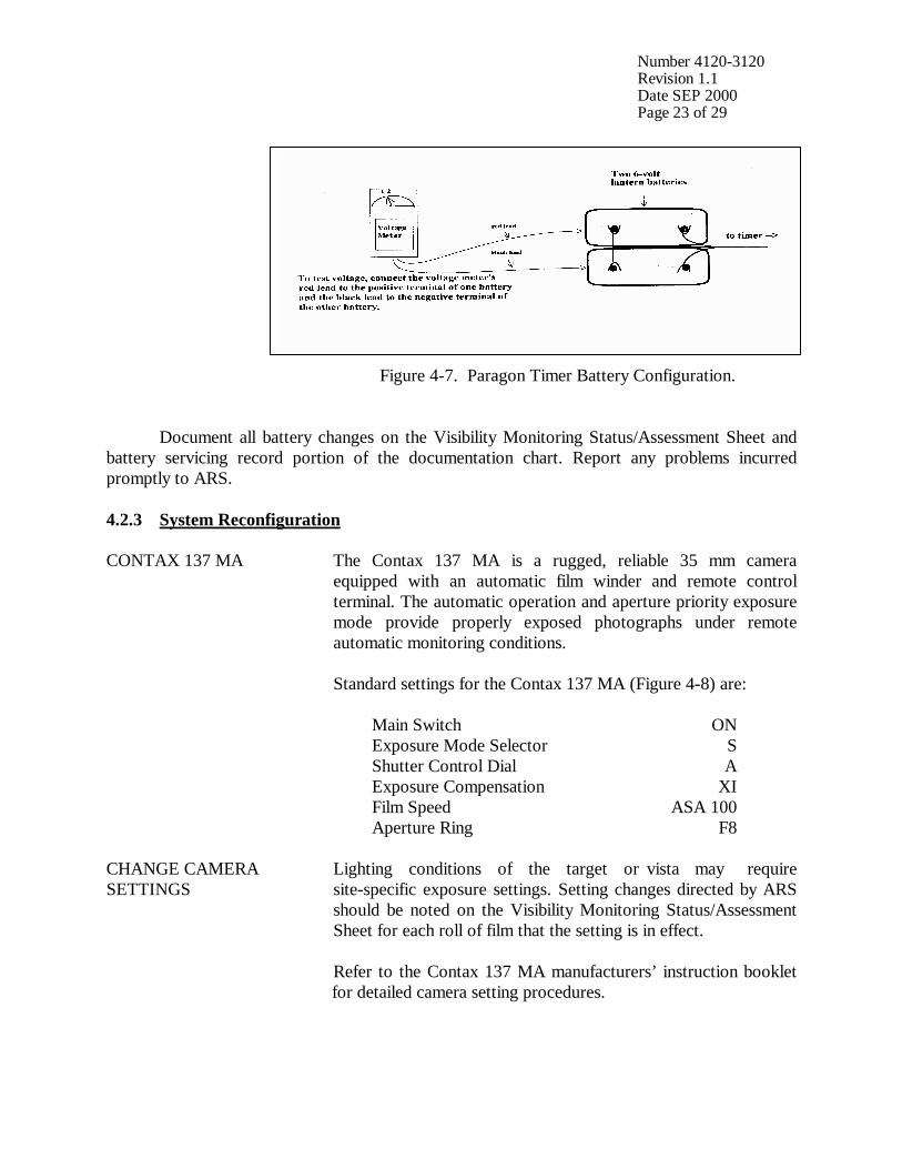
Number 4120-3120 Revision 1.1 Date SEP 2000 Page 23 of 29
Figure 4-7. Paragon Timer Battery Configuration. Document all battery changes on the Visibility Monitoring Status/Assessment Sheet and battery servicing record portion of the documentation chart. Report any problems incurred promptly to ARS. 4.2.3 System Reconfiguration CONTAX 137 MA The Contax 137 MA is a rugged, reliable 35 mm camera
equipped with an automatic film winder and remote control terminal. The automatic operation and aperture priority exposure mode provide properly exposed photographs under remote automatic monitoring conditions. Standard settings for the Contax 137 MA (Figure 4-8) are: Main Switch ON Exposure Mode Selector S Shutter Control Dial A Exposure Compensation XI Film Speed ASA 100 Aperture Ring F8
CHANGE CAMERA SETTINGS
Lighting conditions of the target or vista may require site-specific exposure settings. Setting changes directed by ARS should be noted on the Visibility Monitoring Status/Assessment Sheet for each roll of film that the setting is in effect. Refer to the Contax 137 MA manufacturers’ instruction booklet for detailed camera setting procedures.
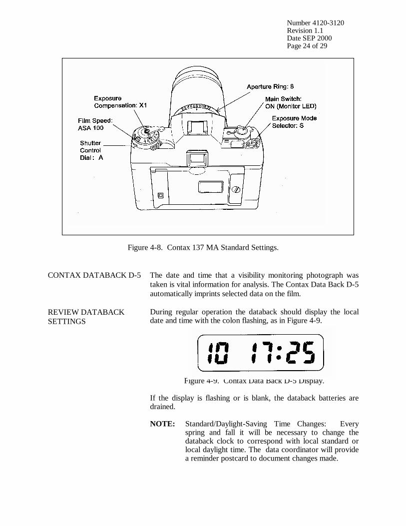
Number 4120-3120 Revision 1.1 Date SEP 2000 Page 24 of 29
Figure 4-8. Contax 137 MA Standard Settings. CONTAX DATABACK D-5 The date and time that a visibility monitoring photograph was
taken is vital information for analysis. The Contax Data Back D-5 automatically imprints selected data on the film.
REVIEW DATABACK SETTINGS
During regular operation the databack should display the local date and time with the colon flashing, as in Figure 4-9.
Figure 4-9. Contax Data Back D-5 Display. If the display is flashing or is blank, the databack batteries are drained. NOTE: Standard/Daylight-Saving Time Changes: Every spring and fall it will be necessary to change the databack clock to correspond with local standard or local daylight time. The data coordinator will provide a reminder postcard to document changes made.
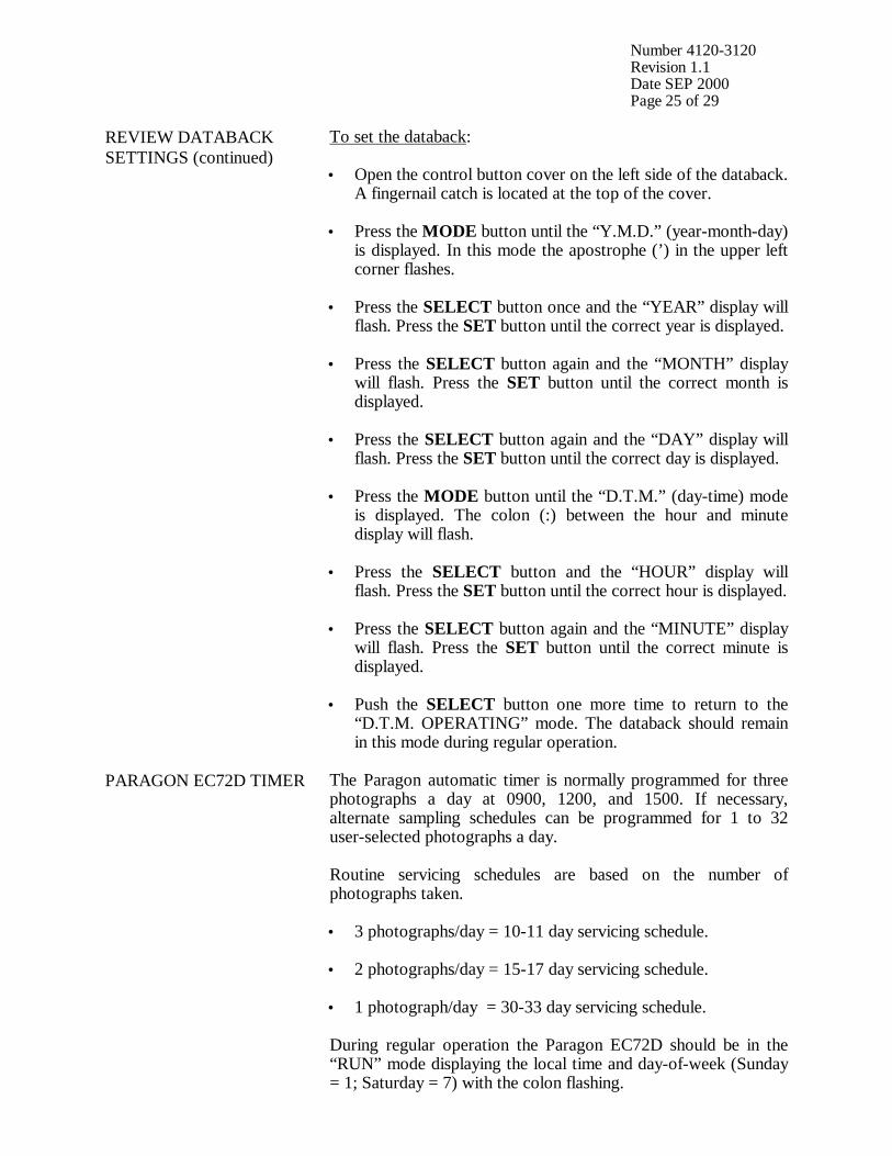
Number 4120-3120 Revision 1.1 Date SEP 2000 Page 25 of 29
REVIEW DATABACK SETTINGS (continued)
To set the databack: • Open the control button cover on the left side of the databack.
A fingernail catch is located at the top of the cover. • Press the MODE button until the “Y.M.D.” (year-month-day)
is displayed. In this mode the apostrophe (’) in the upper left corner flashes.
• Press the SELECT button once and the “YEAR” display will flash. Press the SET button until the correct year is displayed.
• Press the SELECT button again and the “MONTH” display will flash. Press the SET button until the correct month is displayed.
• Press the SELECT button again and the “DAY” display will
flash. Press the SET button until the correct day is displayed. • Press the MODE button until the “D.T.M.” (day-time) mode
is displayed. The colon (:) between the hour and minute display will flash.
• Press the SELECT button and the “HOUR” display will flash. Press the SET button until the correct hour is displayed.
• Press the SELECT button again and the “MINUTE” display will flash. Press the SET button until the correct minute is displayed.
• Push the SELECT button one more time to return to the “D.T.M. OPERATING” mode. The databack should remain in this mode during regular operation.
PARAGON EC72D TIMER
The Paragon automatic timer is normally programmed for three photographs a day at 0900, 1200, and 1500. If necessary, alternate sampling schedules can be programmed for 1 to 32 user-selected photographs a day. Routine servicing schedules are based on the number of photographs taken. • 3 photographs/day = 10-11 day servicing schedule.
• 2 photographs/day = 15-17 day servicing schedule.
• 1 photograph/day = 30-33 day servicing schedule. During regular operation the Paragon EC72D should be in the “RUN” mode displaying the local time and day-of-week (Sunday = 1; Saturday = 7) with the colon flashing.
Number 4120-3120 Revision 1.1 Date SEP 2000 Page 26 of 29
SETTING THE PARAGON EC72D TIMER
To set the timer clock: • Wire power (two 6 V lantern batteries) to timer. A “0:00 1” is
displayed, with a colon and “1” flashing. Press CLK; the flashing stops.
• Using the 24-hour clock format, press four keys for the current time (e.g., 1015 = 10:15 a.m.). Press one key for the current date of the week; (1 = Sunday . . . 7 = Saturday). Press E to enter.
• “101” is displayed, indicating “January 1”. Press two keys for the current month and two keys for the current date (e.g., 0615 = June 15). Press E to enter.
• “84” is displayed, indicating “1984”. Press two keys for the
current year (e.g., 90). Press E to enter. Control will automatically switch to the “RUN” mode. The time and day of week will be displayed with the colon flashing.
To program times for photographs to be taken: • Press PRG to enter “program” mode.
• Press C1 to select Channel 1 for programming; “E:01” (for
the first event) is displayed.
• Press four keys for the time the first photograph should be taken (e.g., 0900 for 9:00 a.m.). Press 0 to program the event to occur daily. Press E to enter the event into memory.
• The next event slot will be displayed (e.g., E:02). Repeat the step immediately above for each time of the day a photograph should be taken.
• Press RUN to return to “RUN” mode after all selected photograph times are programmed.
Procedures to review programmed timer events are provided in Section 4.1.3. NOTE: If more than 16 photographs per day are desired,
Channel 2 may be used to program up to 16 additional events provided the Channel 2 output terminals have also been wired to the camera.
SITE-SPECIFIC CAMERA ALIGNMENT
Correct alignment of the camera is extremely important. Each photograph is compared to others of the same view during analysis. Therefore, alignment must remain constant from one roll of film to the next.

Number 4120-3120 Revision 1.1 Date SEP 2000 Page 27 of 29
SITE-SPECIFIC CAMERA ALIGNMENT (continued)
A 3” x 5” site alignment photograph is provided for your reference in the camera enclosure. Alignment changes or adjustments may be necessary when: • Selected features are not properly framed in the view, and/or
• Exposure discrepancies result from intruding foreground or
backlit features. Any alignment change directed by ARS should be fully documented on the Visibility Monitoring Status/Assessment Sheet.
VERIFY CAMERA ALIGNMENT
Look through the viewfinder to verify the following: • The alignment matches the referenced site-specific alignment
photograph.
• The horizon is level.
• The vista is framed correctly.
• The sunshield and port are not visible in the viewfinder.
• The lens focus is on infinity. Document any misalignment found and assess probable cause on the Visibility Monitoring Status/Assessment Sheet. If weather conditions obscure the target area, use foreground features to judge alignment. Visit the site again when the weather clears to recheck the alignment. Procedures to ensure ongoing alignment are provided in TI 4120-3320, Troubleshooting and Emergency Maintenance Procedures for 35 mm Automatic Camera System - Contax 137 MA.
4.2.4 On-Site Data Control During each routine site visit, the operator documents maintenance performed and notes all discrepancies on the Visibility Monitoring Status/Assessment Sheet. The completed original (white copy) is mailed with each roll of film. A copy (yellow) is kept in the Site Operator’s Manual for Automatic Visibility Monitoring Camera Systems. If discrepancies or operator comments on the sheets indicate that further action is necessary, immediate corrective action is taken. Throughout the monitoring effort, ARS and site operators maintain close personal communications. Operators are encouraged to call or notify ARS if they have questions or problems. Ongoing review of film and site operator documentation often initiates corrective actions.
Number 4120-3120 Revision 1.1 Date SEP 2000 Page 28 of 29
Common data collection problems identified include:
• Roll number discrepancies
• Missing or improperly exposed documentation chart photographs
• Improper film loading or rewinding
• Late film changes
• Improper camera alignment
• Incorrect camera settings
• Weak or missing databack imprinting
• Incorrect timer settings
• Incomplete Visibility Monitoring Status/Assessment Sheet documentation All scheduled maintenance requested by the data coordinator or performed by the site operator must be thoroughly documented on the Visibility Monitoring Status/Assessment Sheet and in the site-specific Quality Assurance Database. If necessary, a Photographic Monitoring Network Quality Assessment Log (Figure 4-10) is mailed to the site to further document corrective actions taken. The site operator documents the date of correction and what was done, and returns a carbon copy of the log to ARS. Problems and equipment malfunctions requiring extensive troubleshooting and/or maintenance are fully described in TI 4120-3320.

Number 4120-3120 Revision 1.1 Date SEP 2000 Page 29 of 29
PHOTOGRAPHIC MONITORING NETWORK QUALITY ASSESSMENT LOG
Site: __________________________ Date: ________________________________ __________________________ Operator: ______________________ From: _________________________ PROBLEM DESCRIPTION: ___________________________________________________________________________ ___________________________________________________________________________ ___________________________________________________________________________ ___________________________________________________________________________ ACTION REQUEST: ___________________________________________________________________________ ___________________________________________________________________________ ___________________________________________________________________________ ___________________________________________________________________________ ___________________________________________________________________________ ___________________________________________________________________________ ___________________________________________________________________________ ___________________________________________________________________________ CORRECTIVE ACTION TAKEN (to be completed by site operator): ___________________________________________________________________________ ___________________________________________________________________________ ___________________________________________________________________________ ___________________________________________________________________________ ___________________________________________________________________________ ___________________________________________________________________________ Date: ________________________ Operator: ________________________________
Return Yellow Copy To: White - Original, site copy Yellow - return to ARS Pink - ARS retain Figure 4-10. Photographic Monitoring Network Quality Assessment Log.

QUALITY ASSURANCE/QUALITY CONTROL DOCUMENTATION SERIES TITLE
ROUTINE SITE OPERATOR MAINTENANCE PROCEDURES FOR 35 MM AUTOMATIC CAMERA SYSTEM – OLYMPUS OM2N
TYPE
TECHNICAL INSTRUCTION
NUMBER
4120-3130
DATE
JANUARY 1994
AUTHORIZATIONS
TITLE NAME SIGNATURE
ORIGINATOR Kristi Savig
PROJECT MANAGER James H. Wagner
PROGRAM MANAGER David L. Dietrich
QA MANAGER Gloria S. Mercer
OTHER
REVISION HISTORY
REVISION NO.
CHANGE DESCRIPTION DATE AUTHORIZATIONS
Reviewed; no changes necessary. January 1995
Reviewed; no changes necessary. January 1996
1.0 Revise illustrations and forms. June 1996
Reviewed; no changes necessary. June 1997
Reviewed; no changes necessary. June 1998
Reviewed; no changes necessary. June 1999
Reviewed; no changes necessary. June 2000
1.1 Delete references to 9v battery in timer. September 2000
-- continued --
QUALITY ASSURANCE/QUALITY CONTROL DOCUMENTATION SERIES TITLE
ROUTINE SITE OPERATOR MAINTENANCE PROCEDURES FOR 35 MM AUTOMATIC CAMERA SYSTEM – OLYMPUS OM2N
TYPE
TECHNICAL INSTRUCTION
NUMBER
4120-3130
DATE
JANUARY 1994
AUTHORIZATIONS
TITLE NAME SIGNATURE
ORIGINATOR Kristi Savig
PROJECT MANAGER James H. Wagner
PROGRAM MANAGER David L. Dietrich
QA MANAGER Gloria S. Mercer
OTHER
REVISION HISTORY
REVISION NO.
CHANGE DESCRIPTION DATE AUTHORIZATIONS
Reviewed; no changes necessary. September 2001
Reviewed; no changes necessary. September 2002

Number 4120-3130 Revision 1.1 Date SEP 2000 Page i of ii
TABLE OF CONTENTS Section Page 1.0 PURPOSE AND APPLICABILITY 1 2.0 RESPONSIBILITIES 1 2.1 Project Manager 1 2.2 Field Specialist 1 2.3 Data Coordinator 2 2.4 Site Operator 2 3.0 REQUIRED EQUIPMENT AND MATERIALS 2 3.1 Site Visit Equipment 2 3.2 Inventory 4 4.0 METHODS 4 4.1 Routine Servicing 4 4.1.1 Status/Assessment Sheet General Information 9 4.1.2 Status/Assessment Sheet Film Removal Section 12 4.1.3 Status/Assessment Sheet Film Loading Section 13 4.1.4 Mailing the Film and Completed Status/Assessment Sheet 19 4.2 Scheduled Maintenance 19 4.2.1 Film and Film Storage 20 4.2.2 Changing System Batteries 20 4.2.3 System Reconfiguration 23 4.2.4 On-Site Data Control 27
LIST OF FIGURES Figure Page 4-1 Olympus OM2N System Components 6 4-2 Automatic 35 mm Camera System Tripod Assembly 7 4-3 Automatic 35 mm Camera System Enclosure 8 4-4 Example Automatic Camera Visibility Monitoring Status/Assessment Sheet for the Olympus OM2N Automatic Camera System 10
Number 4120-3130 Revision 1.1 Date SEP 2000 Page ii of ii
LIST OF FIGURES (CONTINUED) Figure Page 4-5 Completed Example of an Automatic Camera Visibility Monitoring Status/ Assessment Sheet 11 4-6 Photographic Documentation Board 15 4-7 Paragon Timer Battery Configuration 22 4-8 Olympus Recordata Back Displays 23 4-9 Photographic Monitoring Network Quality Assessment Log 29
LIST OF TABLES Table Page 4-1 Automatic Camera System Field Quality Control Procedures 5
Number 4120-3130 Revision 1.1 Date SEP 2000 Page 1 of 29
1.0 PURPOSE AND APPLICABILITY The purpose of routine site operator maintenance is to assure quality data capture and minimize data loss by performing and documenting scheduled operational checks and preventive maintenance. This technical instruction (TI) describes the steps of a routine site visit, scheduled maintenance, and on-site data control for the Olympus OM2N 35 mm camera system. Routine servicing schedules are based on the number of photographs taken each day. Assuming a three-photograph per day schedule, site operators service the camera approximately every 10 days to change film, check the performance of the camera system, clean system components, and perform troubleshooting and/or emergency maintenance as required. Preventive maintenance site visits are performed every six months or as required by the data coordinator. The effective performance and documentation of each of these tasks is the key to quality data collection and minimal data loss. Site operators should be fully trained and supplied with a Site Operator’s Manual for Automatic Visibility Monitoring Camera Systems that contains detailed routine site operator maintenance and troubleshooting procedures for the specific camera monitoring system(s) located at the site. Additional manufacturer instruction booklets and a supply of Visibility Monitoring Status/Assessment Sheets are also provided. Close personal communications should be maintained between Air Resource Specialists, Inc. (ARS) and site operators throughout the monitoring effort. Operators are encouraged to call or notify ARS if they have any questions or problems. Many problems can be fully resolved over the telephone. 2.0 RESPONSIBILITIES 2.1 PROJECT MANAGER The project manager shall coordinate with the site operator, his/her supervisor, field specialist, and data coordinator concerning the schedule and requirements for routine maintenance. 2.2 FIELD SPECIALIST The field specialist shall:
• Coordinate with the project manager, the site operator, his/her supervisor, and data coordinator concerning the schedule and requirements for routine maintenance.
• Train the site operator in all phases of camera system maintenance.
• Provide technical support to the site operator via telephone to assure high quality site
visits.
• Resolve problems reported by the site operator.
• Document all technical support provided to the site operator.

Number 4120-3130 Revision 1.1 Date SEP 2000 Page 2 of 29
2.3 DATA COORDINATOR The data coordinator shall:
• Coordinate with the project manager, the site operator, his/her supervisor, and field specialist concerning the schedule and requirements for routine maintenance.
• Verify that scheduled visits are performed and notify the site operator if he/she fails to
make a scheduled visit.
• Review all site documentation completed by the site operator for accuracy and completeness. File all documentation and correspondence.
• Resolve problems reported by the site operator.
• Enter the results of all performed procedures into the site-specific Quality Assurance
Database.
• Supply the site operator with all necessary monitoring supplies.
• Coordinate the replacement and repair of all malfunctioning units.
• Document all capital instrumentation changes and maintain inventory records in the ARS Purchase Order/Inventory Database.
2.4 SITE OPERATOR The site operator shall:
• Coordinate with his/her supervisor, the project manager, data coordinator, and field specialist concerning the schedule and requirements for routine maintenance.
• Schedule regular site maintenance visits and perform all procedures described in this
TI.
• Thoroughly document all procedures on the Visibility Monitoring Status/Assessment Sheet; mail the white copy of the completed sheet to the data coordinator and maintain an on-site file of the yellow copy.
• Immediately report any noted inconsistencies to the data coordinator or field specialist.
3.0 REQUIRED EQUIPMENT AND MATERIALS 3.1 SITE VISIT EQUIPMENT Equipment and materials generally required to support a routine site visit or scheduled maintenance include:
• Medium and small flat-blade screwdriver
• Small Phillips-head screwdriver • Medium adjustable wrench

Number 4120-3130 Revision 1.1 Date SEP 2000 Page 3 of 29
• Keys for enclosure and padlocks
• Voltmeter
• Backup camera, databack, and timer batteries:
- Olympus OM2N: - two 1.5 V silver oxide batteries - Olympus Recordata Back 3 or 4: - two 1.5 V silver oxide batteries - Paragon EC72D: - two 6 V lantern batteries
• Watch
• Lens cleaner and lens paper
• Site Operator’s Manual for Automatic Visibility Monitoring Camera Systems containing:
- SOP 4120, Automatic Camera System Maintenance (IMPROVE Protocol) - TI 4120-3130, Routine Site Operator Maintenance Procedures for 35 mm
Automatic Camera System - Olympus OM2N - TI 4120-3330, Troubleshooting and Emergency Maintenance Procedures for
35 mm Automatic Camera System - Olympus OM2N - Automatic 35 mm Camera System User’s Manual - Manufacturers’ instruction booklets - Visibility Monitoring Status/Assessment Sheets - Film canister labels
• Pen or pencil
• Grease pencil
• Supplemental visibility monitoring film
• Padded mailing envelopes
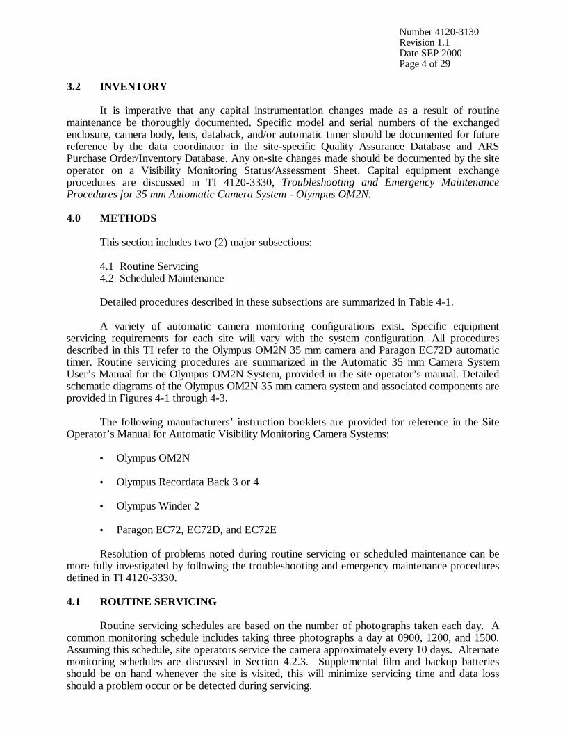
Number 4120-3130 Revision 1.1 Date SEP 2000 Page 4 of 29
3.2 INVENTORY It is imperative that any capital instrumentation changes made as a result of routine maintenance be thoroughly documented. Specific model and serial numbers of the exchanged enclosure, camera body, lens, databack, and/or automatic timer should be documented for future reference by the data coordinator in the site-specific Quality Assurance Database and ARS Purchase Order/Inventory Database. Any on-site changes made should be documented by the site operator on a Visibility Monitoring Status/Assessment Sheet. Capital equipment exchange procedures are discussed in TI 4120-3330, Troubleshooting and Emergency Maintenance Procedures for 35 mm Automatic Camera System - Olympus OM2N. 4.0 METHODS This section includes two (2) major subsections: 4.1 Routine Servicing 4.2 Scheduled Maintenance Detailed procedures described in these subsections are summarized in Table 4-1. A variety of automatic camera monitoring configurations exist. Specific equipment servicing requirements for each site will vary with the system configuration. All procedures described in this TI refer to the Olympus OM2N 35 mm camera and Paragon EC72D automatic timer. Routine servicing procedures are summarized in the Automatic 35 mm Camera System User’s Manual for the Olympus OM2N System, provided in the site operator’s manual. Detailed schematic diagrams of the Olympus OM2N 35 mm camera system and associated components are provided in Figures 4-1 through 4-3. The following manufacturers’ instruction booklets are provided for reference in the Site Operator’s Manual for Automatic Visibility Monitoring Camera Systems:
• Olympus OM2N
• Olympus Recordata Back 3 or 4
• Olympus Winder 2
• Paragon EC72, EC72D, and EC72E Resolution of problems noted during routine servicing or scheduled maintenance can be more fully investigated by following the troubleshooting and emergency maintenance procedures defined in TI 4120-3330. 4.1 ROUTINE SERVICING Routine servicing schedules are based on the number of photographs taken each day. A common monitoring schedule includes taking three photographs a day at 0900, 1200, and 1500. Assuming this schedule, site operators service the camera approximately every 10 days. Alternate monitoring schedules are discussed in Section 4.2.3. Supplemental film and backup batteries should be on hand whenever the site is visited, this will minimize servicing time and data loss should a problem occur or be detected during servicing.
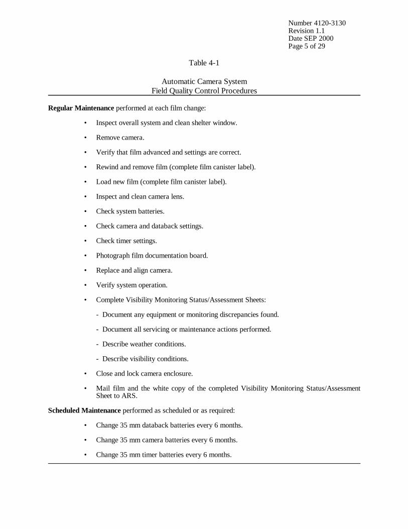
Number 4120-3130 Revision 1.1 Date SEP 2000 Page 5 of 29
Table 4-1
Automatic Camera System Field Quality Control Procedures
Regular Maintenance performed at each film change: • Inspect overall system and clean shelter window. • Remove camera. • Verify that film advanced and settings are correct. • Rewind and remove film (complete film canister label). • Load new film (complete film canister label). • Inspect and clean camera lens. • Check system batteries. • Check camera and databack settings. • Check timer settings. • Photograph film documentation board. • Replace and align camera. • Verify system operation. • Complete Visibility Monitoring Status/Assessment Sheets: - Document any equipment or monitoring discrepancies found. - Document all servicing or maintenance actions performed. - Describe weather conditions. - Describe visibility conditions. • Close and lock camera enclosure. • Mail film and the white copy of the completed Visibility Monitoring Status/Assessment
Sheet to ARS. Scheduled Maintenance performed as scheduled or as required: • Change 35 mm databack batteries every 6 months. • Change 35 mm camera batteries every 6 months. • Change 35 mm timer batteries every 6 months.
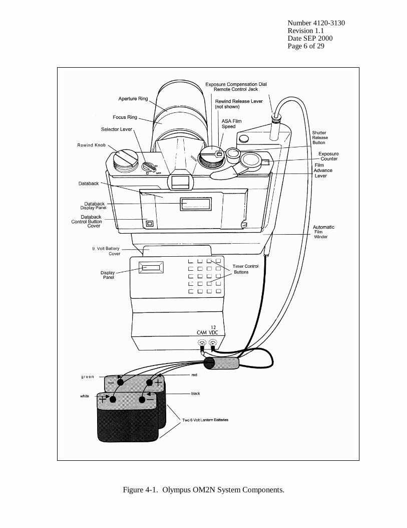
Number 4120-3130 Revision 1.1 Date SEP 2000 Page 6 of 29
Figure 4-1. Olympus OM2N System Components.
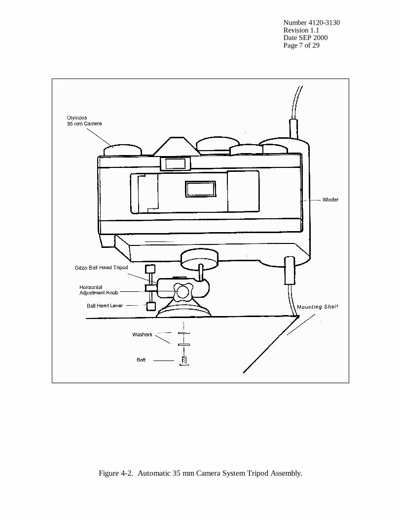
Number 4120-3130 Revision 1.1 Date SEP 2000 Page 7 of 29
Figure 4-2. Automatic 35 mm Camera System Tripod Assembly.
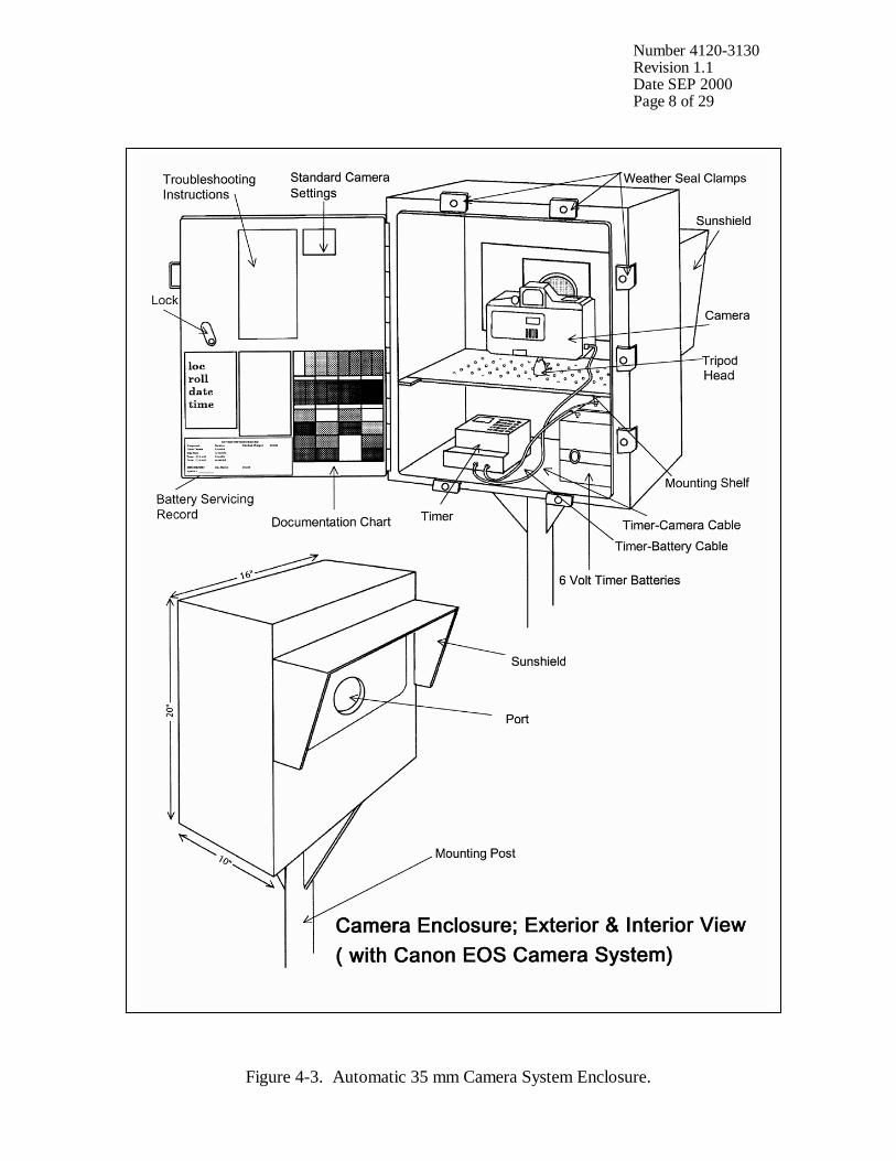
Number 4120-3130 Revision 1.1 Date SEP 2000 Page 8 of 29
Figure 4-3. Automatic 35 mm Camera System Enclosure.
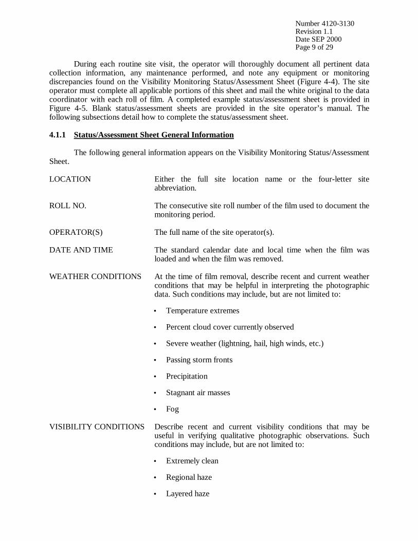
Number 4120-3130 Revision 1.1 Date SEP 2000 Page 9 of 29
During each routine site visit, the operator will thoroughly document all pertinent data collection information, any maintenance performed, and note any equipment or monitoring discrepancies found on the Visibility Monitoring Status/Assessment Sheet (Figure 4-4). The site operator must complete all applicable portions of this sheet and mail the white original to the data coordinator with each roll of film. A completed example status/assessment sheet is provided in Figure 4-5. Blank status/assessment sheets are provided in the site operator’s manual. The following subsections detail how to complete the status/assessment sheet. 4.1.1 Status/Assessment Sheet General Information The following general information appears on the Visibility Monitoring Status/Assessment Sheet. LOCATION Either the full site location name or the four-letter site
abbreviation.
ROLL NO. The consecutive site roll number of the film used to document the monitoring period.
OPERATOR(S) The full name of the site operator(s).
DATE AND TIME The standard calendar date and local time when the film was loaded and when the film was removed.
WEATHER CONDITIONS At the time of film removal, describe recent and current weather conditions that may be helpful in interpreting the photographic data. Such conditions may include, but are not limited to: • Temperature extremes
• Percent cloud cover currently observed
• Severe weather (lightning, hail, high winds, etc.)
• Passing storm fronts
• Precipitation
• Stagnant air masses
• Fog
VISIBILITY CONDITIONS Describe recent and current visibility conditions that may be useful in verifying qualitative photographic observations. Such conditions may include, but are not limited to: • Extremely clean
• Regional haze
• Layered haze
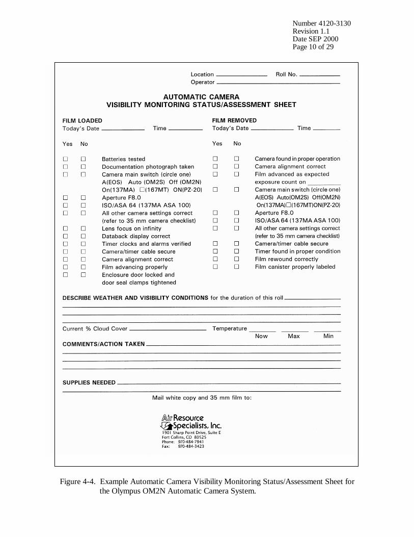
Number 4120-3130 Revision 1.1 Date SEP 2000 Page 10 of 29
Figure 4-4. Example Automatic Camera Visibility Monitoring Status/Assessment Sheet for the Olympus OM2N Automatic Camera System.

Number 4120-3130 Revision 1.1 Date SEP 2000 Page 11 of 29
Figure 4-5. Completed Example of an Automatic Camera Visibility Monitoring Status/Assessment Sheet.
Number 4120-3130 Revision 1.1 Date SEP 2000 Page 12 of 29
VISIBILITY CONDITIONS (continued)
• Plumes
• Severity of haze
• Emission source activity (e.g., nearby forest fires, controlled burns, construction, dusty roads, residential wood burning, etc.)
• Any perceptible odors (e.g., wood smoke)
COMMENTS Describe any equipment or monitoring discrepancies found, troubleshooting or scheduled maintenance performed, and/or corrective actions taken.
SUPPLIES NEEDED List any servicing supplies or documentation materials required for ongoing monitoring.
4.1.2 Status/Assessment Sheet Film Removal Section INSPECT ENCLOSURE Inspect the interior and exterior of the enclosure for damage or
other problems (water leakage, etc.). Inspect the outside of the enclosure window for dirt and clean if necessary.
VERIFY CAMERA ALIGNMENT
The camera alignment must remain constant from one roll to the next. Look through the camera viewfinder to verify that the alignment has remained correct during the monitoring period. If not, note the degree of misalignment and the probable cause.
VERIFY CAMERA/TIMER CABLES
Check the camera/timer and power system (6 V lantern batteries) cable connections. Verify that all cables are secure. Check the integrity of the cables and component connectors. Document any problems, including broken connectors, loose or bare wires, etc. Report any problems promptly to ARS.
REMOVE CAMERA Loosen the camera winder fastening screw. Disconnect the camera body from the automatic winder. The tripod, winder, and winder cabling will remain intact inside the enclosure.
DOCUMENT EXPOSURE NUMBER COUNT
The frame counter indicates if the film advanced properly and how many photographs were taken during the monitoring period. Document whether the film advanced correctly and the observed exposure count number. Report any discrepancies promptly to ARS.
VERIFY SETTINGS Verify all camera and timer settings. Document any settings that are different from those listed on the Visibility Monitoring Status/Assessment Sheet, whether they are site-specific settings or settings made in error. (Site-specific settings may be required at sites where non-standard exposure settings are necessary to ensure quality photographs).Correct any inconsistencies.
Number 4120-3130 Revision 1.1 Date SEP 2000 Page 13 of 29
REWIND FILM Located on the front of the camera body to the right of the lens piece is the rewind release lever. Turn the lever counterclockwise to the “R” position. The film will tear if the rewind lever is not set before attempting to rewind the film. Fold out the REWIND CRANK and wind it in the direction of the arrow. While rewinding, you will feel slight resistance on the crank. IF THE REWIND CRANK IS DIFFICULT TO TURN, check the rewind release lever as described above. When the crank turns freely without resistance, the film has been completely rewound into the cartridge. Do not open the camera back until you are sure that the film has been completely rewound. You cannot damage the film by turning the rewind lever longer than necessary, but the film will be exposed to light and damaged if it is not completely rewound. Open the camera back by pulling up on the rewind knob.
REMOVE FILM AND COMPLETE CANISTER LABEL
Remove exposed film from the camera and place it in the most recently labeled plastic canister. Complete the film canister label by writing in the current date and time. Inspect film compartment for fragments of film. Blow lightly into the compartment to remove film fragments or other particles. DO NOT TOUCH the shutter curtain.
COMPLETE VISIBILITY MONITORING STATUS/ASSESSMENT SHEET
Document: • Any equipment or monitoring discrepancies found.
• All servicing or maintenance actions performed (e.g., date of
battery changes, cables tightened, timer re-programmed, etc.).
• Current and recent weather conditions.
• Current and recent visibility conditions.
4.1.3 Status/Assessment Sheet Film Loading Section LABEL FILM CANISTER
The film canister label identifies the contents of each roll of film. All of the information on the label is permanently logged at ARS when the film is received. Open a box of new, unexposed film and remove the plastic film canister. Fill out a film canister label with the following information and attach it to the outside of the plastic canister: • Monitoring site abbreviation
• Roll number
Number 4120-3130 Revision 1.1 Date SEP 2000 Page 14 of 29
LABEL FILM CANISTER (continued)
• Date and time loaded • Emulsion number and expiration date (information listed on
Kodak film box)
LOAD FILM To open the camera back, pull the REWIND KNOB up. • Remove the film cartridge from the plastic film canister, open
the camera back, and insert the film cartridge into the film chamber, upper flat end first.
• Pull the film leader across the shutter curtain and insert it into the film take-up spool.
• With the camera back open, press the SHUTTER RELEASE button and turn the advance lever to make sure the film has no slack and that its perforations are properly engaged with the sprocket teeth.
• Press the SHUTTER RELEASE button again and turn the advance lever until you are confident that the film is firmly connected to the take-up spool.
• Firmly close the camera back cover.
NOTE: The exposure counter will increment even if the film is loaded correctly. You can assume that the film is loaded correctly ONLY if the rewind shaft rotates when the shutter release is pressed.
Store the empty, labeled plastic film canister inside the camera enclosure until the film is removed.
INSPECT CAMERA LENS Inspect the exterior of the UV filter mounted on the camera lens for any accumulation of dust, dirt, or fingerprints. If accumulation is noted: • Clean the outside of the UV filter with the lens paper and fluid
provided.
• If necessary, unscrew the UV filter and clean the lens and inside surface of the UV filter. Do not remove the lens from the camera body or attempt to clean inner surface of the lens.
• Use lens paper and fluid to clean the viewfinder eyepiece when necessary.
PHOTOGRAPH DOCUMENTATION BOARD
The first exposure on every roll must be of the documentation board which contains the gray scale, color chart, battery servicing record, and pertinent data collection information (Figure 4-6).
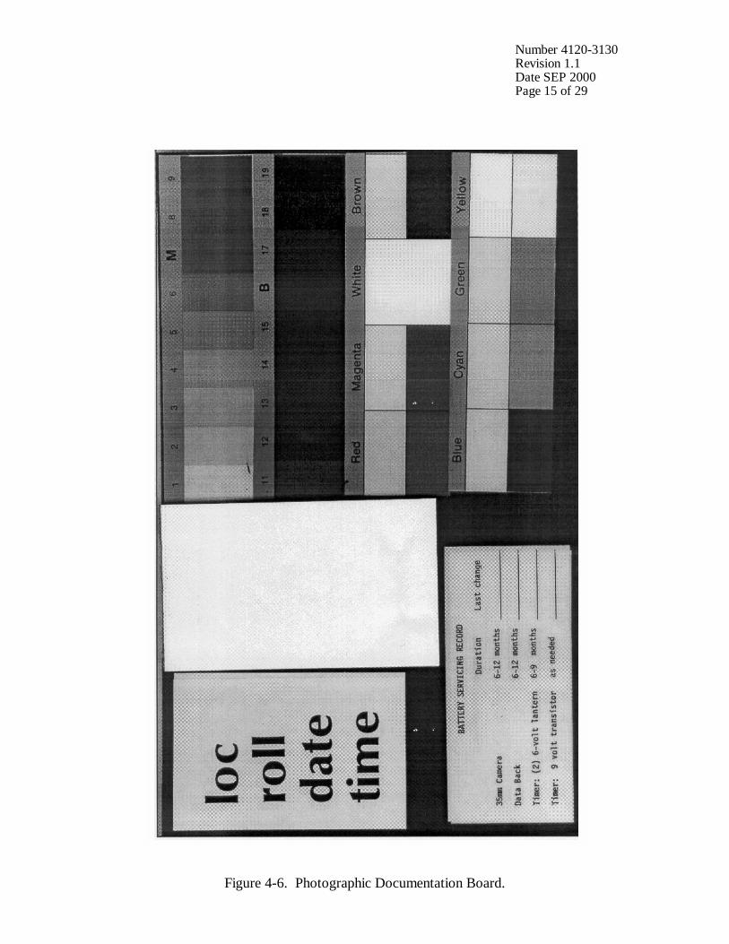
Number 4120-3130 Revision 1.1 Date SEP 2000 Page 15 of 29
Figure 4-6. Photographic Documentation Board.
Number 4120-3130 Revision 1.1 Date SEP 2000 Page 16 of 29
PHOTOGRAPH DOCUMENTATION BOARD (continued)
• Write the following on the note pad provided: - Monitoring site name or abbreviation - Roll number - Date and time • Adjust your position and turn the focus ring to achieve a
close-up, sharply focused photograph.
• Press the SHUTTER BUTTON. Manually turn the advance lever. Verify that the film counter has incremented one frame.
• Reset the focus ring to infinity. The documentation chart should be evenly lit for the photograph. The board is mounted to the enclosed door with Velcro tabs and may be temporarily removed if proper lighting conditions are not possible in its normal position. You may have to shift your position slightly to find a spot where there is no glare from the sun on the board.
CHECK CAMERA BATTERY
Move the selector level to the battery check position. Note the condition of the red lamp: • Continuous Red Light – battery power sufficient • Flashing Light – low (have new batteries on hand) • No Light – drained or installed incorrectly (replace with new
batteries or reinstall) If required, change the camera’s two 1.5 V silver oxide batteries and retest the system. Document all battery changes on the Visibility Monitoring Status/Assessment Sheet and “battery servicing record” portion of the documentation chart. Report any problems promptly to ARS. Camera battery change procedures are described further in Section 4.2.2.
CHECK CAMERA SETTINGS
Verify and change, if necessary, all camera settings for correct automatic operation. Standard settings for the Olympus OM2N are: OM2N Selector Lever OFF Winder Single Exposure Compensation Zero Film Speed ASA 64 Aperture Ring F8 Focus Infinity
Number 4120-3130 Revision 1.1 Date SEP 2000 Page 17 of 29
CHECK CAMERA SETTINGS (continued)
Lighting conditions of the target or vista may require site-specific exposure settings. Setting changes directed by ARS are documented on the enclosure door and in the Automatic 35 mm Camera System User’s Manual provided in the site operator’s manual. Document any settings that are different from those listed above on each Visibility Monitoring Status/Assessment Sheet.
CHECK DATABACK SETTING AND BATTERIES
When using the Recordata Back 3, the databack should be in the “day-time” mode displaying the current day of the month and current time. If the Recordata Back 4 is used, the databack should be in the “year-month-day” mode displaying the current date. Independent of the model used, if the display is flashing or blank, the databack batteries are drained. Replace the batteries only when the film is not loaded. Document all battery changes on the Visibility Monitoring Status/Assessment Sheet and “battery servicing record” portion of the documentation chart. Reset the databack for the current date and time (Recordata Back 3) or current date (Recordata Back 4). Databack setting and programming instructions, as well as battery change procedures are described further in Section 4.2.
CHECK TIMER SETTINGS
Review timer display: • The Paragon EC72D should be in the “RUN” mode
displaying the local time and day-of-week, and the colon should be flashing.
• If the display is incorrect press RUN on the display panel to verify that the timer is in the “RUN” mode. If the time, date, or display is still incorrect, reset the timer.
• If the timer display is blank, the timer battery wiring may be incorrect or the battery power may be insufficient.
Review the programmed timer events: • Press PRG then C1 to select Channel 1 for review. • Press E repeatedly to review each event. In normal operation,
Event 1 (E:01) is 0900, Event 2 (E:02) is 1200, and Event 3 (E:03) is 1500. The remaining events are not programmed.
If events are incorrect, reprogram the timer clock and timer events. Timer setting and programming instructions are provided in Section 4.2.3. Press RUN when finished reviewing or changing events to return the timer to the “RUN” mode.
Number 4120-3130 Revision 1.1 Date SEP 2000 Page 18 of 29
CHECK TIMER SETTINGS (continued)
NOTE: If a photograph was scheduled to occur while you were reviewing or programming information, the photograph was not taken.
REPLACE AND ALIGN CAMERA
It is important for the alignment to be consistent from one roll to the next. • Mount the camera on the tripod head.
• Securely reconnect the camera/timer cable to the timer at the
timer jack.
• Look through the viewfinder and align the camera on the vista to be photographed.
• Verify that the alignment matches the previous alignment, the horizon is level, the enclosure port does not appear in the frame, and the lens focus is on infinity. (A 3” x 5” site alignment photograph is provided in the camera enclosure for reference).
• Firmly tighten all levers on the tripod head and recheck the alignment.
If weather conditions obscure the target area, use foreground features to judge alignment. Visit the site again when the weather clears to recheck the alignment.
VERIFY CAMERA/TIMER CABLES AND FILM ADVANCE
Verify the camera/timer and power system (6 V lantern batteries) cable connections. Test the timer and battery cable connections: • The timer must be in the “RUN” mode, with the time and
day-of-week displayed and colon flashing.
• Press C1; the camera should fire. The timer automatically returns to the “RUN” mode.
If the camera does not fire, the camera/timer wiring is incorrect or the battery power to the timer is insufficient. Test the camera/timer cable connection: • Gently shake the camera/timer cable leading into the camera
remote jack. If the camera fires, an electrical short may exist in a portion of the cable jack(s).
Document any discrepancies and/or corrective actions taken. Report any problems promptly to ARS.

Number 4120-3130 Revision 1.1 Date SEP 2000 Page 19 of 29
DOCUMENT FINDINGS AND ACTIONS PERFORMED
Document any servicing or maintenance actions performed during the film loading process. Place the completed Visibility Monitoring Status/Assessment Sheet (yellow copy) in the Site Operator’s Manual for Automatic Visibility Monitoring Camera Systems.
CLOSE AND SECURE ENCLOSURE
Place the Site Operator’s Manual for Automatic Visibility Monitoring Camera Systems inside the camera enclosure for future reference. Close and lock the camera enclosure door. Tighten all door seal clamps and padlock the enclosure door hasp.
4.1.4 Mailing the Film and Completed Status/Assessment Sheet Place the original (white) copy of the Visibility Monitoring Status/Assessment Sheet and corresponding roll of film in a padded mailing envelope. Mail both the film and the Visibility Monitoring Status/Assessment Sheet immediately to: Air Resource Specialists, Inc. 1901 Sharp Point Drive, Suite E Fort Collins, CO 80525 Attention: Photographic Data Coordinator Call ARS immediately if any inconsistencies were noted or if any questions arise. Many problems can be resolved through telephone consultation. ARS may be reached at the following telephone numbers: Telephone: 970/484-7941 Fax: 970/484-3423 Detailed troubleshooting procedures to assist with telephone-directed problem resolution are presented in TI 4120-3330, Troubleshooting and Emergency Maintenance Procedures for 35 mm Automatic Camera System - Olympus OM2N. 4.2 SCHEDULED MAINTENANCE Proper film storage and periodic preventive maintenance will help to ensure consistent, high quality data collection. Preventive maintenance servicing visits are performed as scheduled or required by the data coordinator. Scheduled maintenance normally consists of:
• Camera battery changes (every six months)
• Databack battery changes (every six months)
• Timer battery changes (every six months)
Number 4120-3130 Revision 1.1 Date SEP 2000 Page 20 of 29
Replacement camera and timer batteries are provided by ARS with each film shipment (every six months). Replacement databack batteries are provided annually. Additional batteries will be provided as needed or as requested by the site operator. Test all batteries with a voltmeter before placing them in the system component. Verify all timer or camera battery malfunctions by testing removed component batteries with a voltmeter. Additional servicing tasks identified by the data coordinator may include:
• Camera, databack, and timer configuration checks or changes
• Camera alignment changes
• Revision of data collection procedures All scheduled maintenance requested by the data coordinator or performed by the site operator must be thoroughly documented on the Visibility Monitoring Status/Assessment Sheet and in the site-specific Quality Assurance Database. Any equipment malfunctions or data collection discrepancies observed during a scheduled maintenance visit should be reported to ARS immediately. The following subsections further describe proper methods for film storage, scheduled maintenance procedures, and corresponding servicing documentation. Troubleshooting and emergency maintenance procedures for the Olympus OM2N are provided in TI 4120-3330, Troubleshooting and Emergency Maintenance Procedures for 35 mm Automatic Camera System - Olympus OM2N. 4.2.1 Film and Film Storage Only Kodachrome 64 slide film provided by ARS should be loaded into the visibility monitoring camera unless otherwise directed. Each roll of film has an emulsion number and expiration date. This information must be documented on the canister label of each exposed film roll (see Section 4.1.3). Photographic film is sensitive to heat and moisture. These elements can affect the film, altering both the processed photographs and the data analysis. For example, film subjected to heat often has a pink or purple cast while film subjected to moisture does not process consistently. To ensure proper film storage, keep the film inside a Ziploc bag with desiccant and place the bag inside the clearly labeled film storage box. The box should be stored in a freezer, refrigerator, or cool (less than 70°F), dry location. If stored in a freezer, allow film to thaw at room temperature for at least two hours before loading it in the camera. 4.2.2 Changing System Batteries CAMERA BATTERY CHANGE
The Olympus OM2N camera runs on two 1.5 V silver oxide batteries. The batteries should be replaced every six months or as directed by the data coordinator.
Number 4120-3130 Revision 1.1 Date SEP 2000 Page 21 of 29
CAMERA BATTERY CHANGE (continued)
• The battery compartment is on the bottom of the camera. Unscrew the cap with a coin.
• Remove the new batteries from their packaging and test and record the voltage. Each new battery should measure at least 1.5 volts.
• Insert the two new 1.5 V silver oxide batteries with the (+) facing you.
• Always replace batteries as a pair.
• Replace the compartment cap and tighten.
• After changing batteries, check them as described in Section 4.1.3.
DATABACK BATTERY CHANGE
The Olympus OM2N Recordata Back 3 or 4 run on two 1.5 V silver oxide batteries. The databack batteries should be replaced every six months, or as required by the data coordinator. Be sure to replace the batteries only when film is not loaded. • Open the camera back by pulling up on the rewind knob
crank.
• Insert a coin edge or other suitable object into the screwhead located in the center of the battery compartment cover on the inside of the databack.
• Turn the screw counterclockwise and open the cover. Remove the used batteries. Measure and record the voltage of the used batteries.
• Remove the new batteries from their packaging and test and record the voltage. The new batteries should measure approximately 1.5 volts.
• Insert two 1.5 V silver oxide batteries with their plus (+) marks facing upward, otherwise the databack will not function.
• Replace the cover.
• Check the display and reset the databack for the current date and time as described in Section 4.1.3.
TIMER BATTERY VERIFICATION AND CHANGES
The Paragon EC72D timer runs on two 6 V lantern batteries. Both 6 V lantern batteries should be replaced biannually or as directed by the data coordinator.
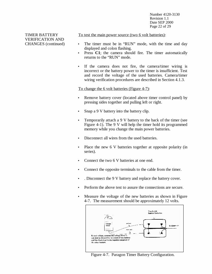
Number 4120-3130 Revision 1.1 Date SEP 2000 Page 22 of 29
TIMER BATTERY VERIFICATION AND CHANGES (continued)
To test the main power source (two 6 volt batteries): • The timer must be in “RUN” mode, with the time and day
displayed and colon flashing. • Press C1; the camera should fire. The timer automatically
returns to the “RUN” mode.
• If the camera does not fire, the camera/timer wiring is incorrect or the battery power to the timer is insufficient. Test and record the voltage of the used batteries. Camera/timer wiring verification procedures are described in Section 4.1.3.
To change the 6 volt batteries (Figure 4-7): • Remove battery cover (located above timer control panel) by
pressing sides together and pulling left or right.
• Snap a 9 V battery into the battery clip.
• Temporarily attach a 9 V battery to the back of the timer (see Figure 4-1). The 9 V will help the timer hold its programmed memory while you change the main power batteries.
• Disconnect all wires from the used batteries.
• Place the new 6 V batteries together at opposite polarity (in series).
• Connect the two 6 V batteries at one end.
• Connect the opposite terminals to the cable from the timer.
• . Disconnect the 9 V battery and replace the battery cover.
• Perform the above test to assure the connections are secure.
• Measure the voltage of the new batteries as shown in Figure
4-7. The measurement should be approximately 12 volts.
Figure 4-7. Paragon Timer Battery Configuration.
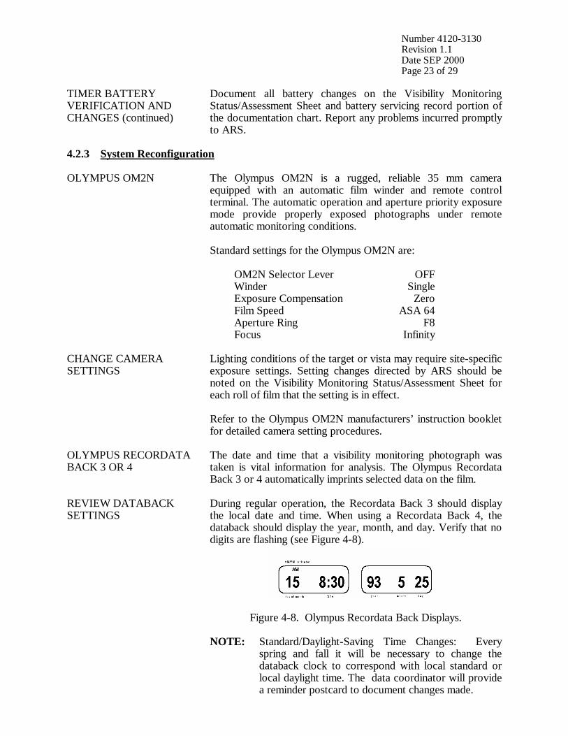
Number 4120-3130 Revision 1.1 Date SEP 2000 Page 23 of 29
TIMER BATTERY VERIFICATION AND CHANGES (continued)
Document all battery changes on the Visibility Monitoring Status/Assessment Sheet and battery servicing record portion of the documentation chart. Report any problems incurred promptly to ARS.
4.2.3 System Reconfiguration OLYMPUS OM2N The Olympus OM2N is a rugged, reliable 35 mm camera
equipped with an automatic film winder and remote control terminal. The automatic operation and aperture priority exposure mode provide properly exposed photographs under remote automatic monitoring conditions. Standard settings for the Olympus OM2N are: OM2N Selector Lever OFF Winder Single Exposure Compensation Zero Film Speed ASA 64 Aperture Ring F8 Focus Infinity
CHANGE CAMERA SETTINGS
Lighting conditions of the target or vista may require site-specific exposure settings. Setting changes directed by ARS should be noted on the Visibility Monitoring Status/Assessment Sheet for each roll of film that the setting is in effect. Refer to the Olympus OM2N manufacturers’ instruction booklet for detailed camera setting procedures.
OLYMPUS RECORDATA BACK 3 OR 4
The date and time that a visibility monitoring photograph was taken is vital information for analysis. The Olympus Recordata Back 3 or 4 automatically imprints selected data on the film.
REVIEW DATABACK SETTINGS
During regular operation, the Recordata Back 3 should display the local date and time. When using a Recordata Back 4, the databack should display the year, month, and day. Verify that no digits are flashing (see Figure 4-8).
Figure 4-8. Olympus Recordata Back Displays.
NOTE: Standard/Daylight-Saving Time Changes: Every
spring and fall it will be necessary to change the databack clock to correspond with local standard or local daylight time. The data coordinator will provide a reminder postcard to document changes made.
Number 4120-3130 Revision 1.1 Date SEP 2000 Page 24 of 29
REVIEW DATABACK SETTINGS (continued)
To set the Recordata Back 3: • Open the control button cover on the left side of the databack.
A fingernail catch is located at the bottom of the cover.
• Press the TIME SET MODE button (the second button from the top) until the flashing SET indicator in the top left corner is displayed.
• Press the SELECT button until the correct year-month-day format is displayed. The “DAY” will be flashing. Press the SET button until the correct day is displayed. Constant pressure on the set button will rapidly advance the numbers.
• Press the SELECT button again and the “MONTH” display will flash. Press the SET button until the correct month is displayed.
• Press the SELECT button again and the “YEAR” display will flash. Press the SET button until the correct year is displayed.
• Press the SELECT button again and the “TIME” format will be displayed. Again press the SELECT button and the “MINUTE” display will flash. Press the SET button until the correct minute is displayed.
• Press the SELECT button and the “HOUR” display will flash. Press the SET button until the correct hour is displayed.
NOTE: The databack has an “AM” and “PM” setting. Be certain the correct indicator is displayed. Return to the correct operating mode by pressing the TIME SET mode button until ONLY the day, time, and AM or PM are displayed and the colon (:) between the hour and minutes is flashing. To set the Recordata Back 4: • Open the control button cover on the left side of the databack.
A fingernail catch is located at the bottom of the cover.
• Press the SELECT button until the correct year-month-day format is displayed. The “DAY” will be flashing. Press the SET button until the correct day is displayed. Constant pressure on the set button will rapidly advance the numbers.
• Press the SELECT button again and the “MONTH” display will
flash. Press the SET button until the correct month is displayed.
• Press the SELECT button again and the “YEAR” display will flash. Press the SET button until the correct year is displayed.
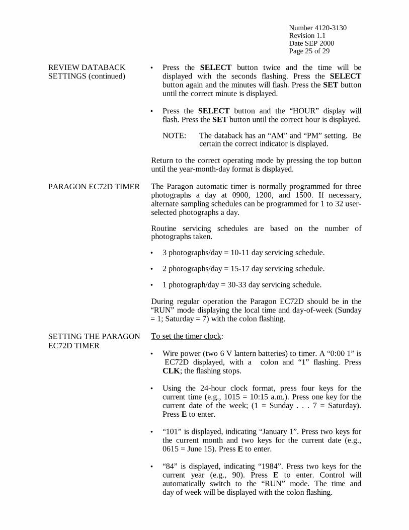
Number 4120-3130 Revision 1.1 Date SEP 2000 Page 25 of 29
REVIEW DATABACK SETTINGS (continued)
• Press the SELECT button twice and the time will be displayed with the seconds flashing. Press the SELECT button again and the minutes will flash. Press the SET button until the correct minute is displayed.
• Press the SELECT button and the “HOUR” display will flash. Press the SET button until the correct hour is displayed.
NOTE: The databack has an “AM” and “PM” setting. Be certain the correct indicator is displayed. Return to the correct operating mode by pressing the top button until the year-month-day format is displayed.
PARAGON EC72D TIMER The Paragon automatic timer is normally programmed for three photographs a day at 0900, 1200, and 1500. If necessary, alternate sampling schedules can be programmed for 1 to 32 user-selected photographs a day. Routine servicing schedules are based on the number of photographs taken. • 3 photographs/day = 10-11 day servicing schedule. • 2 photographs/day = 15-17 day servicing schedule. • 1 photograph/day = 30-33 day servicing schedule. During regular operation the Paragon EC72D should be in the “RUN” mode displaying the local time and day-of-week (Sunday = 1; Saturday = 7) with the colon flashing.
SETTING THE PARAGON EC72D TIMER
To set the timer clock: • Wire power (two 6 V lantern batteries) to timer. A “0:00 1” is
EC72D displayed, with a colon and “1” flashing. Press CLK; the flashing stops.
• Using the 24-hour clock format, press four keys for the current time (e.g., 1015 = 10:15 a.m.). Press one key for the current date of the week; (1 = Sunday . . . 7 = Saturday). Press E to enter.
• “101” is displayed, indicating “January 1”. Press two keys for the current month and two keys for the current date (e.g., 0615 = June 15). Press E to enter.
• “84” is displayed, indicating “1984”. Press two keys for the current year (e.g., 90). Press E to enter. Control will automatically switch to the “RUN” mode. The time and day of week will be displayed with the colon flashing.
Number 4120-3130 Revision 1.1 Date SEP 2000 Page 26 of 29
SETTING THE PARAGON EC72D TIMER (continued)
To program times for photographs to be taken: • Press PRG to enter “program” mode.
• Press C1 to select Channel 1 for programming; “E:01” (for
the first event) is displayed.
• Press four keys for the time the first photograph should be taken (e.g., 0900 for 9:00 a.m.). Press 0 to program the event to occur daily. Press E to enter the event into memory.
• The next event slot will be displayed (e.g., E:02). Repeat the
step immediately above for each time of the day a photograph should be taken.
• Press RUN to return to “RUN” mode after all selected photograph times are programmed.
Procedures to review programmed timer events are provided in Section 4.1.3. NOTE: If more than 16 photographs per day are desired,
Channel 2 may be used to program up to 16 additional events provided the Channel 2 output terminals have also been wired to the camera.
SITE-SPECIFIC CAMERA ALIGNMENT
Correct alignment of the camera is extremely important. Each photograph is compared to others of the same view during analysis. Therefore, alignment must remain constant from one roll of film to the next. A 3” x 5” site alignment photograph is provided for your reference in the camera enclosure. Alignment changes or adjustments may be necessary when: • Selected features are not properly framed in the view, and/or
• Exposure discrepancies result from intruding foreground or
backlit features. Any alignment change directed by ARS should be fully documented on the Visibility Monitoring Status/Assessment Sheet.
VERIFY CAMERA ALIGNMENT
Look through the viewfinder to verify the following: • The alignment matches the referenced site-specific alignment
photograph.
• The horizon is level.
• The vista is framed correctly.
Number 4120-3130 Revision 1.1 Date SEP 2000 Page 27 of 29
VERIFY CAMERA ALIGNMENT (continued)
• The sunshield and port are not visible in the viewfinder.
• The lens focus is on infinity. Document any misalignment found and assess probable cause on the Visibility Monitoring Status/Assessment Sheet. If weather conditions obscure the target area, use foreground features to judge alignment. Visit the site again when the weather clears to recheck the alignment. Procedures to ensure ongoing alignment are provided in TI 4120-3330, Troubleshooting and Emergency Maintenance Procedures for 35 mm Automatic Camera System - Olympus OM2N.
4.2.4 On-Site Data Control During each routine site visit, the operator documents maintenance performed and notes all discrepancies on the Visibility Monitoring Status/Assessment Sheet. The completed original (white copy) is mailed with each roll of film. A copy (yellow) is kept in the Site Operator’s Manual for Automatic Visibility Monitoring Camera Systems. If discrepancies or operator comments on the sheets indicate that further action is necessary, immediate corrective action is taken. Throughout the monitoring effort, ARS and site operators maintain close personal communications. Operators are encouraged to call or notify ARS if they have questions or problems. Ongoing review of film and site operator documentation often initiates corrective actions. Common data collection problems identified include:
• Roll number discrepancies
• Missing or improperly exposed documentation chart photographs
• Improper film loading or rewinding
• Late film changes
• Improper camera alignment
• Incorrect camera settings
• Weak or missing databack imprinting
• Incorrect timer settings
• Incomplete Visibility Monitoring Status/Assessment Sheet documentation

Number 4120-3130 Revision 1.1 Date SEP 2000 Page 28 of 29
All scheduled maintenance requested by the data coordinator or performed by the site operator must be thoroughly documented on the Visibility Monitoring Status/Assessment Sheet and in the site-specific Quality Assurance Database. If necessary, a Photographic Monitoring Network Quality Assessment Log (Figure 4-9) is mailed to the site to further document corrective actions taken. The site operator documents the date of correction and what was done, and returns a carbon copy of the log to ARS. Problems and equipment malfunctions requiring extensive troubleshooting and/or maintenance are fully described in TI 4120-3330.

Number 4120-3130 Revision 1.1 Date SEP 2000 Page 29 of 29
PHOTOGRAPHIC MONITORING NETWORK QUALITY ASSESSMENT LOG
Site: _________________________ Date: ________________________________ _________________________ Operator: _____________________ From: ________________________ PROBLEM DESCRIPTION: ___________________________________________________________________________ ___________________________________________________________________________ ___________________________________________________________________________ ___________________________________________________________________________ ACTION REQUEST: ___________________________________________________________________________ ___________________________________________________________________________ ___________________________________________________________________________ ___________________________________________________________________________ ___________________________________________________________________________ ___________________________________________________________________________ ___________________________________________________________________________ ___________________________________________________________________________ CORRECTIVE ACTION TAKEN (to be completed by site operator): ___________________________________________________________________________ ___________________________________________________________________________ ___________________________________________________________________________ ___________________________________________________________________________ ___________________________________________________________________________ ___________________________________________________________________________ Date: __________________________ Operator: ________________________________
Return Yellow Copy To: White - Original, site copy Yellow - return to ARS Pink - ARS retain
Figure 4-9. Photographic Monitoring Network Quality Assessment Log.
QUALITY ASSURANCE/QUALITY CONTROL DOCUMENTATION SERIES TITLE
ROUTINE SITE OPERATOR MAINTENANCE PROCEDURES FOR 35 MM AUTOMATIC CAMERA SYSTEM – PENTAX PZ-20
TYPE
TECHNICAL INSTRUCTION
NUMBER
4120-3140
DATE
JULY 1994
AUTHORIZATIONS
TITLE NAME SIGNATURE
ORIGINATOR Karen K. Rosener
PROJECT MANAGER James H. Wagner
PROGRAM MANAGER David L. Dietrich
QA MANAGER Gloria S. Mercer
OTHER
REVISION HISTORY
REVISION NO.
CHANGE DESCRIPTION DATE AUTHORIZATIONS
Reviewed; no changes necessary. July 1995 1.0 Revised illustrations and forms. June 1996
Reviewed; no changes necessary. June 1997
Reviewed; no changes necessary. June 1998
Reviewed; no changes necessary. June 1999
Reviewed; no changes necessary. June 2000
1.1 Delete references to 9v battery in timer. September 2000
Reviewed; no changes necessary. September 2001
-- continued --
QUALITY ASSURANCE/QUALITY CONTROL DOCUMENTATION SERIES TITLE
ROUTINE SITE OPERATOR MAINTENANCE PROCEDURES FOR 35 MM AUTOMATIC CAMERA SYSTEM – PENTAX PZ-20
TYPE
TECHNICAL INSTRUCTION
NUMBER
4120-3140
DATE
JULY 1994
AUTHORIZATIONS
TITLE NAME SIGNATURE
ORIGINATOR Karen K. Rosener
PROJECT MANAGER James H. Wagner
PROGRAM MANAGER David L. Dietrich
QA MANAGER Gloria S. Mercer
OTHER
REVISION HISTORY
REVISION NO.
CHANGE DESCRIPTION DATE AUTHORIZATIONS
Reviewed; no changes necessary. September 2002
Number 4120-3140 Revision 1.1 Date SEP 2000 Page i of ii
TABLE OF CONTENTS Section Page 1.0 PURPOSE AND APPLICABILITY 1 2.0 RESPONSIBILITIES 1 2.1 Project Manager 1 2.2 Field Specialist 1 2.3 Data Coordinator 2 2.4 Site Operator 2 3.0 REQUIRED EQUIPMENT AND MATERIALS 2 3.1 Site Visit Equipment 2 3.2 Inventory 4 4.0 METHODS 4 4.1 Routine Servicing 4 4.1.1 Status/Assessment Sheet General Information 9 4.1.2 Status/Assessment Sheet Film Removal Section 12 4.1.3 Status/Assessment Sheet Film Loading Section 13 4.1.4 Mailing the Film and Completed Status/Assessment Sheet 19 4.2 Scheduled Maintenance 19 4.2.1 Film and Film Storage 20 4.2.2 Changing System Batteries 21 4.2.3 System Reconfiguration 23 4.2.4 On-Site Data Control 28
LIST OF FIGURES Figure Page 4-1 Pentax PZ-20 System Components 6 4-2 Automatic 35 mm Camera System Tripod Assembly 7 4-3 Automatic 35 mm Camera System Enclosure 8 4-4 Example Automatic Camera Visibility Monitoring Status/Assessment Sheet for the Pentax PZ-20 Automatic Camera System 10
Number 4120-3140 Revision 1.1 Date SEP 2000 Page ii of ii
LIST OF FIGURES (CONTINUED) Figure Page 4-5 Completed Example of an Automatic Camera Visibility Monitoring Status/ Assessment Sheet 11 4-6 Photographic Documentation Board 16 4-7 Paragon Timer Battery Configuration 23 4-8 Pentax PZ-20 Display Panel 24 4-9 Pentax Data Back FE Displays 24 4-10 Photographic Monitoring Network Quality Assessment Log 29
LIST OF TABLES Table Page 4-1 Automatic Camera System Field Quality Control Procedures 5
Number 4120-3140 Revision 1.1 Date SEP 2000 Page 1 of 29
1.0 PURPOSE AND APPLICABILITY The purpose of routine site operator maintenance is to assure quality data capture and minimize data loss by performing and documenting scheduled operational checks and preventive maintenance. This technical instruction (TI) describes the steps of a routine site visit, scheduled maintenance, and on-site data control for the Pentax PZ-20 35 mm camera system. Routine servicing schedules are based on the number of photographs taken each day. Assuming a three-photograph per day schedule, site operators service the camera approximately every 10 days to change film, check the performance of the camera system, clean system components, and perform troubleshooting and/or emergency maintenance as required. Preventive maintenance site visits are performed every six months or as required by the data coordinator. The effective performance and documentation of each of these tasks is the key to quality data collection and minimal data loss. Site operators should be fully trained and supplied with a Site Operator’s Manual for Automatic Visibility Monitoring Camera Systems that contains detailed routine site operator maintenance and troubleshooting procedures for the specific camera monitoring system(s) located at the site. Additional manufacturer instruction booklets and a supply of Visibility Monitoring Status/Assessment Sheets are also provided. Close personal communications should be maintained between Air Resource Specialists, Inc. (ARS) and site operators throughout the monitoring effort. Operators are encouraged to call or notify ARS if they have any questions or problems. Many problems can be fully resolved over the telephone. 2.0 RESPONSIBILITIES 2.1 PROJECT MANAGER The project manager shall coordinate with the site operator, his/her supervisor, field specialist, and data coordinator concerning the schedule and requirements for routine maintenance. 2.2 FIELD SPECIALIST The field specialist shall:
• Coordinate with the project manager, the site operator, his/her supervisor, and data coordinator concerning the schedule and requirements for routine maintenance.
• Train the site operator in all phases of camera system maintenance.
• Provide technical support to the site operator via telephone to assure high quality site
visits.
• Resolve problems reported by the site operator.
• Document all technical support provided to the site operator.
Number 4120-3140 Revision 1.1 Date SEP 2000 Page 2 of 29
2.3 DATA COORDINATOR The data coordinator shall:
• Coordinate with the project manager, the site operator, his/her supervisor, and field specialist concerning the schedule and requirements for routine maintenance.
• Verify that scheduled visits are performed and notify the site operator if he/she fails to
make a scheduled visit.
• Review all site documentation completed by the site operator for accuracy and completeness. File all documentation and correspondence.
• Resolve problems reported by the site operator.
• Enter the results of all performed procedures into the site-specific Quality Assurance
Database.
• Supply the site operator with all necessary monitoring supplies.
• Coordinate the replacement and repair of all malfunctioning units.
• Document all capital instrumentation changes and maintain inventory records in the ARS Purchase Order/Inventory Database.
2.4 SITE OPERATOR The site operator shall:
• Coordinate with his/her supervisor, the project manager, data coordinator, and field specialist concerning the schedule and requirements for routine maintenance.
• Schedule regular site maintenance visits and perform all procedures described in this
TI.
• Thoroughly document all procedures on the Visibility Monitoring Status/Assessment Sheet; mail the white copy of the completed sheet to the data coordinator and maintain an on-site file of the yellow copy.
• Immediately report any noted inconsistencies to the data coordinator or field specialist.
3.0 REQUIRED EQUIPMENT AND MATERIALS 3.1 SITE VISIT EQUIPMENT Equipment and materials generally required to support a routine site visit or scheduled maintenance include:
• Medium and small flat-blade screwdriver
• Small Phillips-head screwdriver
Number 4120-3140 Revision 1.1 Date SEP 2000 Page 3 of 29
• Medium adjustable wrench
• Keys for enclosure and padlocks
• Voltmeter
• Backup camera, databack, and timer batteries: - Pentax PZ-20: - one 6 V lithium battery - Pentax Data Back FE: - one 3 V lithium battery - Paragon EC72D: - two 6 V lantern batteries
• Watch
• Lens cleaner and lens paper
• Site Operator’s Manual for Automatic Visibility Monitoring Camera Systems containing:
- SOP 4120, Automatic Camera System Maintenance (IMPROVE Protocol) - TI 4120-3140, Routine Site Operator Maintenance Procedures for 35 mm
Automatic Camera System - Pentax PZ-20 - TI 4120-3340, Troubleshooting and Emergency Maintenance Procedures for
35 mm Automatic Camera System - Pentax PZ-20 - Automatic 35 mm Camera System User’s Manual - Manufacturers’ instruction booklets - Visibility Monitoring Status/Assessment Sheets - Film canister labels
• Pen or pencil
• Grease pencil
• Supplemental visibility monitoring film
• Padded mailing envelopes
Number 4120-3140 Revision 1.1 Date SEP 2000 Page 4 of 29
3.2 INVENTORY It is imperative that any capital instrumentation changes made as a result of routine maintenance be thoroughly documented. Specific model and serial numbers of the exchanged enclosure, camera body, lens, databack, and/or automatic timer should be documented for future reference by the data coordinator in the site-specific Quality Assurance Database and ARS Purchase Order/Inventory Database. Any on-site changes made should be documented by the site operator on a Visibility Monitoring Status/Assessment Sheet. Capital equipment exchange procedures are discussed in TI 4120-3340, Troubleshooting and Emergency Maintenance Procedures for 35 mm Automatic Camera System - Pentax PZ-20. 4.0 METHODS This section includes two (2) major subsections: 4.1 Routine Servicing 4.2 Scheduled Maintenance Detailed procedures described in these subsections are summarized in Table 4-1. A variety of automatic camera monitoring configurations exist. Specific equipment servicing requirements for each site will vary with the system configuration. All procedures described in this TI refer to the Pentax PZ-20 35 mm camera and Paragon EC72D automatic timer. Routine servicing procedures are summarized in the Automatic 35 mm Camera System User’s Manual for the Pentax PZ-20 System, provided in the site operator’s manual. Detailed schematic diagrams of the Pentax PZ-20 35 mm camera system and associated components are provided in Figures 4-1 through 4-3. The following manufacturers’ instruction booklets are provided for reference in the Site Operator’s Manual for Automatic Visibility Monitoring Camera Systems:
• Pentax PZ-20
• Pentax Data Back FE
• Paragon EC72, EC72D, and EC72E Resolution of problems noted during routine servicing or scheduled maintenance can be more fully investigated by following the troubleshooting and emergency maintenance procedures defined in TI 4120-3340. 4.1 ROUTINE SERVICING Routine servicing schedules are based on the number of photographs taken each day. A common monitoring schedule includes taking three photographs a day at 0900, 1200, and 1500. Assuming this schedule, site operators service the camera approximately every 10 days. Alternate monitoring schedules are discussed in Section 4.2.3. Supplemental film and backup batteries should be on hand whenever the site is visited, this will minimize servicing time and data loss should a problem occur or be detected during servicing.

Number 4120-3140 Revision 1.1 Date SEP 2000 Page 5 of 29
Table 4-1
Automatic Camera System Field Quality Control Procedures
Regular Maintenance performed at each film change: • Inspect overall system and clean shelter window. • Remove camera. • Verify that film advanced and settings are correct. • Rewind and remove film (complete film canister label). • Load new film (complete film canister label). • Inspect and clean camera lens. • Check system batteries. • Check camera and databack settings. • Check timer settings. • Photograph film documentation board. • Replace and align camera. • Verify system operation. • Complete Visibility Monitoring Status/Assessment Sheets: - Document any equipment or monitoring discrepancies found. - Document all servicing or maintenance actions performed. - Describe weather conditions. - Describe visibility conditions. • Close and lock camera enclosure. • Mail film and the white copy of the completed Visibility Monitoring Status/Assessment
Sheet to ARS. Scheduled Maintenance performed as scheduled or as required: • Change 35 mm databack batteries annually. • Change 35 mm camera batteries every 6 months. • Change 35 mm timer batteries every 6 months.

Number 4120-3140 Revision 1.1 Date SEP 2000 Page 6 of 29
Figure 4-1. Pentax PZ-20 System Components.
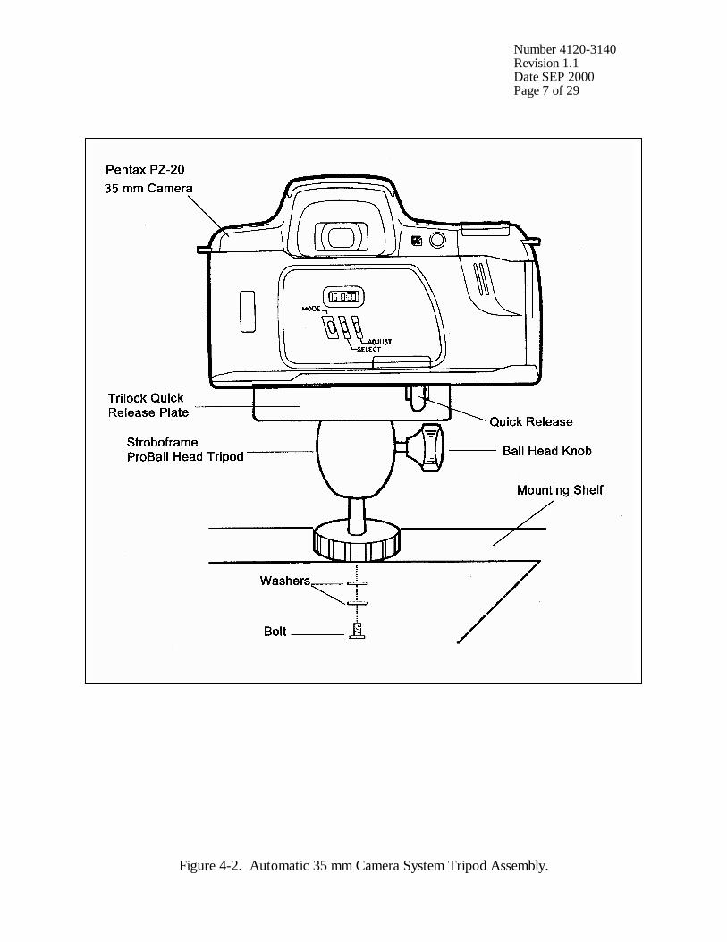
Number 4120-3140 Revision 1.1 Date SEP 2000 Page 7 of 29
Figure 4-2. Automatic 35 mm Camera System Tripod Assembly.

Number 4120-3140 Revision 1.1 Date SEP 2000 Page 8 of 29
Figure 4-3. Automatic 35 mm Camera System Enclosure.

Number 4120-3140 Revision 1.1 Date SEP 2000 Page 9 of 29
During each routine site visit, the operator will thoroughly document all pertinent data collection information, any maintenance performed, and note any equipment or monitoring discrepancies found on the Visibility Monitoring Status/Assessment Sheet (Figure 4-4). The site operator must complete all applicable portions of this sheet and mail the white original to the data coordinator with each roll of film. A completed example status/assessment sheet is provided in Figure 4-5. Blank status/assessment sheets are provided in the site operator’s manual. The following subsections detail how to complete the status/assessment sheet. 4.1.1 Status/Assessment Sheet General Information The following general information appears on the Visibility Monitoring Status/Assessment Sheet. LOCATION Either the full site location name or the four-letter site
abbreviation.
ROLL NO. The consecutive site roll number of the film used to document the monitoring period.
OPERATOR(S) The full name of the site operator(s).
DATE AND TIME The standard calendar date and local time when the film was loaded and when the film was removed.
WEATHER CONDITIONS At the time of film removal, describe recent and current weather conditions that may be helpful in interpreting the photographic data. Such conditions may include, but are not limited to: • Temperature extremes
• Percent cloud cover currently observed
• Severe weather (lightning, hail, high winds, etc.)
• Passing storm fronts
• Precipitation
• Stagnant air masses
• Fog
VISIBILITY CONDITIONS Describe recent and current visibility conditions that may be useful in verifying qualitative photographic observations. Such conditions may include, but are not limited to: • Extremely clean
• Regional haze
• Layered haze

Number 4120-3140 Revision 1.1 Date SEP 2000 Page 10 of 29
Figure 4-4. Example Automatic Camera Visibility Monitoring Status/Assessment Sheet for the Pentax PZ-20 Automatic Camera System.
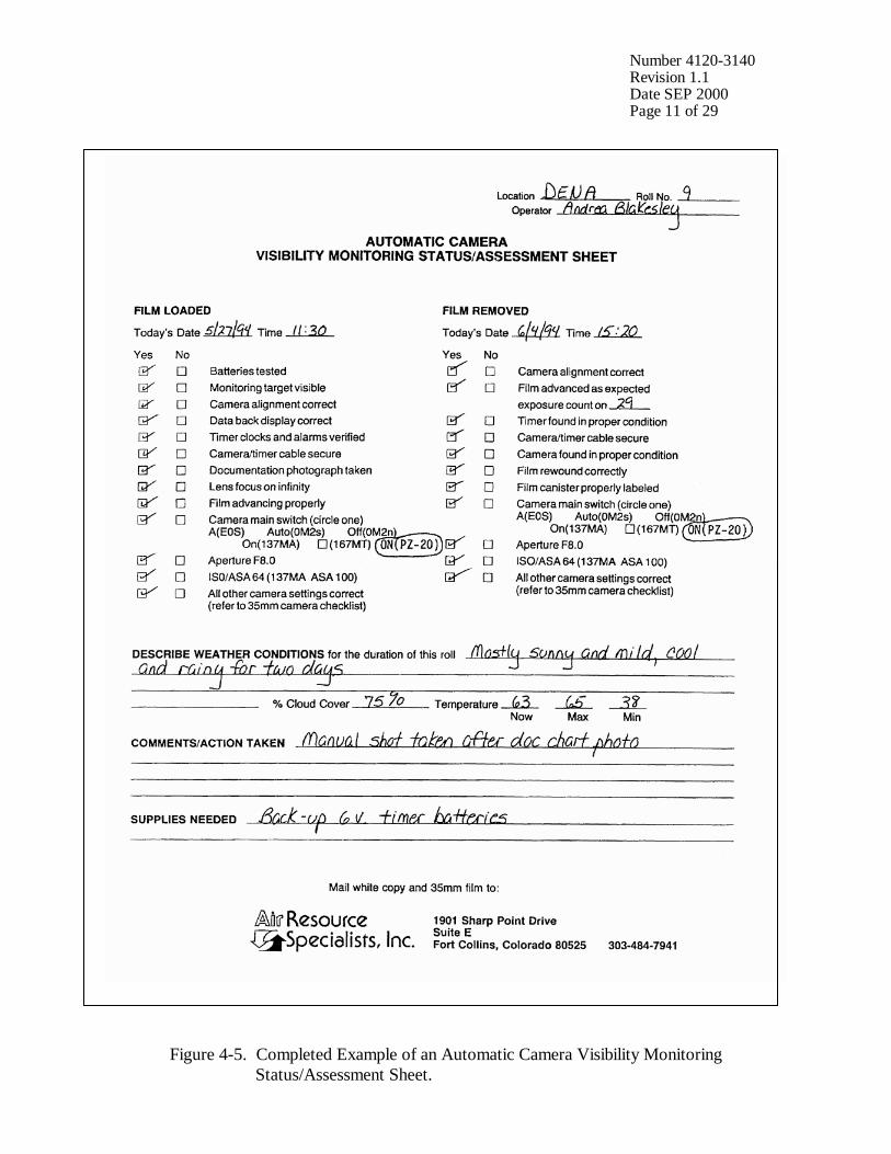
Number 4120-3140 Revision 1.1 Date SEP 2000 Page 11 of 29
Figure 4-5. Completed Example of an Automatic Camera Visibility Monitoring Status/Assessment Sheet.
Number 4120-3140 Revision 1.1 Date SEP 2000 Page 12 of 29
VISIBILITY MONITORING (continued)
• Plumes
• Severity of haze
• Emission source activity (e.g., nearby forest fires, controlled burns, construction, dusty roads, residential wood burning, etc.)
• Any perceptible odors (e.g., wood smoke)
COMMENTS Describe any equipment or monitoring discrepancies found, troubleshooting or scheduled maintenance performed, and/or corrective actions taken.
SUPPLIES NEEDED List any servicing supplies or documentation materials required for ongoing monitoring.
4.1.2 Status/Assessment Sheet Film Removal Section INSPECT ENCLOSURE Inspect the interior and exterior of the enclosure for damage or
other problems (water leakage, etc.). Inspect the outside of the enclosure window for dirt and clean if necessary.
VERIFY CAMERA ALIGNMENT
The camera alignment must remain constant from one roll to the next. Look through the camera viewfinder to verify that the alignment has remained correct during the monitoring period. If not, note the degree of misalignment and the probable cause.
VERIFY CAMERA/TIMER CABLES
Check the camera/timer and power system (6 V lantern batteries) cable connections. Verify that all cables are secure. Check the integrity of the cables and component connectors. Document any problems, including broken connectors, loose or bare wires, etc. Report any problems promptly to ARS.
REMOVE CAMERA Push the QUICK RELEASE lever on the tripod plate and lift the camera off the mount. Disconnect the camera/timer cable from the timer at the timer jack and remove the camera from the enclosure.
DOCUMENT EXPOSURE NUMBER COUNT
The frame counter indicates if the film advanced properly and how many photographs were taken during the monitoring period. Document whether the film advanced correctly and the observed exposure count number. Report any discrepancies promptly to ARS. If the film is already rewound, the film-load check mark will be flashing ( ). Assume all 36 exposures were taken and document as such.
Number 4120-3140 Revision 1.1 Date SEP 2000 Page 13 of 29
VERIFY SETTINGS Verify all camera and timer settings. Document any settings that are different from those listed on the Visibility Monitoring Status/Assessment Sheet, whether they are site-specific settings or settings made in error. (Site-specific settings may be required at sites where non-standard exposure settings are necessary to ensure quality photographs). Correct any inconsistencies.
REWIND FILM Observe the film-load check mark ( ) on the display panel: • If flashing, the film was automatically rewound after the last
frame was exposed.
• If the roll of film has not been completely exposed, pull the HOT SHOE COVER off the top of the camera. Depress the AUXILIARY REWIND button with the protruding section of the hot shoe cover. (The camera main switch must be in the “ON” position).
During rewind, the film-load check mark ( ) will flash and the exposure counter counts frame numbers in reverse. The film rewind stops automatically when the film has been completely rewound. Do not open the back until the film-load check mark flashes.
REMOVE FILM AND COMPLETE CANISTER LABEL
Remove exposed film from the camera and place it in the most recently labeled plastic canister. Complete the film canister label by writing in the current date and time. Inspect film compartment for fragments of film. Blow lightly into the compartment to remove film fragments or other particles. DO NOT TOUCH the DX film contacts or shutter curtain.
COMPLETE VISIBILITY MONITORING STATUS/ASSESSMENT SHEET
Document: • Any equipment or monitoring discrepancies found.
• All servicing or maintenance actions performed (e.g., date of
battery changes, cables tightened, timer re-programmed, etc.)
• Current and recent weather conditions.
• Current and recent visibility conditions.
4.1.3 Status/Assessment Sheet Film Loading Section LABEL FILM CANISTER
The film canister label identifies the contents of each roll of film. All of the information on the label is permanently logged at ARS When the film is received.
Number 4120-3140 Revision 1.1 Date SEP 2000 Page 14 of 29
LABEL FILM CANISTER (continued)
Open a box of new, unexposed film and remove the plastic film canister. Fill out a film canister label with the following information and attach it to the outside of the plastic canister: • Monitoring site abbreviation
• Roll number
• Date and time loaded
• Emulsion number and expiration date (information listed on
Kodak film box)
LOAD FILM To open the camera back, push the BACK COVER LATCH down. The Pentax PZ-20 loads the film automatically if the following steps are carefully taken: • Remove the film cartridge from the plastic film canister, open
the camera back, and insert the film cartridge into the film chamber, upper flat end first.
• Pull the film leader across the shutter curtain until its tip is aligned with the orange index bar marked “FILM.”
• Make sure the film has no slack and that its perforations are properly engaged with the sprocket teeth.
• Firmly close the camera back cover. The film will automatically advance and stop when “1” appears in the display panel.
NOTE: If the film is not loaded correctly, the film transport
symbol ( ) will flash after the camera motor has stopped and the shutter will not release. Open the back cover and reload the film.
Store the empty, labeled plastic film canister inside the camera enclosure until the film is removed.
INSPECT CAMERA LENS Inspect the exterior of the UV filter mounted on the camera lens for any accumulation of dust, dirt, or fingerprints. If accumulation is noted: • Clean the outside of the UV filter with the lens paper and fluid
provided.
• If necessary, unscrew the UV filter and clean the lens and inside surface of the UV filter. Do not remove the lens from the camera body or attempt to clean inner surface of the lens.
• Use lens paper and fluid to clean the viewfinder eyepiece when necessary.
Number 4120-3140 Revision 1.1 Date SEP 2000 Page 15 of 29
PHOTOGRAPH DOCUMENTATION BOARD
The first exposure on every roll must be of the documentation which contains the gray scale, color chart, battery servicing record, and pertinent data collection information (Figure 4-6). • Write the following on the note pad provided: - Monitoring site name or abbreviation - Roll number - Date and time • Adjust your position and turn the focus ring to achieve a
close-up, sharply focused photograph.
• Press the SHUTTER BUTTON. Manually turn the advance lever. Verify that the film counter has incremented one frame.
• Reset the focus ring to infinity. The documentation chart should be evenly lit for the photograph. The board is mounted to the enclosed door with Velcro tabs and may be temporarily removed if proper lighting conditions are not possible in its normal position. You may have to shift your position slightly to find a spot where there is no glare from the sun on the board.
CHECK CAMERA BATTERY
Observe the display panel. If a battery symbol ( ) appears in the display directly above the film transport symbol ( ) the level of battery power is: • ( ) - nearly exhausted, replace with new battery
• ( ) flashing - very low, shutter will not release, replace
with new battery
• blank display - drained, replace with new battery If required, change the camera’s 6 V lithium battery and retest the system. Document all battery changes on the Visibility Monitoring Status/Assessment Sheet and “battery servicing record” portion of the documentation chart. Report any problems promptly to ARS. Camera battery change procedures are described further in Section 4.2.2.
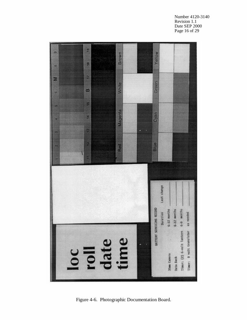
Number 4120-3140 Revision 1.1 Date SEP 2000 Page 16 of 29
Figure 4-6. Photographic Documentation Board.
Number 4120-3140 Revision 1.1 Date SEP 2000 Page 17 of 29
CHECK CAMERA SETTINGS
Verify and change, if necessary, all camera settings for correct automatic operation. Standard settings for the Pentax PZ-20 are: Main Switch ON Aperture f8.0 ISO/ASA 64 Exposure Compensation 0.0 Program Mode Selection A Drive Mode Selector ! (single) Lens Focus Mode MF (manual) Lighting conditions of the target or vista may require site-specific exposure settings. Setting changes directed by ARS are documented on the enclosure door and in the Automatic 35 mm Camera System User’s Manual provided in the site operator’s manual. Document any settings that are different from those listed above on each Visibility Monitoring Status/Assessment Sheet.
CHECK DATABACK SETTING AND BATTERIES
The databack should be in the “day-time” mode displaying the current day of the month and current time, with the bar mark ( - ) displayed directly above the minutes. If the display is blank, the databack battery is drained. Replace the batteries only when the film is not loaded. Document all battery changes on the Visibility Monitoring Status/Assessment Sheet and “battery servicing record” portion of the documentation chart. Reset the databack for the current date and time. Databack setting and programming instructions, as well as battery change procedures are described further in Section 4.2.
CHECK TIMER SETTINGS
Review timer display: • The Paragon EC72D should be in the “RUN” mode
displaying the local time and day-of-week, and the colon should be flashing.
• If the display is incorrect press RUN on the display panel to verify that the timer is in the “RUN” mode. If the time, date, or display is still incorrect, reset the timer.
• If the timer display is blank, the timer battery wiring may be incorrect or the battery power may be insufficient.
Review the programmed timer events: • Press PRG then C1 to select Channel 1 for review.

Number 4120-3140 Revision 1.1 Date SEP 2000 Page 18 of 29
CHECK TIMER SETTINGS (continued)
• Press E repeatedly to review each event. In normal operation, Event 1 (E:01) is 0900, Event 2 (E:02) is 1200, and Event 3 (E:03) is 1500. The remaining events are not programmed.
If events are incorrect, reprogram the timer clock and timer events. Timer setting and programming instructions are provided in Section 4.2.3. Press RUN when finished reviewing or changing events to return the timer to the “RUN” mode. NOTE: If a photograph was scheduled to occur while you
were reviewing or programming information, the photograph was not taken.
REPLACE AND ALIGN CAMERA
It is important for the alignment to be consistent from one roll to the next. • Mount the camera on the tripod head.
• Securely reconnect the camera/timer cable to the timer at the
timer jack.
• Look through the viewfinder and align the camera on the vista to be photographed.
• Verify that the alignment matches the previous alignment, the horizon is level, the enclosure port does not appear in the frame, and the lens focus is on infinity. (A 3” x 5” site alignment photograph is provided in the camera enclosure for reference).
• Firmly tighten all levers on the tripod head and recheck the alignment.
If weather conditions obscure the target area, use foreground features to judge alignment. Visit the site again when the weather clears to recheck the alignment.
VERIFY CAMERA/TIMER CABLES AND FILM ADVANCE
Verify the camera/timer and power system (6 V lantern batteries) cable connections. Test the timer and battery cable connections: • The timer must be in the “RUN” mode, with the time and
day-of-week displayed and colon flashing.
• Press C1; the camera should fire. The timer automatically returns to the “RUN” mode.
If the camera does not fire, the camera/timer wiring is incorrect or the battery power to the timer is insufficient.

Number 4120-3140 Revision 1.1 Date SEP 2000 Page 19 of 29
VERIFY CAMERA/TIMER CABLES AND FILM ADVANCE (continued)
Test the camera/timer cable connection: • Gently shake the camera/timer cable leading into the camera
remote jack. If the camera fires, an electrical short may exist in a portion of the cable jack(s).
Document any discrepancies and/or corrective actions taken. Report any problems promptly to ARS.
DOCUMENT FINDINGS AND ACTIONS PERFORMED
Document any servicing or maintenance actions performed during the film loading process. Place the completed Visibility Monitoring Status/Assessment Sheet (yellow copy) in the Site Operator’s Manual for Automatic Visibility Monitoring Camera Systems.
CLOSE AND SECURE ENCLOSURE
Place the Site Operator’s Manual for Automatic Visibility Monitoring Camera Systems inside the camera enclosure for future reference. Close and lock the camera enclosure door. Tighten all door seal clamps and padlock the enclosure door hasp.
4.1.4 Mailing the Film and Completed Status/Assessment Sheet Place the original (white) copy of the Visibility Monitoring Status/Assessment Sheet and corresponding roll of film in a padded mailing envelope. Mail both the film and the Visibility Monitoring Status/Assessment Sheet immediately to: Air Resource Specialists, Inc. 1901 Sharp Point Drive, Suite E Fort Collins, CO 80525 Attention: Photographic Data Coordinator Call ARS immediately if any inconsistencies were noted or if any questions arise. Many problems can be resolved through telephone consultation. ARS may be reached at the following telephone numbers: Telephone: 970/484-7941 Fax: 970/484-3423 Detailed troubleshooting procedures to assist with telephone-directed problem resolution are presented in TI 4120-3340, Troubleshooting and Emergency Maintenance Procedures for 35 mm Automatic Camera System - Pentax PZ-20. 4.2 SCHEDULED MAINTENANCE Proper film storage and periodic preventive maintenance will help to ensure consistent, high quality data collection. Preventive maintenance servicing visits are performed as scheduled or required by the data coordinator.

Number 4120-3140 Revision 1.1 Date SEP 2000 Page 20 of 29
Scheduled maintenance normally consists of:
• Camera battery changes (every six months)
• Databack battery changes (annually)
• Timer battery changes (every six months) Replacement camera and timer batteries are provided by ARS with each film shipment (every six months). Replacement databack batteries are provided annually. Additional batteries will be provided as needed or as requested by the site operator. Test all batteries with a voltmeter before placing them in the system component. Verify all timer or camera battery malfunctions by testing removed component batteries with a voltmeter. Additional servicing tasks identified by the data coordinator may include:
• Camera, databack, and timer configuration checks or changes
• Camera alignment changes
• Revision of data collection procedures All scheduled maintenance requested by the data coordinator or performed by the site operator must be thoroughly documented on the Visibility Monitoring Status/Assessment Sheet and in the site-specific Quality Assurance Database. Any equipment malfunctions or data collection discrepancies observed during a scheduled maintenance visit should be reported to ARS immediately. The following subsections further describe proper methods for film storage, scheduled maintenance procedures, and corresponding servicing documentation. Troubleshooting and emergency maintenance procedures for the Pentax PZ-20 are provided in TI 4120-3340, Troubleshooting and Emergency Maintenance Procedures for 35 mm Automatic Camera System - Pentax PZ-20. 4.2.1 Film and Film Storage Only Kodachrome 64 slide film provided by ARS should be loaded into the visibility monitoring camera unless otherwise directed. Each roll of film has an emulsion number and expiration date. This information must be documented on the canister label of each exposed film roll (see Section 4.1.3). Photographic film is sensitive to heat and moisture. These elements can affect the film, altering both the processed photographs and the data analysis. For example, film subjected to heat often has a pink or purple cast while film subjected to moisture does not process consistently. To ensure proper film storage, keep the film inside a Ziploc bag with desiccant and place the bag inside the clearly labeled film storage box. The box should be stored in a freezer, refrigerator, or cool (less than 70°F), dry location. If stored in a freezer, allow film to thaw at room temperature for at least two hours before loading it in the camera.
Number 4120-3140 Revision 1.1 Date SEP 2000 Page 21 of 29
4.2.2 Changing System Batteries CAMERA BATTERY CHANGE
The Pentax PZ-20 camera runs on one 6 V lithium battery pack. This battery should be replaced every six months or as directed by the data coordinator. • Open the battery chamber cover by pulling the cover lock in
the direction of the arrow.
• Turn the camera upright and allow the battery to slide out of the compartment. Measure and record the voltage of the used battery.
• Remove the new battery from its packaging and test and record the voltage. The new battery should measure at least 6 volts.
• Insert the new battery end first and lock it in place by closing the battery chamber cover.
• After changing the battery, check it as described in Section 4.1.3.
DATABACK BATTERY CHANGE
The Pentax Data Back FE runs on one 3 V coin-shaped lithium battery. The databack battery should be replaced annually, or as required by the data coordinator. Be sure to replace the battery only when film is not loaded. • The battery compartment is located on the bottom of the
camera back cover. To open the compartment, use a fingernail or small screwdriver and press down.
• The battery holder will pop out and can then be removed. Measure and record the voltage of the used battery.
• Remove the new battery from its packaging and test and record the voltage. The new battery should measure approximately 3 volts.
• Wait 15 seconds after removing the used battery and then load the new battery with the “+” side facing up.
• Slide the battery holder into the battery compartment until it locks in place.
• Check the display and reset the databack for the current date and time as described in Section 4.1.3.
Number 4120-3140 Revision 1.1 Date SEP 2000 Page 22 of 29
TIMER BATTERY VERIFICATION AND CHANGES
The Paragon EC72D timer runs on two 6 V lantern batteries. Both 6 V lantern batteries should be replaced biannually or as directed by the data coordinator. To test the main power source (two 6 volt batteries): • The timer must be in “RUN” mode, with the time and day
displayed and colon flashing.
• Press C1; the camera should fire. The timer automatically returns to the “RUN” mode.
• If the camera does not fire, the camera/timer wiring is incorrect or the battery power to the timer is insufficient. Test and record the voltage of the used batteries. Camera/timer wiring verification procedures are described in Section 4.1.3.
To change the 6 volt batteries (Figure 4-7): • Remove battery cover (located above timer control panel) by
pressing sides together and pulling left or right.
• Snap a 9 V battery into the battery clip.
• Temporarily attach a 9 V battery to the back of the timer (see Figure 4-1). The 9 V will help the timer hold its programmed memory while you change the main power batteries.
• Disconnect all wires from the used batteries.
• Place the new 6 V batteries together at opposite polarity (in series).
• Connect the two 6 V batteries at one end.
• Connect the opposite terminals to the cable from the timer.
• Disconnect the 9 V battery and replace the battery cover.
• Perform the above test to assure the connections are secure.
• Measure the voltage of the new batteries as shown in Figure
4-7. The measurement should be approximately 12 volts.
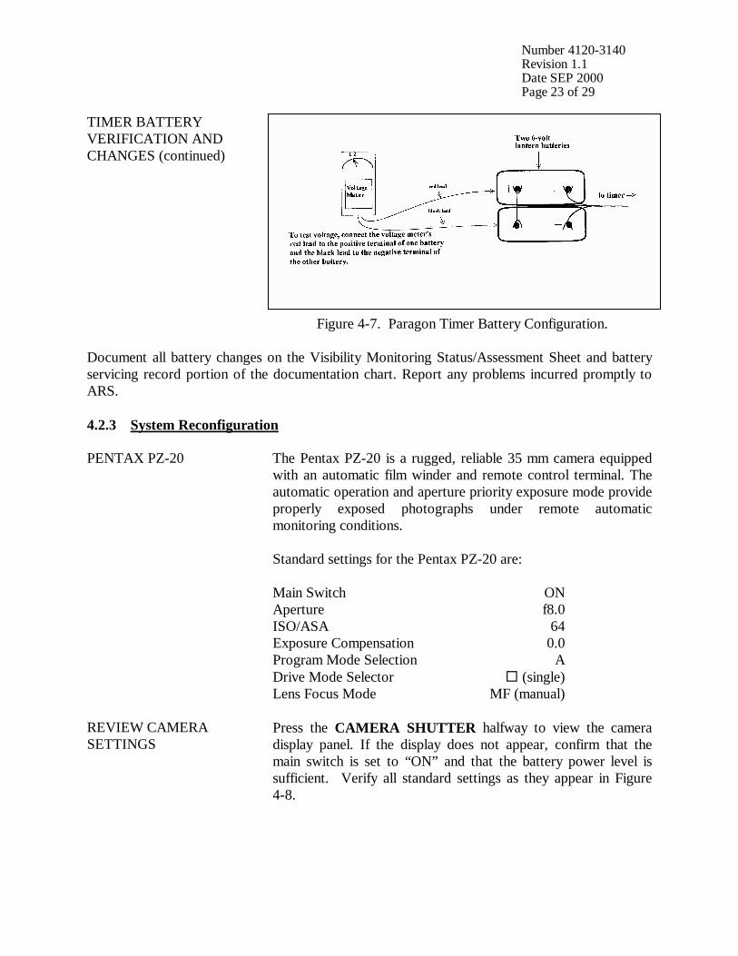
Number 4120-3140 Revision 1.1 Date SEP 2000 Page 23 of 29
TIMER BATTERY VERIFICATION AND CHANGES (continued)
Figure 4-7. Paragon Timer Battery Configuration. Document all battery changes on the Visibility Monitoring Status/Assessment Sheet and battery servicing record portion of the documentation chart. Report any problems incurred promptly to ARS. 4.2.3 System Reconfiguration PENTAX PZ-20 The Pentax PZ-20 is a rugged, reliable 35 mm camera equipped
with an automatic film winder and remote control terminal. The automatic operation and aperture priority exposure mode provide properly exposed photographs under remote automatic monitoring conditions. Standard settings for the Pentax PZ-20 are: Main Switch ON Aperture f8.0 ISO/ASA 64 Exposure Compensation 0.0 Program Mode Selection A Drive Mode Selector ! (single) Lens Focus Mode MF (manual)
REVIEW CAMERA SETTINGS
Press the CAMERA SHUTTER halfway to view the camera display panel. If the display does not appear, confirm that the main switch is set to “ON” and that the battery power level is sufficient. Verify all standard settings as they appear in Figure 4-8.

Number 4120-3140 Revision 1.1 Date SEP 2000 Page 24 of 29
REVIEW CAMERA SETTINGS (continued)
Figure 4-8. Pentax PZ-20 Display Panel.
CHANGE CAMERA SETTINGS
Lighting conditions of the target or vista may require site-specific exposure settings. Setting changes directed by ARS should be noted on the Visibility Monitoring Status/Assessment Sheet for each roll of film that the setting is in effect. Refer to the Pentax PZ-20 manufacturers’ instruction booklet for detailed camera setting procedures.
PENTAX DATA BACK FE The date and time that a visibility monitoring photograph was taken is vital information for analysis. The Pentax Data Back FE automatically imprints selected data on the film.
REVIEW DATABACK SETTINGS
During regular operation, the Pentax Data Back FE should display the local date and time. Verify that the bar mark (-) appears above the minutes to ensure the databack is in the “IMPRINT” mode (Figure 4-9).
Figure 4-9. Pentax Data Back FE Displays.
Number 4120-3140 Revision 1.1 Date SEP 2000 Page 25 of 29
REVIEW DATABACK SETTINGS (continued)
NOTE: Standard/Daylight-Saving Time Changes: Every spring and fall it will be necessary to change the databack clock to correspond with local standard or local daylight time. The data coordinator will provide a reminder postcard to document changes made.
To set the Pentax Data Back FE: • Press the MODE button until the “DAY/HOUR/MINUTE”
mode is displayed.
• Press the SELECT button once -- the “HOUR” display will flash.
• Press the ADJUST button until the correct hour is displayed. Constant pressure on the “ADJUST” button will rapidly advance the numbers.
• Press the SELECT button -- the “MINUTES” display will
flash. Press the ADJUST button until the correct minutes are displayed.
• Press the MODE button four times until the “YEAR/MONTH/DAY” mode is displayed.
• Press the SELECT button -- the “YEAR” display will flash. Press the ADJUST button until the correct year is displayed.
• Press the SELECT button -- the “MONTH” display will flash. Press the ADJUST button until the correct month is displayed.
• Press the SELECT button -- the “DAY” display will flash.
Press the ADJUST button until the correct day is displayed.
• Press the MODE button once to return to the “DAY AND TIME” mode. A bar mark ( - ) should appear in the upper right corner of the display. This indicates the databack is in the “IMPRINTING” mode. The databack should remain in this mode during regular operation.
PARAGON EC72D TIMER
The Paragon automatic timer is normally programmed for three photographs a day at 0900, 1200, and 1500. If necessary, alternate sampling schedules can be programmed for 1 to 32 user-selected photographs a day. Routine servicing schedules are based on the number of photographs taken. • 3 photographs/day = 10-11 day servicing schedule.
• 2 photographs/day = 15-17 day servicing schedule.
Number 4120-3140 Revision 1.1 Date SEP 2000 Page 26 of 29
PARAGON EC72D TIMER (continued)
• 1 photograph/day = 30-33 day servicing schedule. During regular operation the Paragon EC72D should be in the “RUN” mode displaying the local time and day-of-week (Sunday = 1; Saturday = 7) with the colon flashing.
SETTING THE PARAGON EC72D TIMER
To set the timer clock: • Wire power (two 6 V lantern batteries) to timer. A “0:00 1” is
displayed, with a colon and “1” flashing. Press CLK; the flashing stops.
• Using the 24-hour clock format, press four keys for the current time (e.g., 1015 = 10:15 a.m.). Press one key for the current date of the week; (1 = Sunday . . . 7 = Saturday). Press E to enter.
• “101” is displayed, indicating “January 1”. Press two keys for the current month and two keys for the current date (e.g., 0615 = June 15). Press E to enter.
• “84” is displayed, indicating “1984”. Press two keys for the current year (e.g., 90). Press E to enter. Control will automatically switch to the “RUN” mode. The time and day of week will be displayed with the colon flashing.
To program times for photographs to be taken: • Press PRG to enter “program” mode.
• Press C1 to select Channel 1 for programming; “E:01” (for
the first event) is displayed.
• Press four keys for the time the first photograph should be taken (e.g., 0900 for 9:00 a.m.). Press 0 to program the event to occur daily. Press E to enter the event into memory.
• The next event slot will be displayed (e.g., E:02). Repeat the step immediately above for each time of the day a photograph should be taken.
• Press RUN to return to “RUN” mode after all selected photograph times are programmed.
Procedures to review programmed timer events are provided in Section 4.1.3.
Number 4120-3140 Revision 1.1 Date SEP 2000 Page 27 of 29
SETTING THE PARAGON EC72D TIMER (continued)
NOTE: If more than 16 photographs per day are desired, Channel 2 may be used to program up to 16 additional events provided the Channel 2 output terminals have also been wired to the camera.
SITE-SPECIFIC CAMERA ALIGNMENT
Correct alignment of the camera is extremely important. Each photograph is compared to others of the same view during analysis. Therefore, alignment must remain constant from one roll of film to the next. A 3” x 5” site alignment photograph is provided for your reference in the camera enclosure. Alignment changes or adjustments may be necessary when: • Selected features are not properly framed in the view, and/or
• Exposure discrepancies result from intruding foreground or
backlit features. Any alignment change directed by ARS should be fully documented on the Visibility Monitoring Status/Assessment Sheet.
VERIFY CAMERA ALIGNMENT
Look through the viewfinder to verify the following: • The alignment matches the referenced site-specific alignment
photograph.
• The horizon is level.
• The vista is framed correctly.
• The sunshield and port are not visible in the viewfinder.
• The lens focus is on infinity. Document any misalignment found and assess probable cause on the Visibility Monitoring Status/Assessment Sheet. If weather conditions obscure the target area, use foreground features to judge alignment. Visit the site again when the weather clears to recheck the alignment. Procedures to ensure ongoing alignment are provided in TI 4120-3340, Troubleshooting and Emergency Maintenance Procedures for 35 mm Automatic Camera System - Pentax PZ-20.
Number 4120-3140 Revision 1.1 Date SEP 2000 Page 28 of 29
4.2.4 On-Site Data Control During each routine site visit, the operator documents maintenance performed and notes all discrepancies on the Visibility Monitoring Status/Assessment Sheet. The completed original (white copy) is mailed with each roll of film. A copy (yellow) is kept in the Site Operator’s Manual for Automatic Visibility Monitoring Camera Systems. If discrepancies or operator comments on the sheets indicate that further action is necessary, immediate corrective action is taken. Throughout the monitoring effort, ARS and site operators maintain close personal communications. Operators are encouraged to call or notify ARS if they have questions or problems. Ongoing review of film and site operator documentation often initiates corrective actions. Common data collection problems identified include:
• Roll number discrepancies
• Missing or improperly exposed documentation chart photographs
• Improper film loading or rewinding
• Late film changes
• Improper camera alignment
• Incorrect camera settings
• Weak or missing databack imprinting
• Incorrect timer settings
• Incomplete Visibility Monitoring Status/Assessment Sheet documentation All scheduled maintenance requested by the data coordinator or performed by the site operator must be thoroughly documented on the Visibility Monitoring Status/Assessment Sheet and in the site-specific Quality Assurance Database. If necessary, a Photographic Monitoring Network Quality Assessment Log (Figure 4-10) is mailed to the site to further document corrective actions taken. The site operator documents the date of correction and what was done, and returns a carbon copy of the log to ARS. Problems and equipment malfunctions requiring extensive troubleshooting and/or maintenance are fully described in TI 4120-3340.

Number 4120-3140 Revision 1.1 Date SEP 2000 Page 29 of 29
PHOTOGRAPHIC MONITORING NETWORK QUALITY ASSESSMENT LOG
Site: __________________________ Date: ________________________________ _________________________ Operator: ______________________ From: _________________________ PROBLEM DESCRIPTION: ___________________________________________________________________________ ___________________________________________________________________________ ___________________________________________________________________________ ___________________________________________________________________________ ACTION REQUEST: ___________________________________________________________________________ ___________________________________________________________________________ ___________________________________________________________________________ ___________________________________________________________________________ ___________________________________________________________________________ ___________________________________________________________________________ ___________________________________________________________________________ ___________________________________________________________________________ CORRECTIVE ACTION TAKEN (to be completed by site operator): ___________________________________________________________________________ ___________________________________________________________________________ ___________________________________________________________________________ ___________________________________________________________________________ ___________________________________________________________________________ ___________________________________________________________________________ Date: ________________________ Operator: ________________________________
Return Yellow Copy To: White - Original, site copy Yellow - return to ARS Pink - ARS retain
Figure 4-10. Photographic Monitoring Network Quality Assessment Log.
QUALITY ASSURANCE/QUALITY CONTROL DOCUMENTATION SERIES TITLE
ROUTINE SITE OPERATOR MAINTENANCE PROCEDURES FOR 35 MM AUTOMATIC CAMERA SYSTEM – PENTAX ZX-10
TYPE
TECHNICAL INSTRUCTION
NUMBER
4120-3150
DATE
JANUARY 1999
AUTHORIZATIONS
TITLE NAME SIGNATURE
ORIGINATOR Karen K. Rosener
PROJECT MANAGER James H. Wagner
PROGRAM MANAGER David L. Dietrich
QA MANAGER Gloria S. Mercer
OTHER
REVISION HISTORY
REVISION NO.
CHANGE DESCRIPTION DATE AUTHORIZATIONS
Reviewed; no changes necessary. January 2000
0.1 Delete references to 9v battery in timer. September 2000
Reviewed; no changes necessary. September 2001
Reviewed; no changes necessary. September 2002
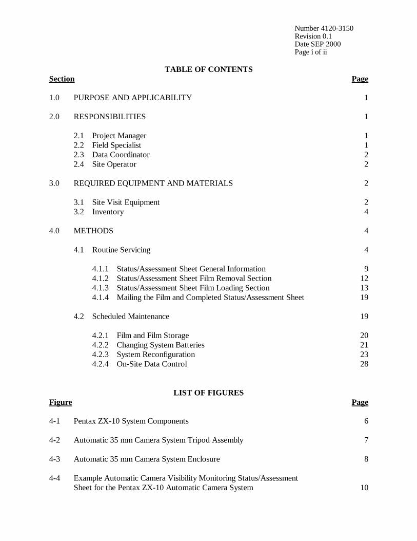
Number 4120-3150 Revision 0.1 Date SEP 2000 Page i of ii
TABLE OF CONTENTS Section Page 1.0 PURPOSE AND APPLICABILITY 1 2.0 RESPONSIBILITIES 1 2.1 Project Manager 1 2.2 Field Specialist 1 2.3 Data Coordinator 2 2.4 Site Operator 2 3.0 REQUIRED EQUIPMENT AND MATERIALS 2 3.1 Site Visit Equipment 2 3.2 Inventory 4 4.0 METHODS 4 4.1 Routine Servicing 4 4.1.1 Status/Assessment Sheet General Information 9 4.1.2 Status/Assessment Sheet Film Removal Section 12 4.1.3 Status/Assessment Sheet Film Loading Section 13 4.1.4 Mailing the Film and Completed Status/Assessment Sheet 19 4.2 Scheduled Maintenance 19 4.2.1 Film and Film Storage 20 4.2.2 Changing System Batteries 21 4.2.3 System Reconfiguration 23 4.2.4 On-Site Data Control 28
LIST OF FIGURES Figure Page 4-1 Pentax ZX-10 System Components 6 4-2 Automatic 35 mm Camera System Tripod Assembly 7 4-3 Automatic 35 mm Camera System Enclosure 8 4-4 Example Automatic Camera Visibility Monitoring Status/Assessment Sheet for the Pentax ZX-10 Automatic Camera System 10
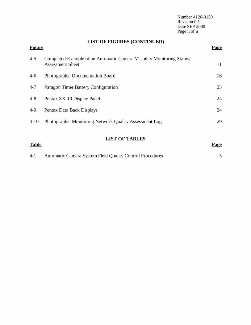
Number 4120-3150 Revision 0.1 Date SEP 2000 Page ii of ii
LIST OF FIGURES (CONTINUED) Figure Page 4-5 Completed Example of an Automatic Camera Visibility Monitoring Status/ Assessment Sheet 11 4-6 Photographic Documentation Board 16 4-7 Paragon Timer Battery Configuration 23 4-8 Pentax ZX-10 Display Panel 24 4-9 Pentax Data Back Displays 24 4-10 Photographic Monitoring Network Quality Assessment Log 29
LIST OF TABLES Table Page 4-1 Automatic Camera System Field Quality Control Procedures 5
Number 4120-3150 Revision 0.1 Date SEP 2000 Page 1 of 29
1.0 PURPOSE AND APPLICABILITY The purpose of routine site operator maintenance is to assure quality data capture and minimize data loss by performing and documenting scheduled operational checks and preventive maintenance. This technical instruction (TI) describes the steps of a routine site visit, scheduled maintenance, and on-site data control for the Pentax ZX-10 35 mm camera system. Routine servicing schedules are based on the number of photographs taken each day. Assuming a three-photograph per day schedule, site operators service the camera approximately every 10 days to change film, check the performance of the camera system, clean system components, and perform troubleshooting and/or emergency maintenance as required. Preventive maintenance site visits are performed every six months or as required by the data coordinator. The effective performance and documentation of each of these tasks is the key to quality data collection and minimal data loss. Site operators should be fully trained and supplied with a Site Operator’s Manual for Automatic Visibility Monitoring Camera Systems that contains detailed routine site operator maintenance and troubleshooting procedures for the specific camera monitoring system(s) located at the site. Additional manufacturer instruction booklets and a supply of Visibility Monitoring Status/Assessment Sheets are also provided. Close personal communications should be maintained between Air Resource Specialists, Inc. (ARS) and site operators throughout the monitoring effort. Operators are encouraged to call or notify ARS if they have any questions or problems. Many problems can be fully resolved over the telephone. 2.0 RESPONSIBILITIES 2.1 PROJECT MANAGER The project manager shall coordinate with the site operator, his/her supervisor, field specialist, and data coordinator concerning the schedule and requirements for routine maintenance. 2.2 FIELD SPECIALIST The field specialist shall:
• Coordinate with the project manager, the site operator, his/her supervisor, and data coordinator concerning the schedule and requirements for routine maintenance.
• Train the site operator in all phases of camera system maintenance. • Provide technical support to the site operator via telephone to assure high quality site
visits. • Resolve problems reported by the site operator. • Document all technical support provided to the site operator.

Number 4120-3150 Revision 0.1 Date SEP 2000 Page 2 of 29
2.3 DATA COORDINATOR The data coordinator shall:
• Coordinate with the project manager, the site operator, his/her supervisor, and field specialist concerning the schedule and requirements for routine maintenance.
• Verify that scheduled visits are performed and notify the site operator if he/she fails to
make a scheduled visit.
• Review all site documentation completed by the site operator for accuracy and completeness. File all documentation and correspondence.
• Resolve problems reported by the site operator.
• Enter the results of all performed procedures into the site-specific Quality Assurance
Database.
• Supply the site operator with all necessary monitoring supplies.
• Coordinate the replacement and repair of all malfunctioning units.
• Document all capital instrumentation changes and maintain inventory records in the ARS Purchase Order/Inventory Database.
2.4 SITE OPERATOR The site operator shall:
• Coordinate with his/her supervisor, the project manager, data coordinator, and field specialist concerning the schedule and requirements for routine maintenance.
• Schedule regular site maintenance visits and perform all procedures described in this
TI.
• Thoroughly document all procedures on the Visibility Monitoring Status/Assessment Sheet; mail the white copy of the completed sheet to the data coordinator and maintain an on-site file of the yellow copy.
• Immediately report any noted inconsistencies to the data coordinator or field specialist.
3.0 REQUIRED EQUIPMENT AND MATERIALS 3.1 SITE VISIT EQUIPMENT Equipment and materials generally required to support a routine site visit or scheduled maintenance include:
• Medium and small flat-blade screwdriver
• Small Phillips-head screwdriver
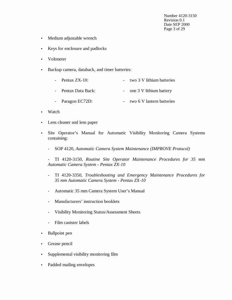
Number 4120-3150 Revision 0.1 Date SEP 2000 Page 3 of 29
• Medium adjustable wrench
• Keys for enclosure and padlocks
• Voltmeter
• Backup camera, databack, and timer batteries: - Pentax ZX-10: - two 3 V lithium batteries - Pentax Data Back: - one 3 V lithium battery - Paragon EC72D: - two 6 V lantern batteries
• Watch
• Lens cleaner and lens paper
• Site Operator’s Manual for Automatic Visibility Monitoring Camera Systems containing:
- SOP 4120, Automatic Camera System Maintenance (IMPROVE Protocol) - TI 4120-3150, Routine Site Operator Maintenance Procedures for 35 mm
Automatic Camera System - Pentax ZX-10 - TI 4120-3350, Troubleshooting and Emergency Maintenance Procedures for
35 mm Automatic Camera System - Pentax ZX-10 - Automatic 35 mm Camera System User’s Manual - Manufacturers’ instruction booklets - Visibility Monitoring Status/Assessment Sheets - Film canister labels
• Ballpoint pen
• Grease pencil
• Supplemental visibility monitoring film
• Padded mailing envelopes
Number 4120-3150 Revision 0.1 Date SEP 2000 Page 4 of 29
3.2 INVENTORY It is imperative that any capital instrumentation changes made as a result of routine maintenance be thoroughly documented. Specific model and serial numbers of the exchanged enclosure, camera body, lens, databack, and/or automatic timer should be documented for future reference by the data coordinator in the site-specific Quality Assurance Database and ARS Purchase Order/Inventory Database. Any on-site changes made should be documented by the site operator on a Visibility Monitoring Status/Assessment Sheet. Capital equipment exchange procedures are discussed in TI 4120-3350, Troubleshooting and Emergency Maintenance Procedures for 35 mm Automatic Camera System - Pentax ZX-10. 4.0 METHODS This section includes two (2) major subsections: 4.1 Routine Servicing 4.2 Scheduled Maintenance Detailed procedures described in these subsections are summarized in Table 4-1. A variety of automatic camera monitoring configurations exist. Specific equipment servicing requirements for each site will vary with the system configuration. All procedures described in this TI refer to the Pentax ZX-10 35 mm camera and Paragon EC72D automatic timer. Routine servicing procedures are summarized in the Automatic 35 mm Camera System User’s Manual for the Pentax ZX-10 System, provided in the site operator’s manual. Detailed schematic diagrams of the Pentax ZX-10 35 mm camera system and associated components are provided in Figures 4-1 through 4-3. The following manufacturers’ instruction booklets are provided for reference in the Site Operator’s Manual for Automatic Visibility Monitoring Camera Systems:
• Pentax ZX-10
• Paragon EC72, EC72D, and EC72E Resolution of problems noted during routine servicing or scheduled maintenance can be more fully investigated by following the troubleshooting and emergency maintenance procedures defined in TI 4120-3350. 4.1 ROUTINE SERVICING Routine servicing schedules are based on the number of photographs taken each day. A common monitoring schedule includes taking three photographs a day at 0900, 1200, and 1500. Assuming this schedule, site operators service the camera approximately every 10 days. Alternate monitoring schedules are discussed in Section 4.2.3. Supplemental film and backup batteries should be on hand whenever the site is visited, this will minimize servicing time and data loss should a problem occur or be detected during servicing.

Number 4120-3150 Revision 0.1 Date SEP 2000 Page 5 of 29
Table 4-1
Automatic Camera System Field Quality Control Procedures
Regular Maintenance performed at each film change: • Inspect overall system and clean shelter window. • Remove camera. • Verify that film advanced and settings are correct. • Rewind and remove film (complete film canister label). • Load new film (complete film canister label). • Inspect and clean camera lens. • Check system batteries. • Check camera and databack settings. • Check timer settings. • Photograph film documentation board. • Replace and align camera. • Verify system operation. • Complete Visibility Monitoring Status/Assessment Sheets: - Document any equipment or monitoring discrepancies found. - Document all servicing or maintenance actions performed. - Describe weather conditions. - Describe visibility conditions. • Close and lock camera enclosure. • Mail film and the white copy of the completed Visibility Monitoring Status/Assessment Sheet
to ARS. Scheduled Maintenance performed as scheduled or as required: • Change 35 mm databack batteries annually. • Change 35 mm camera batteries every 6 months. • Change 35 mm timer batteries every 6 months.
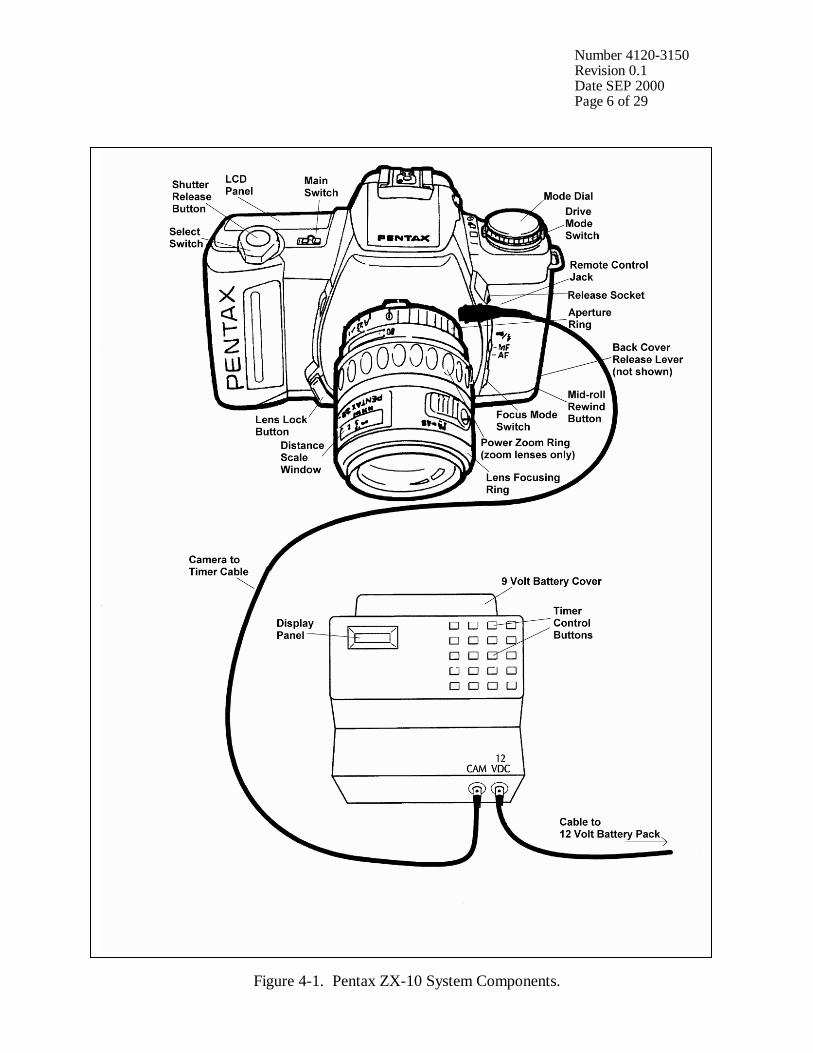
Number 4120-3150 Revision 0.1 Date SEP 2000 Page 6 of 29
Figure 4-1. Pentax ZX-10 System Components.

Number 4120-3150 Revision 0.1 Date SEP 2000 Page 7 of 29
Figure 4-2. Automatic 35 mm Camera System Tripod Assembly.
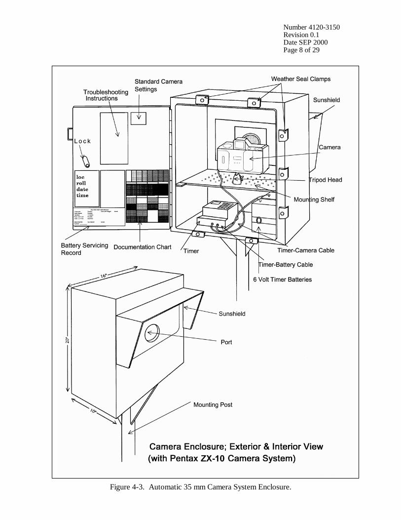
Number 4120-3150 Revision 0.1 Date SEP 2000 Page 8 of 29
Figure 4-3. Automatic 35 mm Camera System Enclosure.
Number 4120-3150 Revision 0.1 Date SEP 2000 Page 9 of 29
During each routine site visit, the operator will thoroughly document all pertinent data collection information, any maintenance performed, and note any equipment or monitoring discrepancies found on the Visibility Monitoring Status/Assessment Sheet (Figure 4-4). The site operator must complete all applicable portions of this sheet and mail the white original to the data coordinator with each roll of film. A completed example status/assessment sheet is provided in Figure 4-5. Blank status/assessment sheets are provided in the site operator’s manual. The following subsections detail how to complete the status/assessment sheet. 4.1.1 Status/Assessment Sheet General Information The following general information appears on the Visibility Monitoring Status/Assessment Sheet. LOCATION Either the full site location name or the four-letter site
abbreviation.
ROLL NO. The consecutive site roll number of the film used to document the monitoring period.
OPERATOR(S) The full name of the site operator(s).
DATE AND TIME The standard calendar date and local time when the film was loaded and when the film was removed.
WEATHER CONDITIONS At the time of film removal, describe recent and current weather conditions that may be helpful in interpreting the photographic data. Such conditions may include, but are not limited to: • Temperature extremes
• Percent cloud cover currently observed
• Severe weather (lightning, hail, high winds, etc.)
• Passing storm fronts
• Precipitation
• Stagnant air masses
• Fog
VISIBILITIY CONDITIONS
Describe recent and current visibility conditions that may be useful in verifying qualitative photographic observations. Such conditions may include, but are not limited to: • Extremely clean • Regional haze • Layered haze
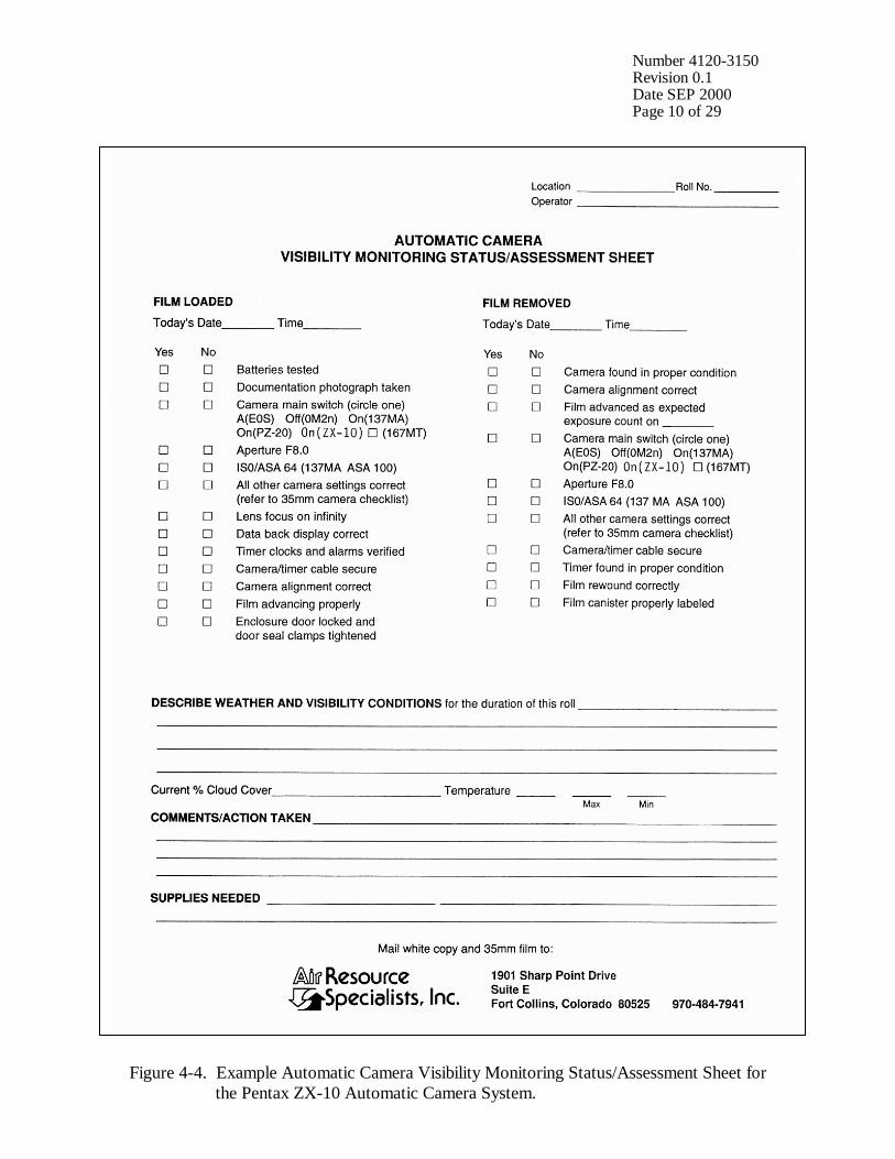
Number 4120-3150 Revision 0.1 Date SEP 2000 Page 10 of 29
Figure 4-4. Example Automatic Camera Visibility Monitoring Status/Assessment Sheet for the Pentax ZX-10 Automatic Camera System.

Number 4120-3150 Revision 0.1 Date SEP 2000 Page 11 of 29
Figure 4-5. Completed Example of an Automatic Camera Visibility Monitoring Status/Assessment Sheet.
Number 4120-3150 Revision 0.1 Date SEP 2000 Page 12 of 29
VISIBILITY CONDITIONS (continued)
• Plumes
• Severity of haze
• Emission source activity (e.g., nearby forest fires, controlled burns, construction, dusty roads, residential wood burning, etc.)
• Any perceptible odors (e.g., wood smoke)
COMMENTS Describe any equipment or monitoring discrepancies found, troubleshooting or scheduled maintenance performed, and/or corrective actions taken.
SUPPLIES NEEDED List any servicing supplies or documentation materials required for ongoing monitoring.
4.1.2 Status/Assessment Sheet Film Removal Section INSPECT ENCLOSURE Inspect the interior and exterior of the enclosure for damage or
other problems (water leakage, etc.). Inspect the outside of the enclosure window for dirt and clean if necessary.
VERIFY CAMERA ALLIGNMENT
The camera alignment must remain constant from one roll to the next. Look through the camera viewfinder to verify that the alignment has remained correct during the monitoring period. If not, note the degree of misalignment and the probable cause.
VERIFY CAMERA/TIMER CABLES
Check the camera/timer and power system (6 V lantern batteries) cable connections. Verify that all cables are secure. Check the integrity of the cables and component connectors. Document any problems, including broken connectors, loose or bare wires, etc. Report any problems promptly to ARS.
REMOVE CAMERA Push the QUICK RELEASE lever on the tripod plate and lift the camera off the mount. Disconnect the camera/timer cable from the timer at the timer jack and remove the camera from the enclosure.
DOCUMENT EXPOSURE NUMBER COUNT
The frame counter indicates if the film advanced properly and how many photographs were taken during the monitoring period. Document whether the film advanced correctly and the observed exposure count number. Report any discrepancies promptly to ARS. If the film is already rewound, the film-load check mark will be flashing ( ). Assume all 36 exposures were taken and document as such.
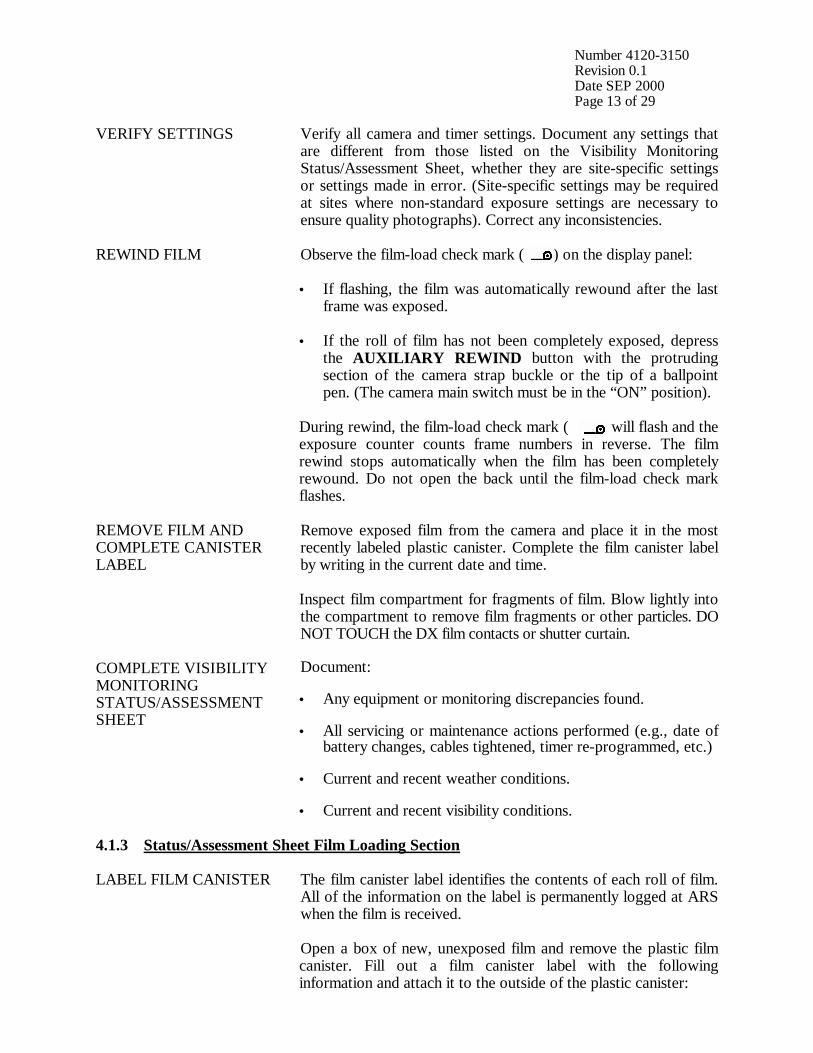
Number 4120-3150 Revision 0.1 Date SEP 2000 Page 13 of 29
VERIFY SETTINGS Verify all camera and timer settings. Document any settings that are different from those listed on the Visibility Monitoring Status/Assessment Sheet, whether they are site-specific settings or settings made in error. (Site-specific settings may be required at sites where non-standard exposure settings are necessary to ensure quality photographs). Correct any inconsistencies.
REWIND FILM Observe the film-load check mark ( ) on the display panel: • If flashing, the film was automatically rewound after the last
frame was exposed.
• If the roll of film has not been completely exposed, depress the AUXILIARY REWIND button with the protruding section of the camera strap buckle or the tip of a ballpoint pen. (The camera main switch must be in the “ON” position).
During rewind, the film-load check mark ( ) will flash and the exposure counter counts frame numbers in reverse. The film rewind stops automatically when the film has been completely rewound. Do not open the back until the film-load check mark flashes.
REMOVE FILM AND COMPLETE CANISTER LABEL
Remove exposed film from the camera and place it in the most recently labeled plastic canister. Complete the film canister label by writing in the current date and time. Inspect film compartment for fragments of film. Blow lightly into the compartment to remove film fragments or other particles. DO NOT TOUCH the DX film contacts or shutter curtain.
COMPLETE VISIBILITY MONITORING STATUS/ASSESSMENT SHEET
Document: • Any equipment or monitoring discrepancies found.
• All servicing or maintenance actions performed (e.g., date of battery changes, cables tightened, timer re-programmed, etc.)
• Current and recent weather conditions.
• Current and recent visibility conditions.
4.1.3 Status/Assessment Sheet Film Loading Section LABEL FILM CANISTER
The film canister label identifies the contents of each roll of film. All of the information on the label is permanently logged at ARS when the film is received. Open a box of new, unexposed film and remove the plastic film canister. Fill out a film canister label with the following information and attach it to the outside of the plastic canister:
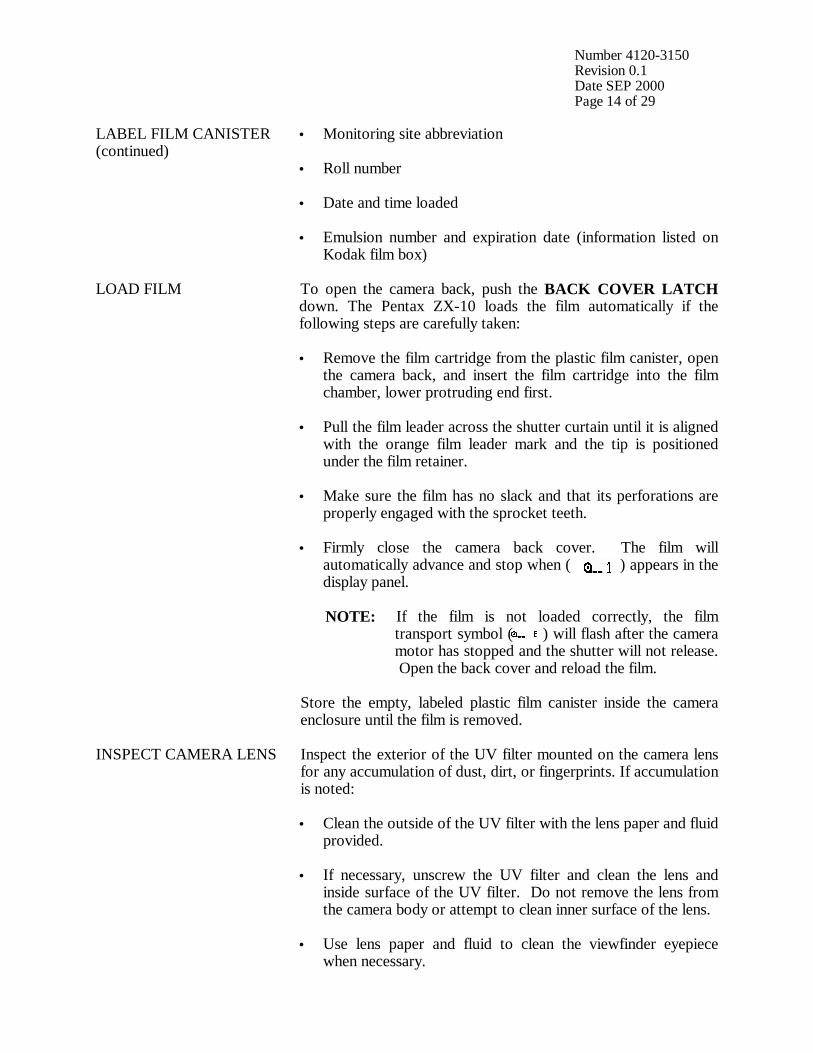
Number 4120-3150 Revision 0.1 Date SEP 2000 Page 14 of 29
LABEL FILM CANISTER (continued)
• Monitoring site abbreviation
• Roll number
• Date and time loaded
• Emulsion number and expiration date (information listed on Kodak film box)
LOAD FILM To open the camera back, push the BACK COVER LATCH
down. The Pentax ZX-10 loads the film automatically if the following steps are carefully taken: • Remove the film cartridge from the plastic film canister, open
the camera back, and insert the film cartridge into the film chamber, lower protruding end first.
• Pull the film leader across the shutter curtain until it is aligned with the orange film leader mark and the tip is positioned under the film retainer.
• Make sure the film has no slack and that its perforations are properly engaged with the sprocket teeth.
• Firmly close the camera back cover. The film will automatically advance and stop when ( ) appears in the display panel.
NOTE: If the film is not loaded correctly, the film
transport symbol ( ) will flash after the camera motor has stopped and the shutter will not release. Open the back cover and reload the film.
Store the empty, labeled plastic film canister inside the camera enclosure until the film is removed.
INSPECT CAMERA LENS Inspect the exterior of the UV filter mounted on the camera lens for any accumulation of dust, dirt, or fingerprints. If accumulation is noted: • Clean the outside of the UV filter with the lens paper and fluid
provided.
• If necessary, unscrew the UV filter and clean the lens and inside surface of the UV filter. Do not remove the lens from the camera body or attempt to clean inner surface of the lens.
• Use lens paper and fluid to clean the viewfinder eyepiece when necessary.
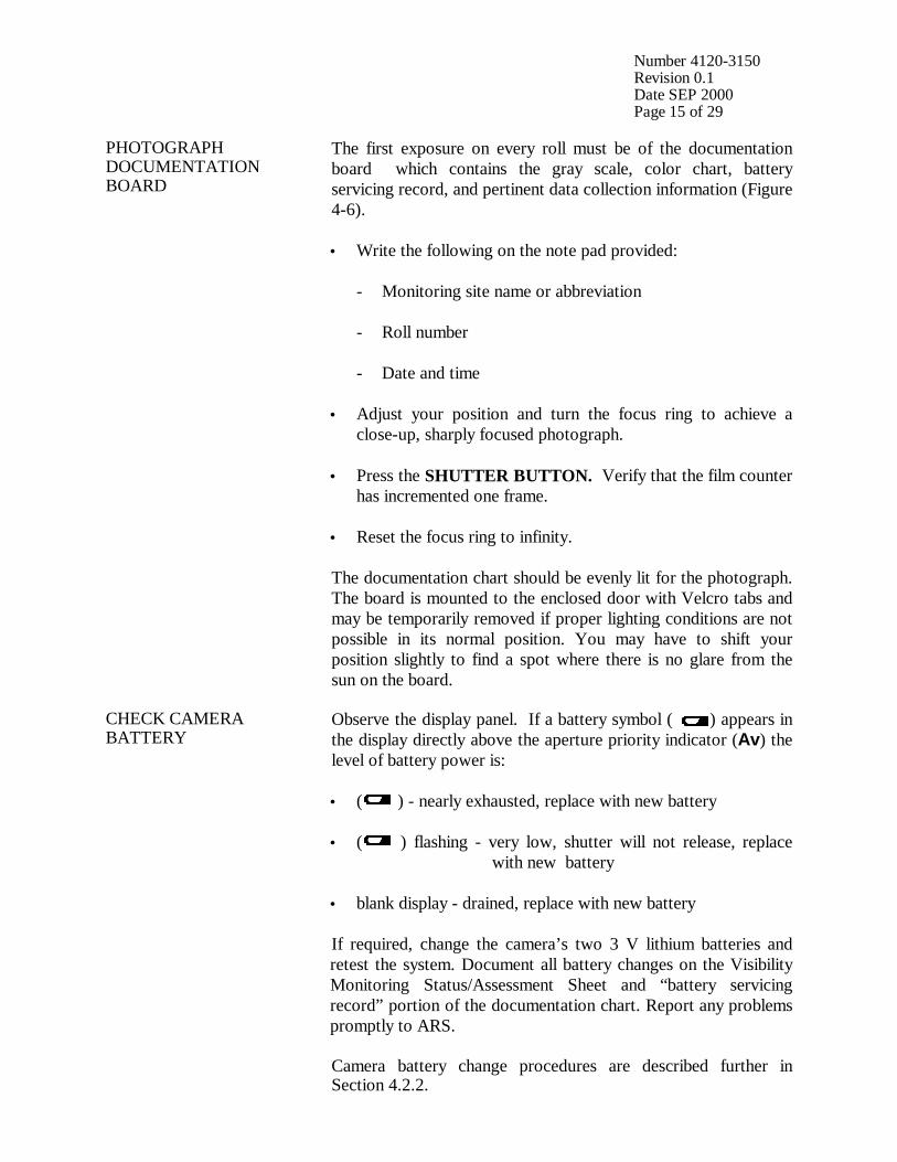
Number 4120-3150 Revision 0.1 Date SEP 2000 Page 15 of 29
PHOTOGRAPH DOCUMENTATION BOARD
The first exposure on every roll must be of the documentation board which contains the gray scale, color chart, battery servicing record, and pertinent data collection information (Figure 4-6). • Write the following on the note pad provided: - Monitoring site name or abbreviation - Roll number - Date and time • Adjust your position and turn the focus ring to achieve a
close-up, sharply focused photograph.
• Press the SHUTTER BUTTON. Verify that the film counter has incremented one frame.
• Reset the focus ring to infinity. The documentation chart should be evenly lit for the photograph. The board is mounted to the enclosed door with Velcro tabs and may be temporarily removed if proper lighting conditions are not possible in its normal position. You may have to shift your position slightly to find a spot where there is no glare from the sun on the board.
CHECK CAMERA BATTERY
Observe the display panel. If a battery symbol ( ) appears in the display directly above the aperture priority indicator (Av) the level of battery power is: • ( ) - nearly exhausted, replace with new battery
• ( ) flashing - very low, shutter will not release, replace
with new battery
• blank display - drained, replace with new battery If required, change the camera’s two 3 V lithium batteries and retest the system. Document all battery changes on the Visibility Monitoring Status/Assessment Sheet and “battery servicing record” portion of the documentation chart. Report any problems promptly to ARS. Camera battery change procedures are described further in Section 4.2.2.
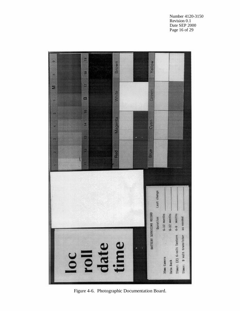
Number 4120-3150 Revision 0.1 Date SEP 2000 Page 16 of 29
Figure 4-6. Photographic Documentation Board.
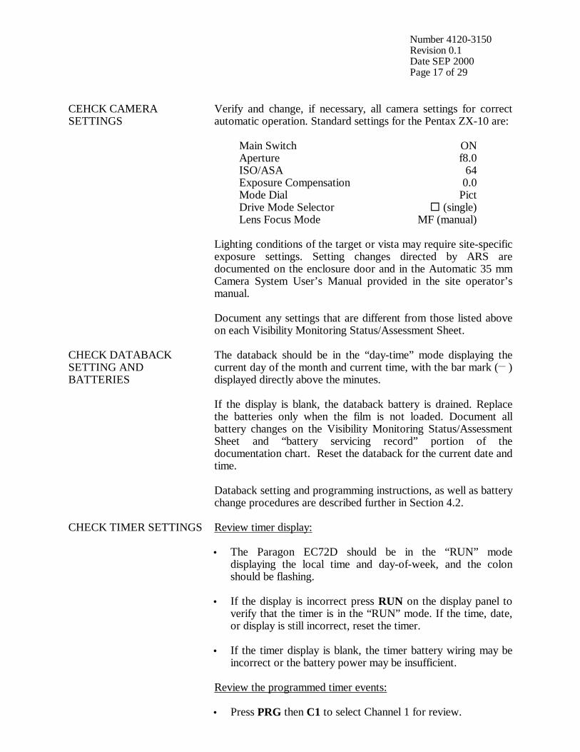
Number 4120-3150 Revision 0.1 Date SEP 2000 Page 17 of 29
CEHCK CAMERA SETTINGS
Verify and change, if necessary, all camera settings for correct automatic operation. Standard settings for the Pentax ZX-10 are: Main Switch ON Aperture f8.0 ISO/ASA 64 Exposure Compensation 0.0 Mode Dial Pict Drive Mode Selector ! (single) Lens Focus Mode MF (manual) Lighting conditions of the target or vista may require site-specific exposure settings. Setting changes directed by ARS are documented on the enclosure door and in the Automatic 35 mm Camera System User’s Manual provided in the site operator’s manual. Document any settings that are different from those listed above on each Visibility Monitoring Status/Assessment Sheet.
CHECK DATABACK SETTING AND BATTERIES
The databack should be in the “day-time” mode displaying the current day of the month and current time, with the bar mark (__ ) displayed directly above the minutes. If the display is blank, the databack battery is drained. Replace the batteries only when the film is not loaded. Document all battery changes on the Visibility Monitoring Status/Assessment Sheet and “battery servicing record” portion of the documentation chart. Reset the databack for the current date and time. Databack setting and programming instructions, as well as battery change procedures are described further in Section 4.2.
CHECK TIMER SETTINGS
Review timer display: • The Paragon EC72D should be in the “RUN” mode
displaying the local time and day-of-week, and the colon should be flashing.
• If the display is incorrect press RUN on the display panel to verify that the timer is in the “RUN” mode. If the time, date, or display is still incorrect, reset the timer.
• If the timer display is blank, the timer battery wiring may be incorrect or the battery power may be insufficient.
Review the programmed timer events:
• Press PRG then C1 to select Channel 1 for review.
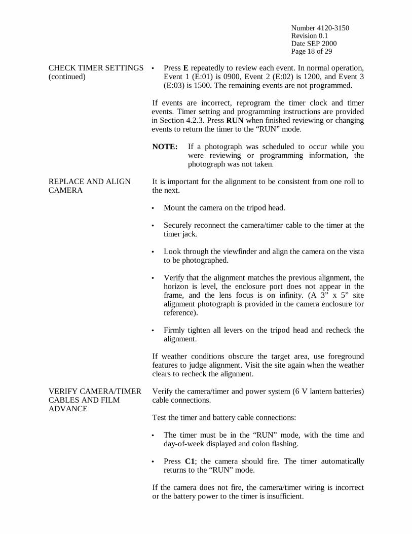
Number 4120-3150 Revision 0.1 Date SEP 2000 Page 18 of 29
CHECK TIMER SETTINGS (continued)
• Press E repeatedly to review each event. In normal operation, Event 1 (E:01) is 0900, Event 2 (E:02) is 1200, and Event 3 (E:03) is 1500. The remaining events are not programmed.
If events are incorrect, reprogram the timer clock and timer events. Timer setting and programming instructions are provided in Section 4.2.3. Press RUN when finished reviewing or changing events to return the timer to the “RUN” mode. NOTE: If a photograph was scheduled to occur while you
were reviewing or programming information, the photograph was not taken.
REPLACE AND ALIGN CAMERA
It is important for the alignment to be consistent from one roll to the next. • Mount the camera on the tripod head.
• Securely reconnect the camera/timer cable to the timer at the timer jack.
• Look through the viewfinder and align the camera on the vista to be photographed.
• Verify that the alignment matches the previous alignment, the horizon is level, the enclosure port does not appear in the frame, and the lens focus is on infinity. (A 3” x 5” site alignment photograph is provided in the camera enclosure for reference).
• Firmly tighten all levers on the tripod head and recheck the
alignment. If weather conditions obscure the target area, use foreground features to judge alignment. Visit the site again when the weather clears to recheck the alignment.
VERIFY CAMERA/TIMER CABLES AND FILM ADVANCE
Verify the camera/timer and power system (6 V lantern batteries) cable connections. Test the timer and battery cable connections: • The timer must be in the “RUN” mode, with the time and
day-of-week displayed and colon flashing.
• Press C1; the camera should fire. The timer automatically returns to the “RUN” mode.
If the camera does not fire, the camera/timer wiring is incorrect or the battery power to the timer is insufficient.
Number 4120-3150 Revision 0.1 Date SEP 2000 Page 19 of 29
VERIFY CAMERA/TIMER CABLES AND FILM ADVANCE (continued)
Test the camera/timer cable connection: • Gently shake the camera/timer cable leading into the camera
remote jack. If the camera fires, an electrical short may exist in a portion of the cable jack(s).
Document any discrepancies and/or corrective actions taken. Report any problems promptly to ARS.
DOCUMENT FINDINGS AND ACTIONS PERFORMED
Document any servicing or maintenance actions performed during the film loading process. Place the completed Visibility Monitoring Status/Assessment Sheet (yellow copy) in the Site Operator’s Manual for Automatic Visibility Monitoring Camera Systems.
CLOSE AND SECURE ENCLOSURE
Place the Site Operator’s Manual for Automatic Visibility Monitoring Camera Systems inside the camera enclosure for future reference. Close and lock the camera enclosure door. Tighten all door seal clamps and padlock the enclosure door hasp.
4.1.4 Mailing the Film and Completed Status/Assessment Sheet Place the original (white) copy of the Visibility Monitoring Status/Assessment Sheet and corresponding roll of film in a padded mailing envelope. Mail both the film and the Visibility Monitoring Status/Assessment Sheet immediately to: Air Resource Specialists, Inc. 1901 Sharp Point Drive, Suite E Fort Collins, CO 80525 Attention: Photographic Data Coordinator Call ARS immediately if any inconsistencies were noted or if any questions arise. Many problems can be resolved through telephone consultation. ARS may be reached at the following telephone numbers: Telephone: 970/484-7941 Fax: 970/484-3423 Detailed troubleshooting procedures to assist with telephone-directed problem resolution are presented in TI 4120-3350, Troubleshooting and Emergency Maintenance Procedures for 35 mm Automatic Camera System - Pentax ZX-10. 4.2 SCHEDULED MAINTENANCE Proper film storage and periodic preventive maintenance will help to ensure consistent, high quality data collection. Preventive maintenance servicing visits are performed as scheduled or required by the data coordinator.
Number 4120-3150 Revision 0.1 Date SEP 2000 Page 20 of 29
Scheduled maintenance normally consists of:
• Camera battery changes (every six months)
• Databack battery changes (annually)
• Timer battery changes (every six months) Replacement camera and timer batteries are provided by ARS with each film shipment (every six months). Replacement databack batteries are provided annually. Additional batteries will be provided as needed or as requested by the site operator. Test all batteries with a voltmeter before placing them in the system component. Verify all timer or camera battery malfunctions by testing removed component batteries with a voltmeter. Additional servicing tasks identified by the data coordinator may include:
• Camera, databack, and timer configuration checks or changes
• Camera alignment changes
• Revision of data collection procedures All scheduled maintenance requested by the data coordinator or performed by the site operator must be thoroughly documented on the Visibility Monitoring Status/Assessment Sheet and in the site-specific Quality Assurance Database. Any equipment malfunctions or data collection discrepancies observed during a scheduled maintenance visit should be reported to ARS immediately. The following subsections further describe proper methods for film storage, scheduled maintenance procedures, and corresponding servicing documentation. Troubleshooting and emergency maintenance procedures for the Pentax ZX-10 are provided in TI 4120-3350, Troubleshooting and Emergency Maintenance Procedures for 35 mm Automatic Camera System - Pentax ZX-10. 4.2.1 Film and Film Storage Only Kodachrome 64 slide film provided by ARS should be loaded into the visibility monitoring camera unless otherwise directed. Each roll of film has an emulsion number and expiration date. This information must be documented on the canister label of each exposed film roll (see Section 4.1.3). Photographic film is sensitive to heat and moisture. These elements can affect the film, altering both the processed photographs and the data analysis. For example, film subjected to heat often has a pink or purple cast while film subjected to moisture does not process consistently. To ensure proper film storage, keep the film inside a Ziploc bag with desiccant and place the bag inside the clearly labeled film storage box. The box should be stored in a freezer, refrigerator, or cool (less than 70°F), dry location. If stored in a freezer, allow film to thaw at room temperature for at least two hours before loading it in the camera.

Number 4120-3150 Revision 0.1 Date SEP 2000 Page 21 of 29
4.2.2 Changing System Batteries CAMERA BATTERY CHANGE
The Pentax ZX-10 camera runs on two 3 V lithium batteries. These batteries should be replaced every six months or as directed by the data coordinator. • Open the battery chamber cover by turning the cover lock
with a coin to the “open” position.
• Turn the camera upright and allow the batteries to slide out of the compartment. Measure and record the voltage of the used batteries.
• Remove the new batteries from their packaging and test and record the voltage. The new batteries should measure at least 3 volts each.
• Insert the new batteries and lock them in place by turning the battery chamber cover to the “close” position.
• After changing the batteries, check them as described in Section 4.1.3.
DATABACK BATTERY CHANGE
The Pentax Data Back runs on one 3 V coin-shaped lithium battery. The databack battery should be replaced annually, or as required by the data coordinator. Be sure to replace the battery only when film is not loaded. • The battery compartment is located on the inside of the
camera back cover. To open the compartment, use a small Phillips screwdriver and remove the screw on the battery chamber cover.
• Remove the battery. Measure and record the voltage of the used battery.
• Remove the new battery from its packaging and test and record the voltage. The new battery should measure approximately 3 volts.
• Wait 15 seconds after removing the used battery and then load the new battery with the “+” side facing up.
• Replace the battery chamber cover and tighten the fixing screw.
• Check the display and reset the databack for the current date and time as described in Section 4.1.3.
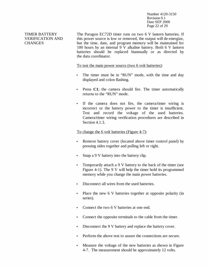
Number 4120-3150 Revision 0.1 Date SEP 2000 Page 22 of 29
TIMER BATTERY VERIFICATION AND CHANGES
The Paragon EC72D timer runs on two 6 V lantern batteries. If this power source is low or removed, the output will de-energize, but the time, date, and program memory will be maintained for 100 hours by an internal 9 V alkaline battery. Both 6 V lantern batteries should be replaced biannually or as directed by the data coordinator. To test the main power source (two 6 volt batteries): • The timer must be in “RUN” mode, with the time and day
displayed and colon flashing.
• Press C1; the camera should fire. The timer automatically returns to the “RUN” mode.
• If the camera does not fire, the camera/timer wiring is incorrect or the battery power to the timer is insufficient. Test and record the voltage of the used batteries. Camera/timer wiring verification procedures are described in Section 4.1.3.
To change the 6 volt batteries (Figure 4-7): • Remove battery cover (located above timer control panel) by
pressing sides together and pulling left or right.
• Snap a 9 V battery into the battery clip.
• Temporarily attach a 9 V battery to the back of the timer (see Figure 4-1). The 9 V will help the timer hold its programmed memory while you change the main power batteries.
• Disconnect all wires from the used batteries.
• Place the new 6 V batteries together at opposite polarity (in series).
• Connect the two 6 V batteries at one end.
• Connect the opposite terminals to the cable from the timer.
• Disconnect the 9 V battery and replace the battery cover.
• Perform the above test to assure the connections are secure.
• Measure the voltage of the new batteries as shown in Figure 4-7. The measurement should be approximately 12 volts.
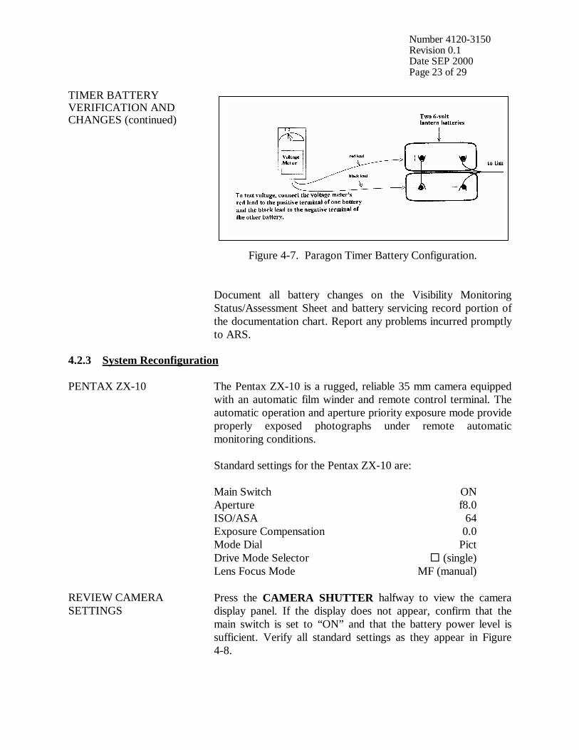
Number 4120-3150 Revision 0.1 Date SEP 2000 Page 23 of 29
TIMER BATTERY VERIFICATION AND CHANGES (continued)
Figure 4-7. Paragon Timer Battery Configuration. Document all battery changes on the Visibility Monitoring Status/Assessment Sheet and battery servicing record portion of the documentation chart. Report any problems incurred promptly to ARS.
4.2.3 System Reconfiguration PENTAX ZX-10 The Pentax ZX-10 is a rugged, reliable 35 mm camera equipped
with an automatic film winder and remote control terminal. The automatic operation and aperture priority exposure mode provide properly exposed photographs under remote automatic monitoring conditions. Standard settings for the Pentax ZX-10 are: Main Switch ON Aperture f8.0 ISO/ASA 64 Exposure Compensation 0.0 Mode Dial Pict Drive Mode Selector ! (single) Lens Focus Mode MF (manual)
REVIEW CAMERA SETTINGS
Press the CAMERA SHUTTER halfway to view the camera display panel. If the display does not appear, confirm that the main switch is set to “ON” and that the battery power level is sufficient. Verify all standard settings as they appear in Figure 4-8.
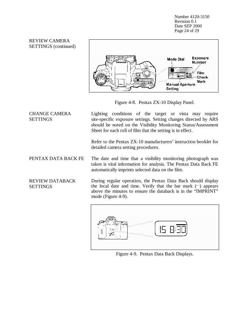
Number 4120-3150 Revision 0.1 Date SEP 2000 Page 24 of 29
REVIEW CAMERA SETTINGS (continued)
Figure 4-8. Pentax ZX-10 Display Panel.
CHANGE CAMERA SETTINGS
Lighting conditions of the target or vista may require site-specific exposure settings. Setting changes directed by ARS should be noted on the Visibility Monitoring Status/Assessment Sheet for each roll of film that the setting is in effect. Refer to the Pentax ZX-10 manufacturers’ instruction booklet for detailed camera setting procedures.
PENTAX DATA BACK FE The date and time that a visibility monitoring photograph was taken is vital information for analysis. The Pentax Data Back FE automatically imprints selected data on the film.
REVIEW DATABACK SETTINGS
During regular operation, the Pentax Data Back should display the local date and time. Verify that the bar mark (__) appears above the minutes to ensure the databack is in the “IMPRINT” mode (Figure 4-9).
Figure 4-9. Pentax Data Back Displays.
Number 4120-3150 Revision 0.1 Date SEP 2000 Page 25 of 29
REVIEW DATABACK SETTINGS (continued)
NOTE: Standard/Daylight-Saving Time Changes: Every spring and fall it will be necessary to change the databack clock to correspond with local standard or local daylight time. The data coordinator will provide a reminder postcard to document changes made.
To set the Pentax Data Back (use the protruding tip of the camera strap buckle): • Press the DATE button until the “DAY/HOUR/MINUTE”
mode is displayed.
• Press the SELECT button once -- the “HOUR” display will flash.
• Press the ADJUST button until the correct hour is displayed. Constant pressure on the “ADJUST” button will rapidly advance the numbers.
• Press the SELECT button -- the “MINUTES” display will flash. Press the ADJUST button until the correct minutes are displayed.
• Press the DATE button four times until the “YEAR/MONTH/DAY” mode is displayed.
• Press the SELECT button -- the “YEAR” display will flash. Press the ADJUST button until the correct year is displayed.
• Press the SELECT button -- the “MONTH” display will flash. Press the ADJUST button until the correct month is displayed.
• Press the SELECT button -- the “DAY” display will flash. Press the ADJUST button until the correct day is displayed.
• Press the DATE button once to return to the “DAY AND TIME” mode. A bar mark ( - ) should appear in the upper right corner of the display. This indicates the databack is in the “IMPRINTING” mode. The databack should remain in this mode during regular operation.
PARAGON EC72D TIMER
The Paragon automatic timer is normally programmed for three photographs a day at 0900, 1200, and 1500. If necessary, alternate sampling schedules can be programmed for 1 to 32 user-selected photographs a day. Routine servicing schedules are based on the number of photographs taken.

Number 4120-3150 Revision 0.1 Date SEP 2000 Page 26 of 29
PARAGON EC72D TIMER (continued)
• 3 photographs/day = 10-11 day servicing schedule.
• 2 photographs/day = 15-17 day servicing schedule.
• 1 photograph/day = 30-33 day servicing schedule. During regular operation the Paragon EC72D should be in the “RUN” mode displaying the local time and day-of-week (Sunday = 1; Saturday = 7) with the colon flashing.
SETTING THE PARAGON EC72D TIMER
To set the timer clock: • Wire power (two 6 V lantern batteries) to timer. A “0:00 1” is
displayed, with a colon and “1” flashing. Press CLK; the flashing stops.
• Using the 24-hour clock format, press four keys for the current time (e.g., 1015 = 10:15 a.m.). Press one key for the current date of the week; (1 = Sunday . . . 7 = Saturday). Press E to enter.
• “101” is displayed, indicating “January 1”. Press two keys for the current month and two keys for the current date (e.g., 0615 = June 15). Press E to enter.
• “84” is displayed, indicating “1984”. Press two keys for the current year (e.g., 90). Press E to enter. Control will automatically switch to the “RUN” mode. The time and day of week will be displayed with the colon flashing.
To program times for photographs to be taken: • Press PRG to enter “program” mode.
• Press C1 to select Channel 1 for programming; “E:01” (for
the first event) is displayed.
• Press four keys for the time the first photograph should be taken (e.g., 0900 for 9:00 a.m.). Press 0 to program the event to occur daily. Press E to enter the event into memory.
• The next event slot will be displayed (e.g., E:02). Repeat the step immediately above for each time of the day a photograph should be taken.
• Press RUN to return to “RUN” mode after all selected photograph times are programmed.
Procedures to review programmed timer events are provided in Section 4.1.3.
Number 4120-3150 Revision 0.1 Date SEP 2000 Page 27 of 29
SETTING THE PARAGON EC72D TIMER (continued)
NOTE: If more than 16 photographs per day are desired, Channel 2 may be used to program up to 16 additional events provided the Channel 2 output terminals have also been wired to the camera.
SITE-SPECIFIC CAMERA ALIGNMENT
Correct alignment of the camera is extremely important. Each photograph is compared to others of the same view during analysis. Therefore, alignment must remain constant from one roll of film to the next. A 3” x 5” site alignment photograph is provided for your reference in the camera enclosure. Alignment changes or adjustments may be necessary when: • Selected features are not properly framed in the view, and/or
• Exposure discrepancies result from intruding foreground or
backlit features. Any alignment change directed by ARS should be fully documented on the Visibility Monitoring Status/Assessment Sheet.
VERIFY CAMERA ALIGNMENT
Look through the viewfinder to verify the following: • The alignment matches the referenced site-specific alignment
photograph.
• The horizon is level.
• The vista is framed correctly.
• The sunshield and port are not visible in the viewfinder.
• The lens focus is on infinity. Document any misalignment found and assess probable cause on the Visibility Monitoring Status/Assessment Sheet. If weather conditions obscure the target area, use foreground features to judge alignment. Visit the site again when the weather clears to recheck the alignment. Procedures to ensure ongoing alignment are provided in TI 4120-3350, Troubleshooting and Emergency Maintenance Procedures for 35 mm Automatic Camera System - Pentax ZX-10.

Number 4120-3150 Revision 0.1 Date SEP 2000 Page 28 of 29
4.2.4 On-Site Data Control During each routine site visit, the operator documents maintenance performed and notes all discrepancies on the Visibility Monitoring Status/Assessment Sheet. The completed original (white copy) is mailed with each roll of film. A copy (yellow) is kept in the Site Operator’s Manual for Automatic Visibility Monitoring Camera Systems. If discrepancies or operator comments on the sheets indicate that further action is necessary, immediate corrective action is taken. Throughout the monitoring effort, ARS and site operators maintain close personal communications. Operators are encouraged to call or notify ARS if they have questions or problems. Ongoing review of film and site operator documentation often initiates corrective actions. Common data collection problems identified include:
• Roll number discrepancies
• Missing or improperly exposed documentation chart photographs
• Improper film loading or rewinding
• Late film changes
• Improper camera alignment
• Incorrect camera settings
• Weak or missing databack imprinting
• Incorrect timer settings
• Incomplete Visibility Monitoring Status/Assessment Sheet documentation All scheduled maintenance requested by the data coordinator or performed by the site operator must be thoroughly documented on the Visibility Monitoring Status/Assessment Sheet and in the site-specific Quality Assurance Database. If necessary, a Photographic Monitoring Network Quality Assessment Log (Figure 4-10) is mailed to the site to further document corrective actions taken. The site operator documents the date of correction and what was done, and returns a carbon copy of the log to ARS. Problems and equipment malfunctions requiring extensive troubleshooting and/or maintenance are fully described in TI 4120-3350.

Number 4120-3150 Revision 0.1 Date SEP 2000 Page 29 of 29
PHOTOGRAPHIC MONITORING NETWORK QUALITY ASSESSMENT LOG Site: __________________________ Date: ________________________________ _________________________ Operator: ______________________ From: _________________________ PROBLEM DESCRIPTION: ___________________________________________________________________________ ___________________________________________________________________________ ___________________________________________________________________________ ___________________________________________________________________________ ACTION REQUEST: ___________________________________________________________________________ ___________________________________________________________________________ ___________________________________________________________________________ ___________________________________________________________________________ ___________________________________________________________________________ ___________________________________________________________________________ ___________________________________________________________________________ ___________________________________________________________________________ CORRECTIVE ACTION TAKEN (to be completed by site operator): ___________________________________________________________________________ ___________________________________________________________________________ ___________________________________________________________________________ ___________________________________________________________________________ ___________________________________________________________________________ ___________________________________________________________________________ Date: _________________________ Operator: ________________________________
Return Yellow Copy To: White - Original, site copy Yellow - return to ARS Pink - ARS retain Figure 4-10. Photographic Monitoring Network Quality Assessment Log.
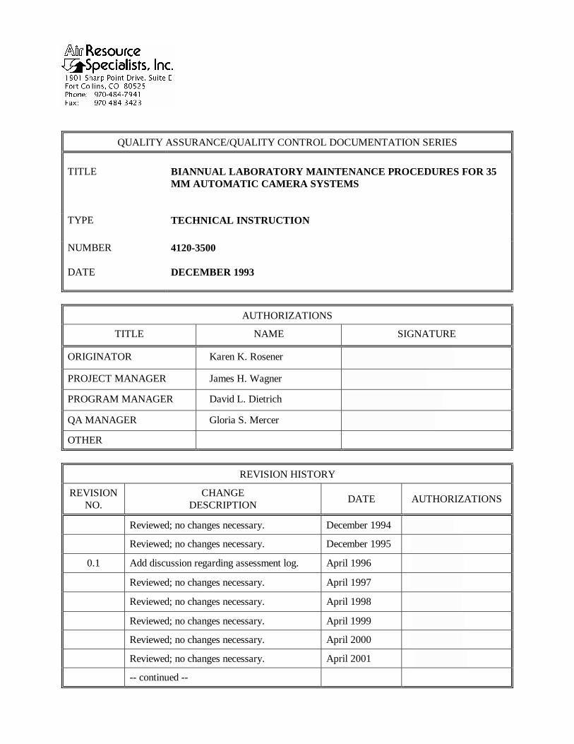
QUALITY ASSURANCE/QUALITY CONTROL DOCUMENTATION SERIES TITLE
BIANNUAL LABORATORY MAINTENANCE PROCEDURES FOR 35 MM AUTOMATIC CAMERA SYSTEMS
TYPE
TECHNICAL INSTRUCTION
NUMBER
4120-3500
DATE
DECEMBER 1993
AUTHORIZATIONS
TITLE NAME SIGNATURE
ORIGINATOR Karen K. Rosener
PROJECT MANAGER James H. Wagner
PROGRAM MANAGER David L. Dietrich
QA MANAGER Gloria S. Mercer
OTHER
REVISION HISTORY
REVISION NO.
CHANGE DESCRIPTION DATE AUTHORIZATIONS
Reviewed; no changes necessary. December 1994
Reviewed; no changes necessary. December 1995
0.1 Add discussion regarding assessment log. April 1996
Reviewed; no changes necessary. April 1997
Reviewed; no changes necessary. April 1998
Reviewed; no changes necessary. April 1999
Reviewed; no changes necessary. April 2000
Reviewed; no changes necessary. April 2001
-- continued --
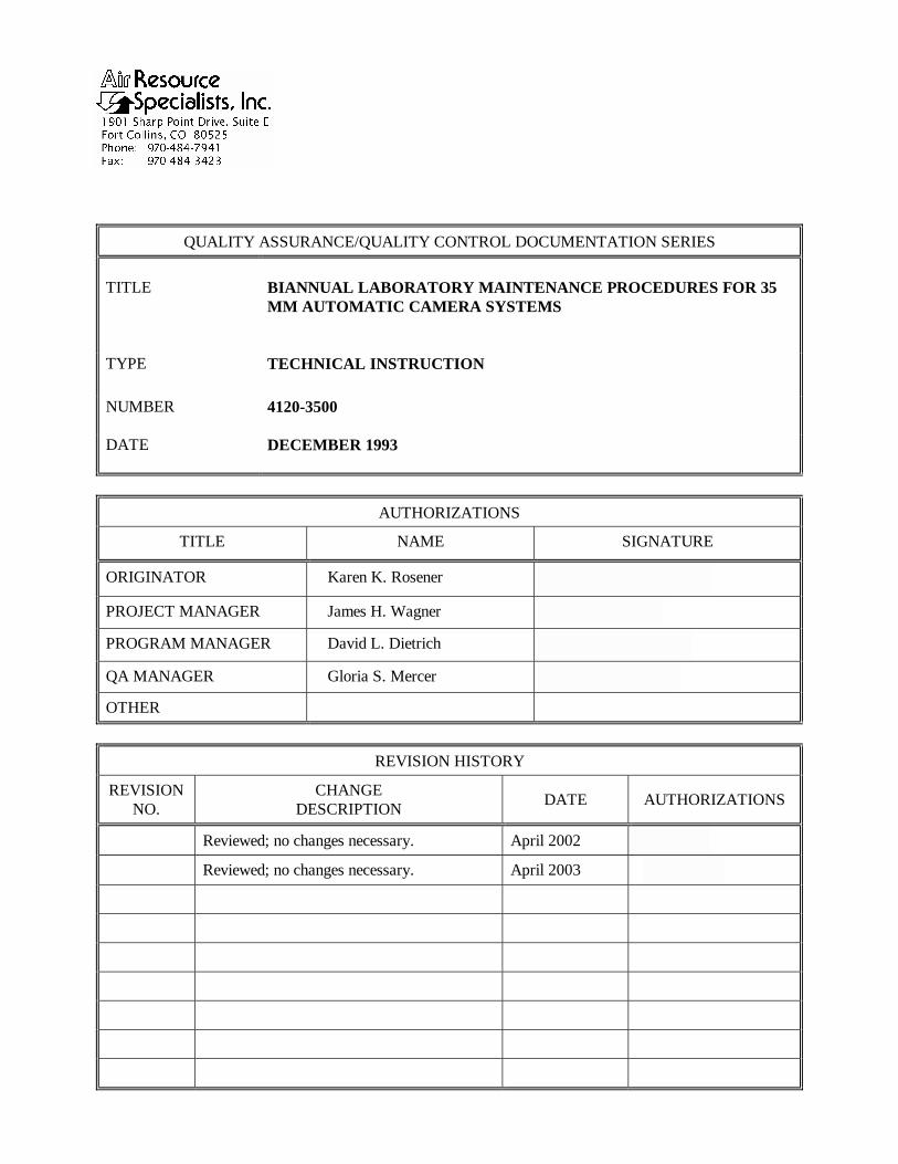
QUALITY ASSURANCE/QUALITY CONTROL DOCUMENTATION SERIES TITLE
BIANNUAL LABORATORY MAINTENANCE PROCEDURES FOR 35 MM AUTOMATIC CAMERA SYSTEMS
TYPE
TECHNICAL INSTRUCTION
NUMBER
4120-3500
DATE
DECEMBER 1993
AUTHORIZATIONS
TITLE NAME SIGNATURE
ORIGINATOR Karen K. Rosener
PROJECT MANAGER James H. Wagner
PROGRAM MANAGER David L. Dietrich
QA MANAGER Gloria S. Mercer
OTHER
REVISION HISTORY
REVISION NO.
CHANGE DESCRIPTION DATE AUTHORIZATIONS
Reviewed; no changes necessary. April 2002
Reviewed; no changes necessary. April 2003
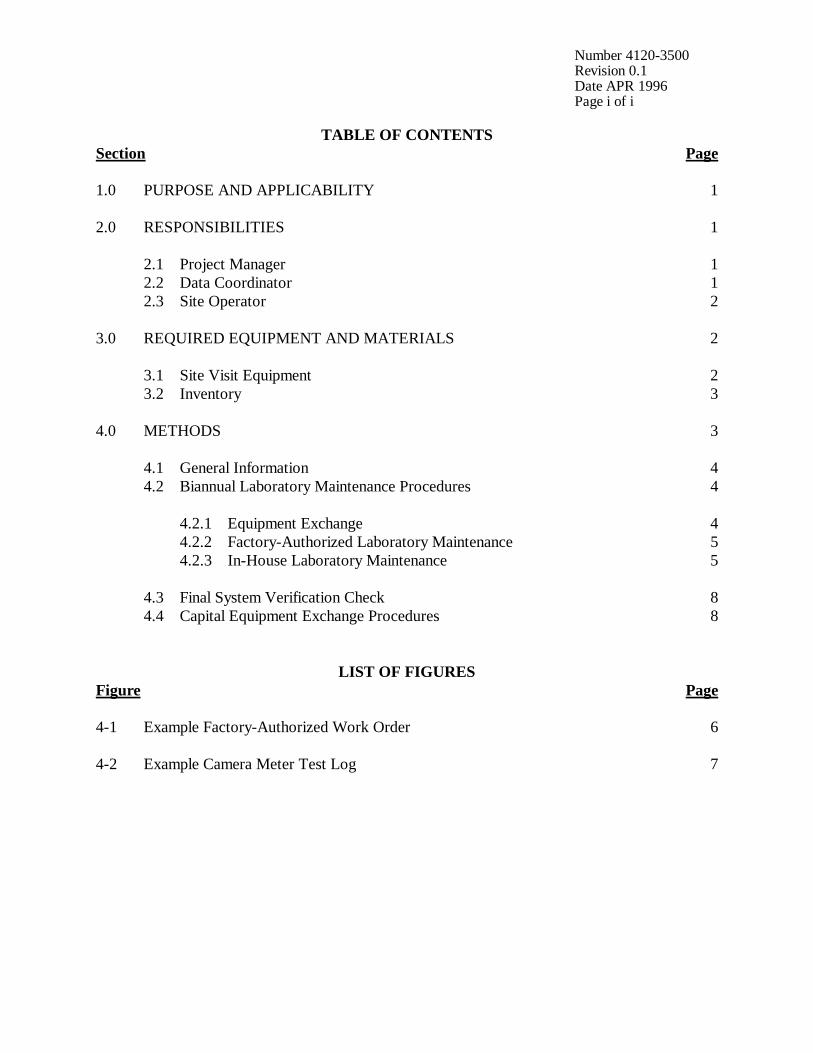
Number 4120-3500 Revision 0.1 Date APR 1996 Page i of i
TABLE OF CONTENTS Section Page 1.0 PURPOSE AND APPLICABILITY 1 2.0 RESPONSIBILITIES 1 2.1 Project Manager 1 2.2 Data Coordinator 1 2.3 Site Operator 2 3.0 REQUIRED EQUIPMENT AND MATERIALS 2 3.1 Site Visit Equipment 2 3.2 Inventory 3 4.0 METHODS 3 4.1 General Information 4 4.2 Biannual Laboratory Maintenance Procedures 4 4.2.1 Equipment Exchange 4 4.2.2 Factory-Authorized Laboratory Maintenance 5 4.2.3 In-House Laboratory Maintenance 5 4.3 Final System Verification Check 8 4.4 Capital Equipment Exchange Procedures 8
LIST OF FIGURES Figure Page 4-1 Example Factory-Authorized Work Order 6 4-2 Example Camera Meter Test Log 7
Number 4120-3500 Revision 0.1 Date APR 1996 Page 1 of 8
1.0 PURPOSE AND APPLICABILITY The purpose of biannual laboratory maintenance is to assure quality data capture and minimize data loss by performing maintenance procedures that will verify proper system operation and/or quickly identify the probable source of an automatic camera system malfunction. This technical instruction (TI) describes biannual laboratory maintenance procedures for 35 mm camera systems. Maintaining the visibility monitoring camera system includes preventive maintenance by a factory-authorized repair facility to ensure the system will continue to function properly. This TI is referenced in SOP 4120, Automatic Camera System Maintenance (IMPROVE Protocol) and serves as a guideline to facilitate the following scheduled maintenance tasks:
• Notification by the data coordinator that the biannual laboratory maintenance is due
• Installation of replacement camera system component(s)
• Mailing the original camera system to Air Resource Specialists, Inc. (ARS) for maintenance procedures
Site operators should be fully trained and supplied with a Site Operator’s Manual for Automatic Visibility Monitoring Camera Systems, which contains detailed routine site operator maintenance and troubleshooting procedures for the specific camera monitoring system(s) located at the site. Additional manufacturer’s instruction booklets and a supply of automatic camera system Visibility Monitoring Status/Assessment Sheets are also provided. Close personal communications should be maintained between ARS and site operators throughout all monitoring and scheduled maintenance efforts. Operators are encouraged to call or notify ARS if they have any questions or problems. Many problems can be fully resolved over the phone. 2.0 RESPONSIBILITIES 2.1 PROJECT MANAGER The project manager shall:
• Coordinate with the site operator, his/her supervisor, the field specialist, and the data coordinator concerning the schedule and requirements for biannual maintenance.
2.2 DATA COORDINATOR The data coordinator shall:
• Coordinate the replacement of camera systems.
• Coordinate all aspects of biannual camera maintenance.
• Enter all correspondence with site operators and the results of all performed procedures into the site-specific Quality Assurance Database.

Number 4120-3500 Revision 0.1 Date APR 1996 Page 2 of 8
• Document all capital instrumentation changes and maintain inventory records in the ARS Purchase Order/Inventory Database.
2.3 SITE OPERATOR The site operator shall:
• Perform all on-site procedures described in this TI.
• Thoroughly document all procedures on the Visibility Monitoring Status/Assessment Sheet and mail the white copy of the completed sheet to the data coordinator.
• Report any noted inconsistencies immediately to the data coordinator.
3.0 REQUIRED EQUIPMENT AND MATERIALS 3.1 SITE VISIT EQUIPMENT Equipment and materials generally required to remove the original camera system and install a replacement system include:
• Medium and small flat-blade screwdriver
• Small Phillips-head screwdriver
• Medium adjustable wrench
• Keys for enclosure and padlocks
• Voltmeter
• Backup camera and timer batteries
• Watch
• Site Operator’s Manual for Automatic Visibility Monitoring Camera Systems containing:
- SOP 4120, Automatic Camera System Maintenance (IMPROVE Protocol) - Technical instructions for routine site operator maintenance procedures - Technical instructions for troubleshooting and emergency maintenance procedures - Automatic 35 mm Camera System User’s Manual - Manufacturer’s instruction booklets - Visibility Monitoring Status/Assessment Sheets - Film canister labels
Number 4120-3500 Revision 0.1 Date APR 1996 Page 3 of 8
• Pen or pencil
• Grease pencil
• Supplemental visibility monitoring film 3.2 INVENTORY It is imperative that any capital instrumentation changes made as a result of biannual maintenance be thoroughly documented. Specific model and serial numbers of the exchanged camera body, lens, databack, and timer should be documented for future reference by the data coordinator in the site-specific Quality Assurance Database and ARS Purchase Order/Inventory Database. Any on-site changes made should be documented by the site operator on a Visibility Monitoring Status/Assessment Sheet or Photographic Monitoring Network Quality Assessment Log (described in Section 4.0). Capital equipment exchange procedures are discussed in Section 4.4. 4.0 METHODS This section includes four (4) major subsections: 4.1 General Information 4.2 Biannual Laboratory Maintenance Procedures 4.3 Final System Verification Check 4.4 Capital Equipment Exchange Procedures Maintaining a visibility monitoring camera system includes biannual laboratory maintenance to ensure the system continues to function properly. The biannual laboratory maintenance process should progress as outlined below to ensure ongoing, consistent data collection.
• The data coordinator contacts the site operator to inform him/her of the scheduled maintenance date.
• The data coordinator ships the replacement camera system along with a Photographic
Monitoring Network Quality Assessment Log. When received, the site operator exchanges the systems and ships the system in need of servicing to ARS, and documents the exchange on the log. The documentation should include:
- Date of installation - Steps taken to test system components - Current operational status
• All biannual laboratory maintenance communications documentation will be retained in the site-specific Quality Assurance Database for future reference.
A variety of automatic camera monitoring configurations exist. Specific equipment servicing and maintenance requirements for each site will vary with the system configuration.
Number 4120-3500 Revision 0.1 Date APR 1996 Page 4 of 8
4.1 GENERAL INFORMATION Internal quality assurance of automatic camera equipment is based primarily on visual review of processed visibility monitoring film. Film handling and review procedures are fully discussed in SOP 4305, Collection of Scene Monitoring Photographs and Film (IMPROVE Protocol). Alignment, exposure, and data collection efficiency can all be assessed from processed film. Operational camera systems are biannually cycled out of the monitoring network. Enclosures remain in place and the cameras and timers are cycled for laboratory maintenance. The laboratory maintenance ensures that the camera systems are in good working order, minimizing down time and data loss. Throughout the monitoring effort, ARS and site operators should maintain close personal communications. Site operators should call ARS immediately if any inconsistencies are noted or if any questions arise. Many problems can be resolved through telephone consultation. ARS may be reached at the following telephone numbers: Telephone: 970/484-7941 Fax: 970/484-3423 If the person you need to speak with is not in, ask to be directed to another or leave a message including your name, location, and a brief description of the problem(s) or need(s). 4.2 BIANNUAL LABORATORY MAINTENANCE PROCEDURES 4.2.1 Equipment Exchange The data coordinator will notify the site operator regarding the equipment exchange date. At that time, the specifics regarding replacement camera system installation and returning camera system shipping will be discussed. The current camera system at the site (including the camera, timer, and all cables) should be removed at the next site visit following receipt of a replacement system. Perform the following steps when reinstalling:
• Load a new roll of film in the replacement camera and verify that all settings are correct. A more detailed description of preparing a camera system is presented in the technical instructions for routine site operator maintenance procedures (appropriate for each camera model).
• After taking the documentation photograph, attach the camera-timer cable and mount on the tripod head.
• Attach the timer/battery cable. Program the timer to the correct settings.
• Verify that the system is working (see Section 4.3).
Number 4120-3500 Revision 0.1 Date APR 1996 Page 5 of 8
• Pack the camera system requiring servicing according to the data coordinator’s specifications.
• Ship the system to ARS. 4.2.2 Factory-Authorized Laboratory Maintenance Automatic camera system maintenance is normally provided by local factory-authorized repair facilities capable of performing the following:
• Completely disassembling and thoroughly cleaning the camera, including pivot points and shutter bearings
• Troubleshooting and repairing any noted problems so that the system fully meets or
exceeds the manufacturer’s specifications
• Relubricating to factory specifications and reassembling
• Testing shutter speed and curtain travel time at room temperature and 25°F
• Checking the meter readout and auto exposure
• Checking the diaphragm operation and film transport
• Testing electrical current consumption A work order accompanies each camera system to the factory-authorized repair facility. An example of a work order is presented as Figure 4-1. After repair, Camera Meter Test Logs are returned to ARS along with the camera system; an example Camera Meter Test Log is presented as Figure 4-2. 4.2.3 In-House Laboratory Maintenance The following tests are performed on timers and cables at ARS:
• Timer exteriors are visually inspected and cleaned.
• Timers are disassembled and the interiors visually inspected and cleaned.
• All solder points are checked.
• Replacement batteries are installed.
• A continuity test is performed on all cables with a voltmeter.
• A final system verification check is performed (see Section 4.3).
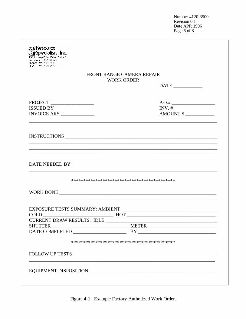
Number 4120-3500 Revision 0.1 Date APR 1996 Page 6 of 8
FRONT RANGE CAMERA REPAIR WORK ORDER
DATE ____________ PROJECT __________________ P.O.# __________________ ISSUED BY ________________ INV. # _________________ INVOICE ARS ______________ AMOUNT $ ____________ INSTRUCTIONS _______________________________________________________________ ______________________________________________________________________________ ______________________________________________________________________________ ______________________________________________________________________________ DATE NEEDED BY ____________________________________________________________ ______________________________________________________________________________
******************************************* WORK DONE _________________________________________________________________ ______________________________________________________________________________ EXPOSURE TESTS SUMMARY: AMBIENT _______________________________________ COLD _____________________________ HOT _____________________________________ CURRENT DRAW RESULTS: IDLE ______________________________________________ SHUTTER _______________________________ METER ____________________________ DATE COMPLETED ______________________ BY ________________________________
******************************************* FOLLOW UP TESTS ___________________________________________________________ _____________________________________________________________________________ EQUIPMENT DISPOSITION ____________________________________________________
Figure 4-1. Example Factory-Authorized Work Order.
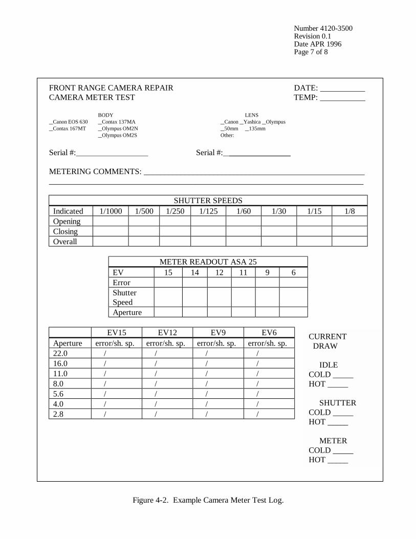
Number 4120-3500 Revision 0.1 Date APR 1996 Page 7 of 8
FRONT RANGE CAMERA REPAIR DATE: ___________ CAMERA METER TEST TEMP: ___________ BODY LENS Canon EOS 630 Contax 137MA Canon Yashica Olympus Contax 167MT Olympus OM2N 50mm 135mm Olympus OM2S Other: Serial #: Serial #: _______________ METERING COMMENTS: ______________________________________________________ _____________________________________________________________________________
SHUTTER SPEEDS Indicated 1/1000 1/500 1/250 1/125 1/60 1/30 1/15 1/8 Opening Closing Overall
METER READOUT ASA 25
EV 15 14 12 11 9 6 Error Shutter Speed
Aperture
EV15 EV12 EV9 EV6 Aperture error/sh. sp. error/sh. sp. error/sh. sp. error/sh. sp. 22.0 / / / / 16.0 / / / / 11.0 / / / / 8.0 / / / / 5.6 / / / / 4.0 / / / / 2.8 / / / /
Figure 4-2. Example Camera Meter Test Log.
CURRENT DRAW IDLE COLD _____ HOT _____ SHUTTER COLD _____ HOT _____ METER COLD _____ HOT _____
Number 4120-3500 Revision 0.1 Date APR 1996 Page 8 of 8
4.3 FINAL SYSTEM VERIFICATION CHECK A thorough review of all system components and camera settings is made following any system maintenance. The entire camera system is assembled, tested, and stored at ARS until needed. Refer to the technical instructions for routine site operator maintenance procedures for 35 mm automatic camera system (appropriate camera model), for complete system verification procedures. 4.4 CAPITAL EQUIPMENT EXCHANGE PROCEDURES It is imperative that any capital instrumentation changes made as a result of laboratory maintenance be thoroughly documented. The data coordinator should document the specific model and serial numbers of the enclosure, camera body, lens, databack, and automatic timer in the site-specific Quality Assurance Database and ARS Purchase Order/Inventory Database for future reference. The site operator should document any on-site changes made on a Visibility Monitoring Status/Assessment Sheet or Photographic Monitoring Network Quality Assessment Log.
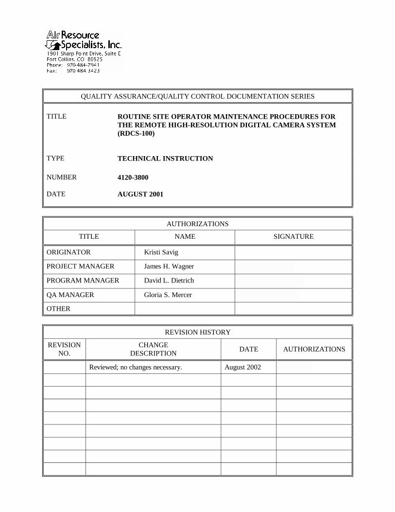
QUALITY ASSURANCE/QUALITY CONTROL DOCUMENTATION SERIES TITLE
ROUTINE SITE OPERATOR MAINTENANCE PROCEDURES FOR THE REMOTE HIGH-RESOLUTION DIGITAL CAMERA SYSTEM (RDCS-100)
TYPE
TECHNICAL INSTRUCTION
NUMBER
4120-3800
DATE
AUGUST 2001
AUTHORIZATIONS
TITLE NAME SIGNATURE
ORIGINATOR Kristi Savig
PROJECT MANAGER James H. Wagner
PROGRAM MANAGER David L. Dietrich
QA MANAGER Gloria S. Mercer
OTHER
REVISION HISTORY
REVISION NO.
CHANGE DESCRIPTION DATE AUTHORIZATIONS
Reviewed; no changes necessary. August 2002
Number 4120-3800 Revision 0 Date AUG 2001 Page i of ii
TABLE OF CONTENTS Section Page 1.0 PURPOSE AND APPLICABILITY 1 2.0 RESPONSIBILITIES 1 2.1 Project Manager 1 2.2 Field Specialist 1 2.3 Data Coordinator 2 2.4 Site Operator 2 3.0 REQUIRED EQUIPMENT AND MATERIALS 3 3.1 Site Visit Equipment 3 3.2 Inventory 4 4.0 METHODS 4 4.1 Routine Servicing 8 4.1.1 Status/Assessment Sheet General Information 11 4.1.2 Status/Assessment Sheet Memory Card Removed Section 12 4.1.3 Status/Assessment Sheet Memory Card Loaded Section 16 4.2 Scheduled Maintenance 19
LIST OF FIGURES Figure Page 4-1 Remote High-Resolution Digital Camera System (RDCS-100) Components 5 4-2 Remote High-Resolution Digital Camera System (RDCS-100) Mount Diagram 6 4-3 Remote High-Resolution Digital Camera System (RDCS-100) Enclosure 7 4-4 Example Remote Digital Camera System Visibility Monitoring Status/Assessment Sheet for the Remote High-Resolution Digital Camera System (RDCS-100) 9 4-5 Completed Example Remote Digital Camera System Visibility Monitoring Status/Assessment Sheet for the Remote High-Resolution Digital Camera System (RDCS-100) 10 4-6 FedEx Shipping Label With Tracking Number 11 4-7 PalmCam Menu 13
Number 4120-3800 Revision 0 Date AUG 2001 Page ii of ii
LIST OF FIGURES (CONTINUED) Figure Page 4-8 View Controller Status Menu 13 4-9 Memory Card Pouch Label 15 4-10 Exchange Memory Card Menu 18 4-11 Diagram of Proper Port Alignment 19 4-12 Photographic Monitoring Network Quality Assessment Log 21
LIST OF TABLES Table Page 4-1 Digital Camera System Field Maintenance Procedures 8
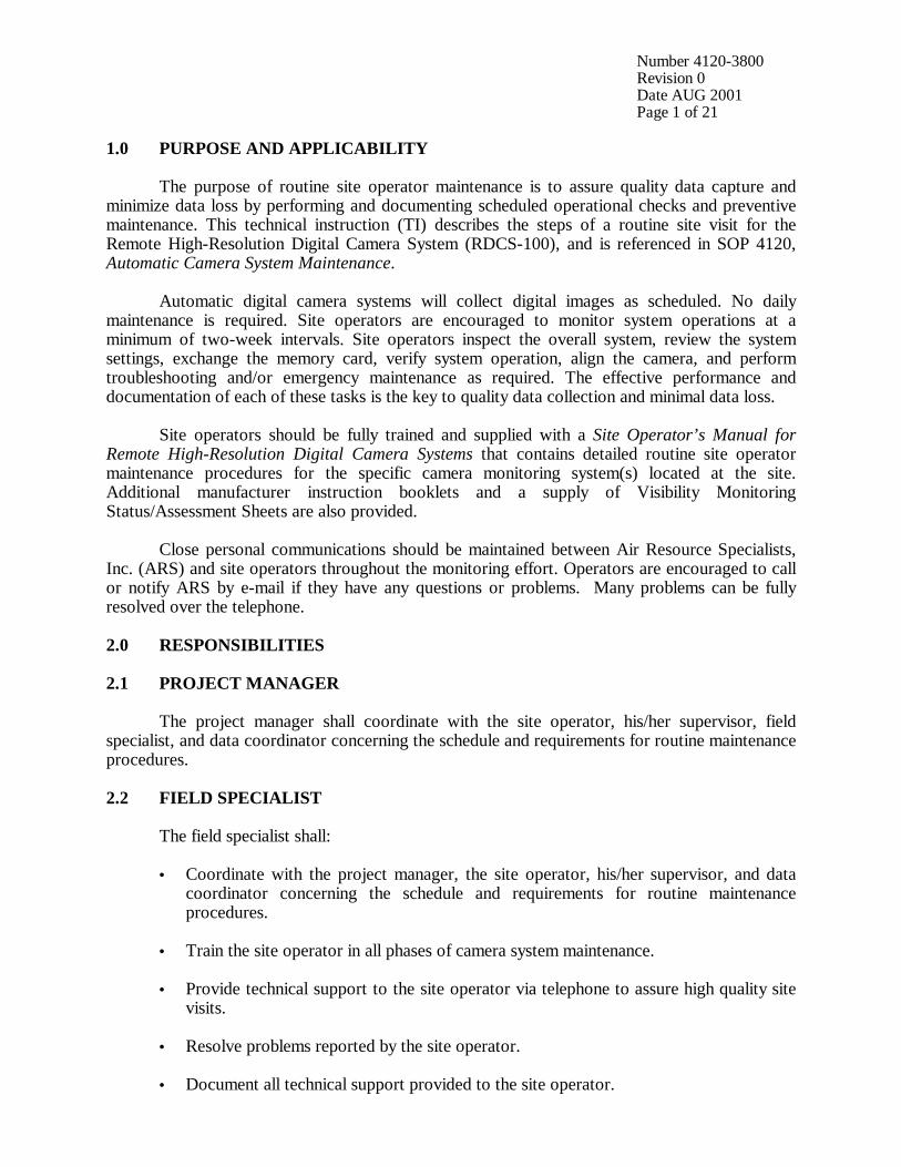
Number 4120-3800 Revision 0 Date AUG 2001 Page 1 of 21
1.0 PURPOSE AND APPLICABILITY The purpose of routine site operator maintenance is to assure quality data capture and minimize data loss by performing and documenting scheduled operational checks and preventive maintenance. This technical instruction (TI) describes the steps of a routine site visit for the Remote High-Resolution Digital Camera System (RDCS-100), and is referenced in SOP 4120, Automatic Camera System Maintenance. Automatic digital camera systems will collect digital images as scheduled. No daily maintenance is required. Site operators are encouraged to monitor system operations at a minimum of two-week intervals. Site operators inspect the overall system, review the system settings, exchange the memory card, verify system operation, align the camera, and perform troubleshooting and/or emergency maintenance as required. The effective performance and documentation of each of these tasks is the key to quality data collection and minimal data loss. Site operators should be fully trained and supplied with a Site Operator’s Manual for Remote High-Resolution Digital Camera Systems that contains detailed routine site operator maintenance procedures for the specific camera monitoring system(s) located at the site. Additional manufacturer instruction booklets and a supply of Visibility Monitoring Status/Assessment Sheets are also provided. Close personal communications should be maintained between Air Resource Specialists, Inc. (ARS) and site operators throughout the monitoring effort. Operators are encouraged to call or notify ARS by e-mail if they have any questions or problems. Many problems can be fully resolved over the telephone. 2.0 RESPONSIBILITIES 2.1 PROJECT MANAGER The project manager shall coordinate with the site operator, his/her supervisor, field specialist, and data coordinator concerning the schedule and requirements for routine maintenance procedures. 2.2 FIELD SPECIALIST The field specialist shall:
• Coordinate with the project manager, the site operator, his/her supervisor, and data coordinator concerning the schedule and requirements for routine maintenance procedures.
• Train the site operator in all phases of camera system maintenance. • Provide technical support to the site operator via telephone to assure high quality site
visits. • Resolve problems reported by the site operator. • Document all technical support provided to the site operator.
Number 4120-3800 Revision 0 Date AUG 2001 Page 2 of 21
2.3 DATA COORDINATOR The data coordinator shall:
• Coordinate with the project manager, the site operator, his/her supervisor, and field specialist concerning the schedule and requirements for routine maintenance procedures.
• Verify that scheduled visits are performed and notify the site operator if he/she fails to
make a scheduled visit. • Provide technical support to the site operator via telephone to identify and resolve
system problems. Document all technical support given to the site operator. • Coordinate the replacement and repair of all system components and support
hardware. • Supply the site operator with all necessary monitoring supplies. • Review all site documentation completed by the site operator for accuracy and
completeness. File all documentation and correspondence. • Enter the results of all performed procedures into the site-specific Quality Assurance
Database. • Document all capital instrumentation changes and maintain inventory records in the
ARS Purchase Order/Inventory Database. 2.4 SITE OPERATOR The site operator shall:
• Coordinate with his/her supervisor, the project manager, data coordinator, and field specialist concerning the schedule and requirements for routine maintenance procedures.
• Schedule regular site maintenance visits and perform all procedures described in this
TI. • Thoroughly document all procedures on the Visibility Monitoring Status/Assessment
Sheet; mail the white copy of the completed sheet to the data coordinator and maintain the yellow copy on site.
• Immediately report any noted inconsistencies to the data coordinator or field specialist.

Number 4120-3800 Revision 0 Date AUG 2001 Page 3 of 21
3.0 REQUIRED EQUIPMENT AND MATERIALS 3.1 SITE VISIT EQUIPMENT Equipment and materials generally required to support a routine site visit or scheduled maintenance include:
• Medium and small flat-blade screwdriver • Small Phillips-head screwdriver • Medium adjustable wrench • Keys for enclosure and padlocks • Spare camera batteries (4 AA Ni-MH) • Spare Personal Digital Assistant (PDA) batteries (2 AAA alkaline) • Paperclip for resetting the PDA • Voltmeter • Lens cleaner and lens paper • Site Operator’s Manual for Remote High-Resolution Digital Camera Systems,
containing:
- SOP 4120, Automatic Camera System Maintenance
- TI 4120-3800, Routine Site Operator Maintenance Procedures for the Remote High-Resolution Digital Camera System (RDCS-100)
- TI 4120-3900, Troubleshooting and Emergency Maintenance Procedures for the Remote High-Resolution Digital Camera System (RDCS-100)
- Manufacturer’s instruction booklets
- Visibility Monitoring Status/Assessment Sheets
• Pen or pencil • Memory card pouch with adhered label • Memory card shipping envelopes

Number 4120-3800 Revision 0 Date AUG 2001 Page 4 of 21
3.2 INVENTORY It is imperative that any capital instrumentation changes made as a result of routine maintenance be thoroughly documented. Specific model and serial numbers of the exchanged enclosure, camera, and/or Personal Digital Assistant (PDA) should be documented for future reference by the data coordinator in the site-specific Quality Assurance Database and ARS Purchase Order/Inventory Database. Any on-site changes made should be documented by the site operator on a Visibility Monitoring Status/Assessment Sheet or Photographic Monitoring Network Quality Assessment Log. Capital equipment exchange procedures are discussed in TI 4120-3900, Troubleshooting and Emergency Maintenance Procedures for the Remote High-Resolution Digital Camera System (RDCS-100). 4.0 METHODS All procedures described in this TI refer to the Remote High-Resolution Digital Camera System (RDCS-100), which consists of five major components:
• A high-resolution digital camera with zoom lens and integrated scripting • A custom-designed controller • A PDA (Personal Digital Assistant) palm computer interface • A battery-backed power system (AC or solar power) • A lockable environmental enclosure Many AC-powered remote high-resolution digital camera systems also contain a system
heater and window defroster kit. These supplemental components assure ongoing data collection and minimize window condensation for sites located in colder northern climates.
Routine servicing procedures are summarized in the Remote High-Resolution Digital
Camera System User’s Manual, provided in the site operator’s manual. Detailed photographs and diagrams of the system and associated components are provided in Figures 4-1 through 4-3. The following manufacturers’ instruction booklets provide additional reference and are located in the Site Operator's Manual for Remote High-Resolution Digital Camera Systems:
• Kodak digital camera instruction booklet • PDA palmtop computer instruction booklet
This section includes two (2) major subsections: 4.1 Routine Servicing
4.2 Scheduled Maintenance
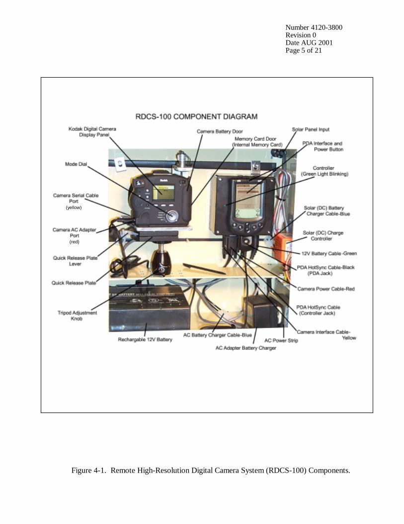
Number 4120-3800 Revision 0 Date AUG 2001 Page 5 of 21
Figure 4-1. Remote High-Resolution Digital Camera System (RDCS-100) Components.
(yellow)
(red)
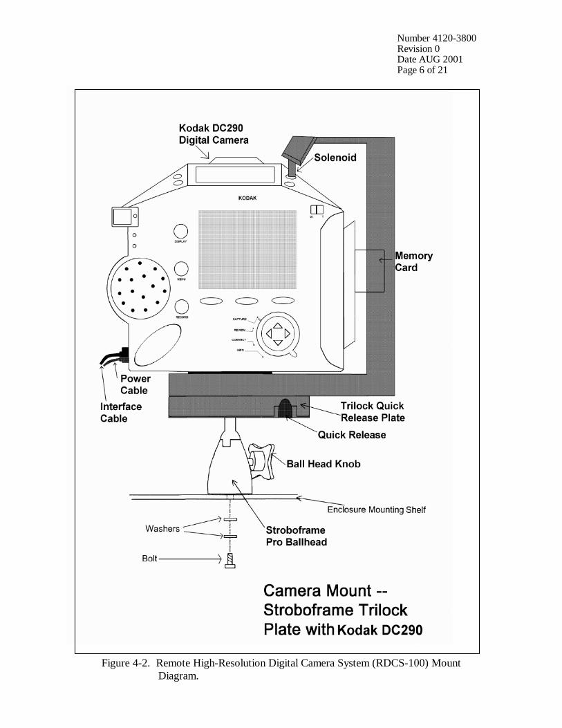
Number 4120-3800 Revision 0 Date AUG 2001 Page 6 of 21
Figure 4-2. Remote High-Resolution Digital Camera System (RDCS-100) Mount Diagram.
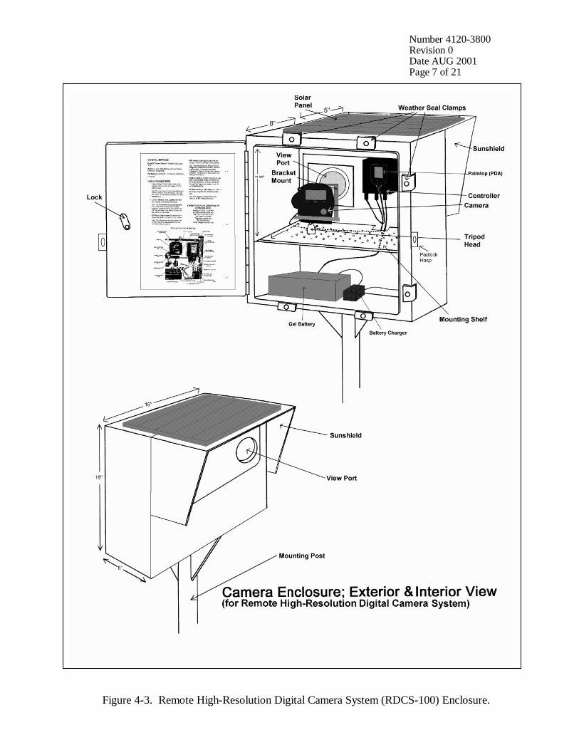
Number 4120-3800 Revision 0 Date AUG 2001 Page 7 of 21
Figure 4-3. Remote High-Resolution Digital Camera System (RDCS-100) Enclosure.
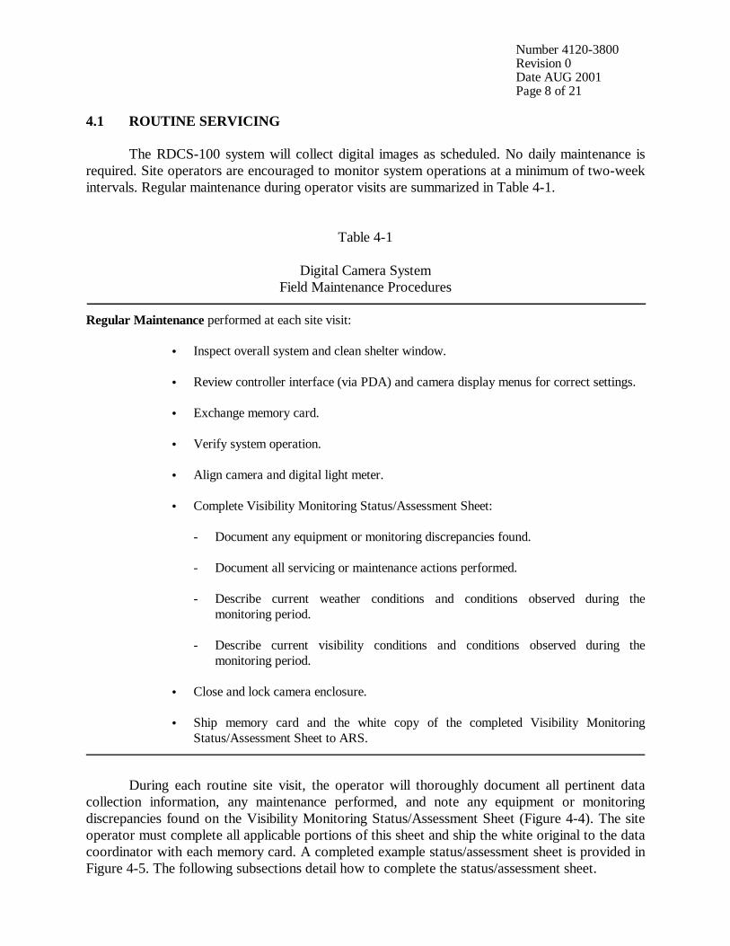
Number 4120-3800 Revision 0 Date AUG 2001 Page 8 of 21
4.1 ROUTINE SERVICING
The RDCS-100 system will collect digital images as scheduled. No daily maintenance is required. Site operators are encouraged to monitor system operations at a minimum of two-week intervals. Regular maintenance during operator visits are summarized in Table 4-1.
Table 4-1
Digital Camera System Field Maintenance Procedures
Regular Maintenance performed at each site visit:
• Inspect overall system and clean shelter window.
• Review controller interface (via PDA) and camera display menus for correct settings.
• Exchange memory card.
• Verify system operation.
• Align camera and digital light meter.
• Complete Visibility Monitoring Status/Assessment Sheet: - Document any equipment or monitoring discrepancies found. - Document all servicing or maintenance actions performed. - Describe current weather conditions and conditions observed during the
monitoring period. - Describe current visibility conditions and conditions observed during the
monitoring period.
• Close and lock camera enclosure. • Ship memory card and the white copy of the completed Visibility Monitoring
Status/Assessment Sheet to ARS. During each routine site visit, the operator will thoroughly document all pertinent data collection information, any maintenance performed, and note any equipment or monitoring discrepancies found on the Visibility Monitoring Status/Assessment Sheet (Figure 4-4). The site operator must complete all applicable portions of this sheet and ship the white original to the data coordinator with each memory card. A completed example status/assessment sheet is provided in Figure 4-5. The following subsections detail how to complete the status/assessment sheet.
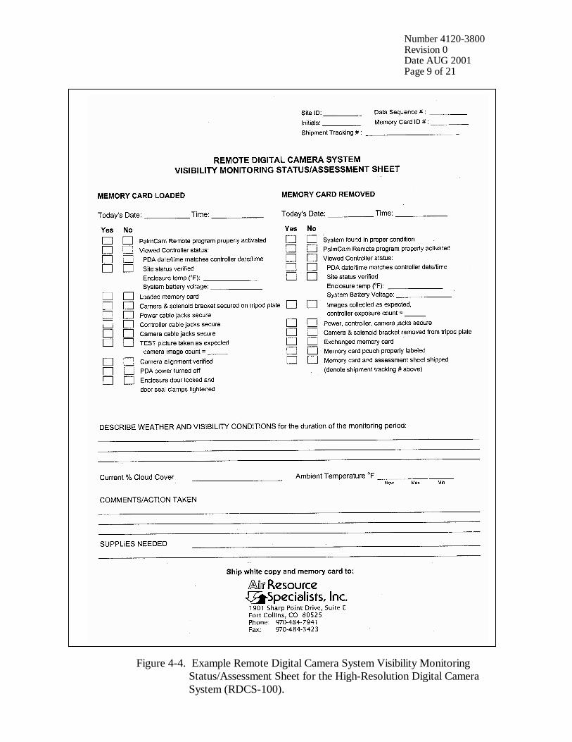
Number 4120-3800 Revision 0 Date AUG 2001 Page 9 of 21
Figure 4-4. Example Remote Digital Camera System Visibility Monitoring
Status/Assessment Sheet for the High-Resolution Digital Camera System (RDCS-100).
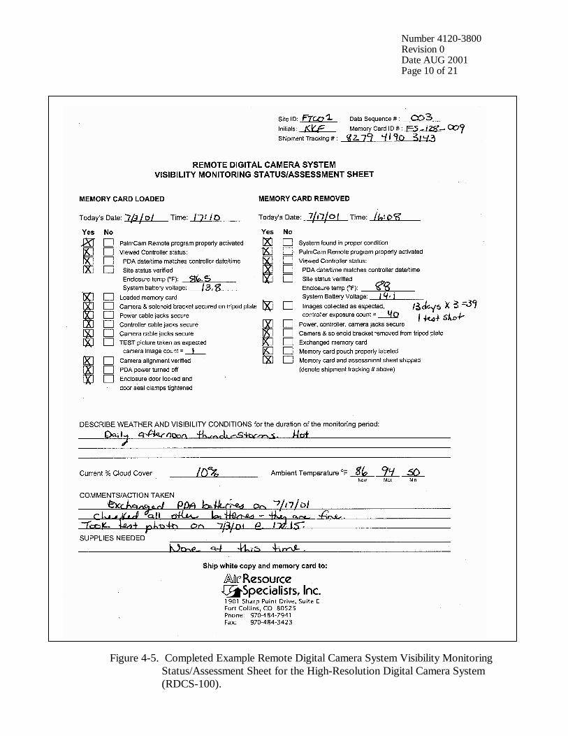
Number 4120-3800 Revision 0 Date AUG 2001 Page 10 of 21
Figure 4-5. Completed Example Remote Digital Camera System Visibility Monitoring
Status/Assessment Sheet for the High-Resolution Digital Camera System (RDCS-100).
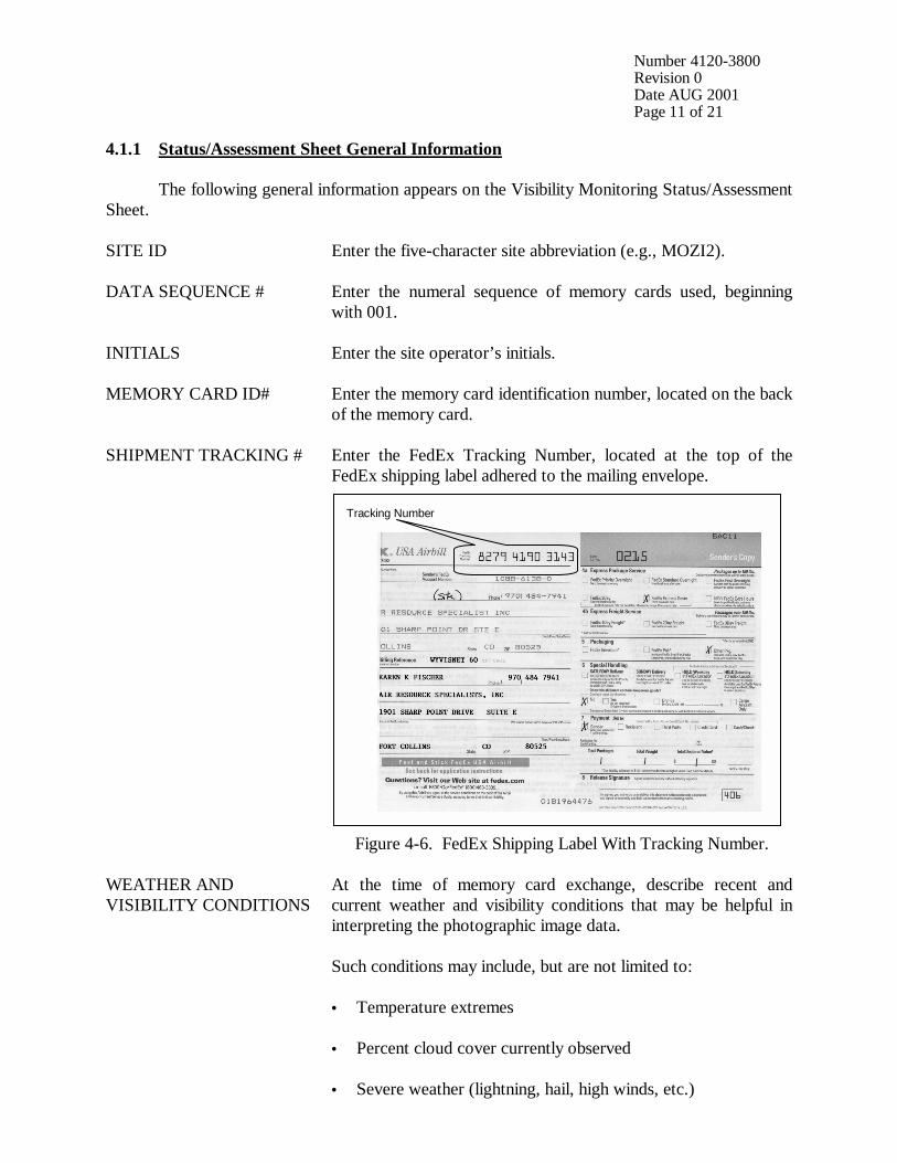
Number 4120-3800 Revision 0 Date AUG 2001 Page 11 of 21
4.1.1 Status/Assessment Sheet General Information The following general information appears on the Visibility Monitoring Status/Assessment Sheet. SITE ID Enter the five-character site abbreviation (e.g., MOZI2).
DATA SEQUENCE # Enter the numeral sequence of memory cards used, beginning
with 001.
INITIALS Enter the site operator’s initials.
MEMORY CARD ID# Enter the memory card identification number, located on the back of the memory card.
SHIPMENT TRACKING # Enter the FedEx Tracking Number, located at the top of the FedEx shipping label adhered to the mailing envelope.
Figure 4-6. FedEx Shipping Label With Tracking Number.
WEATHER AND VISIBILITY CONDITIONS
At the time of memory card exchange, describe recent and current weather and visibility conditions that may be helpful in interpreting the photographic image data. Such conditions may include, but are not limited to: • Temperature extremes • Percent cloud cover currently observed • Severe weather (lightning, hail, high winds, etc.)
Tracking Number
Number 4120-3800 Revision 0 Date AUG 2001 Page 12 of 21
WEATHER AND VISIBILITY CONDITIONS (continued)
• Passing storm fronts • Precipitation • Stagnant air masses • Fog • Extremely clean visibility conditions • Regional or layered haze • Plumes • Severity of haze • Emission source activity (e.g., nearby forest fires, controlled
burns, construction, dusty roads, residential wood burning, etc.)
• Any perceptible odors (e.g., wood smoke)
COMMENTS Describe any equipment or monitoring discrepancies found,
troubleshooting or scheduled maintenance performed, and/or corrective actions taken.
SUPPLIES NEEDED List any servicing supplies or documentation materials required for ongoing monitoring.
4.1.2 Status/Assessment Sheet Memory Card Removed Section DATE AND TIME Enter the date and time the memory card was removed and
servicing was performed.
SYSTEM FOUND IN PROPER CONDITION
Inspect the enclosure’s interior and exterior for damage or other problems (water leakage, dust, cable connections, window condensation, etc.).
Review the controller interface (on the PDA) and digital camera displays to verify that the system date, site code, zoom setting, image frequency, number of exposures taken, power, battery status, and other diagnostic information are properly recorded.

Number 4120-3800 Revision 0 Date AUG 2001 Page 13 of 21
PALMCAM REMOTE PROGRAM PROPERLY ACTIVATED
Verify that the PDA HotSync cable is properly inserted in the PDA jack. Activate the PDA interface by pressing the Power button (located at the top, center of the PDA). Access the PalmCam Remote program directly or through the Home menu (denoted by the symbol ). Note that the PDA will return to a sleep mode after 2 minutes with no use. To return to the current PalmCam Remote menu, press the PDA Power button again.
Figure 4-7. PalmCam Menu.
VIEWED CONTROLLER STATUS
Access the View Controller Status menu. (Allow 1 minute for all controller parameters to display).
Figure 4-8. View Controller Status Menu.
Power button
Date and Time PDA: 07/24/01 07:37:17
Controller: 07/24/01 07:37:17
Site: FRCW1 Zoom: 100
Temp: 84.4 Battery: 13.3
Prog: 9:00,12:00,15:00 Last Memory Card Change:
07/17/01 09:21:37 Refresh
Exposures: 28 Cancel
PalmCam – Controller Status:
Number 4120-3800 Revision 0 Date AUG 2001 Page 14 of 21
VIEWED CONTROLLER STATUS (continued)
• Verify and document the current Date and Time for both the PDA and controller. Differences below 1 minute are acceptable.
• Verify the proper site code, zoom settings, and program frequency (e.g., 3x/day).
• Document the displayed enclosure temperature and system battery supply voltage.
• Verify the date of last memory card exchange.
• Verify that the memory card pouch and Visibility Monitoring Status/Assessment Sheet are labeled with the proper exchange dates and times.
• Document the number of exposures recorded by the controller.
• Press the Cancel button to return to the PalmCam menu.
POWER, CONTROLLER, CAMERA JACKS SECURE
Visually inspect the 12 V battery, controller, and camera jacks to ensure they are secure. Check the integrity of the cables and component connectors. Document any problems, including broken connectors, loose or bare wires, etc. Report any problems promptly to ARS.
CAMERA & SOLENOID BRACKET REMOVED FROM TRIPOD PLATE
Remove the camera and solenoid bracket from the tripod plate to access the internal camera memory card. Memory card exchanges can be made at anytime, but two-week intervals are recommended for overall quality assurance. For a three-image per day schedule, the maximum number of days between service intervals would be approximately 90 days for a 128MB card at 1792 x 1200 image resolution. Press on the quick release plate lever (refer to Figure 4-2) and pull toward you. Remove the camera and solenoid bracket from the tripod release plate.
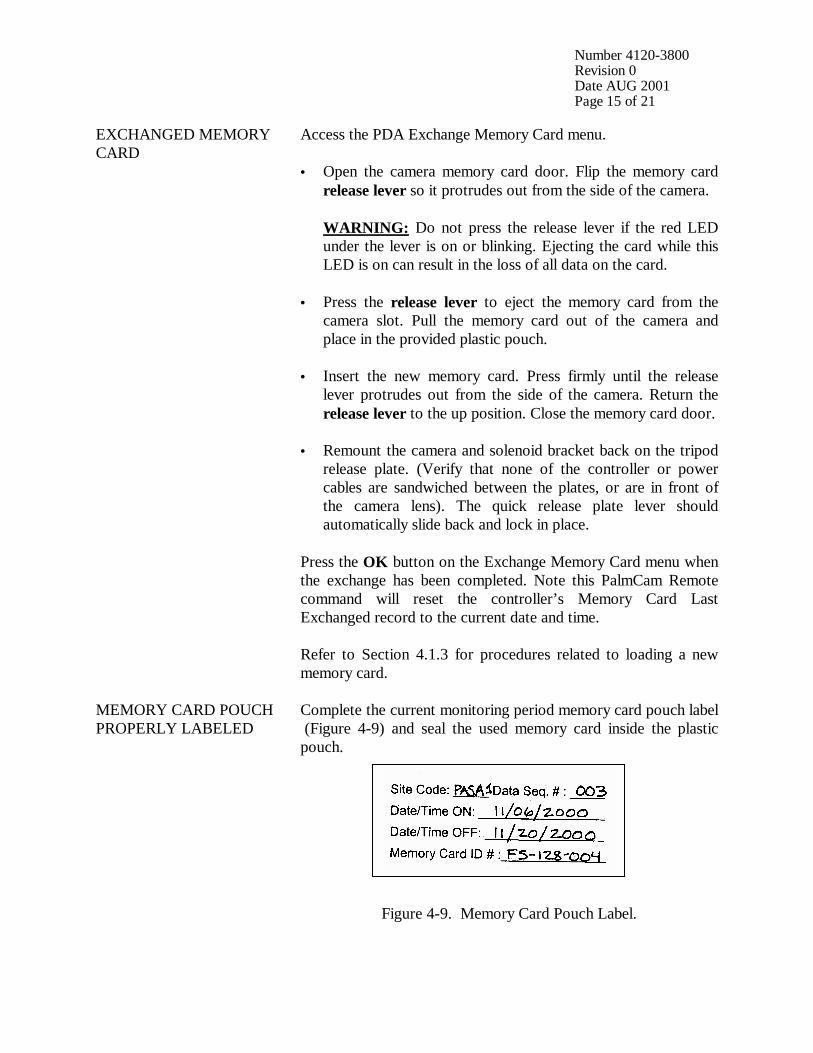
Number 4120-3800 Revision 0 Date AUG 2001 Page 15 of 21
EXCHANGED MEMORY CARD
Access the PDA Exchange Memory Card menu. • Open the camera memory card door. Flip the memory card
release lever so it protrudes out from the side of the camera. WARNING: Do not press the release lever if the red LED
under the lever is on or blinking. Ejecting the card while this LED is on can result in the loss of all data on the card.
• Press the release lever to eject the memory card from the
camera slot. Pull the memory card out of the camera and place in the provided plastic pouch.
• Insert the new memory card. Press firmly until the release
lever protrudes out from the side of the camera. Return the release lever to the up position. Close the memory card door.
• Remount the camera and solenoid bracket back on the tripod
release plate. (Verify that none of the controller or power cables are sandwiched between the plates, or are in front of the camera lens). The quick release plate lever should automatically slide back and lock in place.
Press the OK button on the Exchange Memory Card menu when the exchange has been completed. Note this PalmCam Remote command will reset the controller’s Memory Card Last Exchanged record to the current date and time. Refer to Section 4.1.3 for procedures related to loading a new memory card.
MEMORY CARD POUCH PROPERLY LABELED
Complete the current monitoring period memory card pouch label (Figure 4-9) and seal the used memory card inside the plastic pouch.
Figure 4-9. Memory Card Pouch Label.
Number 4120-3800 Revision 0 Date AUG 2001 Page 16 of 21
MEMORY CARD POUCH PROPERLY LABELED (continued)
Document the consecutive data sequence number and all observed settings (following the memory card exchange) on the Memory Card Loaded section of the new status/assessment sheet and on the new memory card pouch label. Place both the plastic pouch and new status/assessment sheet inside the enclosure door pocket.
MEMORY CARD AND ASSESSMENT SHEET SHIPPED
Insert the memory card pouch and the white copy of the Visibility Monitoring Status/Assessment Sheet inside the provided traceable shipping envelope. Complete the shipping label and document the tracking number on the site’s yellow copy of the status/assessment sheet (see Figure 4-6). Ship the data memory card to: Air Resource Specialists, Inc. 1901 Sharp Point Drive, Suite E Fort Collins, CO 80525 Attention: Photographic Data Coordinator Note that the operator can download the memory card to a local computer and immediately look at the images taken during the monitoring period. The image and associated data files could be electronically transferred to the operational collection center (via FTP) rather than shipping the memory card.
4.1.3 Status/Assessment Sheet Memory Card Loaded Section DATE AND TIME Enter the date and time the memory card was loaded and
servicing was performed.
Review the controller interface (on the PDA) and digital camera displays to verify that the system date, site code, zoom setting, image frequency, number of exposures taken, power, battery status, and other diagnostic information are properly recorded. PALMCAM REMOTE PROGRAM PROPERLY ACTIVATED
Activate the PDA interface by pressing the Power button. Access the PalmCam Remote program (refer to Figure 4-7) directly or through the Home menu (denoted by the symbol ). Note that the PDA will return to a sleep mode after 2 minutes with no use. To return to the current PalmCam Remote menu, press the PDA Power button again.
VIEWED CONTROLLER STATUS
Access the View Controller Status menu (refer to Figure 4-8). (Allow 1 minute for all controller parameters to display).
Number 4120-3800 Revision 0 Date AUG 2001 Page 17 of 21
VIEWED CONTROLLER STATUS (continued)
• Verify and document the current Date and Time for both the PDA and controller. Differences below 1 minute are acceptable.
• Verify the proper site code, zoom settings, and program
frequency (e.g., 3x/day). • Document the displayed enclosure temperature and system
battery supply voltage. • Verify the date of last memory card exchange. • Verify that the memory card pouch and Visibility Monitoring
Status/Assessment Sheet are labeled with the proper exchange dates and times.
• Press the Cancel button to return to the PalmCam menu.
LOADED MEMORY CARD
Load a newly formatted memory card into the camera. Refer to Section 4.1.2 for procedures.
CAMERA & SOLENOID BRACKET SECURED ON TRIPOD PLATE
Replace the camera and solenoid bracket on the tripod release plate. Ensure the quick release plate lever is secure (refer to Figure 4-2).
POWER CABLE JACKS SECURE
Visually inspect the power cable jacks and ensure they are secure. Check integrity of the cables and component connectors. Document any problems, including broken connectors, loose or bare wires, etc. Report any problems promptly to ARS.
CONTROLLER CABLE JACKS SECURE
Visually inspect the controller cable jacks and ensure they are secure. Check integrity of the cables and component connectors. Document any problems, including broken connectors, loose or bare wires, etc. Report any problems promptly to ARS.
CAMERA CABLE JACKS SECURE
Visually inspect the camera jacks and ensure they are secure. Check integrity of the cables and component connectors. Document any problems, including broken connectors, loose or bare wires, etc. Report any problems promptly to ARS.
TEST PICTURE TAKEN AS EXPECTED
Press the TEST button on the Exchange Memory Card menu to verify the camera alignment, that all wiring is correct, and the battery power is sufficient to run the camera system.
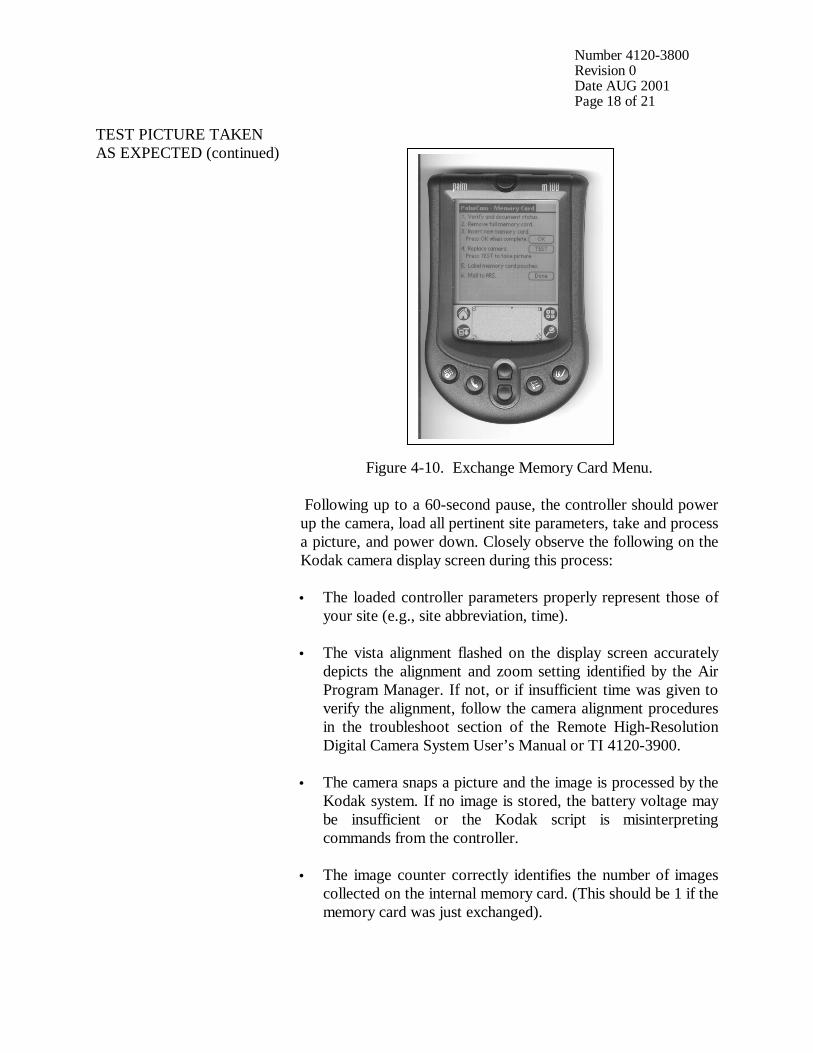
Number 4120-3800 Revision 0 Date AUG 2001 Page 18 of 21
TEST PICTURE TAKEN AS EXPECTED (continued)
Figure 4-10. Exchange Memory Card Menu.
Following up to a 60-second pause, the controller should power up the camera, load all pertinent site parameters, take and process a picture, and power down. Closely observe the following on the Kodak camera display screen during this process: • The loaded controller parameters properly represent those of
your site (e.g., site abbreviation, time).
• The vista alignment flashed on the display screen accurately depicts the alignment and zoom setting identified by the Air Program Manager. If not, or if insufficient time was given to verify the alignment, follow the camera alignment procedures in the troubleshoot section of the Remote High-Resolution Digital Camera System User’s Manual or TI 4120-3900.
• The camera snaps a picture and the image is processed by the
Kodak system. If no image is stored, the battery voltage may be insufficient or the Kodak script is misinterpreting commands from the controller.
• The image counter correctly identifies the number of images collected on the internal memory card. (This should be 1 if the memory card was just exchanged).
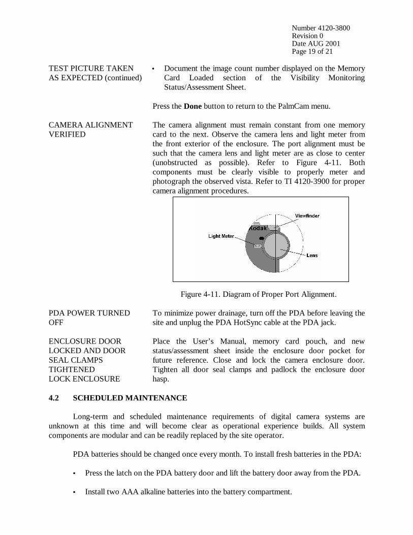
Number 4120-3800 Revision 0 Date AUG 2001 Page 19 of 21
TEST PICTURE TAKEN AS EXPECTED (continued)
• Document the image count number displayed on the Memory Card Loaded section of the Visibility Monitoring Status/Assessment Sheet.
Press the Done button to return to the PalmCam menu.
CAMERA ALIGNMENT VERIFIED
The camera alignment must remain constant from one memory card to the next. Observe the camera lens and light meter from the front exterior of the enclosure. The port alignment must be such that the camera lens and light meter are as close to center (unobstructed as possible). Refer to Figure 4-11. Both components must be clearly visible to properly meter and photograph the observed vista. Refer to TI 4120-3900 for proper camera alignment procedures.
Figure 4-11. Diagram of Proper Port Alignment.
PDA POWER TURNED OFF
To minimize power drainage, turn off the PDA before leaving the site and unplug the PDA HotSync cable at the PDA jack.
ENCLOSURE DOOR LOCKED AND DOOR SEAL CLAMPS TIGHTENED LOCK ENCLOSURE
Place the User’s Manual, memory card pouch, and new status/assessment sheet inside the enclosure door pocket for future reference. Close and lock the camera enclosure door. Tighten all door seal clamps and padlock the enclosure door hasp.
4.2 SCHEDULED MAINTENANCE
Long-term and scheduled maintenance requirements of digital camera systems are unknown at this time and will become clear as operational experience builds. All system components are modular and can be readily replaced by the site operator. PDA batteries should be changed once every month. To install fresh batteries in the PDA:
• Press the latch on the PDA battery door and lift the battery door away from the PDA. • Install two AAA alkaline batteries into the battery compartment.

Number 4120-3800 Revision 0 Date AUG 2001 Page 20 of 21
• Insert the battery door back into place so that it is flush with the back of the PDA and “clicks” into position. NOTE: When changing batteries, replace them quickly. The built-in backup power maintains memory of your data for a period of up to one minute.
All scheduled maintenance requested by the data coordinator or performed by the site operator must be thoroughly documented on the Visibility Monitoring Status/Assessment Sheet and in the site-specific Quality Assurance Database. If necessary, a Photographic Monitoring Network Quality Assessment Log (Figure 4-12) is mailed to the site to further document corrective actions taken. The site operator documents the date of correction and what was done, and returns a carbon copy or immediately faxes the log to ARS. Problems and equipment malfunctions requiring extensive troubleshooting and/or maintenance are fully described in TI 4120-3900, Troubleshooting and Emergency Maintenance Procedures for the Remote High-Resolution Digital Camera System (RDCS-100).
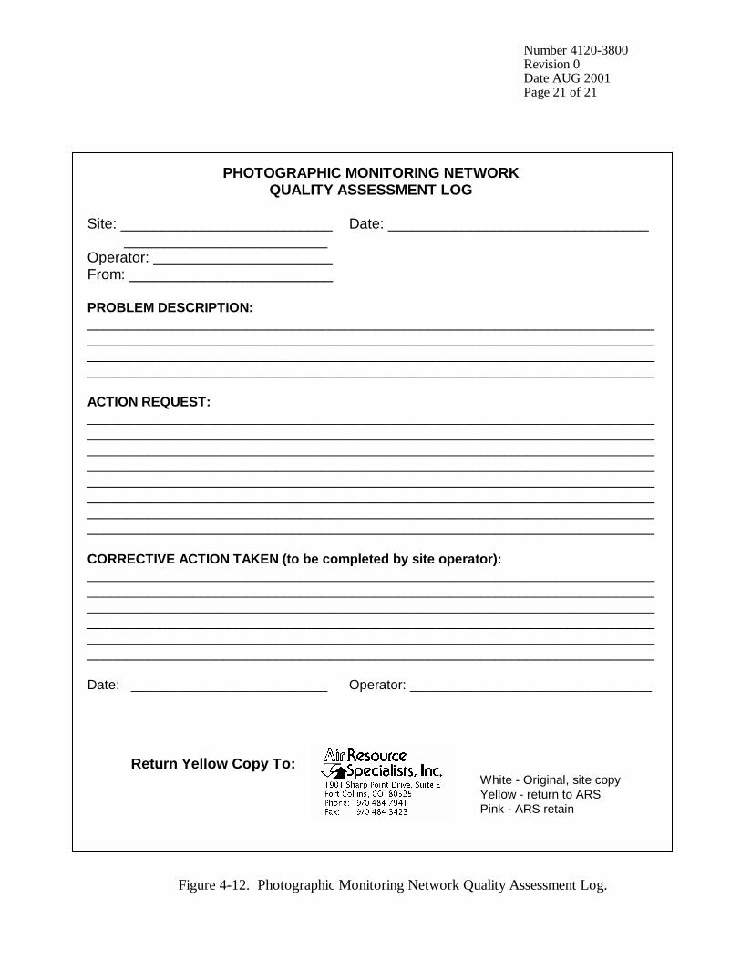
Number 4120-3800 Revision 0 Date AUG 2001 Page 21 of 21
PHOTOGRAPHIC MONITORING NETWORK QUALITY ASSESSMENT LOG
Site: __________________________ Date: ________________________________ _________________________ Operator: ______________________ From: _________________________ PROBLEM DESCRIPTION: ___________________________________________________________________________ ___________________________________________________________________________ ___________________________________________________________________________ ___________________________________________________________________________ ACTION REQUEST: ___________________________________________________________________________ ___________________________________________________________________________ ___________________________________________________________________________ ___________________________________________________________________________ ___________________________________________________________________________ ___________________________________________________________________________ ___________________________________________________________________________ ___________________________________________________________________________ CORRECTIVE ACTION TAKEN (to be completed by site operator): ___________________________________________________________________________ ___________________________________________________________________________ ___________________________________________________________________________ ___________________________________________________________________________ ___________________________________________________________________________ ___________________________________________________________________________ Date: __________________________ Operator: ________________________________ Return Yellow Copy To: White - Original, site copy Yellow - return to ARS Pink - ARS retain
Figure 4-12. Photographic Monitoring Network Quality Assessment Log.
QUALITY ASSURANCE/QUALITY CONTROL DOCUMENTATION SERIES TITLE
ROUTINE SITE OPERATOR MAINTENANCE PROCEDURES FOR THE HIGH-RESOLUTION DIGITAL CAMERA SYSTEM (HRDC)
TYPE
TECHNICAL INSTRUCTION
NUMBER
4120-3850
DATE
JULY 2003
AUTHORIZATIONS
TITLE NAME SIGNATURE
ORIGINATOR Karen Fischer
PROJECT MANAGER Scott Cismoski
PROGRAM MANAGER David L. Dietrich
QA MANAGER Gloria S. Mercer
OTHER
REVISION HISTORY
REVISION NO.
CHANGE DESCRIPTION DATE AUTHORIZATIONS
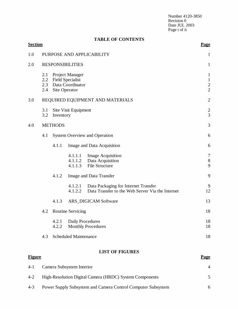
Number 4120-3850 Revision 0 Date JUL 2003 Page i of ii
TABLE OF CONTENTS Section Page 1.0 PURPOSE AND APPLICABILITY 1 2.0 RESPONSIBILITIES 1 2.1 Project Manager 1 2.2 Field Specialist 1 2.3 Data Coordinator 2 2.4 Site Operator 2 3.0 REQUIRED EQUIPMENT AND MATERIALS 2 3.1 Site Visit Equipment 2 3.2 Inventory 3 4.0 METHODS 3 4.1 System Overview and Operation 6 4.1.1 Image and Data Acquisition 6 4.1.1.1 Image Acquisition 7 4.1.1.2 Data Acquisition 8 4.1.1.3 File Structure 9 4.1.2 Image and Data Transfer 9 4.1.2.1 Data Packaging for Internet Transfer 9 4.1.2.2 Data Transfer to the Web Server Via the Internet 12 4.1.3 ARS_DIGICAM Software 13 4.2 Routine Servicing 18 4.2.1 Daily Procedures 18 4.2.2 Monthly Procedures 18 4.3 Scheduled Maintenance 18
LIST OF FIGURES Figure Page 4-1 Camera Subsystem Interior 4 4-2 High-Resolution Digital Camera (HRDC) System Components 5 4-3 Power Supply Subsystem and Camera Control Computer Subsystem 6
Number 4120-3850 Revision 0 Date JUL 2003 Page ii of ii
LIST OF FIGURES (CONTINUED) Figure Page 4-4 Example ARS_DIGICAM.INI File 10 4-5 Log Tab Screen 14 4-6 Camera #1 Tab Screen 14 4-7 Status Tab Screen 15 4-8 Setup Tab Screen 15 4-9 Manual Operation Drop-Down Menu Options 16

Number 4120-3850 Revision 0 Date JUL 2003 Page 1 of 18
1.0 PURPOSE AND APPLICABILITY The purpose of routine site operator maintenance is to assure quality data capture and minimize data loss by performing scheduled operational checks and preventive maintenance. This technical instruction (TI) describes the steps of a routine site visit for the High-Resolution Digital Camera System (HRDC), and is referenced in SOP 4120, Automatic Camera System Maintenance. The digital camera system contains two major components, a high-resolution digital camera and a personal computer. The system is designed to acquire images from a digital camera subsystem and upload the images to an FTP site on the Internet for subsequent display on a Web page. System software controls the camera functions and upload process to the Internet, and calls external dataloggers to acquire associated air quality or visibility data (if collected) to be displayed on the Web page with the images. The high-resolution digital camera system, a Web-based camera system, will collect digital images as scheduled. Daily maintenance is generally not required, however, site operators are encouraged to monitor system operations on a daily basis. Site operators inspect the overall system, verify system operation, align the camera, and perform troubleshooting and/or emergency maintenance as required. The effective performance of each of these tasks is the key to quality data collection and minimal data loss. Site operators should be fully trained and supplied with a Site Operator’s Manual for High-Resolution Digital Camera Systems that contains detailed routine site operator maintenance procedures for the specific camera monitoring system(s) located at the site. Additional manufacturer instruction booklets are also provided. Close, personal communications should be maintained between Air Resource Specialists, Inc. (ARS) and site operators throughout the monitoring effort. Operators are encouraged to call or notify ARS by e-mail or if they have any questions or problems. Many problems can be fully resolved over the telephone. 2.0 RESPONSIBILITIES 2.1 PROJECT MANAGER The project manager shall coordinate with the site operator, his/her supervisor, field specialist, and data coordinator concerning the schedule and requirements for routine maintenance procedures. 2.2 FIELD SPECIALIST The field specialist shall:
• Coordinate with the project manager, the site operator, his/her supervisor, and data coordinator concerning the schedule and requirements for routine maintenance procedures.
• Train the site operator in all phases of camera system maintenance.

Number 4120-3850 Revision 0 Date JUL 2003 Page 2 of 18
2.3 DATA COORDINATOR The data coordinator shall:
• Coordinate with the project manager, the site operator, his/her supervisor, and field specialist concerning the schedule and requirements for routine maintenance procedures.
• Verify that scheduled visits are performed and notify the site operator if he/she fails to
make a scheduled visit. • Provide technical support to the site operator via telephone to identify and resolve
system problems. Document all technical support given to the site operator. • Coordinate the replacement and repair of all system components and support
hardware. • Supply the site operator with all necessary monitoring supplies. • Review all site documentation completed by the site operator for accuracy and
completeness. File all documentation and correspondence. • Enter the results of all performed procedures into the site-specific Quality Assurance
Database. • Document all capital instrumentation changes and maintain inventory records in the
ARS Purchase Order/Inventory Database.
2.4 SITE OPERATOR The site operator shall:
• Coordinate with his/her supervisor, the project manager, data coordinator, and field specialist concerning the schedule and requirements for routine maintenance procedures.
• Schedule regular site maintenance visits and perform all procedures described in this
TI. • Immediately report any noted inconsistencies to the data coordinator or field specialist.
3.0 REQUIRED EQUIPMENT AND MATERIALS 3.1 SITE VISIT EQUIPMENT Equipment and materials generally required to support a routine site visit or scheduled maintenance include:
• Medium and small flat-blade screwdriver • Small Phillips-head screwdriver

Number 4120-3850 Revision 0 Date JUL 2003 Page 3 of 18
• Medium adjustable wrench • Keys for enclosure and padlocks • Spare camera batteries (4 AA) • Voltmeter • Lens cleaner and lens paper • Site Operator’s Manual for High-Resolution Digital Camera Systems, containing:
- SOP 4120, Automatic Camera System Maintenance - TI 4120-3850, Routine Site Operator Maintenance Procedures for the
High-Resolution Digital Camera System (HRDC) - TI 4120-3950, Troubleshooting and Emergency Maintenance Procedures for the High-Resolution Digital Camera System (HRDC - TI 4610-5040, Digital Camera Image and Data Archives - High-Resolution Digital Camera System User’s Manual - Site configuration and settings - Manufacturer’s manuals
• Pen or pencil
3.2 INVENTORY It is imperative that any capital instrumentation changes made as a result of routine maintenance be thoroughly documented. Specific model and serial numbers of the exchanged enclosure, camera, and/or computer should be documented for future reference by the data coordinator in the site-specific Quality Assurance Database and ARS Purchase Order/Inventory Database. Capital equipment exchange procedures are discussed in TI 4120-3950, Troubleshooting and Emergency Maintenance Procedures for the High-Resolution Digital Camera System (HRDC). 4.0 METHODS All procedures described in this TI refer to the High-Resolution Digital Camera System (HRDC), which consists of three subsystems:
• Camera subsystem - Pelco camera enclosure with sun shield, thermal insulation, and thermostatically controlled resistive heaters, fan, and window defroster - High-resolution digital camera - Camera power circuitboard - Thermostat circuitboard - 24-volt AC or DC power cable - RS232 signal cable or USB cable
• Power supply subsystem - Outdoor power supply - AC power cable - Optional enclosure
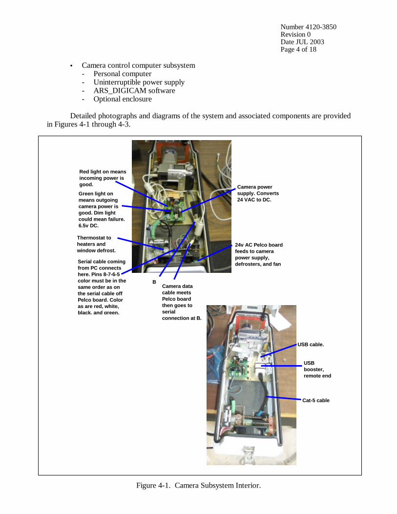
Number 4120-3850 Revision 0 Date JUL 2003 Page 4 of 18
• Camera control computer subsystem - Personal computer - Uninterruptible power supply - ARS_DIGICAM software - Optional enclosure
Detailed photographs and diagrams of the system and associated components are provided in Figures 4-1 through 4-3.
Figure 4-1. Camera Subsystem Interior.
Red light on means incoming power is good.
Green light on means outgoing camera power is good. Dim light could mean failure. 6.5v DC.
Thermostat to heaters and window defrost.
Serial cable coming from PC connects here. Pins 8-7-6-5 color must be in the same order as on the serial cable off Pelco board. Color as are red, white, black, and green.
B Camera data cable meets Pelco board then goes to serial connection at B.
Camera power supply. Converts 24 VAC to DC.
24v AC Pelco board feeds to camera power supply, defrosters, and fan
USB cable.
USB booster, remote end
Cat-5 cable
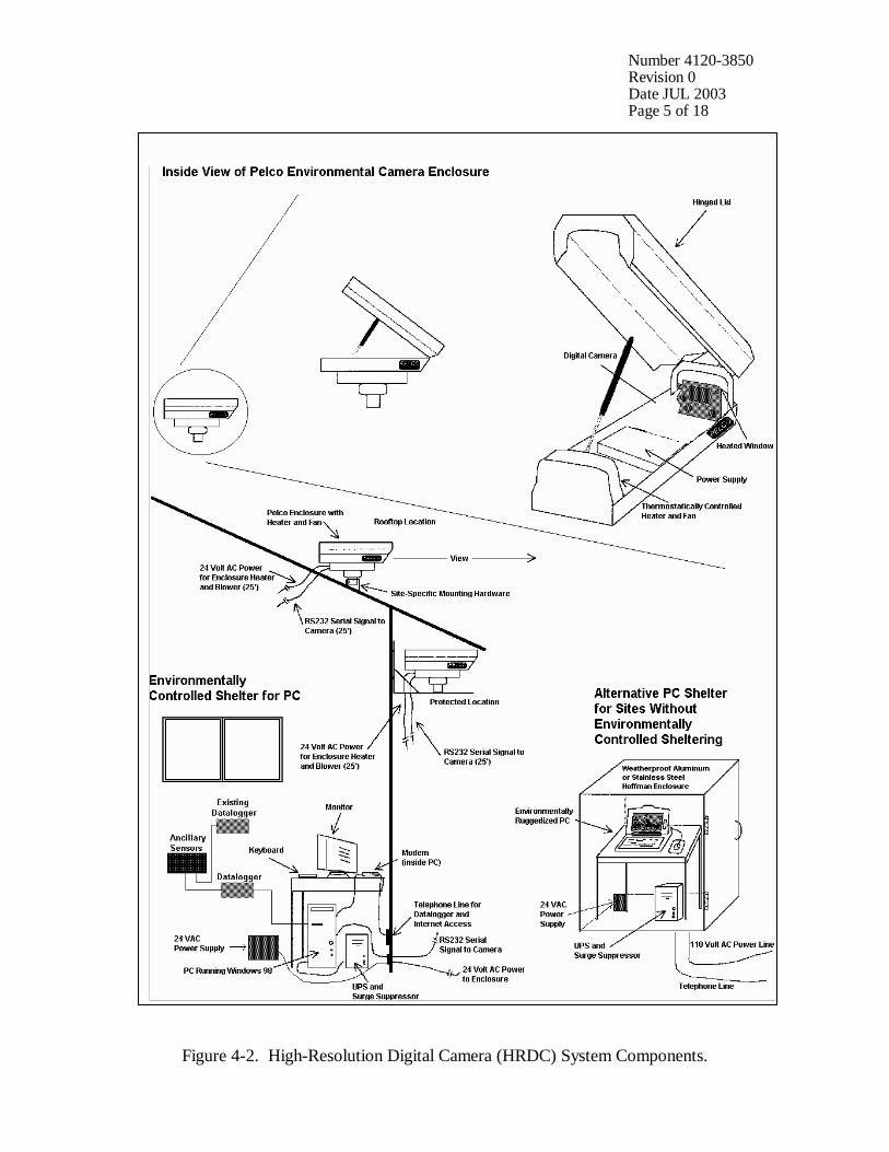
Number 4120-3850 Revision 0 Date JUL 2003 Page 5 of 18
Figure 4-2. High-Resolution Digital Camera (HRDC) System Components.
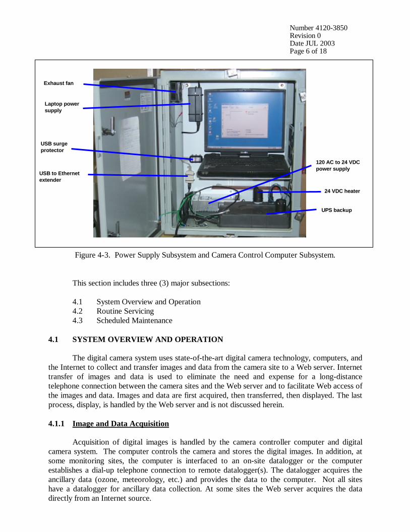
Number 4120-3850 Revision 0 Date JUL 2003 Page 6 of 18
Figure 4-3. Power Supply Subsystem and Camera Control Computer Subsystem. This section includes three (3) major subsections: 4.1 System Overview and Operation
4.2 Routine Servicing 4.3 Scheduled Maintenance 4.1 SYSTEM OVERVIEW AND OPERATION The digital camera system uses state-of-the-art digital camera technology, computers, and the Internet to collect and transfer images and data from the camera site to a Web server. Internet transfer of images and data is used to eliminate the need and expense for a long-distance telephone connection between the camera sites and the Web server and to facilitate Web access of the images and data. Images and data are first acquired, then transferred, then displayed. The last process, display, is handled by the Web server and is not discussed herein. 4.1.1 Image and Data Acquisition Acquisition of digital images is handled by the camera controller computer and digital camera system. The computer controls the camera and stores the digital images. In addition, at some monitoring sites, the computer is interfaced to an on-site datalogger or the computer establishes a dial-up telephone connection to remote datalogger(s). The datalogger acquires the ancillary data (ozone, meteorology, etc.) and provides the data to the computer. Not all sites have a datalogger for ancillary data collection. At some sites the Web server acquires the data directly from an Internet source.
24 VDC heater
UPS backup
120 AC to 24 VDC power supply
Exhaust fan
USB to Ethernet extender
USB surge protector
Laptop power supply
Number 4120-3850 Revision 0 Date JUL 2003 Page 7 of 18
The Web server updates the Web site when new data are uploaded from the camera sites. The timing of events associated with images and data acquisition is described below. It is assumed that the sites are configured for 15-minute intervals between acquisition episodes. The acquisition sequence is. Minutes after each 15-minute interval
Event
:00 :02 :06 :08 :12
Image is snapped and begins to download to camera controller computer Image download completed; ancillary data collection begins Ancillary data collection completes; image processing and data packaging begins Data processing completes; Internet upload of packaged data begins Upload completes
If the image acquisition, data acquisition, and upload process is not complete by :15, the process is aborted and attempted again at the next interval. Images that cannot be uploaded for any reason are stored on the camera controller computer and may be archived on CD-ROM as needed. 4.1.1.1 Image Acquisition Image acquisition from the digital camera is controlled by ARS_DIGICAM software installed on the camera controller computer. The cameras have large feature sets that allow most of the picture-taking flexibility found in film-based cameras, including:
• Flash control • Focus control (automatic or manual) • Exposure control • 3X optical zoom (Kodak) and 10X optical zoom (Olympus) • Image imprint with date and time
In addition, the digital cameras have several features not found with film-based cameras: • White balance control for different lighting types • Audio description of each image • Selectable image resolution and quality
The digital cameras are capable of acquiring high quality images at resolutions up to 1792
x 1200 pixels. While this resolution results in images too large for fast Web page display, it does allow for parts of the image to be used to digitally zoom into the image for close-up views of interesting scenes. Each image acquired is downloaded to the camera controller computer as a JPEG (Joint Photographic Experts Group) image using minimum compression (highest quality). The size of the image file depends on the detail in the image. A rural night shot will typically yield a file size less than 20 kilobytes while an urban night shot will typically yield a file size greater than 100 kilobytes. A high contrast daylight shot may yield a file size greater than 400 kilobytes.
Number 4120-3850 Revision 0 Date JUL 2003 Page 8 of 18
The camera communicates with the computer via a RS232 or USB serial connection. The ARS_DIGICAM software controls all aspects of camera operation, including configuring the camera, snapping the image, and downloading the image to the PC. The camera is on at all times, ready to accept commands from the computer. As noted above, the cameras are capable of operating using a variety of camera settings. For consistent results in the network, the settings must remain unchanged between images. All camera settings, as well as communication, file storage directories, Internet parameters, and datalogger information settings, are stored in a configuration file (ARS_DIGICAM.INI). The configuration file may be modified to suit the characteristics of the site. The camera controller computer controls the digital camera and instructs the camera when to snap a new image. The image is saved on the computer with a file name of ssssssjjjhhmm.JPG, where ssssss is the site name, jjj is the Julian date, and hhmm is the time. The image is moved into the appropriate daily archive .ZIP file named jjj_yyyy.ZIP, where jjj is the Julian date and yyyy is the year. The camera must be on to operate and have all pictures erased when first used. The camera has several capabilities that allow images to be taken under various conditions. The settings for these capabilities are set automatically by the software and include:
• Autofocus set to OFF • Focus set to INFINITY • Flash turned OFF • Image quality set to best available • Image size set to MAXIMUM • White balance set to DAYLIGHT
The only camera setting under user control is the zoom. Allowable zoom settings include: • Kodak DC260/DC265 = 37, 50, 62, 73, 85, 97, 111 • Kodak DC290 = any value from 38 to 115 • Olympus C-2100 and C-730 = any value from 38 to 380.
Zoom settings are in millimeters equivalent to a 35 mm camera. It takes approximately one
minute for the camera to snap and process a daytime image prior to download to the computer. The date and time associated with each image is local time. The computer will update its clock when changing between daylight-saving and standard time. In addition, the software will attempt to set the computer time to a high accuracy standard source while connected to the Internet during file transfer. 4.1.1.2 Data Acquisition The Web page displays ancillary data (if collected) to enhance the utility of the image. These ancillary data are available locally (alongside the camera system) or may be obtained from a remote site. If the data are available locally, a separate datalogger may be used to interface the sensors with the camera computer and keep the existing datalogger(s) unchanged and unaffected
Number 4120-3850 Revision 0 Date JUL 2003 Page 9 of 18
by the system’s components. The data are stored in the configuration file which is uploaded to the Internet along with the image and error files in the packaged data file. If the data are available via a remote datalogger, the computer can establish a dial-up telephone connection to the datalogger and acquire the data in much the same way as it would with a local datalogger. All configuration information related to data collection is included in the ARS_DIGICAM.INI configuration file. If ancillary data are available via an Internet (FTP or HTTP) source, these data are collected by the Web server instead of the camera PC. 4.1.1.3 File Structure
The disk drive and directory structure for the camera computer is as follows: C:\ARS_DIGICAM\ ARS_DIGICAM.EXE, ARS_DIGICAM.INI \Errors Daily error log files (*.err) \Data Images archived into daily .ZIP files (*.jpg, *.zip) \Data\Retry Images that failed FTP transfer (*.jpg, *.zip) \Data\Upload Images awaiting FTP transfer (*.jpg, *.zip) The \Retry directory will contain files that should have been uploaded but could not be. ARS_DIGICAM will attempt to upload the files at the time specified in the INI file.
The location of image and error files is defined in the ARS_DIGICAM.INI configuration file. An example file is presented as Figure 4-4.
4.1.2 Image and Data Transfer After being acquired and stored in the camera computer, images and data are packaged for transfer to the Web server via the Internet. 4.1.2.1 Data Packaging for Internet Transfer The image, ancillary air quality data, error files, and configuration files are packaged for transfer via FTP (File Transfer Protocol) to the Web server. Packaging includes:
• Compressing the image, data, error, and current configuration files into a PKZIP-compatible file.
• Applying a password to the zipped file to minimize upload of false images and/or data. • Storing the packaged file on the local disk.
The resulting packaged data consists of a single file ready for Internet transfer.
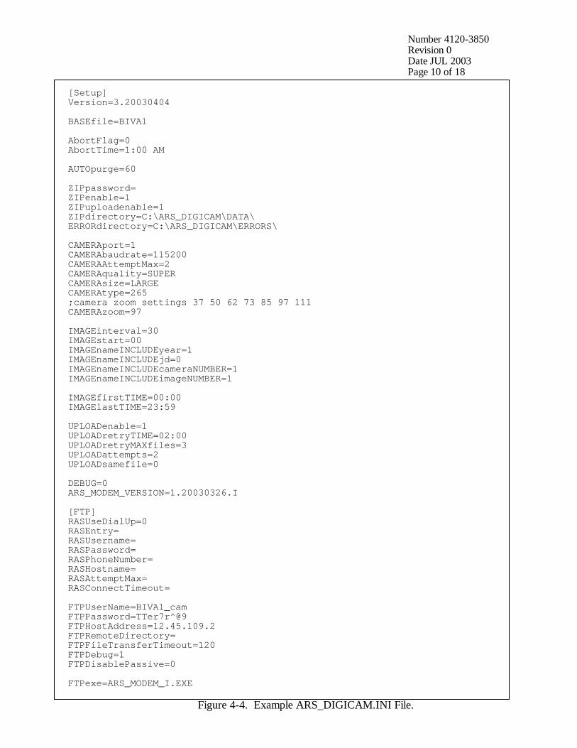
Number 4120-3850 Revision 0 Date JUL 2003 Page 10 of 18
[Setup] Version=3.20030404 BASEfile=BIVA1 AbortFlag=0 AbortTime=1:00 AM AUTOpurge=60 ZIPpassword= ZIPenable=1 ZIPuploadenable=1 ZIPdirectory=C:\ARS_DIGICAM\DATA\ ERRORdirectory=C:\ARS_DIGICAM\ERRORS\ CAMERAport=1 CAMERAbaudrate=115200 CAMERAAttemptMax=2 CAMERAquality=SUPER CAMERAsize=LARGE CAMERAtype=265 ;camera zoom settings 37 50 62 73 85 97 111 CAMERAzoom=97 IMAGEinterval=30 IMAGEstart=00 IMAGEnameINCLUDEyear=1 IMAGEnameINCLUDEjd=0 IMAGEnameINCLUDEcameraNUMBER=1 IMAGEnameINCLUDEimageNUMBER=1 IMAGEfirstTIME=00:00 IMAGElastTIME=23:59 UPLOADenable=1 UPLOADretryTIME=02:00 UPLOADretryMAXfiles=3 UPLOADattempts=2 UPLOADsamefile=0 DEBUG=0 ARS_MODEM_VERSION=1.20030326.I [FTP] RASUseDialUp=0 RASEntry= RASUsername= RASPassword= RASPhoneNumber= RASHostname= RASAttemptMax= RASConnectTimeout= FTPUserName=BIVA1_cam FTPPassword=TTer7r^@9 FTPHostAddress=12.45.109.2 FTPRemoteDirectory= FTPFileTransferTimeout=120 FTPDebug=1 FTPDisablePassive=0 FTPexe=ARS_MODEM_I.EXE
Figure 4-4. Example ARS_DIGICAM.INI File.
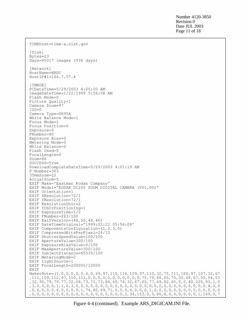
Number 4120-3850 Revision 0 Date JUL 2003 Page 11 of 18
TIMEhost=time-a.nist.gov [Disk] Bytes=23 Days=45017 images (938 days) [Network] HostName=HRDC HostIP#1=166.7.57.4 [IMAGE] PCDateTime=5/29/2003 4:00:00 AM ImageDateTime=1/22/1999 5:56:08 AM Flash Mode=0 Picture Quality=1 Camera Zoom=97 ISO=0 Camera Type=SR95A White Balance Mode=1 Focus Mode=1 Focus Position=0 Exposure=0 FNumber=80 Exposure Bias=0 Metering Mode=0 White Balance=0 Flash Used=0 FocalLength=0 Zoom=88 SUCCESS=True DownloadCompleteDateTime=5/29/2003 4:01:19 AM F-Number=303 35mmZoom=22 ActualZoom=5 EXIF Make="Eastman Kodak Company" EXIF Model="KODAK DC265 ZOOM DIGITAL CAMERA (V01.00)" EXIF Orientation=1 EXIF XResolution=72/1 EXIF YResolution=72/1 EXIF ResolutionUnit=2 EXIF YCbCrPositioning=1 EXIF ExposureTime=1/2 EXIF FNumber=283/100 EXIF ExifVersion=(48,50,48,48) EXIF DateTimeOriginal="1999:02:22 05:56:08" EXIF ComponentsConfiguration=(1,2,3,0) EXIF CompressedBitsPerPixel=24/10 EXIF ShutterSpeedValue=100/100 EXIF ApertureValue=300/100 EXIF ExposureBiasValue=0/100 EXIF MaxApertureValue=300/100 EXIF SubjectDistance=65535/100 EXIF MeteringMode=2 EXIF LightSource=1 EXIF FocalLength=208000/10000 EXIF MakerNote=(1,0,0,0,0,0,4,0,69,97,115,116,109,97,110,32,75,111,100,97,107,32,67,111,109,112,97,110,121,0,0,0,0,0,0,0,0,0,0,0,75,79,68,65,75,32,68,67,50,54,53,32,90,79,79,77,32,68,73,71,73,84,65,76,32,67,65,77,69,82,65,0,0,40,225,93,1,0,3,0,0,0,0,1,1,0,3,0,0,0,0,0,0,0,0,0,0,0,0,0,0,0,0,0,0,0,0,0,0,0,6,0,0,0,4,0,0,0,6,0,0,0,4,0,0,0,0,1,74,80,69,71,0,0,0,4,0,0,0,1,0,0,0,0,0,0,0,0,0,0,0,0,0,0,0,0,0,0,0,0,0,0,0,0,0,0,0,0,0,0,0,0,0,2,34,153,0,5,86,8,0,0,0,0,0,0,1,169,0,7
Figure 4-4 (continued). Example ARS_DIGICAM.INI File.
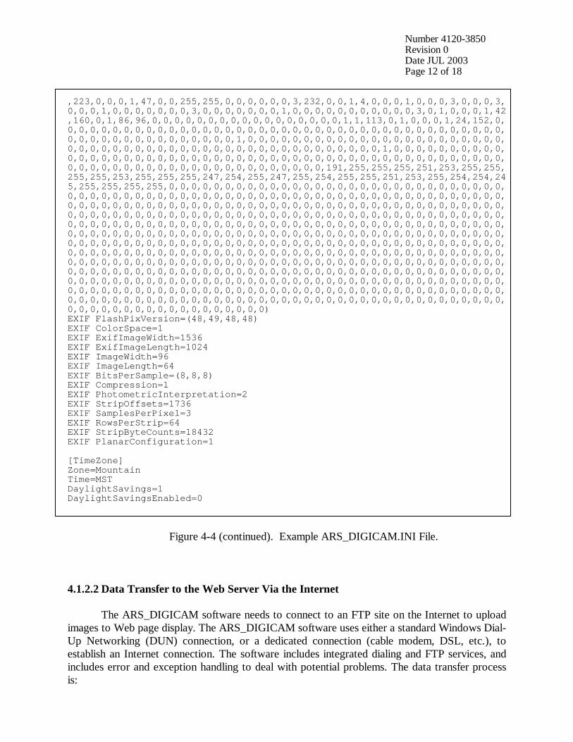
Number 4120-3850 Revision 0 Date JUL 2003 Page 12 of 18
,223,0,0,0,1,47,0,0,255,255,0,0,0,0,0,0,3,232,0,0,1,4,0,0,0,1,0,0,0,3,0,0,0,3, 0,0,0,1,0,0,0,0,0,0,0,3,0,0,0,0,0,0,0,1,0,0,0,0,0,0,0,0,0,0,0,3,0,1,0,0,0,1,42,160,0,1,86,96,0,0,0,0,0,0,0,0,0,0,0,0,0,0,0,0,0,1,1,113,0,1,0,0,0,1,24,152,0,0,0,0,0,0,0,0,0,0,0,0,0,0,0,0,0,0,0,0,0,0,0,0,0,0,0,0,0,0,0,0,0,0,0,0,0,0,0,0,0,0,0,0,0,0,0,0,0,0,0,0,0,0,0,1,0,0,0,0,0,0,0,0,0,0,0,0,0,0,0,0,0,0,0,0,0,0,0,0,0,0,0,0,0,0,0,0,0,0,0,0,0,0,0,0,0,0,0,0,0,0,0,0,0,0,0,1,0,0,0,0,0,0,0,0,0,0,0,0,0,0,0,0,0,0,0,0,0,0,0,0,0,0,0,0,0,0,0,0,0,0,0,0,0,0,0,0,0,0,0,0,0,0,0,0,0,0,0,0,0,0,0,0,0,0,0,0,0,0,0,0,0,0,0,0,0,0,0,0,191,255,255,255,251,253,255,255,255,255,253,255,255,255,247,254,255,247,255,254,255,255,251,253,255,254,254,245,255,255,255,255,0,0,0,0,0,0,0,0,0,0,0,0,0,0,0,0,0,0,0,0,0,0,0,0,0,0,0,0,0,0,0,0,0,0,0,0,0,0,0,0,0,0,0,0,0,0,0,0,0,0,0,0,0,0,0,0,0,0,0,0,0,0,0,0,0,0,0,0,0,0,0,0,0,0,0,0,0,0,0,0,0,0,0,0,0,0,0,0,0,0,0,0,0,0,0,0,0,0,0,0,0,0,0,0,0,0,0,0,0,0,0,0,0,0,0,0,0,0,0,0,0,0,0,0,0,0,0,0,0,0,0,0,0,0,0,0,0,0,0,0,0,0,0,0,0,0,0,0,0,0,0,0,0,0,0,0,0,0,0,0,0,0,0,0,0,0,0,0,0,0,0,0,0,0,0,0,0,0,0,0,0,0,0,0,0,0,0,0,0,0,0,0,0,0,0,0,0,0,0,0,0,0,0,0,0,0,0,0,0,0,0,0,0,0,0,0,0,0,0,0,0,0,0,0,0,0,0,0,0,0,0,0,0,0,0,0,0,0,0,0,0,0,0,0,0,0,0,0,0,0,0,0,0,0,0,0,0,0,0,0,0,0,0,0,0,0,0,0,0,0,0,0,0,0,0,0,0,0,0,0,0,0,0,0,0,0,0,0,0,0,0,0,0,0,0,0,0,0,0,0,0,0,0,0,0,0,0,0,0,0,0,0,0,0,0,0,0,0,0,0,0,0,0,0,0,0,0,0,0,0,0,0,0,0,0,0,0,0,0,0,0,0,0,0,0,0,0,0,0,0,0,0,0,0,0,0,0,0,0,0,0,0,0,0,0,0,0,0,0,0,0,0,0,0,0,0,0,0,0,0,0,0,0,0,0,0,0,0,0,0,0,0,0,0,0,0,0,0,0,0,0,0,0,0,0,0,0,0,0,0,0,0,0,0,0,0,0,0,0,0,0,0,0,0,0,0,0,0,0,0,0,0,0,0,0,0,0,0,0,0,0,0,0,0,0,0,0,0,0,0,0,0,0,0,0,0,0,0,0,0,0,0,0,0,0,0,0,0,0,0,0,0,0,0,0,0,0,0,0,0,0,0,0,0,0,0,0,0,0,0,0,0,0,0,0,0,0,0,0,0,0,0,0,0,0,0,0,0,0,0,0,0,0,0,0,0) EXIF FlashPixVersion=(48,49,48,48) EXIF ColorSpace=1 EXIF ExifImageWidth=1536 EXIF ExifImageLength=1024 EXIF ImageWidth=96 EXIF ImageLength=64 EXIF BitsPerSample=(8,8,8) EXIF Compression=1 EXIF PhotometricInterpretation=2 EXIF StripOffsets=1736 EXIF SamplesPerPixel=3 EXIF RowsPerStrip=64 EXIF StripByteCounts=18432 EXIF PlanarConfiguration=1 [TimeZone] Zone=Mountain Time=MST DaylightSavings=1 DaylightSavingsEnabled=0
Figure 4-4 (continued). Example ARS_DIGICAM.INI File.
4.1.2.2 Data Transfer to the Web Server Via the Internet The ARS_DIGICAM software needs to connect to an FTP site on the Internet to upload images to Web page display. The ARS_DIGICAM software uses either a standard Windows Dial-Up Networking (DUN) connection, or a dedicated connection (cable modem, DSL, etc.), to establish an Internet connection. The software includes integrated dialing and FTP services, and includes error and exception handling to deal with potential problems. The data transfer process is:
Number 4120-3850 Revision 0 Date JUL 2003 Page 13 of 18
• An Internet connection is established using Dial-Up Networking, or a dedicated connection is verified.
• An FTP connection to the Web server is opened. • The packaged data file described above is transferred to the Web server. • The FTP connection is closed. • The Dial-Up Networking connection is closed.
The Internet transfer will be attempted several times and timeout settings assure the
transfer ends during the current interval. Packaged data are saved to the camera site PC’s hard disk and can be archived to CD-ROM as necessary. It is important to have the correct dial-up networking connection settings; the connection should be tested using a browser or other Internet client software prior to use with the camera software. The disconnect idle time setting should be 2 minutes and the wait for dialtone setting should be set. It takes approximately two minutes to complete an FTP upload of the data. The operational log displayed by the ARS_DIGICAM software provides information on the operation of the data acquisition and transfer. All information displayed is saved in the daily error (.ERR) file for troubleshooting purposes. The operational log is very useful in tracking data connection activities and resolving transfer problems. 4.1.3 ARS_DIGICAM Software Each high-resolution digital camera system includes a desktop or laptop PC running Microsoft Windows as its operating system and ARS_DIGICAM software for camera operation. The ARS_DIGICAM software performs the following tasks:
• Controls the digital camera • Acquires JPG images from the digital camera • Packages JPG images and associated image information into ZIP files • Establishes a dial-up connection to the Internet • Establishes a connection to an FTP site on the Internet • Transfers the JPG or ZIP files to the FTP site • Accepts data from onsite dataloggers for inclusion with the image upload
ARS_DIGICAM software features include: • The ability to interface with on-site and remote (via modem) dataloggers • User-selectable image and data acquisition intervals • Standard Windows interface
The ARS_DIGICAM software consists of several tabbed panes of information. In the
standard configuration, the following tabs are available:
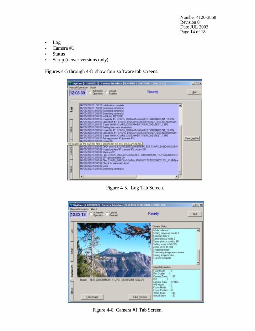
Number 4120-3850 Revision 0 Date JUL 2003 Page 14 of 18
• Log • Camera #1 • Status • Setup (newer versions only) Figures 4-5 through 4-8 show four software tab screens.
Figure 4-5. Log Tab Screen.
Figure 4-6. Camera #1 Tab Screen.
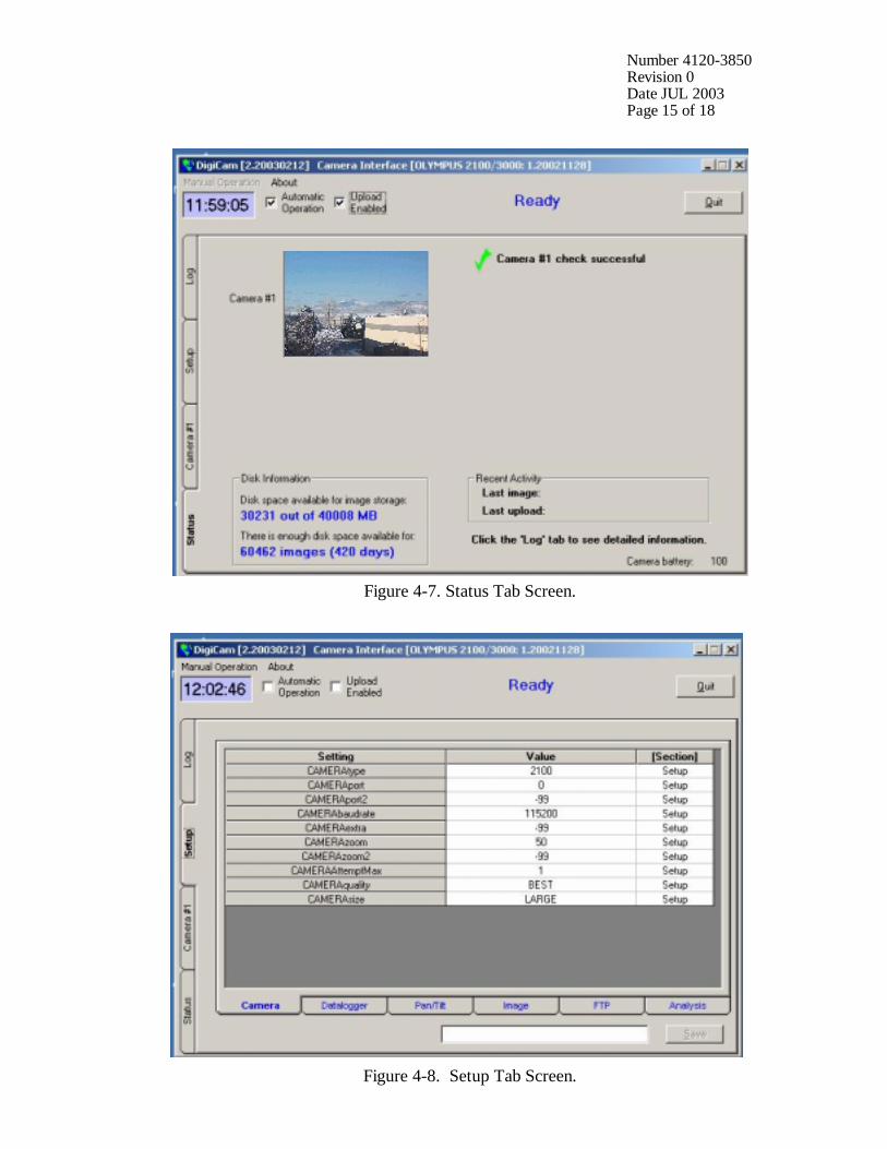
Number 4120-3850 Revision 0 Date JUL 2003 Page 15 of 18
Figure 4-7. Status Tab Screen.
Figure 4-8. Setup Tab Screen.
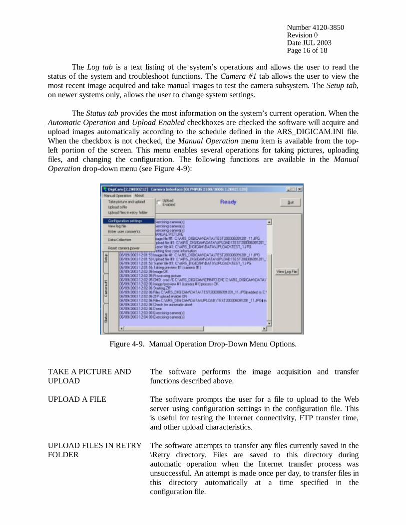
Number 4120-3850 Revision 0 Date JUL 2003 Page 16 of 18
The Log tab is a text listing of the system’s operations and allows the user to read the status of the system and troubleshoot functions. The Camera #1 tab allows the user to view the most recent image acquired and take manual images to test the camera subsystem. The Setup tab, on newer systems only, allows the user to change system settings. The Status tab provides the most information on the system’s current operation. When the Automatic Operation and Upload Enabled checkboxes are checked the software will acquire and upload images automatically according to the schedule defined in the ARS_DIGICAM.INI file. When the checkbox is not checked, the Manual Operation menu item is available from the top-left portion of the screen. This menu enables several operations for taking pictures, uploading files, and changing the configuration. The following functions are available in the Manual Operation drop-down menu (see Figure 4-9):
Figure 4-9. Manual Operation Drop-Down Menu Options.
TAKE A PICTURE AND UPLOAD
The software performs the image acquisition and transfer functions described above.
UPLOAD A FILE The software prompts the user for a file to upload to the Web server using configuration settings in the configuration file. This is useful for testing the Internet connectivity, FTP transfer time, and other upload characteristics.
UPLOAD FILES IN RETRY FOLDER
The software attempts to transfer any files currently saved in the \Retry directory. Files are saved to this directory during automatic operation when the Internet transfer process was unsuccessful. An attempt is made once per day, to transfer files in this directory automatically at a time specified in the configuration file.
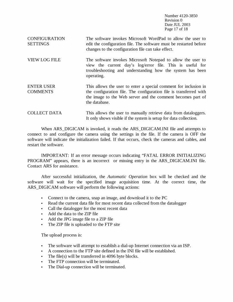
Number 4120-3850 Revision 0 Date JUL 2003 Page 17 of 18
CONFIGURATION SETTINGS
The software invokes Microsoft WordPad to allow the user to edit the configuration file. The software must be restarted before changes to the configuration file can take effect.
VIEW LOG FILE The software invokes Microsoft Notepad to allow the user to view the current day’s log/error file. This is useful for troubleshooting and understanding how the system has been operating.
ENTER USER COMMENTS
This allows the user to enter a special comment for inclusion in the configuration file. The configuration file is transferred with the image to the Web server and the comment becomes part of the database.
COLLECT DATA This allows the user to manually retrieve data from dataloggers. It only shows visible if the system is setup for data collection.
When ARS_DIGICAM is invoked, it reads the ARS_DIGICAM.INI file and attempts to connect to and configure the camera using the settings in the file. If the camera is OFF the software will indicate the initialization failed. If that occurs, check the cameras and cables, and restart the software. IMPORTANT: If an error message occurs indicating “FATAL ERROR INITIALIZING PROGRAM” appears, there is an incorrect or missing entry in the ARS_DIGICAM.INI file. Contact ARS for assistance. After successful initialization, the Automatic Operation box will be checked and the software will wait for the specified image acquisition time. At the correct time, the ARS_DIGICAM software will perform the following actions:
• Connect to the camera, snap an image, and download it to the PC • Read the current data file for most recent data collected from the datalogger • Call the datalogger for the most recent data • Add the data to the ZIP file • Add the JPG image file to a ZIP file • The ZIP file is uploaded to the FTP site
The upload process is: • The software will attempt to establish a dial-up Internet connection via an ISP. • A connection to the FTP site defined in the INI file will be established. • The file(s) will be transferred in 4096 byte blocks. • The FTP connection will be terminated. • The Dial-up connection will be terminated.
Number 4120-3850 Revision 0 Date JUL 2003 Page 18 of 18
4.2 ROUTINE SERVICING 4.2.1 Daily Procedures Daily procedures are performed to verify the camera system is working correctly. These procedures are listed below. VERIFY DATA Verify that the data displayed by the ARS_DIGICAM software
match the data on the external instrumentation (via the datalogger).
VERIFY IMAGE Verify the current image displayed on the computer monitor is the correct view and zoom.
CHECK LOG Check the operational log displayed by the ARS_DIGICAM software for significant error messages.
CLEAN WINDOW Clean the window in front of the camera. Refer to TI 4120-3950, Troubleshooting and Emergency Maintenance Procedures for the High-Resolution Digital Camera System (HRDC) for help with operational problems. If the computer shows the system to be non-functional, it may be necessary to exit and restart the ARS_DIGICAM software, or to re-boot the computer and start the software. Refer to the TI 4120-3950 for more information. 4.2.2 Monthly Procedures Data management is handled monthly. If the hard drive is nearly full, the software will fail when attempting to manage the image files. On a monthly basis the disk on the camera computer must be checked to verify sufficient space is available for another month of data. If sufficient space is not available, it is necessary to archive, then delete files from the data directory. The purpose of the archive is to assure the images taken by the camera are moved to safe storage, and to make room on the computer for future images. These CDs and the Web server archives represent the only image archive. Refer to TI 4610-5040, Digital Camera Image and Data Archives for archive procedures. 4.3 SCHEDULED MAINTENANCE Long-term and scheduled maintenance requirements of digital camera systems are unknown at this time and will become clear as operational experience builds. All scheduled maintenance requested by the data coordinator or performed by the site operator must be thoroughly documented on the site-specific Quality Assurance Database. The site operator may be asked to replace specific components of the system in the event of failure. Problems and equipment malfunctions requiring extensive troubleshooting and/or maintenance are fully described in TI 4120-3950, Troubleshooting and Emergency Maintenance Procedures for the High-Resolution Digital Camera System (HRDC).