
August 17, 2000
54
Geotechnical Investigation South Cooper Mountain Development SW 175th Avenue and SW Goldcrest Lane Beaverton, Oregon January 14, 2021 (ISSUED 2/16/2021) Prepared for Ben Sturtz BRIDGE Housing 38 NW Davis Street, #450 Portland, OR 97209 Prepared by 9750 SW Nimbus Avenue Beaverton, OR 97008-7172 (503) 641-3478 | www.gri.com EXHIBIT 3.5
Transcript of August 17, 2000

Geotechnical Investigation South Cooper Mountain
Development SW 175th Avenue and SW Goldcrest Lane
Beaverton, Oregon
January 14, 2021 (ISSUED 2/16/2021)
Prepared for
Ben Sturtz BRIDGE Housing
38 NW Davis Street, #450 Portland, OR 97209
Prepared by
9750 SW Nimbus Avenue Beaverton, OR 97008-7172
(503) 641-3478 | www.gri.com
EXHIBIT 3.5
cruiz
Text Box
Received Planning Division
cruiz
Date

GRI PN #6436-B – South Cooper Mountain Development January 14, 2021 (ISSUED 2/16/2021)
TABLE OF CONTENTS 1 INTRODUCTION................................................................................................................. 1
2 BACKGROUND INFORMATION ........................................................................................ 1
3 SITE DESCRIPTION ............................................................................................................ 1
3.1 General ................................................................................................................................................................. 1
3.2 Geology ................................................................................................................................................................ 1
4 PROJECT DESCRIPTION .................................................................................................... 2
5 SUBSURFACE CONDITIONS .............................................................................................. 2
5.1 General ................................................................................................................................................................. 2
5.2 Sampling .............................................................................................................................................................. 2
5.3 Soils ....................................................................................................................................................................... 3
5.4 Groundwater ...................................................................................................................................................... 5
6 CONCLUSIONS AND RECOMMENDATIONS ................................................................... 5
6.1 General ................................................................................................................................................................. 5
6.2 Seismic Considerations .................................................................................................................................. 6
6.3 Earthwork ............................................................................................................................................................ 8
6.4 Excavation ........................................................................................................................................................... 9
6.5 Structural Fill .................................................................................................................................................... 12
6.6 Foundation Support ...................................................................................................................................... 14
6.7 Subdrainage/Floor Support ....................................................................................................................... 15
6.8 Retaining/Embedded Walls ........................................................................................................................ 16
6.9 Pavement Design ........................................................................................................................................... 18
7 DESIGN REVIEW AND CONSTRUCTION SERVICES....................................................... 19
8 LIMITATIONS ................................................................................................................... 19
9 REFERENCES ..................................................................................................................... 21
TABLES Table 5-1: Groundwater Depth Measurements .......................................................................................... 5 Table 6-1: Recommended Seismic Design Parameters (2019 OSSC/ASCE 7-16) .......................... 7 Table 6-2: Recommended Pavement Sections .......................................................................................... 18 APPENDICES Appendix A: Field Explorations and Laboratory Testing

GRI PN #6436-B – South Cooper Mountain Development January 14, 2021 (ISSUED 2/16/2021)
FIGURES Figure 1: Vicinity Map Figure 2: Site Plan Figure 3: Subdrainage Detail Figure 4: Surcharge-Induced Lateral Pressure

GRI PN #6436-B – South Cooper Mountain Development Page 1 January 14, 2021 (ISSUED 2/16/2021)
1 INTRODUCTION As requested, GRI completed a geotechnical investigation for the proposed South Cooper Mountain development located on the southeastern corner of the intersection of SW 175th Avenue and SW Goldcrest Lane in Beaverton, Oregon. The Vicinity Map, Figure 1, shows the general location of the site. The purpose of this investigation was to evaluate subsurface conditions at the site and develop geotechnical recommendations for use in the design and construction of future development. The investigation included a review of existing geotechnical information for the site and surrounding area, subsurface explorations, laboratory testing, and engineering analyses. This report describes the work accomplished and provides conclusions and recommendations for use in the design and construction of the new development.
2 BACKGROUND INFORMATION As you know, GRI completed a geotechnical investigation for the South Cooper Mountain Heights multifamily housing development that borders the southern side of the project site in October 2018. In addition, Hardman Geotechnical Services, Inc. (HGSI), completed a geotechnical engineering evaluation in August 2018 of the existing fill soils that mantle the site. The following reports were reviewed, from which relevant information was used for this investigation.
“Geotechnical Engineering Evaluation of Imported Fill, South Cooper Mountain Multi-Family, Beaverton, Oregon,” dated August 2, 2018, prepared by HGSI for West Hills Land Development.
“Geotechnical Investigation, South Cooper Mountain Heights Multifamily Development, SW Scholls Ferry Road and SW 175th Avenue, Beaverton, Oregon,” dated October 22, 2018, prepared by GRI for The Spanos Corporation.
3 SITE DESCRIPTION 3.1 General
The proposed development will be located across the street from Mountainside High School and bordered by SW Goldcrest Lane on the north, SW 172nd Terrace on the east, the South Cooper Mountain Heights development on the south, and SW 175th Avenue on the west. The site is currently covered with gravel and is being used as a construction staging area. Review of available satellite imagery indicates the ground surface slopes downward from north to south across the site with about 20 feet of elevation difference.
3.2 Geology Subsurface explorations completed on site by GRI indicate the site is mantled with up to 7.5 feet of silt and clay fill soils. Published geologic mapping indicates the fill soils are underlain by residual soils produced from the weathering of the underlying Columbia River

GRI PN #6436-B – South Cooper Mountain Development Page 2 January 14, 2021 (ISSUED 2/16/2021)
Basalt (Madin, 2004). These residual soils typically consist of stiff to very stiff silt and clay soils with varying amounts of coarse-grained sand to gravel-sized fragments of decomposed basalt. With increased depth, the residual soil becomes more granular and progressively transitions to weathered basalt.
4 PROJECT DESCRIPTION We understand the project will consist of constructing a four-story, multifamily housing building. Information provided by you indicates the new building will have maximum column and wall loads on the order of 150 kips and 5 kips/foot, respectively. We understand the project will be designed and constructed in accordance with the 2019 Oregon Structural Specialty Code (OSSC). Grading information has not been provided; however, based on the existing site topography, we anticipate the northern portion of the building may be partially embedded into the existing slope and the southern portion may be supported on a retaining structure.
5 SUBSURFACE CONDITIONS 5.1 General
As part of our 2018 geotechnical investigation for the South Cooper Mountain Heights Multifamily Development projects, subsurface materials and conditions at the site were investigated with two borings, designated B-1 and B-2, and one cone penetration test (CPT) probe, designated CPT-1. For this investigation, GRI completed four additional borings, designated B-3 through B-6; four dilatometer test (DMT) soundings, designated DMT-1 through DMT-4, and four Wildcat dynamic cone penetration test (DCPT) probes, designated DCPT-1 through DCPT-4, between December 17 and 18, 2020. The borings were advanced to depths of about 11 feet to 30 feet, the CPT probe to a depth of about 35 feet, the DMT probes to depths of about 11.2 feet to 29.5 feet, and the DCPT probes to depths of about 5.1 feet to 12.6 feet below the existing site grades. The approximate locations of the explorations completed for this investigation are shown on Figure 2. Logs of the explorations are provided on Figures 1A through 12A. The field and laboratory programs conducted to evaluate the physical engineering properties of the materials encountered in the explorations are described in Appendix A. The terms and symbols used to describe the materials encountered in the explorations are defined in Tables 1A through 4A and the attached legend.
5.2 Sampling Disturbed and undisturbed soil samples were obtained from the borings at 2.5- to 5-foot intervals of depth. Disturbed soil samples were obtained using a 2-inch-outside-diameter standard split-spoon sampler or a 1.25-inch-outside-diameter direct-push probe plastic sleeve. Standard penetration tests (SPTs) were conducted in borings B-1 and B-2 by driving the split-spoon sampler into the soil a distance of 18 inches using a 140-pound hammer

GRI PN #6436-B – South Cooper Mountain Development Page 3 January 14, 2021 (ISSUED 2/16/2021)
dropped 30 inches. The number of blows required to drive the sampler the last 12 inches is known as the Standard Penetration Resistance, or SPT N-value. SPT N-values provide a measure of the relative density of granular soils and the relative consistency of cohesive soils. Relatively undisturbed soil samples were collected by pushing a 3-inch-outside-diameter Shelby tube into the undisturbed soil a maximum of 24 inches using the hydraulic ram of the drill rig.
5.3 Soils For the purpose of discussion, the materials encountered in the explorations have been grouped into the following categories:
a. SURFACING b. FILL c. Clayey SILT to Silty CLAY (Residual Soil) d. Sandy SILT to Silty SAND (Decomposed Basalt) e. BASALT (Columbia River Basalt)
The following paragraphs provide a description of the materials encountered and a discussion of the groundwater conditions at the site.
a. SURFACING Explorations B-3, B-4, B-6, DMT-1 through DMT-4, and DCPT-1 through DCPT-4 were advanced in areas surfaced with about 6 inches to 24 inches of crushed rock.
b. FILL Clayey silt to silty clay fill was encountered at the ground surface in explorations B-1, B-5, and CPT-1 and beneath surfacing in explorations B-4, B-6, DMT-2, and DMT-3. The fill extends to depths of about 5 feet to 7.5 feet and consists of brown to dark brown clayey silt to silty clay containing a trace of fine-grained sand. Scattered crushed rock was encountered in the fill in the upper 12 inches of boring B-5. The relative consistency of the fill is medium stiff to very stiff based on SPT N-values, CPT tip-resistance values, DMT constrained modulus values, and DCPT blow counts. The moisture content of the fill soils generally ranges from 4% to 30%. Atterberg-limits test results indicate the fill has a liquid limit of 53% and plasticity index of 28%, see Figure 13A.
c. Clayey SILT to Silty CLAY (Residual Soil) Residual soil consisting of clayey silt to silty clay was encountered at the ground surface in boring B-2, beneath surfacing in explorations B-3, DMT-1, DMT-4, and DCPT-1 through DCPT-4, and beneath fill in explorations B-1, B-4 through B-6, DMT-2, DMT-3, and CPT-1. The residual soil extends to depths of about 6.5 feet to 23 feet below the ground surface. In general, the residual soil is brown and grades to red-brown with increased depth and
GRI PN #6436-B – South Cooper Mountain Development Page 4 January 14, 2021 (ISSUED 2/16/2021)
contains a trace of fine- to coarse-grained sand. The relative consistency of the residual soil is medium stiff to very stiff based on SPT N-values, CPT tip-resistance values, DMT constrained-modulus values, DCPT blow counts, and Torvane shear-strength measurements. The natural moisture content of the residual soil ranges from about 9% to 61%. Atterberg-limits test results indicate the residual soil has a liquid limit of 56% and plasticity index of 35%, see Figure 13A.
A consolidation test was conducted on a sample of residual soil obtained at a depth of about 5.8 feet in boring B-1. Test results indicate the soil is overconsolidated and has a very low compressibility in the preconsolidated range of stresses and a moderate compressibility in the normally consolidated range of stresses, see Figure 14A.
Boring B-2 was terminated in residual soil at a depth of about 11 feet.
d. Sandy SILT to Silty SAND (Decomposed Basalt) Decomposed basalt consisting of sandy silt to silty sand was encountered beneath clayey silt to silty clay (residual soil) in all the explorations except B-2 and B-3 and extends to depths of about 5 feet to 29 feet below the ground surface. In general, the decomposed basalt brown, dark brown, dark gray, or red-brown with varying degrees of gray, black, or orange mottling, and consists of fine- to coarse-grained silty sand to sandy silt containing up to a trace of clay and gravel-sized fragments of decomposed basalt. Relict rock structure was present throughout the unit. Our experience in the immediate site vicinity indicates this deposit usually contains abundant cobbles and scattered boulders of decomposed basalt, and zones of less-weathered basalt. Based on SPT N-values, CPT tip-resistance values, DMT constrained-modulus values, and DCPT blow counts, the relative consistency of the sandy silt is stiff to hard and the relative density of the silty sand is medium dense to very dense. The natural moisture content of the decomposed basalt ranges from about 18% to 56%.
Explorations B-4 through B-5, DMT-1 through DMT-4, and DCPT-1 through DCPT-4 were terminated in decomposed basalt at depths of about 5.1 feet to 30 feet.
e. BASALT (Columbia River Basalt) Extremely soft (R0) to very soft (R1), gray basalt of the Columbia River Basalt Group was encountered beneath sandy silt to silty sand (decomposed basalt) in explorations B-1, B-6, and CPT-1 at depths of about 25 feet, 15 feet, and 34.5 feet, respectively. SPT N-values of 50 blows for 5.5 inches of sampler penetration (practical refusal is defined as 50 blows for less than 6 inches of sampler penetration) were recorded in the basalt. Although highly variable, we anticipate the weathering of the basalt decreases with depth and the relative hardness increases. Explorations B-1, B-6, and CPT-1 were terminated in basalt at depths of about 29.5 feet, 18.5 feet, and 35 feet, respectively.

GRI PN #6436-B – South Cooper Mountain Development Page 5 January 14, 2021 (ISSUED 2/16/2021)
5.4 Groundwater Groundwater was encountered in all the borings except for B-2 at the time of drilling. Table 5-1 summarizes the groundwater depth measurements recorded following completion of the boreholes and the date of the measurement.
Table 5-1: GROUNDWATER DEPTH MEASUREMENTS
Date Boring Depth, ft 6/27/2018 B-1 15.8
6/27/2018 B-2 Not Encountered
12/17/2020 B-3 11.0
12/17/2020 B-4 10.5
12/17/2020 B-5 10.0
12/17/2020 B-6 11.0
We anticipate the local groundwater level typically occurs at depths of about 10 feet to 15 feet below the ground surface throughout the year; however, perched groundwater may approach the ground surface during the wet winter and spring months or following periods of heavy or prolonged precipitation.
6 CONCLUSIONS AND RECOMMENDATIONS 6.1 General
Subsurface explorations completed for this investigation indicate the southern portion of the site is mantled with about 5 feet to 7.5 feet of medium-stiff to very stiff clayey silt to silty clay fill soils. Our review of the HGSI report and the results of our subsurface explorations indicate the fill was placed and compacted in a controlled manner as structural fill. The fill is underlain by medium-stiff to very stiff clayey silt to silty clay residual soils that also mantle the ground surface in the northern portion of the site. With increased depth, the residual soil becomes more granular and transitions to decomposed basalt. We anticipate the local groundwater level typically occurs at depths of about 10 feet to 15 feet below the ground surface throughout the year; however, localized perched-groundwater conditions may develop at shallower depths during the wet winter and spring months or following periods of heavy or prolonged precipitation.
In our opinion, foundation support for new structural loads can be provided by conventional spread and wall foundations established in firm, undisturbed soil or compacted structural fill. The primary geotechnical considerations associated with development of the site include previous site development, the presence of fine-grained soils at the ground surface that are extremely moisture sensitive, the potential for shallow perched-groundwater conditions, and the presence of shallow basalt. The following

GRI PN #6436-B – South Cooper Mountain Development Page 6 January 14, 2021 (ISSUED 2/16/2021)
sections of this report provide our conclusions and recommendations for use in the design and construction of the project.
6.2 Seismic Considerations
6.2.1 General We understand the project will be designed in accordance with 2019 OSSC, which references the American Society of Civil Engineers (ASCE) 7-16 document, Minimum Design Loads for Buildings and Other Structures (ASCE 7-16), for seismic design.
6.2.2 Code Background The ASCE 7-16 seismic-hazard levels are based on a Risk-Targeted Maximum Considered Earthquake (MCER) with the intent of including the probability of structural collapse. Based on generalized building fragility curves, seismic design of a structure using the probabilistic MCER represents a targeted risk level of 1% in 50 years probability of collapse in the direction of maximum horizontal response. In general, these risk-targeted ground motions are developed by applying adjustment factors of directivity and risk coefficients to the 2% probability of exceedance in 50 years (2,475-year return-period hazard level) ground motions developed from the recently updated 2014 U.S. Geological Survey (USGS) probabilistic seismic-hazard maps. The risk-targeted probabilistic values are also subject to a deterministic check, which is computed from the models of earthquake sources and ground-motion propagation that form the basis of the 2014 USGS National Seismic Hazard Maps (NSHMs). ASCE 7-16 defines the site-specific deterministic MCER ground motions in terms of 84th-percentile, 5%-damped response spectral acceleration in the direction of maximum horizontal response. The MCER ground motions are taken as the lesser of the probabilistic and deterministic spectral accelerations.
6.2.3 Site Response The ASCE methodology uses two bedrock spectral response parameters, SS and S1, corresponding to periods around 0.2 second and 1.0 second to develop the MCER response spectrum. To establish the ground-surface MCER spectrum, these bedrock spectral parameters are adjusted for site class using the short- and long-period site coefficients, Fa and Fv, in accordance with Section 11.4.3 of ASCE 7-16, which includes new seismic site coefficients to adjust the mapped values for soil properties.
The SS and S1 parameters for the site located at the approximate latitude and longitude coordinates of 45.4295° N latitude and 122.8548° W longitude are 0.85 g and 0.40 g, respectively, for Site Class B, or bedrock conditions.
In our opinion, based on the results of our subsurface explorations, the site is classified as Site Class D, or a very dense soil and soft rock site, in accordance with Chapter 20 of ASCE

GRI PN #6436-B – South Cooper Mountain Development Page 7 January 14, 2021 (ISSUED 2/16/2021)
7-16. Site coefficients Fa and Fv of 1.16 and 1.90, respectively, were used to develop the Site Class D MCER-level spectrum in accordance with Section 11.4 of ASCE 7-16. However, Section 11.4.8 of ASCE 7-16 requires a ground-motion hazard analysis be completed for structures on Site Class D sites to determine the Fv coefficient when the S1 parameter is greater than or equal to 0.2 g. The code provides an exception that waives the ground-motion hazard analysis if the seismic-response coefficient, Cs, is determined in accordance with Section 11.4.8, Exception 2, of ASCE 7-16. We anticipate the response coefficient will be developed as discussed above; therefore, the code-based, Site Class D, ground-surface, MCER response spectrum is appropriate for design of the structures. The design-level response spectrum is calculated as two thirds of the ground-surface MCER spectrum.
The recommended MCER- and design-level spectral response parameters for Site Class D conditions are tabulated below in Table 6-1 and were developed assuming Cs will be determined in accordance with Section 11.4.8, Exception 2, of ASCE 7-16.
Table 6-1: RECOMMENDED SEISMIC DESIGN PARAMETERS (2019 OSSC/ASCE 7-16)
Seismic Parameter Recommended Value*
Site Class D
MCER 0.2-Sec Period Spectral Response Acceleration, SMS
0.99 g
MCER 1.0-Sec Period Spectral Response Acceleration, SM1
0.76 g
Design-Level 0.2-Sec Period Spectral Response Acceleration, SDS
0.66 g
Design-Level 1.0-Sec Period Spectral Response Acceleration, SD1
0.51 g
*Should be reviewed based on structural requirements in accordance with Sections 11.4.8 and 12.8 of ASCE 7-16.
6.2.4 Liquefaction and Other Seismic Hazards Based on the relative density of the granular soils and stress history, shear-strength characteristics, and plasticity of the fine-grained soils below the groundwater level, it is our opinion the risk of liquefaction and/or significant cyclic softening is generally low during a code-based seismic event. The risk of damage by tsunami and/or seiche at the site is absent. The site is less than about 5.2 kilometers from the assumed locations of the Canby-Molalla Fault and Beaverton Fault Zone (USGS, 2008). Unless occurring on a previously unmapped or unknown fault, it is our opinion the risk of ground rupture at the site is low.

GRI PN #6436-B – South Cooper Mountain Development Page 8 January 14, 2021 (ISSUED 2/16/2021)
6.3 Earthwork
6.3.1 General The fine-grained soils that mantle the site are moisture sensitive, and perched groundwater may approach the ground surface during the wet winter months. Therefore, it is our opinion earthwork can be completed most economically during the dry summer months, typically extending from June to mid-October. It has been our experience that the moisture content of the upper few feet of the fine-grained soils will decrease during extended warm, dry weather. However, below this depth, the moisture content of the soil tends to remain relatively unchanged and well above the optimum moisture content for compaction. As a result, the contractor must use construction equipment and procedures that reduce disturbance and softening of the subgrade soils. To minimize disturbance of the moisture-sensitive, fine-grained soils, site grading can be completed using track-mounted hydraulic excavators. All excavations should be finished using a smooth-edged bucket to produce a firm, undisturbed surface. It may also be necessary to construct granular haul roads and work pads concurrently with excavation to reduce subgrade disturbance. If the subgrade is disturbed during construction, soft, disturbed soils should be overexcavated to firm soil and backfilled with structural fill.
If construction occurs during wet-ground conditions, granular work pads will be required to protect the underlying fine-grained subgrade and provide a firm working surface for construction activities. In our opinion, a 12- to 18-inch-thick granular work pad should be sufficient to reduce subgrade disturbance by lighter construction equipment and limited traffic by dump trucks. Haul roads and other high-density traffic areas will require a minimum of 18 inches to 24 inches of fragmental rock, up to 6-inch nominal size, to reduce the risk of subgrade deterioration. The use of a geotextile fabric over the subgrade may reduce maintenance during construction.
As an alternative to the use of a thickened section of crushed rock to support construction activities and protect the subgrade, the subgrade soils can be treated with cement. It has been our experience in this area that treating the subgrade soils to a depth of 12 inches to 14 inches with about a 6% to 8% admixture of cement overlain by 6 inches to 12 inches of crushed rock will support construction equipment and provide a good all-weather working surface.
6.3.2 Site Preparation The ground surface within all building areas, paved areas, walkways, and areas to receive structural fill should be stripped of existing vegetation, surface organics, and loose surface soils. All construction debris, brush, and surficial organic material should be removed from within the limits of the proposed improvements. Excavations required during removal of construction debris, unsuitable soils, and brush should be backfilled with structural fill.
GRI PN #6436-B – South Cooper Mountain Development Page 9 January 14, 2021 (ISSUED 2/16/2021)
Organic strippings should be disposed of off site or stockpiled on site for use in landscaped areas.
Following stripping or excavation to subgrade level, the exposed subgrade should be evaluated by a qualified member of GRI’s geotechnical engineering staff or an engineering geologist. Proof rolling with a loaded dump truck may be part of this evaluation. Any soft areas or areas of unsuitable material disclosed by the evaluation should be overexcavated to firm material and backfilled with structural fill.
6.3.3 Prior Site Development Due to previous development at the site and the potential to encounter fill soils and possible underground improvements, it should be anticipated that some overexcavation of subgrade will be required. In addition, site improvements within previously developed areas include a risk of encountering undocumented or poorly documented improvements and infrastructure. Although not encountered within the subsurface explorations completed at the site, there is a possibility of encountering existing underground improvements.
6.3.4 Site Grading Final grading across the project should provide for positive drainage of surface water away from exposed slopes to reduce the potential for erosion. Permanent cut and fill slopes should be not steeper than 2H:1V (Horizontal to Vertical) and protected with vegetation to reduce the risk of surface erosion due to rainfall.
6.4 Excavation
6.4.1 General We anticipate excavations on the order of 10 feet to 15 feet may be required to establish the finished floor elevation if the northern portion of the building is embedded into the existing slope and the depth of utility excavations may be on the order of 5 feet to 20 feet. We anticipate the majority of excavations may be made with temporary excavation slopes; however, shoring may be required in close proximity to existing streets and infrastructure. GRI should be contacted to provide shoring recommendations if excavations near existing streets and infrastructure are planned to found the building.
The method of excavation and design of excavation support are the responsibility of the contractor and subject to applicable local, state, and federal safety regulations, including the current Occupational Safety and Health Administration (OSHA) excavation and trench safety standards. The means, methods, and sequencing of construction operations and site safety are also the responsibility of the contractor. The information provided below is

GRI PN #6436-B – South Cooper Mountain Development Page 10 January 14, 2021 (ISSUED 2/16/2021)
for the use of our client and should not be interpreted to imply we are assuming responsibility for the contractor’s actions or site safety.
6.4.2 Groundwater Management Based on the results of this investigation and our experience with other nearby projects, it would be prudent, in our opinion, to assume the groundwater level will occur not lower than 10 feet below existing site grades. This is an important consideration if the northern portion of the building is partially embedded into the existing slope. Groundwater seepage, running-soil conditions, and unstable excavation sidewalls or excavation subgrades, if encountered during construction, will require dewatering of the excavation and sidewall support. The impact of these conditions can be reduced by completing excavations during the summer months, when groundwater levels are lowest, and by limiting the depths of the excavations.
We anticipate groundwater seepage, if encountered, can generally be controlled by pumping from sumps. To facilitate dewatering, it will be necessary to overexcavate the base of the excavation to permit installation of a granular working blanket. We estimate the required thickness of the granular working blanket will be on the order of 1 foot, or as required, to maintain a stable excavation base. The actual required depth of overexcavation will depend on the conditions exposed in the excavations and the effectiveness of the contractor’s dewatering efforts. The thickness of the granular blanket must be evaluated based on field observations during construction. We recommend the use of relatively clean, free-draining material, such as 2- to 4-inch-minus crushed rock, for this purpose. The use of a geotextile fabric over the excavation base will assist in subgrade stability and dewatering.
6.4.3 Temporary Excavations The inclination of temporary excavation slopes will depend, in part, on the groundwater conditions encountered at the time of construction and the contractor’s ability to control these conditions. In this regard, we anticipate temporary excavation slopes can be cut at 1H:1V to a maximum depth of 15 feet if groundwater levels are maintained at least 2 feet below the bottom of the excavation. If the excavation depth exceeds 15 feet, the temporary excavation slopes should be cut at 1.5H:1V or flatter. Flatter slopes will be necessary if significant seepage conditions are encountered. Some minor amounts of sloughing, slumping, or running of temporary slopes should be anticipated shortly after groundwater seepage occurs. A blanket of relatively clean, well-graded crushed rock placed on the slopes may be required to reduce the risk of raveling-soil conditions if temporary excavation slopes encounter perched groundwater. We recommend the use of relatively clean, free-draining material, such as 2- to 4-inch-minus crushed rock, for this

GRI PN #6436-B – South Cooper Mountain Development Page 11 January 14, 2021 (ISSUED 2/16/2021)
purpose. The thickness of the granular blanket should be evaluated based on actual conditions but would likely be in the range of 12 inches to 24 inches.
In our opinion, the short-term stability of temporary slopes will be adequate if surcharge loads due to construction traffic, vehicle parking, material laydown, etc., are maintained an equal distance to the height of the slope away from the top of the open cut. Other measures that should be implemented to reduce the risk of localized failures of temporary slopes include: 1) using geotextile fabric to protect the exposed cut slopes from surface erosion; 2) providing positive drainage away from the tops and bottoms of the cut slopes; 3) constructing and backfilling walls as soon as practical after completing the excavation; 4) backfilling overexcavated areas as soon as practical after completing the excavation; and 5) periodically monitoring the area around the top of the excavation for evidence of ground cracking. It must be emphasized that following these recommendations will not guarantee sloughing or movement of the temporary cut slopes will not occur; however, the measures should serve to reduce the risk of a major slope failure. It should be realized, however, that blocks of ground and/or localized slumps may tend to move into the excavation during construction.
6.4.4 Utility Excavations In our opinion, there are three major considerations associated with design and construction of new utilities:
1) Provide stable excavation sideslopes or support for trench sidewalls to minimize loss of ground.
2) Provide a safe working environment during construction.
3) Minimize post-construction settlement of the utility and ground surface.
According to current OSHA regulations, the majority of the fine-grained soils encountered in the explorations may be classified as Type B. In our opinion, trenches less than 4 feet deep that do not encounter groundwater may be cut vertically and left unsupported during the normal construction sequence, assuming trenches are excavated and backfilled in the shortest possible sequence. Excavations more than 4 feet deep should be laterally supported or alternatively provided with sideslopes of 1H:1V or flatter. In our opinion, adequate lateral support may be provided by common methods such as the use of a trench shield or hydraulic shoring systems.
6.4.5 Rock Excavation We anticipate shallow basalt may be encountered in excavations completed to found the new building and/or in utility excavations, especially in the northern portion of the site

GRI PN #6436-B – South Cooper Mountain Development Page 12 January 14, 2021 (ISSUED 2/16/2021)
where basalt is the shallowest. The hardness, jointing, and weathering of the underlying basalt will be highly variable depending on location and depth. While it may be possible to excavate zones of decomposed, weathered, or highly fractured basalt by ripping with a large bulldozer and/or a large track-mounted hydraulic excavator equipped with a rock bucket and rock teeth, it should be anticipated that some rock chipping or mechanical or chemical splitting will be necessary to remove harder zones of less-weathered and fractured rock, if encountered. Project plans, specifications, and bid items should address the uncertainty associated with encountering basalt in excavations completed on site. At a minimum, we recommend the project bid items include a unit price per cubic yard of rock excavation.
6.5 Structural Fill
6.5.1 General We anticipate up to 10 feet of structural fill may be required to achieve finished floor elevation for the new structure and finished grades for the associated improvements. In general, structural fills should consist of imported or on-site, organic-free soils and should extend a minimum horizontal distance of 5 feet beyond the edge of new foundations and 1 foot beyond the limits of ancillary improvements, such as the edge of new pavements. Where fills are to be placed on existing slopes steeper than about 5H:1V, the area to be filled should be terraced or benched to provide a relatively level surface for fill placement. Typical benching requirements are illustrated on Figure 3.
6.5.2 On-site, Fine-Grained Fill The use of on-site, fine-grained soils for structural fill material is typically limited to the dry summer months, when the moisture content of these soils can be controlled to within about 3% of optimum. However, the natural moisture content of the on-site soils will probably exceed the optimum moisture content throughout the majority of the year; therefore, some aeration and drying will be required to meet the requirements for proper compaction. The required drying can best be accomplished by spreading the material in thin lifts and tilling. Drying rates are dependent on weather factors such as wind, temperature, and relative humidity. Fine-grained soils used as structural fill should be placed in 8-inch-thick lifts (loose) and compacted with a segmented-pad or sheepsfoot roller to at least 95% of the maximum dry density as determined by ASTM International (ASTM) D698. If fine-grained soils are not compacted at a moisture content within about 3% of optimum, the specified density cannot be achieved and the fill material will be relatively weak and possibly compressible.
On-site, fine-grained soils and site strippings free of debris may be used as fill in non-structural landscaped areas. These materials should be placed at about 90% of the maximum dry density as determined by ASTM D698. The moisture contents of soils placed

GRI PN #6436-B – South Cooper Mountain Development Page 13 January 14, 2021 (ISSUED 2/16/2021)
in landscaped areas are not as critical as the moisture contents of fill placed in building and pavement areas, provided construction equipment can effectively handle the materials.
6.5.3 Imported Granular Fill During wet conditions, imported granular material would be most suitable for construction of structural fills. Granular material such as sand, sandy gravel, or fragmental rock with a maximum size of up to 2 inches and less than 5% passing the No. 200 sieve (washed analysis) would be suitable structural fill material. Granular fill should be placed in lifts and compacted with vibratory equipment to at least 95% of the maximum dry density determined in accordance with ASTM D698. Appropriate lift thicknesses will depend on the type of compaction equipment used. For example, if hand-operated vibratory plate equipment is used, lift thicknesses should be limited to 6 inches to 8 inches. If smooth-drum, vibratory rollers are used, lift thicknesses up to 12 inches are appropriate, and if backhoe- or excavator-mounted vibratory plates are used, lift thicknesses of up to 2 feet may be acceptable.
6.5.4 Cement-Amended Fill As an alternative to importing granular fill, cement may be mixed with fine-grained soils to facilitate fill placement during wet conditions. The amount of cement required will depend on the moisture, clay, and organic content of the soil and must be determined at the time of construction. Typical admixtures of 6% to 8% cement, based on the dry weight of the treated soil, have been successfully implemented in the project area. Cement treatment principally serves to hydrate excessive moisture and significantly improves the strength properties of a fine-grained subgrade or structural fill. Treatment is accomplished by spreading a measured quantity of cement onto the surface and tilling 12 inches to 16 inches into the subgrade or structural fill lift using specialized equipment. The treated soils are subsequently compacted with segmented-pad rollers and finished with graders and smooth, steel-drum vibratory rollers. Cement-treated soils are typically cured three days to five days to maximize their strength gain prior to being trafficked by equipment or placement of granular base course.
6.5.5 Utility Trench Backfill All utility trench excavations within building, hardscape, and pavement areas should be backfilled with relatively clean, granular material, such as sand, sandy gravel, or crushed rock, of up to 1½-inch maximum size and having less than 5% passing the No. 200 sieve (washed analysis). The bottom of the excavation should be thoroughly cleaned to remove loose materials, and the utilities should be underlain by a minimum-6-inch thickness of bedding material. The granular backfill material should be compacted to at least 95% of the maximum dry density as determined by ASTM D698 in the upper 5 feet of the trench

GRI PN #6436-B – South Cooper Mountain Development Page 14 January 14, 2021 (ISSUED 2/16/2021)
and at least 92% of this density below a depth of 5 feet. The use of hoe-mounted vibratory-plate compactors is usually most efficient for this purpose. Flooding or jetting as a means of compacting the trench backfill should not be permitted.
6.6 Foundation Support We understand the new building will have maximum column and wall loads on the order of 150 kips and 5 kips/foot, respectively. In our opinion, the proposed foundation loads can be supported on conventional spread and wall footings in accordance with the following design criteria.
All footings should be established in firm, undisturbed, soil or compacted structural fill at a minimum depth of 18 inches below the lowest adjacent finished grade. Footing widths should not be less than 18 inches for interior- and perimeter-wall footings and 24 inches for isolated column footings. Excavations for all foundations should be made with a smooth-edged bucket to reduce subgrade disturbance, and all footing excavations should be observed by a qualified geotechnical engineer. Soft or otherwise unsuitable material encountered at foundation subgrade level should be overexcavated and backfilled with granular structural fill. Due to past site development and the presence of fill soils, it should be anticipated that some overexcavation may be required.
We anticipate fill soils and shallow basalt may be encountered in excavations to found the new building. To provide uniform support, we recommend all foundations be underlain by a minimum-12-inch thickness of compacted crushed rock due to the potentially variable footing support conditions. Relatively clean, ¾-inch-minus crushed rock is suitable for this purpose and should be compacted with a lightweight vibratory compactor. In addition, large excavation equipment or excavation methods, such as chipping, splitting, or chemical rock breaking, will likely be required if basalt is encountered in foundation excavations. More detailed information about rock-excavation methods and techniques is provided in the Rock Excavation subsection of this report.
Footings established in accordance with these criteria can be designed based on an allowable soil bearing pressure of 3,000 pounds per square foot (psf). This value applies to the total of dead load and/or frequently applied live loads and can be increased by one third for the total of all loads: dead, live, and wind or seismic. We estimate the total static settlement of spread footings designed in accordance with the recommendations presented above will be less than 1 inch for footings supporting column and wall loads of up to 150 kips and 5 kips/foot, respectively. Differential settlements between adjacent comparably loaded footings without ground improvement should be less than half of the total settlement.

GRI PN #6436-B – South Cooper Mountain Development Page 15 January 14, 2021 (ISSUED 2/16/2021)
Horizontal shear forces can be resisted partially or completely by frictional forces developed between the base of the footings and the underlying soil and by soil passive resistance. The total frictional resistance between the footing and the soil is the normal force times the coefficient of friction between the soil and the base of the footing. We recommend an ultimate value of 0.40 for the coefficient of friction for footings cast on granular material. The normal force is the sum of the vertical forces (dead load plus real live load). If additional lateral resistance is required, passive earth pressures against embedded footings can be computed based on an equivalent fluid having a unit weight of 250 pounds per cubic foot (pcf). This design passive earth pressure would be applicable only if the footing backfill consists of granular structural fill and assumes up to ½ inch of lateral movement of the structure will occur in order for the soil to develop this resistance. This value also assumes the ground surface in front of the foundation is horizontal, i.e., does not slope downward away from the toe of the footing, or has at least 4 feet of horizontal distance from the embedded portion of the footing to the face of any permanent slope up to 3H:1V. For foundations constructed on slopes up to 3H:1V, the passive pressure against the embedded portion of the foundation should be reduced to 100 pcf.
6.7 Subdrainage/Floor Support To provide a capillary break and reduce the risk of damp floors, slab-on-grade floors established at or above adjacent final site grades should be underlain by a minimum 8 inches of free-draining, clean, angular rock. This material should consist of angular rock such as 1½- to ¾-inch crushed rock with less than 2% passing the No. 200 sieve (washed analysis) and should be capped with a 2-inch-thick layer of compacted, ¾-inch-minus crushed rock. The slab base course section should be placed in one lift and compacted to at least 95% of the maximum dry density (ASTM D698) or until well keyed. In our opinion, it is appropriate to assume a coefficient of subgrade reaction, k, of 175 pounds per cubic inch to characterize the subgrade support for point loading with 10 inches of compacted crushed rock beneath the floor slab. In areas where floor coverings will be provided or moisture-sensitive materials stored, it would be appropriate to also install a vapor-retarding membrane. The membrane should be installed as recommended by the manufacturer.
We anticipate the northern portion of the building may be benched into the existing slope, and the finished floor will be established below final site grades. In our opinion, structures such as floors and loading ramps that are established below the final site grade should be provided with a subdrainage system to reduce the potential for hydrostatic pressure and the risk of groundwater entering through embedded walls and floor slabs. In addition, a foundation drain should be installed around the building perimeter to collect water that could potentially infiltrate beneath the foundations and should discharge to an approved

GRI PN #6436-B – South Cooper Mountain Development Page 16 January 14, 2021 (ISSUED 2/16/2021)
storm drain. Typical subdrainage details for embedded structures are shown on Figure 3. The figure shows peripheral subdrains to drain embedded walls and an interior granular drainage blanket beneath the concrete floor slab, which is drained by a system of subslab drainage pipes. All groundwater collected should be drained by gravity or pumped from sumps into the stormwater disposal facility. If the water is pumped, an emergency power supply should be included to prevent flooding due to a power loss.
6.8 Retaining/Embedded Walls
6.8.1 General We anticipate embedded walls with a maximum height of up to 15 feet may be required if the northern portion of the building is partially embedded into the existing slope, and site retaining walls up to 10 feet in height may be required to retain finished grades for the southern portion of the site. We anticipate the embedded walls will be cast in place and supported on the building foundations, and any site retaining walls will be conventional cantilever walls such as cast-in-place walls or segmented block walls. We should be contacted if other types of retaining walls are to be considered for this project.
GRI should review the final plans developed by the wall designer once they become available and complete global external stability analyses on representative cross sections of the planned retaining walls.
6.8.2 Lateral Earth Pressures Design lateral earth pressures for retaining walls depend on the type of construction, i.e., the ability of the wall to yield. Possible conditions are 1) a wall that is laterally supported at its base and top and therefore is unable to yield to the active state; and 2) a retaining wall, such as a typical cantilevered or gravity wall, that yields to the active state by tilting about its base. A conventional basement wall and cantilevered retaining wall are examples of non-yielding and yielding walls, respectively.
For completely drained, horizontal backfill, yielding and non-yielding walls may be designed based on equivalent fluid unit weights of 35 pcf and 55 pcf, respectively. To account for seismic loading, the earth pressures should be increased by 6 pcf and 13 pcf for yielding and non-yielding walls, respectively. The lateral force induced by a design-level earthquake is in addition to the lateral earth pressures acting on the wall during static conditions. This results in a triangular distribution, with the resultant acting at ⅓H up from the base of the wall, where H is the height of the wall in feet. Additional lateral pressures due to surcharge loadings in the backfill area can be estimated using the guidelines provided on Figure 4.
GRI PN #6436-B – South Cooper Mountain Development Page 17 January 14, 2021 (ISSUED 2/16/2021)
The lateral earth pressure design criteria presented above are appropriate if the retaining/embedded walls are drained; therefore, we recommend installation of permanent drainage behind all the retaining/embedded walls. The drainage system can either consist of a drainage blanket of crushed rock or continuous drainage panels between the retained soil/backfill and the face of the wall. The drainage blanket should have a minimum width of 12 inches and consist of crushed drain rock that contains less than 2% fines content (washed analysis). A typical drainage system for embedded walls constructed without shoring is shown on Figure 3. The drainage blanket or drainage panels should extend to the base of the wall, where water should be collected in a perforated pipe and discharged to a suitable outlet such as a sump or approved storm drain. In addition, the wall design should include positive drainage measures to prevent ponding of surface water behind the top of the wall.
In areas where it is impractical to completely drain the backfill and the walls will be designed as undrained and watertight structures, yielding and non-yielding walls can be designed based on equivalent fluid unit weights of 80 pcf and 90 pcf, respectively.
Overcompaction of backfill behind walls should be avoided. Heavy compactors and large pieces of construction equipment should not operate within 5 feet of any embedded wall to avoid the buildup of excessive lateral earth pressures. Compaction close to the walls should be accomplished with hand-operated, vibratory-plate compactors. Overcompaction of backfill could significantly increase lateral earth pressures behind walls.
6.8.3 Additional Wall Design Criteria Foundation design and subgrade preparation for conventional, cast-in-place or segmented block walls should conform to the recommendations provided in the Foundation Support section of this report. We recommend embedding the toe of conventional retaining walls at least 1.5 feet below the ground surface in front of the wall. To provide more uniform support, conventional retaining walls should be founded on a minimum-12-inch-thick section of compacted crushed rock.
Permanent improvements will likely be located within the zone of wall backfill; therefore, we recommend all conventional wall backfill, excluding the drainage blanket, consist of relatively clean, granular structural fill with a maximum size of about 1½ inches and not more than about 5% passing the No. 200 sieve (washed analysis). Typical design values for crushed rock described above are a wet (total) density, γT, of 130 pcf; an effective angle of internal friction, φ’, of 35°; and an effective cohesion, c’, of 0 psf.
We recommend a minimum reinforcement length for segmented block walls of not less than 0.8 times the height of retained backfill plus the equivalent height of uniformly applied surcharge pressure at the top of the backfill. The actual reinforcement length
GRI PN #6436-B – South Cooper Mountain Development Page 18 January 14, 2021 (ISSUED 2/16/2021)
should be evaluated by the wall designer. It should be understood that cantilevered walls must undergo some lateral deformation to mobilize the active earth pressures and foundation resistance or shear strength of the mechanically stabilized earth (MSE) reinforcement typically used in segmented block walls. Based on our experience, lateral deformations on the order of about ½ inch are typical for 10-foot-high MSE and cast-in-place concrete walls. The wall designer should evaluate the potential for lateral deformation of the selected wall design.
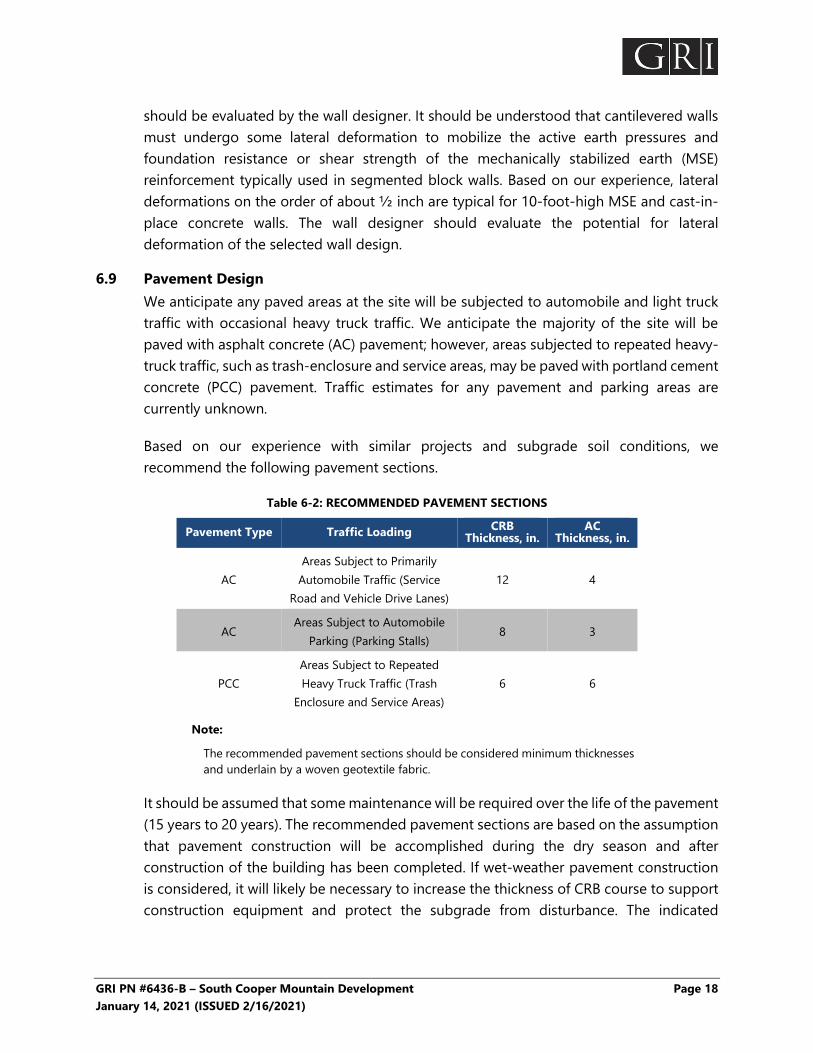
6.9 Pavement Design We anticipate any paved areas at the site will be subjected to automobile and light truck traffic with occasional heavy truck traffic. We anticipate the majority of the site will be paved with asphalt concrete (AC) pavement; however, areas subjected to repeated heavy-truck traffic, such as trash-enclosure and service areas, may be paved with portland cement concrete (PCC) pavement. Traffic estimates for any pavement and parking areas are currently unknown.
Based on our experience with similar projects and subgrade soil conditions, we recommend the following pavement sections.
Table 6-2: RECOMMENDED PAVEMENT SECTIONS
Pavement Type Traffic Loading CRB Thickness, in.
AC Thickness, in.
AC Areas Subject to Primarily
Automobile Traffic (Service Road and Vehicle Drive Lanes)
12 4
AC Areas Subject to Automobile
Parking (Parking Stalls) 8 3
PCC Areas Subject to Repeated Heavy Truck Traffic (Trash
Enclosure and Service Areas) 6 6
Note:
The recommended pavement sections should be considered minimum thicknesses and underlain by a woven geotextile fabric.
It should be assumed that some maintenance will be required over the life of the pavement (15 years to 20 years). The recommended pavement sections are based on the assumption that pavement construction will be accomplished during the dry season and after construction of the building has been completed. If wet-weather pavement construction is considered, it will likely be necessary to increase the thickness of CRB course to support construction equipment and protect the subgrade from disturbance. The indicated

GRI PN #6436-B – South Cooper Mountain Development Page 19 January 14, 2021 (ISSUED 2/16/2021)
sections are not intended to support extensive construction traffic such as forklifts, dump trucks, and concrete trucks. Pavements subject to construction traffic may require repair.
For the above-indicated sections, drainage is an essential aspect of pavement performance. We recommend all paved areas be provided positive drainage to remove surface water and water within the base course. This will be particularly important in cut sections or at low points within the paved areas, such as at catch basins. Effective methods to prevent saturation of the base course materials include providing weepholes in the sidewalls of catch basins, subdrains in conjunction with utility excavations, and separate trench drain systems. To ensure quality materials and construction practices, we recommend the pavement work conform to Oregon Department of Transportation standards.
Prior to placing base-course materials, all pavement areas should be proof rolled with a fully loaded, 10-cubic-yard dump truck. Any soft areas detected by the proof rolling should be overexcavated to firm ground and backfilled with compacted structural fill.
Provided the pavement section is installed in accordance with the recommendations provided above, it is our opinion the site-access areas will support infrequent traffic by an emergency vehicle having a gross vehicle weight of up to 75,000 pounds. For the purposes of this evaluation, “infrequent” can be defined as once a month or less.
7 DESIGN REVIEW AND CONSTRUCTION SERVICES We welcome the opportunity to review and discuss construction plans and specifications for this project as they are being developed. In addition, GRI should be retained to review all geotechnical-related portions of the plans and specifications to evaluate whether they are in conformance with the recommendations provided in our report. To observe compliance with the intent of our recommendations, the design concepts, and the plans and specifications, we are of the opinion all construction operations dealing with earthwork, shoring, and foundations should be observed by a GRI representative. Our construction-phase services will allow for timely design changes if site conditions are encountered that are different from those described in our report. If we do not have the opportunity to confirm our interpretations, assumptions, and analyses during construction, we cannot be responsible for the application of our recommendations to subsurface conditions different from those described in this report.
8 LIMITATIONS This report has been prepared to aid the architect and engineer in the design of this project. The scope is limited to the specific project and location described herein, and our description of the project represents our understanding of the significant aspects of the project relevant to the design and construction of the new foundations and floors. In the

GRI PN #6436-B – South Cooper Mountain Development Page 20 January 14, 2021 (ISSUED 2/16/2021)
Expires 06-2022
event that any changes in the design and location of the project elements as outlined in this report are planned, we should be given the opportunity to review the changes and modify or reaffirm the conclusions and recommendations of this report in writing.
The conclusions and recommendations submitted in this report are based on the data obtained from the explorations made at the locations indicated on Figure 2 and other sources of information discussed in this report. In the performance of subsurface investigations, specific information is obtained at specific locations at specific times. However, it is acknowledged that variations in soil conditions may exist between exploration locations. This report does not reflect any variations that may occur between these explorations. The nature and extent of variation may not become evident until construction. If during construction, subsurface conditions differ from those encountered in the explorations, we should be advised at once so that we can observe and review these conditions and reconsider our recommendations where necessary.
Submitted for GRI,
A. Wesley Spang, PhD, PE, GE Nicholas M. Hatch, PE Marissa P. Rauthause, PE Principal Senior Engineer Project Engineer
This document has been submitted electronically.
GRI PN #6436-B – South Cooper Mountain Development Page 21 January 14, 2021 (ISSUED 2/16/2021)
9 REFERENCES American Society of Civil Engineers, 2016, ASCE 7-16, Minimum design loads for buildings and other structures, Draft Copy, ASCE, Reston, Virginia.
HGSI, August 2, 2018, Geotechnical engineering evaluation of imported fill, South Cooper Mountain multi-family, Beaverton, Oregon, prepared for West Hills Land Development.
Madin, I. P., 2004, Preliminary digital geologic compilation map of the greater Portland urban area, Oregon: Oregon Department of Geology and Mineral Industries, Open-File Report O-04-02, scale 1:24,000.
U.S. Geological Survey (USGS), Unified hazard tool, Conterminous U.S. 2014(v4.0x), accessed 11/16/20 from USGS website: https://earthquake.usgs.gov/hazards/interactive/.
USGS, 2018, U.S. Seismic Design Maps lookup by latitude, longitude, accessed 11/16/20 from USGS website: https://earthquake.usgs.gov/designmaps/us/application.php.

....
...
.. ......
.
..
.... .. .
.
...
.
...
.
.
.. .. . .
.....
.. ..
...
. ... .... ..
.......
.
.
!"
!"
&
;̂
n
n
n
n
n
n
nn
n
n
n
n
n
n
n
650
250
250
350
400
600200
400
250
700
450
450
FlyingK RanchAirport
MeyerRiversideAirpark
SW NORTH DAK A ST
LL M UN RD
I EN D
SW DEKALB ST
SW BULL MOUNTAI RD
SW BEARD RD
S
SW
W ERN ST
SW KATHERIN ST
SW WOODHUE ST
SW HORS TAR
SW SUNRISE LN
SW WINTERGREEN ST
SW GAARDE ST
SW O PREY DR
W BE F BEND R
S BR ISWAY
R C EST D
SMA
ARD DR
MISTLETOE DR
SW SILER RIDGE LN
SW HAWKS BEARD ST
SW C
SW SCHOLLS FERRY RD
SW WEIR RD
¬«210
¬«210
S W
R
SW HIGH HILL LN
SW ALVORD LN
SW TEAL LVD
SW NORA RD
SW BR
SW FINIS LN
SW BROCKMAN ST
SWS
SW WALNUT ST
SW CORMORANT DR
SW WIN ER LR
S
PA
O
SW FO
CLES AVE
SW KEMMER RD
¬«99
W TER
Summer C
Summer C
ala n R r
HeardReservoir
Stark Reservoir
SaintAnthonys
Cem
CooperMountainCem
TualatinValley
BULL MOUNTAIN
Bull Mtn
Cooper Mtn
Kinton
SITE
R IG
VICINITY MAPJAN. 2021 JOB NO. 6436-B FIG. 1
0 1/2 1 MILE
USGS TOPOGRAPHIC MAP BEAVERTON, OREG. (2020)
BRIDGE HOUSINGSOUTH COOPER MOUNTAIN DEVELOPMENT
N

SITE PLANJAN. 2021 JOB NO. 6436-B FIG. 2
0 140 FT
BORING COMPLETED BY GRI (JUNE 27, 2018)
CONE PENETRATION TEST COMPLETED BY GRI (JUNE 27, 2018)
BORING COMPLETED BY GRI (DECEMBER 17, 2020)
DILATOMETER COMPLETED BY GRI (DECEMBER 18, 2020)
DYNAMIC CONE PENETRATION TEST COMPLETED BY GRI (DECEMBER 17, 2020)
SITE PLAN FROM FILE BY GOOGLE EARTH PRO, 2021
70
BRIDGE HOUSINGSOUTH COOPER MOUNTAIN DEVELOPMENTG R I
N
SITE BOUNDARY
B-6
B-5
B-4
DCPT-3
DCPT-2
B-3
DMT-3
DMT-2
DCPT-4
B-1
DMT-4
DCPT-1B-2
CPT-1


GRI PN #6436-B – South Cooper Mountain Development January 14, 2021 (ISSUED 2/16/2021)
APPENDIX A Field Explorations and Laboratory Testing

GRI PN #6436-B – South Cooper Mountain Development Page A-1 January 14, 2021 (ISSUED 2/16/2021)
APPENDIX A
FIELD EXPLORATIONS AND LABORATORY TESTING A.1 FIELD EXPLORATIONS A.1.1 General
Subsurface materials and conditions were initially investigated at the site on June 27, 2018, with two borings, designated B-1 and B-2, and one cone penetration test (CPT) probe, designated CPT-1. Subsequently, GRI completed four additional borings, designated B-3 through B-6; four dilatometer test (DMT) soundings, designated DMT-1 through DMT-4, and four Wildcat dynamic cone penetration test (DCPT) probes, designated DCPT-1 through DCPT-4, at the site between December 17 and 18, 2020. The approximate locations of the explorations completed for this investigation are shown on the Site Plan, Figure 2. Logs of the explorations are provided on Figures 1A through 12A. The field exploration work was coordinated and documented by an experienced member of GRI’s geotechnical engineering staff, who maintained a log of the materials and conditions disclosed during the course of work.
A.1.2 Borings Two borings, designated B-1 and B-2, were advanced to depths of about 29.5 feet and 11 feet, respectively, below existing site grades. The borings were completed with solid-stem drilling techniques using a Simco 2400SK trailer-mounted drill rig provided and operated by Greg Vandehey Soil Sampling of Banks, Oregon. Disturbed and undisturbed soil samples were obtained from the borings at 2.5-foot intervals of depth in the upper 15 feet and at 5-foot intervals below 15 feet. Disturbed soil samples were obtained using a 2-inch-outside-diameter standard split-spoon sampler. Standard penetration tests (SPTs) were conducted by driving the sampler into the soil a distance of 18 inches using a 140-pound hammer dropped 30 inches. The number of blows required to drive the split-spoon sampler the last 12 inches is known as the Standard Penetration Resistance, or SPT N-value. SPT N-values provide a measure of the relative density of granular soils and relative consistency of cohesive soils. Samples obtained from the borings were placed in airtight jars and returned to our laboratory for further classification and testing. In addition, relatively undisturbed samples were collected by pushing 3-inch-outside-diameter Shelby tubes into the undisturbed soil a maximum distance of 24 inches using the hydraulic ram of the drill rig. The soil exposed in the ends of the Shelby tubes was examined and classified in the field. After classification, the tubes were sealed with rubber caps and returned to our laboratory for further examination and testing.
Four borings, designated B-3 through B-6, were advanced to depths of about 12 feet to 30 feet below existing site grades. The borings were completed with direct-push

GRI PN #6436-B – South Cooper Mountain Development Page A-2 January 14, 2021 (ISSUED 2/16/2021)
techniques using a track-mounted Geoprobe 6622CPT provided and operated by Oregon Geotechnical Explorations, Inc., of Keizer, Oregon. Disturbed soil samples were obtained from the borings using geoprobe methods. Geoprobe methods consist of using the geoprobe hammer to ram an outer probing sleeve into the ground with an inner plastic sleeve. The inner plastic sleeve is filled with disturbed soils as the probe is advanced through the soil column, and is removed and cut open after each run to observe the soils recovered. Continuous samples were logged in approximately 5-foot probed runs, and representative samples of the probed runs were placed in airtight jars and returned to our laboratory for further examination and testing.
Logs of the borings are provided on Figures 1A through 6A. Each log presents a descriptive summary of the various types of materials encountered in the boring and notes the depths at which the materials and/or characteristics of the materials change. To the right of the descriptive summary, the numbers and types of samples are indicated. Farther to the right, SPT N-values are shown graphically, along with the natural moisture contents, Torvane shear strength values, Atterberg limits, and percent passing the No. 200 sieve, where applicable. The terms and symbols used to describe the materials encountered in the borings are defined in Tables 1A and 2A and the attached legend.
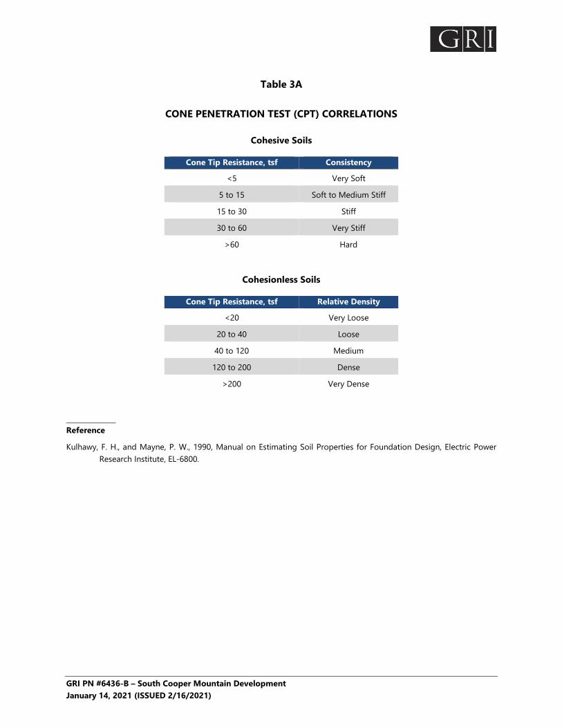
A.1.3 Cone Penetration Test (CPT) Probes One CPT probe, designated CPT-1, was advanced to a depth of about 35 feet using a track-mounted rig provided and operated by Oregon Geotechnical Explorations, Inc., of Keizer, Oregon. During a CPT, a steel cone is forced vertically into the soil at a constant rate of penetration. The force required to cause penetration at a constant rate can be related to the bearing capacity of the soil immediately surrounding the point of the penetrometer cone. This force is measured and recorded every 2 inches. In addition to the cone measurements, measurements are obtained of the magnitude of force required to force a friction sleeve, attached above the cone, through the soil. The force required to move the friction sleeve can be related to the undrained shear strength of fine-grained soils. The dimensionless ratio of sleeve friction to point-bearing capacity provides an indicator of the type of soil penetrated. The cone penetration resistance and sleeve friction can be used to evaluate the relative consistency of cohesionless and cohesive soils, respectively. In addition, a piezometer fitted between the cone and the sleeve measures changes in water pressure as the probe is advanced and can also be used to measure the depth of the top of the groundwater table.
A log of the CPT probe is provided on Figure 7A, which presents a graphical summary of the tip resistance, local (sleeve) friction, friction ratio, pore pressure, and soil behavior type index. The terms used to describe the soils encountered in the probe are defined in Table 3A.
GRI PN #6436-B – South Cooper Mountain Development Page A-3 January 14, 2021 (ISSUED 2/16/2021)
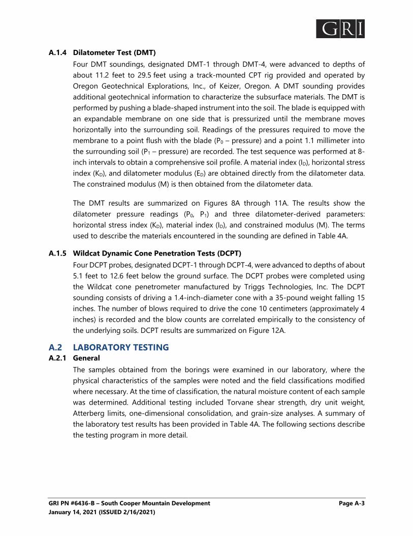
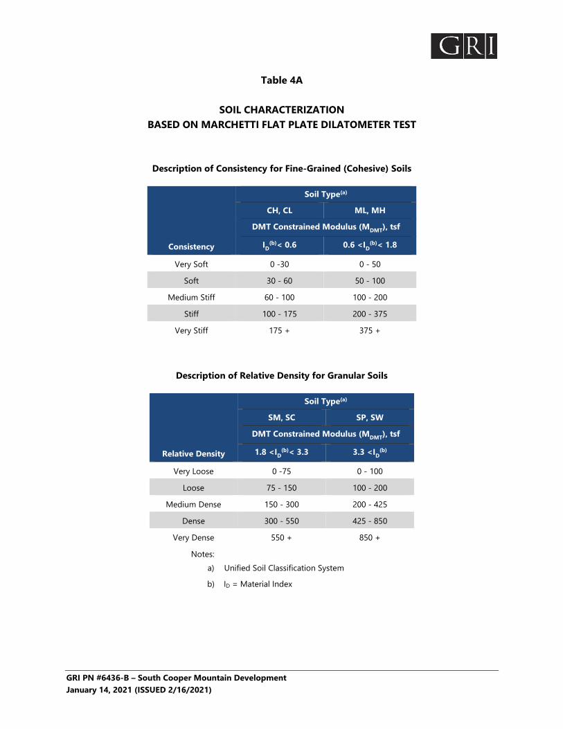
A.1.4 Dilatometer Test (DMT) Four DMT soundings, designated DMT-1 through DMT-4, were advanced to depths of about 11.2 feet to 29.5 feet using a track-mounted CPT rig provided and operated by Oregon Geotechnical Explorations, Inc., of Keizer, Oregon. A DMT sounding provides additional geotechnical information to characterize the subsurface materials. The DMT is performed by pushing a blade-shaped instrument into the soil. The blade is equipped with an expandable membrane on one side that is pressurized until the membrane moves horizontally into the surrounding soil. Readings of the pressures required to move the membrane to a point flush with the blade (P0 – pressure) and a point 1.1 millimeter into the surrounding soil (P1 – pressure) are recorded. The test sequence was performed at 8-inch intervals to obtain a comprehensive soil profile. A material index (ID), horizontal stress index (KD), and dilatometer modulus (ED) are obtained directly from the dilatometer data. The constrained modulus (M) is then obtained from the dilatometer data.
The DMT results are summarized on Figures 8A through 11A. The results show the dilatometer pressure readings (P0, P1) and three dilatometer-derived parameters: horizontal stress index (KD), material index (ID), and constrained modulus (M). The terms used to describe the materials encountered in the sounding are defined in Table 4A.
A.1.5 Wildcat Dynamic Cone Penetration Tests (DCPT) Four DCPT probes, designated DCPT-1 through DCPT-4, were advanced to depths of about 5.1 feet to 12.6 feet below the ground surface. The DCPT probes were completed using the Wildcat cone penetrometer manufactured by Triggs Technologies, Inc. The DCPT sounding consists of driving a 1.4-inch-diameter cone with a 35-pound weight falling 15 inches. The number of blows required to drive the cone 10 centimeters (approximately 4 inches) is recorded and the blow counts are correlated empirically to the consistency of the underlying soils. DCPT results are summarized on Figure 12A.
A.2 LABORATORY TESTING A.2.1 General
The samples obtained from the borings were examined in our laboratory, where the physical characteristics of the samples were noted and the field classifications modified where necessary. At the time of classification, the natural moisture content of each sample was determined. Additional testing included Torvane shear strength, dry unit weight, Atterberg limits, one-dimensional consolidation, and grain-size analyses. A summary of the laboratory test results has been provided in Table 4A. The following sections describe the testing program in more detail.

GRI PN #6436-B – South Cooper Mountain Development Page A-4 January 14, 2021 (ISSUED 2/16/2021)
A.2.2 Natural Moisture Content Natural moisture content determinations were made in conformance with standard ASTM International (ASTM) D2216. The results are summarized on Figures 1A through 6A and in Table 5A.
A.2.3 Grain-Size Analysis
A.2.3.1 Washed-Sieve Method
To assist in classification of the soils, samples of known dry weight were washed over a No. 200 sieve. The material retained on the sieve is oven-dried and weighed. The percentage of material passing the No. 200 sieve is then calculated. The results are summarized on Figures 1A and 3A through 6A and in Table 5A.
A.2.4 Torvane Shear Strength The approximate undrained shear strength of fine-grained soils was determined using a Torvane shear device. The Torvane is a hand-held apparatus with vanes that are inserted into the soil. The torque required to fail the soil in shear around the vanes is measured using a calibrated spring. The results of the Torvane shear-strength tests are summarized on Figures 1A and 2A.
A.2.5 Undisturbed Unit Weight The unit weight, or density, of undisturbed soil samples was determined in the laboratory in conformance with ASTM D2937. The results are summarized on Figure 2A and in Table 5A.
A.2.6 Atterberg Limits Atterberg-limits tests were performed for selected samples of silt and clay in conformance with ASTM D4318. The test results are summarized on the Plasticity Chart, Figure 13A, Figures 4A and 5A, and in Table 5A.
A.2.7 One-Dimensional Consolidation One one-dimensional consolidation test was performed in conformance with ASTM D2435 on a relatively undisturbed soil sample extruded from a Shelby tube. This test provides data on the compressibility of underlying fine-grained soils, necessary for settlement studies. The test results are summarized on Figure 14A in the form of a curve showing percent strain versus applied effective stress. The initial dry unit weight and moisture content of each sample are also shown on the figures.

GRI PN #6436-B – South Cooper Mountain Development January 14, 2021 (ISSUED 2/16/2021)
Table 1A
GUIDELINES FOR CLASSIFICATION OF SOIL
Description of Relative Density for Granular Soil
Relative Density Standard Penetration Resistance,
(N-values) blows/ft
Very Loose 0 - 4
Loose 4 - 10
Medium Dense 10 - 30
Dense 30 - 50
Very Dense over 50
Description of Consistency for Fine-Grained (Cohesive) Soils
Consistency
Standard Penetration Resistance (N-values),
blows/ft
Torvane or Undrained Shear
Strength, tsf
Very Soft 0 - 2 less than 0.125
Soft 2 - 4 0.125 - 0.25
Medium Stiff 4 - 8 0.25 - 0.50
Stiff 8 - 15 0.50 - 1.0
Very Stiff 15 - 30 1.0 - 2.0
Hard over 30 over 2.0
Grain-Size Classification Modifier for Subclassification
Boulders: >12 in. Cobbles: 3-12 in. Gravel: ¼ - ¾ in. (fine) ¾ - 3 in. (coarse) Sand: No. 200 - No. 40 sieve (fine) No. 40 - No. 10 sieve (medium) No. 10 - No. 4 sieve (coarse) Silt/Clay: Pass No. 200 sieve
Adjective
Primary Constituent SAND or GRAVEL
Primary Constituent SILT or CLAY
Percentage of Other Material (By Weight) trace: 5 - 15 (sand, gravel) 5 - 15 (sand, gravel) some: 15 - 30 (sand, gravel) 15 - 30 (sand, gravel)
sandy, gravelly: 30 - 50 (sand, gravel) 30 - 50 (sand, gravel)
trace: <5 (silt, clay) Relationship of clay
and silt determined by plasticity index test
some: 5 - 12 (silt, clay) silty, clayey: 12 - 50 (silt, clay)

GRI PN #6436-B – South Cooper Mountain Development January 14, 2021 (ISSUED 2/16/2021)
Table 2A GUIDELINES FOR CLASSIFICATION OF ROCK
Relative Rock Weathering Scale
Term Field Identification Fresh Crystals are bright. Discontinuities may show some minor surface staining. No discoloration in rock fabric.
Slightly Weathered
Rock mass is generally fresh. Discontinuities are stained and may contain clay. Some discoloration in rock fabric. Decomposition extends up to 1 in. into rock.
Moderately Weathered
Rock mass is decomposed 50% or less. Significant portions of rock show discoloration and weathering effects. Crystals are dull and show visible chemical alteration. Discontinuities are stained and may contain secondary mineral deposits.
Predominantly Decomposed
Rock mass is more than 50% decomposed. Rock can be excavated with geologist’s pick. All discontinuities exhibit secondary mineralization. Complete discoloration of rock fabric. Surface of core is friable and usually pitted due to washing out of highly altered minerals by drilling water.
Decomposed Rock mass is completely decomposed. Original rock “fabric” may be evident. May be reduced to soil with hand pressure.
Relative Rock Hardness Scale
Term
Hardness Designation
Field Identification
Approximate Unconfined
Compressive Strength Extremely
Soft R0 Can be indented with difficulty by thumbnail. May be moldable or friable with finger pressure. < 100 psi
Very Soft R1
Crumbles under firm blows with point of a geology pick. Can be peeled by a pocket knife and scratched with fingernail.
100 - 1,000 psi
Soft R2 Can be peeled by a pocket knife with difficulty. Cannot be scratched with fingernail. Shallow indentation made by firm blow of geology pick.
1,000 - 4,000 psi
Medium Hard R3
Can be scratched by knife or pick. Specimen can be fractured with a single firm blow of hammer/geology pick.
4,000 - 8,000 psi
Hard R4 Can be scratched with knife or pick only with difficulty. Several hard hammer blows required to fracture specimen.
8,000 - 16,000 psi
Very Hard R5
Cannot be scratched by knife or sharp pick. Specimen requires many blows of hammer to fracture or chip. Hammer rebounds after impact.
> 16,000 psi
RQD and Rock Quality
Relation of RQD and Rock Quality Terminology for Planar Surface
RQD (Rock Quality Designation), %
Description of Rock Quality Bedding
Joints and Fractures Spacing
0 - 25 Very Poor Laminated Very Close < 2 in. 25 - 50 Poor Thin Close 2 in. – 12 in. 50 - 75 Fair Medium Moderately Close 12 in. – 36 in. 75 - 90 Good Thick Wide 36 in. – 10 ft 90 - 100 Excellent Massive Very Wide > 10 ft
GRI PN #6436-B – South Cooper Mountain Development January 14, 2021 (ISSUED 2/16/2021)
Table 3A
CONE PENETRATION TEST (CPT) CORRELATIONS
Cohesive Soils
Cone Tip Resistance, tsf Consistency
<5 Very Soft
5 to 15 Soft to Medium Stiff
15 to 30 Stiff
30 to 60 Very Stiff
>60 Hard
Cohesionless Soils
Cone Tip Resistance, tsf Relative Density
<20 Very Loose
20 to 40 Loose
40 to 120 Medium
120 to 200 Dense
>200 Very Dense Reference
Kulhawy, F. H., and Mayne, P. W., 1990, Manual on Estimating Soil Properties for Foundation Design, Electric Power Research Institute, EL-6800.
GRI PN #6436-B – South Cooper Mountain Development January 14, 2021 (ISSUED 2/16/2021)
Table 4A
SOIL CHARACTERIZATION BASED ON MARCHETTI FLAT PLATE DILATOMETER TEST
Description of Consistency for Fine-Grained (Cohesive) Soils
Consistency
Soil Type(a)
CH, CL ML, MH
DMT Constrained Modulus (MDMT), tsf
ID(b)< 0.6 0.6 <ID
(b)< 1.8
Very Soft 0 -30 0 - 50
Soft 30 - 60 50 - 100
Medium Stiff 60 - 100 100 - 200
Stiff 100 - 175 200 - 375
Very Stiff 175 + 375 +
Description of Relative Density for Granular Soils
Relative Density
Soil Type(a)
SM, SC SP, SW
DMT Constrained Modulus (MDMT), tsf
1.8 <ID(b)< 3.3 3.3 <ID
(b)
Very Loose 0 -75 0 - 100
Loose 75 - 150 100 - 200
Medium Dense 150 - 300 200 - 425
Dense 300 - 550 425 - 850
Very Dense 550 + 850 +
Notes: a) Unified Soil Classification System
b) ID = Material Index
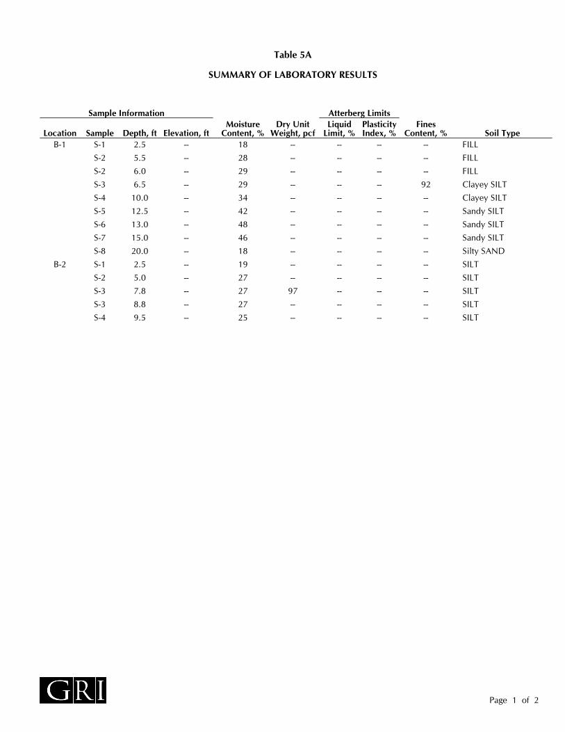
B-1 S-1 2.5 -- 18 -- -- -- -- FILL
S-2 5.5 -- 28 -- -- -- -- FILL
S-2 6.0 -- 29 -- -- -- -- FILL
S-3 6.5 -- 29 -- -- -- 92 Clayey SILT
S-4 10.0 -- 34 -- -- -- -- Clayey SILT
S-5 12.5 -- 42 -- -- -- -- Sandy SILT
S-6 13.0 -- 48 -- -- -- -- Sandy SILT
S-7 15.0 -- 46 -- -- -- -- Sandy SILT
S-8 20.0 -- 18 -- -- -- -- Silty SAND
B-2 S-1 2.5 -- 19 -- -- -- -- SILT
S-2 5.0 -- 27 -- -- -- -- SILT
S-3 7.8 -- 27 97 -- -- -- SILT
S-3 8.8 -- 27 -- -- -- -- SILT
S-4 9.5 -- 25 -- -- -- -- SILT
SUMMARY OF LABORATORY RESULTS
Elevation, ftDepth, ftSampleLocation
Table 5A
Sample InformationDry Unit
Weight, pcfLiquid
Limit, %PlasticityIndex, %
MoistureContent, %
FinesContent, %
Atterberg Limits
Page 1 of 2
Soil Type

B-3 S-1 1.2 -- 36 -- -- -- 87 GRAVELS-2 5.3 -- 54 -- -- -- -- Clayey SILTS-3 7.5 -- 49 -- -- -- -- Clayey SILTS-4 11.1 -- 61 -- -- -- -- Clayey SILT
B-4 S-1 2.5 -- 23 -- -- -- -- FILLS-2 5.3 -- 30 -- -- -- -- FILLS-3 8.5 -- 29 -- 56 35 -- Clayey SILTS-4 12.5 -- 27 -- -- -- -- Clayey SILTS-5 14.0 -- 52 -- -- -- 81 Sandy SILTS-6 17.5 -- 56 -- -- -- -- Sandy SILTS-7 21.0 -- 56 -- -- -- 56 Sandy SILTS-8 24.0 -- 36 -- -- -- -- Sandy SILTS-9 29.0 -- 46 -- -- -- 51 Sandy SILT
B-5 S-1 1.0 -- 23 -- -- -- -- FILLS-2 4.0 -- 25 -- 53 28 -- FILLS-3 5.3 -- 22 -- -- -- 95 FILLS-4 8.0 -- 23 -- -- -- -- Clayey SILTS-5 10.3 -- 23 -- -- -- -- Clayey SILTS-6 12.5 -- 28 -- -- -- -- Clayey SILTS-7 17.0 -- 31 -- -- -- -- Clayey SILTS-8 20.0 -- 32 -- -- -- -- Clayey SILTS-9 24.0 -- 48 -- -- -- 65 Sandy SILTS-10 27.0 -- 27 -- -- -- 62 Sandy SILTS-11 27.5 -- 39 -- -- -- -- Sandy SILT
B-6 S-1 1.0 -- 4 -- -- -- -- FILLS-2 5.3 -- 9 -- -- -- -- Clayey SILTS-3 10.3 -- 26 -- -- -- -- Clayey SILTS-4 13.0 -- 47 -- -- -- 59 Sandy SILTS-5 17.0 -- 17 -- -- -- -- BASALT
Table 5A
SUMMARY OF LABORATORY RESULTS
Sample Information Atterberg Limits
Page 2 of 2
Soil TypeFines
Content, %PlasticityIndex, %
LiquidLimit, %
Dry UnitWeight, pcf
MoistureContent, %Elevation, ftSampleLocation Depth, ft

GRAVEL; clean to some silt, clay, and sand
Sandy GRAVEL; clean to some silt and clay
Silty GRAVEL; up to some clay and sand
Clayey SAND; up to some silt and gravel
Gravelly CLAY; up to some silt and sand
Sandy CLAY; up to some silt and gravel
Silty CLAY; up to some sand and gravel
Symbol Description
Flush-mount monument set in concrete
Concrete, well casing shown where applicable
Filter pack, machine-slotted well casing shownwhere applicable
1-in.-diameter solid PVC
FIELD MEASUREMENTSTypical Description
Groundwater level after drilling and datemeasured
Symbol Typical Description
BASALT
MUDSTONE
SILTSTONE
PEAT
Symbol
FILL
Clayey GRAVEL; up to some silt and sand
SAND; clean to some silt, clay, and gravel
SILT; up to some clay, sand, and gravel
Gravelly SILT; up to some clay and sand
Sandy SILT; up to some clay and gravel
Clayey SILT; up to some sand and gravel
CLAY; up to some silt, sand, and gravel
Grab Sample
Rock core sample interval
Sonic core sample interval
INSTALLATION SYMBOLSSymbol
Bentonite seal, well casing shown if applicable
Vibrating-wire pressure transducer
SymbolBEDROCK SYMBOLS
SOIL SYMBOLSTypical Description
SAMPLER SYMBOLSSampler DescriptionSymbol
LANDSCAPE MATERIALS
Gravelly SAND; clean to some silt and clay
Silty SAND; up to some clay and gravel
Shelby tube sampler with recovery(ASTM D1587)
Grout, vibrating-wire transducer cable shown whereapplicable
1-in.-diameter hand-slotted PVC
Grout, inclinometer casing shown where applicable
Groundwater level during drilling and datemeasured
SANDSTONE
SURFACE MATERIAL SYMBOLSSymbol Typical Description
BORING AND TEST PIT LOG LEGEND
Rock quality designation (RQD, %)
Asphalt concrete PAVEMENT
Portland cement concrete PAVEMENT
Crushed rock BASE COURSE
2.0 in. O.D. split-spoon sampler and StandardPenetration Test with recovery (ASTM D1586)
3.0 in. O.D. split-spoon sampler with recovery(ASTM D3550)
Push probe sample interval
Rock/sonic core or push probe recovery (%)
BO
RIN
G A
ND
TE
ST
PIT
LO
G L
EG
EN
D G
RI D
AT
A T
EM
PLA
TE
.GD
T 8
/20/
20

Clayey SILT to silty CLAY, up to a trace offine-grained sand, brown, medium stiff to stiff (Fill)
---some fine-grained sand below 5 ft
Clayey SILT to silty CLAY, trace fine-grained sand,brown to red-brown, stiff (Residual Soil)
---trace fine- to medium-grained sand below 10 ft
Sandy SILT, red-brown mottled black and orange,stiff to hard, fine- to coarse-grained sand, relict rockstructure, contains gravel-sized basalt fragments(Decomposed Basalt)---dark brown below 13 ft
Silty SAND, dark brown, medium dense, fine tocoarse grained, relict rock structure, containsgravel-sized fragments of decomposed basalt(Decomposed Basalt)
BASALT, gray, decomposed, extremely soft to verysoft, R0 to R1 (Columbia River Basalt)
(6/27/2018)
Energy Ratio:
SAM
PLE
NO
.
Simco 2400SK Trailer-Mounted Drill Rig
Surface Elevation:
Hammer Type:
1.0
50
Weight:
Not Available INST
ALLA
TIO
N
0.5
Logged By:
Drilling Method:6/27/18
INST
ALLA
TIO
N
BORING B-14 in.
PLASTIC LIMIT, %LIQUID LIMIT, %FINES CONTENT, %
BLOWS PER FOOTMOISTURE CONTENT, %
0
Solid-Stem Auger
Drilled by:
140 lbDrop:
See Legend for Explanation of Symbols
DEP
TH, F
T
SAM
PLE
TYPE
BLO
W C
OU
NT
Date Started:
Note:
N. Utevsky Greg Vandehey Soil Sampling
DEP
TH, F
T
Equipment:
GR
APH
IC L
OG
Manual
Hole Diameter:
CLASSIFICATION OF MATERIAL
30 in.
FIG. 1A
TORVANE SHEAR STRENGTH, TSFUNDRAINED SHEAR STRENGTH, TSF
COMMENTS ANDADDITIONAL TESTS
GPS Coordinates: 45.42901° N -122.85502° W (WGS 84)
GR
I BO
RIN
G L
OG
(G
PS
) -
NO
ELE
V G
RI D
AT
A T
EM
PLA
TE
.GD
T 1
/12/
21
S-1
S-2
S-3
S-4
S-5
S-6
S-7
S-8
S-9
S-10
235
345
468
81018
182120
121415
50/5.5"
2250/5.5"
6.5
12.5
20.0
25.0
29.5
15.8 ft (6/27/2018)
JAN. 2021
5
10
15
20
25
30
35
40
JOB NO. 6128
0 100
8
9
14
28
41
29
50/5.5"
22-50/5.5"
0.300.30
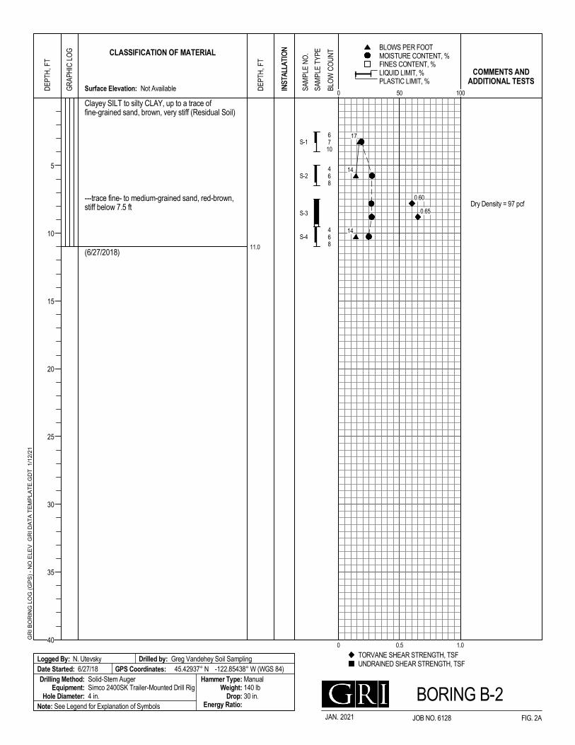
Clayey SILT to silty CLAY, up to a trace offine-grained sand, brown, very stiff (Residual Soil)
---trace fine- to medium-grained sand, red-brown,stiff below 7.5 ft
(6/27/2018)
Dry Density = 97 pcf
Energy Ratio:
SAM
PLE
NO
.
Simco 2400SK Trailer-Mounted Drill Rig
Surface Elevation:
Hammer Type:
1.0
50
Weight:
Not Available INST
ALLA
TIO
N
0.5
Logged By:
Drilling Method:6/27/18
INST
ALLA
TIO
N
BORING B-24 in.
PLASTIC LIMIT, %LIQUID LIMIT, %FINES CONTENT, %
BLOWS PER FOOTMOISTURE CONTENT, %
0
Solid-Stem Auger
Drilled by:
140 lbDrop:
See Legend for Explanation of Symbols
DEP
TH, F
T
SAM
PLE
TYPE
BLO
W C
OU
NT
Date Started:
Note:
N. Utevsky Greg Vandehey Soil Sampling
DEP
TH, F
T
Equipment:
GR
APH
IC L
OG
Manual
Hole Diameter:
CLASSIFICATION OF MATERIAL
30 in.
FIG. 2A
TORVANE SHEAR STRENGTH, TSFUNDRAINED SHEAR STRENGTH, TSF
COMMENTS ANDADDITIONAL TESTS
GPS Coordinates: 45.42937° N -122.85438° W (WGS 84)
GR
I BO
RIN
G L
OG
(G
PS
) -
NO
ELE
V G
RI D
AT
A T
EM
PLA
TE
.GD
T 1
/12/
21
S-1
S-2
S-3
S-4
6710
468
46811.0
JAN. 2021
5
10
15
20
25
30
35
40
JOB NO. 6128
0 100
17
14
14
0.60
0.65
0.60
0.65

Crushed rock SURFACING (24 in.)
Clayey SILT to silty CLAY, trace fine- tocoarse-grained sand, red-brown (Residual Soil)
---black mottling below 5 ft
(12/17/2020)
Refusal encountered at 12 ft
Logged By:
Drilling Method:12/17/20
INST
ALLA
TIO
N
2 in.
PLASTIC LIMIT, %LIQUID LIMIT, %FINES CONTENT, %
BLOWS PER FOOTMOISTURE CONTENT, %
0
Direct Push Probe
Drilled by:
Drop:Energy Ratio:
SAM
PLE
NO
.
Surface Elevation:
Hammer Type:
1.0
50
Weight:
Not Available INST
ALLA
TIO
N
0.5
See Legend for Explanation of Symbols
DEP
TH, F
T
SAM
PLE
TYPE
BLO
W C
OU
NT
Date Started:
Note:
M. Rauthause Oregon Geotechncial Explorations
DEP
TH, F
T
Equipment:
GR
APH
IC L
OG
Hole Diameter:
CLASSIFICATION OF MATERIAL
TORVANE SHEAR STRENGTH, TSFUNDRAINED SHEAR STRENGTH, TSF
COMMENTS ANDADDITIONAL TESTS
GPS Coordinates: Not Available
BORING B-3FIG. 3A
GR
I BO
RIN
G L
OG
(G
PS
) -
NO
ELE
V G
RI D
AT
A T
EM
PLA
TE
.GD
T 1
/14/
21
S-1
R-1
S-2
R-2S-3
R-3S-4
2.0
12.0
11.0 ft (12/17/2020)
JAN. 2021 JOB NO. 6436B
5
10
15
20
25
30
35
40
0 100
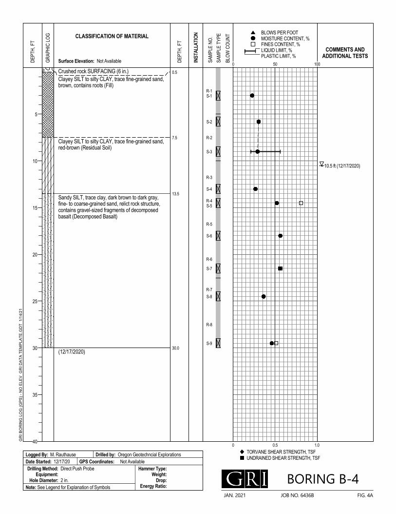
Crushed rock SURFACING (6 in.)Clayey SILT to silty CLAY, trace fine-grained sand,brown, contains roots (Fill)
Clayey SILT to silty CLAY, trace fine-grained sand,red-brown (Residual Soil)
Sandy SILT, trace clay, dark brown to dark gray,fine- to coarse-grained sand, relict rock structure,contains gravel-sized fragments of decomposedbasalt (Decomposed Basalt)
(12/17/2020)
Logged By:
Drilling Method:12/17/20
INST
ALLA
TIO
N
2 in.
PLASTIC LIMIT, %LIQUID LIMIT, %FINES CONTENT, %
BLOWS PER FOOTMOISTURE CONTENT, %
0
Direct Push Probe
Drilled by:
Drop:Energy Ratio:
SAM
PLE
NO
.
Surface Elevation:
Hammer Type:
1.0
50
Weight:
Not Available INST
ALLA
TIO
N
0.5
See Legend for Explanation of Symbols
DEP
TH, F
T
SAM
PLE
TYPE
BLO
W C
OU
NT
Date Started:
Note:
M. Rauthause Oregon Geotechncial Explorations
DEP
TH, F
T
Equipment:
GR
APH
IC L
OG
Hole Diameter:
CLASSIFICATION OF MATERIAL
TORVANE SHEAR STRENGTH, TSFUNDRAINED SHEAR STRENGTH, TSF
COMMENTS ANDADDITIONAL TESTS
GPS Coordinates: Not Available
BORING B-4FIG. 4A
GR
I BO
RIN
G L
OG
(G
PS
) -
NO
ELE
V G
RI D
AT
A T
EM
PLA
TE
.GD
T 1
/14/
21
R-1S-1
S-2
R-2
S-3
R-3
S-4
R-4S-5
R-5
S-6
R-6
S-7
R-7
S-8
R-8
S-9
0.5
7.5
13.5
30.0
10.5 ft (12/17/2020)
JAN. 2021 JOB NO. 6436B
5
10
15
20
25
30
35
40
0 100

Clayey SILT to silty CLAY, trace fine-grained sand,brown to dark brown, scattered crushed rock inupper 12 in. (Fill)
Clayey SILT to silty CLAY, trace fine-grained sand,brown (Residual Soil)
---trace fine- to medium-grained sand, red-brownbelow 18.5 ft
Sandy SILT, brown, fine- to coarse-grained sand,relict rock structure, contains gravel-sizedfragments of decomposed basalt (DecomposedBasalt)
(12/17/2020)
Logged By:
Drilling Method:12/17/20
INST
ALLA
TIO
N
2 in.
PLASTIC LIMIT, %LIQUID LIMIT, %FINES CONTENT, %
BLOWS PER FOOTMOISTURE CONTENT, %
0
Direct Push Probe
Drilled by:
Drop:Energy Ratio:
SAM
PLE
NO
.
Surface Elevation:
Hammer Type:
1.0
50
Weight:
Not Available INST
ALLA
TIO
N
0.5
See Legend for Explanation of Symbols
DEP
TH, F
T
SAM
PLE
TYPE
BLO
W C
OU
NT
Date Started:
Note:
M. Rauthause Oregon Geotechncial Explorations
DEP
TH, F
T
Equipment:
GR
APH
IC L
OG
Hole Diameter:
CLASSIFICATION OF MATERIAL
TORVANE SHEAR STRENGTH, TSFUNDRAINED SHEAR STRENGTH, TSF
COMMENTS ANDADDITIONAL TESTS
GPS Coordinates: Not Available
BORING B-5FIG. 5A
GR
I BO
RIN
G L
OG
(G
PS
) -
NO
ELE
V G
RI D
AT
A T
EM
PLA
TE
.GD
T 1
/14/
21
S-1
R-1
S-2
S-3
R-2
S-4
S-5
R-3
S-6
R-4
S-7
R-5S-8
R-6
S-9
R-7
S-10S-11
7.0
23.0
28.5
10.0 ft (12/17/2020)
JAN. 2021 JOB NO. 6436B
5
10
15
20
25
30
35
40
0 100

Crushed rock SURFACING (12 in.)
Clayey SILT to silty CLAY, trace fine-grained sand,brown (Fill)
Clayey SILT to silty CLAY, trace fine-grained sand,red-brown (Residual Soil)
Sandy SILT, red-brown mottled gray, fine- tocoarse-grained sand, relict rock structure, containsgravel-sized fragments of decomposed basalt(Decomposed Basalt)
BASALT, gray, decomposed, extremely soft to verysoft, R0 to R1 (Columbia River Basalt)
(12/17/2020)
Refusal encountered at 18.5 ft
Logged By:
Drilling Method:12/17/20
INST
ALLA
TIO
N
2 in.
PLASTIC LIMIT, %LIQUID LIMIT, %FINES CONTENT, %
BLOWS PER FOOTMOISTURE CONTENT, %
0
Direct Push Probe
Drilled by:
Drop:Energy Ratio:
SAM
PLE
NO
.
Surface Elevation:
Hammer Type:
1.0
50
Weight:
Not Available INST
ALLA
TIO
N
0.5
See Legend for Explanation of Symbols
DEP
TH, F
T
SAM
PLE
TYPE
BLO
W C
OU
NT
Date Started:
Note:
M. Rauthause Oregon Geotechncial Explorations
DEP
TH, F
T
Equipment:
GR
APH
IC L
OG
Hole Diameter:
CLASSIFICATION OF MATERIAL
TORVANE SHEAR STRENGTH, TSFUNDRAINED SHEAR STRENGTH, TSF
COMMENTS ANDADDITIONAL TESTS
GPS Coordinates: Not Available
BORING B-6FIG. 6A
GR
I BO
RIN
G L
OG
(G
PS
) -
NO
ELE
V G
RI D
AT
A T
EM
PLA
TE
.GD
T 1
/14/
21
S-1
R-1
S-2
R-2
S-3
R-3
S-4
R-4
S-5
1.0
5.0
12.0
15.0
18.5
11.0 ft (12/17/2020)
JAN. 2021 JOB NO. 6436B
5
10
15
20
25
30
35
40
0 100

R IG
JAN 2021 JOB NO. 6436-B FIG. 7A
Observed By: Advanced By:Date Started:Coordinates:
Ground Surface Elevation:CONE PENETRATION TEST CPT-1
GRI / CPT-1 / 12250 SW 175th BeavertonOPERATOR: OGE BBCONE ID: DDG1452HOLE NUMBER: CPT-1TEST DATE: 6/27/2018 1:26:01 PMTOTAL DEPTH: 35.433 ft
Depth(ft)
SPT N60(UNITLESS)0 800
5
10
15
20
25
30
35
40
SBT(UNITLESS)
1 sensitive fine grained 2 organic material 3 clay
4 silty clay to clay 5 clayey silt to silty clay 6 sandy silt to clayey silt
7 silty sand to sandy silt 8 sand to silty sand 9 sand
10 gravelly sand to sand 11 very stiff fine grained (*) 12 sand to clayey sand (*)
*SBT/SPT CORRELATION: UBC-1983
0 12
Tip (Qc)(tsf)0 300
Sleeve (Fs)(tsf)0 10
FR (Fs/Qc)(%)0 7
PP (U2)(psi)-10 80
Oregon Geotechnical Explorations, Inc.N. Utevsky06/27/18
Not AvailableNot Available

JAN. 2021 JOB NO. 6436-B FIG. 8A
DILATOMETER SOUNDING (DMT-1)
0 5 10 15 20 25
P0 , P1 , tsf
20
15
10
5
0D
epth
, ft
0.1 1 10
ID
0 10 20 30 40 50 60 70
KD
0 250 500 750 1,000 1,250
M, tsf
6436B - South Cooper Mountain DevelopmentDilatometer Sounding DMT-1
P0
P1

JAN. 2021 JOB NO. 6436-B FIG. 9A
DILATOMETER SOUNDING (DMT-2)
0 5 10 15 20 25
P0 , P1 , tsf
30
25
20
15
10
5
0D
epth
, ft
0.1 1 10
ID
0 10 20 30 40 50 60 70
KD
0 500 1,000 1,500 2,000
M, tsf
6436B - South Cooper Mountain DevelopmentDilatometer Sounding DMT-2
P0
P1
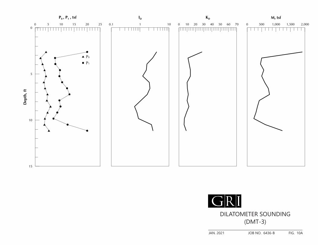
JAN. 2021 JOB NO. 6436-B FIG. 10A
DILATOMETER SOUNDING (DMT-3)
0 5 10 15 20 25
P0 , P1 , tsf
15
10
5
0D
epth
, ft
0.1 1 10
ID
0 10 20 30 40 50 60 70
KD
0 500 1,000 1,500 2,000
M, tsf
6436B - South Cooper Mountain DevelopmentDilatometer Sounding DMT-3
P0
P1

JAN. 2021 JOB NO. 6436-B FIG. 11A
DILATOMETER SOUNDING (DMT-4)
0 5 10 15 20 25
P0 , P1 , tsf
15
10
5
0
Dep
th, f
t
0.1 1 10 100
ID
0 10 20 30 40 50 60 70
KD
0 500 1,000 1,500
M, tsf
6436B - South Cooper Mountain DevelopmentDilatometer Sounding DMT-4
P0
P1

JAN. 2021 JOB NO. 6436-B FIG. 12A
DYNAMIC CONE PENETRATION TESTS (DCPT-1 through DCPT-4)
0 10 20 30 40 50 60 70 80 90 100
Dynamic Cone Penetration Test (DCPT), blows/10 cm
15
14
13
12
11
10
9
8
7
6
5
4
3
2
1
0De
pth,
ft
0 10 20 30 40 50 60 70 80 90 100Dynamic Cone Penetration Test (DCPT), blows/10 cm
6436-B - South Cooper Mountain DevelopmentDCPT 1 though DCPT 4
DCPT-1DCPT-2DCPT-3DCPT-4

0
10
20
30
40
50
60
0 10 20 30 40 50 60 70 80 90 100
S-3
S-2
8.5
4.0
Silty CLAY, trace fine-grained sand, red-brown(Residual Soil)
Silty CLAY, trace fine-grained sand, brown (Fill)
Classification PL
35
28
29
25
Sample MC, %
PLA
STIC
ITY
IND
EX, %
LIQUID LIMIT, %
Location Depth, ft
PLASTICITY CHART
B-4
B-5
LL PI
56
53
21
25
OL
ML
CL
INORGANIC CLAYEY SILTS TO VERY FINESANDS OF SLIGHT PLASTICITY
INORGANIC CLAYS OF HIGH PLASTICITY
UNIFIED SOIL CLASSIFICATIONFINE-GRAINED SOIL GROUPS
GROUPSYMBOL
GROUPSYMBOL
OH
MH
CH
ORGANIC SILTS AND ORGANIC SILTYCLAYS OF LOW PLASTICITY
AT
TE
RB
ER
G-P
LAS
TIC
ITY
2 P
ER
PA
GE
GR
I DA
TA
TE
MP
LAT
E.G
DT
1/1
2/21
CH
CL
MH or OH
CL-MLML or OL
INORGANIC CLAYS OF LOW TO MEDIUMPLASTICITY
ORGANIC CLAYS OF MEDIUM TO HIGHPLASTICITY, ORGANIC SILTS
INORGANIC SILTS AND CLAYEY SILT
UNIFIED SOIL CLASSIFICATIONFINE-GRAINED SOIL GROUPS
JOB NO. 6436BJAN. 2021 FIG. 13A

0
5
10
15
20
250.01 0.1 1 10 100
STR
AIN
, %
STRESS, TSF
93 27
Initial
CO
NS
OL
ST
RA
IN G
RI-
0 T
O 2
5-1
PE
R P
AG
E G
RI D
AT
A T
EM
PLA
TE
.GD
T 1
/12
/21
Location Sample MC, %, pcfClassification
SILT, some fine-grained sand, brown, medium stiff5.8S-2B-1
CONSOLIDATION TESTJOB NO. 6128JAN. 2021 FIG. 14A
Depth, ft