Auditac tg3 system recognition for field visit
25
1 Technical guides for owner/manager of an air conditioning system : volume 3 System recognition guideline for field visit
-
Upload
green-bridge -
Category
Business
-
view
552 -
download
4
description
Transcript of Auditac tg3 system recognition for field visit
1
Technical guides for owner/manager of an air conditioning system : volume 3
System recognition guideline for field visit
2
Authors of this volume Jerome ADNOT (Armines, France) Daniela BORY (Armines, France) Maxime DUPONT (Armines, France) �
The sole responsibility for the content of this publication lies with the authors. It does not represent the opinion of the European Communities. The European Commission is not responsible for any use that may be made of the information contained therein.
AustriaAustrian Energy Agency
BelgiumUniversité de Liège
ItalyPolitecnico di Torino
PortugalUniversity of Porto
AustriaAustrian Energy Agency
AustriaAustrian Energy Agency
BelgiumUniversité de Liège
BelgiumUniversité de Liège
ItalyPolitecnico di Torino
ItalyPolitecnico di Torino
PortugalUniversity of Porto
PortugalUniversity of Porto
SloveniaUniversity of Ljubljana
UKAssociation of Building
Engineers
BRE (Building Research Establishment Ltd)
Welsh School of Architecture
SloveniaUniversity of Ljubljana
SloveniaUniversity of Ljubljana
UKAssociation of Building
Engineers
UKAssociation of Building
Engineers
BRE (Building Research Establishment Ltd)
BRE (Building Research Establishment Ltd)
Welsh School of Architecture
Welsh School of Architecture
Eurovent-CertificationEurovent-Certification
Team
France (Project coordinator)Armines - Mines de Paris
France (Project coordinator)Armines - Mines de Paris
3
1
System recognition guideline for field visit
Different types of air conditioning system have inherently different energy characteristics and options for improvement (or deterioration), so the correct identification of the system type is important. The scope of this guide is to illustrate to the owner or manager of an air conditioning plant how to produce an inventory of the equipment in place by answering straightforward non-specialist questions. These can be answered by walking through the technical rooms and the building and reviewing existing documents. With this inventory an audit or inspection becomes more straightforward. There are two parts to the process – to distinguish between different system types and to identify the type of heat rejection employed. This guide starts with an introduction about the air conditioning systems in general. Following this, two procedures are presented in order to separately define the air conditioning system and the condensing system. The methods are developed through simple questions of which the answer can be easily given observing the system in place. Depending on the subsequent answers, a unique statement of the type about the system type in place is reached. Based on the field observations, and on past documentation, the manager can prepare an updated basic documentation for air conditioning plant including all documents that could and should available for an auditor or an inspector to come.
1 The sole responsibility for the content of this document lies with the authors. It does not represent the opinion of the Community. The European Commission is not responsible for any use that may be made of the information contained therein.
4
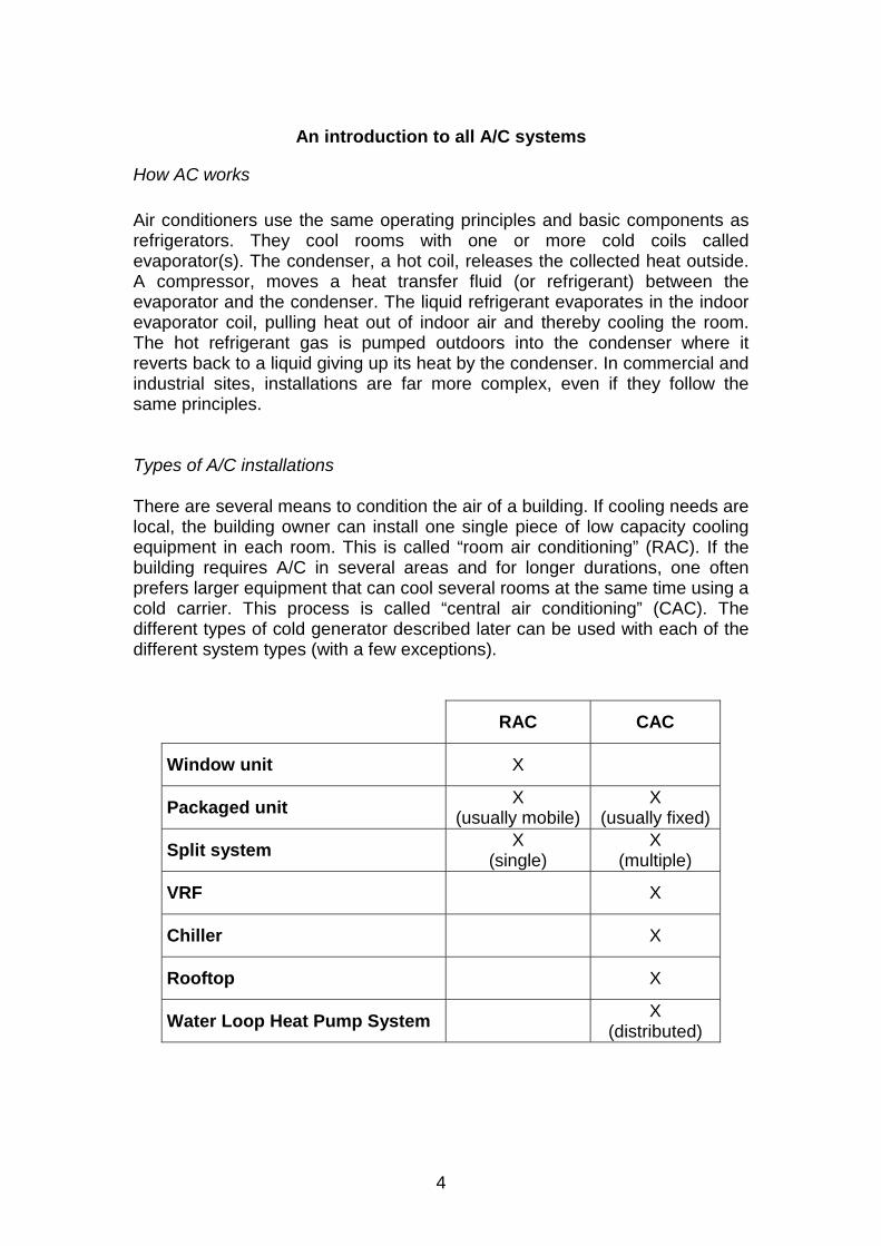
An introduction to all A/C systems
How AC works Air conditioners use the same operating principles and basic components as refrigerators. They cool rooms with one or more cold coils called evaporator(s). The condenser, a hot coil, releases the collected heat outside. A compressor, moves a heat transfer fluid (or refrigerant) between the evaporator and the condenser. The liquid refrigerant evaporates in the indoor evaporator coil, pulling heat out of indoor air and thereby cooling the room. The hot refrigerant gas is pumped outdoors into the condenser where it reverts back to a liquid giving up its heat by the condenser. In commercial and industrial sites, installations are far more complex, even if they follow the same principles. Types of A/C installations There are several means to condition the air of a building. If cooling needs are local, the building owner can install one single piece of low capacity cooling equipment in each room. This is called “room air conditioning” (RAC). If the building requires A/C in several areas and for longer durations, one often prefers larger equipment that can cool several rooms at the same time using a cold carrier. This process is called “central air conditioning” (CAC). The different types of cold generator described later can be used with each of the different system types (with a few exceptions).
RAC CAC
Window unit X
Packaged unit X (usually mobile)
X (usually fixed)
Split system X (single)
X (multiple)
VRF X
Chiller X
Rooftop X
Water Loop Heat Pump System X (distributed)
5
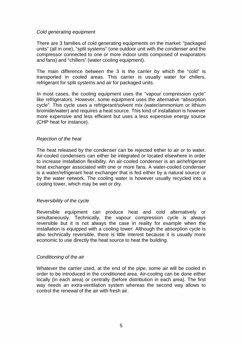
Cold generating equipment There are 3 families of cold generating equipments on the market: “packaged units” (all in one), “split systems” (one outdoor unit with the condenser and the compressor connected to one or more indoor units composed of evaporators and fans) and “chillers” (water cooling equipment). The main difference between the 3 is the carrier by which the “cold” is transported in cooled areas. This carrier is usually water for chillers, refrigerant for split systems and air for packaged units. In most cases, the cooling equipment uses the “vapour compression cycle” like refrigerators. However, some equipment uses the alternative “absorption cycle”. This cycle uses a refrigerant/solvent mix (water/ammonium or lithium bromide/water) and requires a heat source. This kind of installation is however more expensive and less efficient but uses a less expensive energy source (CHP heat for instance). Rejection of the heat The heat released by the condenser can be rejected either to air or to water. Air-cooled condensers can either be integrated or located elsewhere in order to increase installation flexibility. An air-cooled condenser is an air/refrigerant heat exchanger associated with one or more fans. A water-cooled condenser is a water/refrigerant heat exchanger that is fed either by a natural source or by the water network. The cooling water is however usually recycled into a cooling tower, which may be wet or dry. Reversibility of the cycle Reversible equipment can produce heat and cold alternatively or simultaneously. Technically, the vapour compression cycle is always reversible but it is not always the case in reality for example when the installation is equipped with a cooling tower: Although the absorption cycle is also technically reversible, there is little interest because it is usually more economic to use directly the heat source to heat the building. Conditioning of the air Whatever the carrier used, at the end of the pipe, some air will be cooled in order to be introduced in the conditioned area. Air-cooling can be done either locally (in each area) or centrally (before distribution in each area). The first way needs an extra-ventilation system whereas the second way allows to control the renewal of the air with fresh air.
6
The control system Any installation is equipped with sensors (temperature, humidity, air and water flows) and a control system in order to be able to work correctly and to choose the comfort level. The number of sensors depends directly on the complexity of the installation and the flexibility in the comfort level. In addition, clocks, scheduling tools or occupancy sensors can be added in each area in order to manage the comfort and save energy more efficiently. It is even possible that A/C equipments be managed by a building management system (BMS) that can also be in charge of heating, lighting or other electrical devices.
7
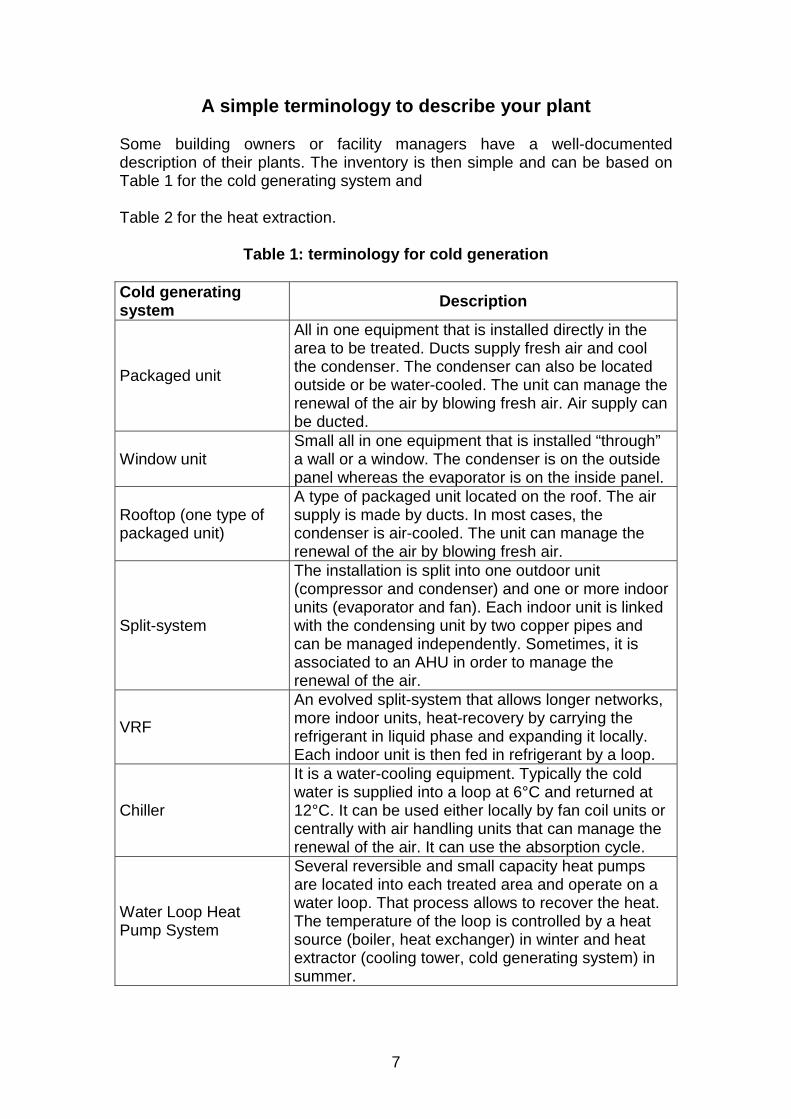
A simple terminology to describe your plant Some building owners or facility managers have a well-documented description of their plants. The inventory is then simple and can be based on Table 1 for the cold generating system and Table 2 for the heat extraction.
Table 1: terminology for cold generation
Cold generating system Description
Packaged unit
All in one equipment that is installed directly in the area to be treated. Ducts supply fresh air and cool the condenser. The condenser can also be located outside or be water-cooled. The unit can manage the renewal of the air by blowing fresh air. Air supply can be ducted.
Window unit Small all in one equipment that is installed “through” a wall or a window. The condenser is on the outside panel whereas the evaporator is on the inside panel.
Rooftop (one type of packaged unit)
A type of packaged unit located on the roof. The air supply is made by ducts. In most cases, the condenser is air-cooled. The unit can manage the renewal of the air by blowing fresh air.
Split-system
The installation is split into one outdoor unit (compressor and condenser) and one or more indoor units (evaporator and fan). Each indoor unit is linked with the condensing unit by two copper pipes and can be managed independently. Sometimes, it is associated to an AHU in order to manage the renewal of the air.
VRF
An evolved split-system that allows longer networks, more indoor units, heat-recovery by carrying the refrigerant in liquid phase and expanding it locally. Each indoor unit is then fed in refrigerant by a loop.
Chiller
It is a water-cooling equipment. Typically the cold water is supplied into a loop at 6°C and returned at 12°C. It can be used either locally by fan coil units or centrally with air handling units that can manage the renewal of the air. It can use the absorption cycle.
Water Loop Heat Pump System
Several reversible and small capacity heat pumps are located into each treated area and operate on a water loop. That process allows to recover the heat. The temperature of the loop is controlled by a heat source (boiler, heat exchanger) in winter and heat extractor (cooling tower, cold generating system) in summer.
8
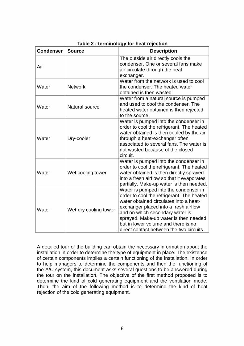
Table 2 : terminology for heat rejection Condenser Source Description
Air
The outside air directly cools the condenser. One or several fans make air circulate through the heat exchanger.
Water Network Water from the network is used to cool the condenser. The heated water obtained is then wasted.
Water Natural source
Water from a natural source is pumped and used to cool the condenser. The heated water obtained is then rejected to the source.
Water Dry-cooler
Water is pumped into the condenser in order to cool the refrigerant. The heated water obtained is then cooled by the air through a heat-exchanger often associated to several fans. The water is not wasted because of the closed circuit.
Water Wet cooling tower
Water is pumped into the condenser in order to cool the refrigerant. The heated water obtained is then directly sprayed into a fresh airflow so that it evaporates partially. Make-up water is then needed.
Water Wet-dry cooling tower
Water is pumped into the condenser in order to cool the refrigerant. The heated water obtained circulates into a heat-exchanger placed into a fresh airflow and on which secondary water is sprayed. Make-up water is then needed but in lower volume and there is no direct contact between the two circuits.
A detailed tour of the building can obtain the necessary information about the installation in order to determine the type of equipment in place. The existence of certain components implies a certain functioning of the installation. In order to help managers to determine the components and then the functioning of the A/C system, this document asks several questions to be answered during the tour on the installation. The objective of the first method proposed is to determine the kind of cold generating equipment and the ventilation mode. Then, the aim of the following method is to determine the kind of heat rejection of the cold generating equipment.
9
A 5 STEPS METHOD TO DETERMINE THE TYPE OF INSIDE HEAT EXTRACTION FROM INSIDE ROOMS OF AN AIR-
CONDITIONING SYSTEM Step 1: Is the cold generating system used for several zones? (locate the compressor and relate them to zones) If different zones are cooled by only one cold generating system, the installation is centralised whereas it is decentralised when each zone or room is equipped with one cold generating equipment. Step 2: Is there a “fluid link” between each cold generating equipments ? A fluid link usually transfers the “cold”. Therefore, when there is a fluid link, we have usually a centralised system. However, water loop heat pump systems (WLHPS) consist of one heat pump per area which are linked by a water loop which does not carry the cold. This kind of installation is also considered as a central air conditioning system. On the other hand, when there is no “fluid link” between all cold generating equipments and cooled spaces, the installation is totally decentralised. Such a decentralised installation can be based on “packaged units” (mobile or not), “window units” (fixed) or “split systems” (outdoor and indoor units).
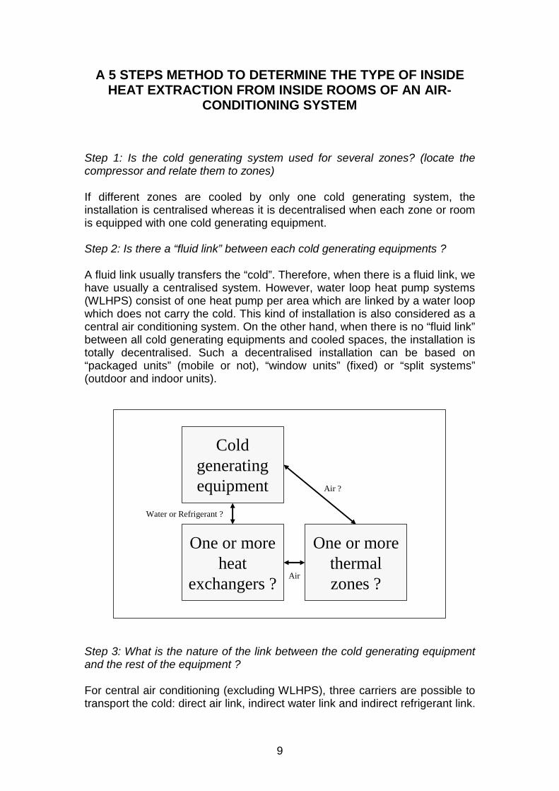
Step 3: What is the nature of the link between the cold generating equipment and the rest of the equipment ? For central air conditioning (excluding WLHPS), three carriers are possible to transport the cold: direct air link, indirect water link and indirect refrigerant link.
Cold generating equipment
One or more heat
exchangers ?
One or more thermal zones ?
Water or Refrigerant ?
Air
Air ?
10
The kind of link with the building is associated to a certain type of cold generating equipment.
- A direct air link or by air ducts (larger in diameter than pipes) means that the cold generating equipment is a packaged unit.
- An indirect water link by medium diameter water pipes means that the cold generating equipment is a chiller.
- An indirect refrigerant link by small diameter pipes means that the cold generating equipment is a split system (either single split or multisplit or VRF).
A special category of split-systems has recently been developed: variable refrigerant flow (VRF)2. The difference with simple split-systems is that the liquid refrigerant is distributed and expanded locally (as opposed to centrally) allowing multiple indoor units, longer networks and individual controls. Step 4: What kind of fluid is distributed to cooled areas ? When the installation is chiller based, the cold water is distributed then used to cool the air which is introduced in each areas. That heat exchange can be made either locally (in each area) in “fan coil units” (FCU) or centrally (before air distribution to each area) in an “air handling unit” (AHU). In a FCUs the air is only cooled (or heated) requiring an additional ventilation system for the air change. In an AHU, the air can also be humidified and renewed. Step 5: Where is the cold generating equipment located? The location of the cold generating equipment determines the nature of packaged units:
- The cold generating equipment is installed vertically and located directly in the area being air conditioned. It can also be located in another room and linked to the air conditioned area by air ducts. This indoor cold generating equipment is called a packaged unit.
- The cold generating equipment is installed horizontally, located outside most of the time on the roof and linked to the air conditioned area by air ducts. This outdoor cold generating equipment is a special packaged unit which is called rooftop unit.
Packaged units in general are often used to air condition at a single thermal comfort (single thermal zone) : supermarkets for rooftops, computer rooms for packaged units.
2 VRF can also be called VRV (variable refrigerant volume) for DAIKIN which is the initiator of the technology
11
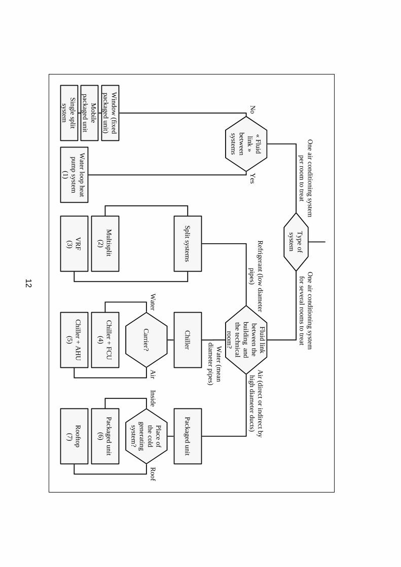
Conclusion This questionnaire must be completed for each cold generating system. The output of this questionnaire is a number (1 to 6). The association of that number and the letter (A to G) obtained by the other questionnaire (paragraph x) allows to determine the type of any installation. The diagram of the installation in question is then provided in appendix 3. The following diagram is a graphical translation of the previous 5 steps method.
12
Type of
system
Fluid link betw
een the building and the technical
room?
Multisplit
(2)
Chiller
Chiller
+ FC
U
(4)
Chiller
+ A
HU
(5)
Carrier?
Packaged unit
Place of the cold
generating system
?
Packaged unit(6)
Rooftop
(7)
Roof
InsideA
irW
ater
Air (direct or indirect by high diam
eter ducts)R
efrigerant (low diam
eter pipes)
Water (m
ean diam
eter pipes)
One air conditioning system
for several room
s to treatO
ne air conditioning system
per room to treat
«Fluid
link»
between
systemsW
ater loop heat pum
p system
(1) Yes
No
Split systems
Window
(fixed packaged unit)
Mobile
packaged unit
Single split system
VR
F(3)
13
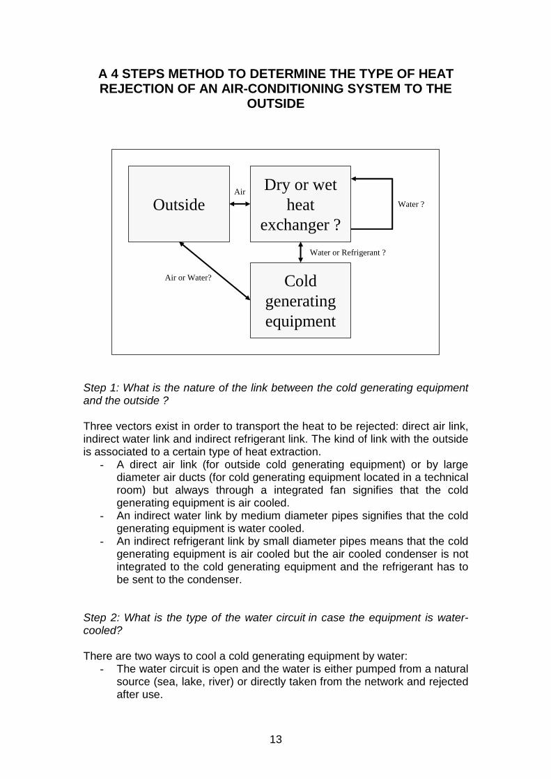
A 4 STEPS METHOD TO DETERMINE THE TYPE OF HEAT REJECTION OF AN AIR-CONDITIONING SYSTEM TO THE
OUTSIDE
Step 1: What is the nature of the link between the cold generating equipment and the outside ? Three vectors exist in order to transport the heat to be rejected: direct air link, indirect water link and indirect refrigerant link. The kind of link with the outside is associated to a certain type of heat extraction.
- A direct air link (for outside cold generating equipment) or by large diameter air ducts (for cold generating equipment located in a technical room) but always through a integrated fan signifies that the cold generating equipment is air cooled.
- An indirect water link by medium diameter pipes signifies that the cold generating equipment is water cooled.
- An indirect refrigerant link by small diameter pipes means that the cold generating equipment is air cooled but the air cooled condenser is not integrated to the cold generating equipment and the refrigerant has to be sent to the condenser.
Step 2: What is the type of the water circuit in case the equipment is water-cooled? There are two ways to cool a cold generating equipment by water:
- The water circuit is open and the water is either pumped from a natural source (sea, lake, river) or directly taken from the network and rejected after use.
Cold generating equipment
Dry or wet heat
exchanger ?Outside
Air or Water?
Water or Refrigerant ?
Air
Water ?
14
- The water circuit is closed and the water is recycled in a cooling tower (with limited water addition).
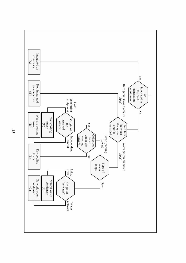
Step 3: Is there a collection basin at the bottom of the cooling tower ? Cooling towers can be « dry » or « wet ». Dry cooling towers are composed of a simple air/water heat exchanger and a fan so that there is no contact between the two fluids (water of the cold generating equipment and outside air). Wet cooling towers uses the latent energy of the water when vaporizing because there is a contact between water and air. In case of a wet cooling tower, the non-vaporized water is collected into a basin to be re-used after limited addition of fresh water. Step 4: Where does the sprayed water come from ? It is possible to distinguish two types of wet cooling towers: closed and open cooling towers. In the first type (closed), there is no contact between the primary water which cools the cold generating equipment and the outside air. There are two water circulations: the primary water passes in a heat exchanger on which secondary water is sprayed and air is ventilated. The secondary circuit needs back-up because water is partially vaporized. In the second type (open), the water which cools the cold generating equipment is in direct contact with the outside air. The water is sprayed on an exchange surface through which air is fanned. As the water vaporization is more important, the plume is also more important. Conclusion This diagram is a graphical translation of the previous 4 steps method. This questionnaire must be fulfill for each cold generating system. The output of this questionnaire is a letter (A to G). The association of that letter and the number (1 to 6) obtained by the other questionnaire allows to determine the type of any installation.
15
Close (cooling
tower)
Open
No
Yes
Yes
No
Netw
ork water
condenser(G
)
Natural w
ater condenser
(F)
Origin of
the water?
Water
network
Lake,
river
Type of w
ater loop?
Collection basin
under the cooling tow
er?
Wet-dry cooling
tower
(D)
Wet cooling tow
er (C
)
Origin of
the sprayed w
ater?
Cold
generating equipm
entIndependent
circuit
Dry cooling
tower
(E)
Integrated air condenser
(A)
Fan
integrated in the cold
generating equipm
ent
Fluid link
between
the system
and the outside?
Non integrated
air condenser (B
)
Refrigerant (low
diameter
pipes)W
ater (mean diam
eter pipes)
16
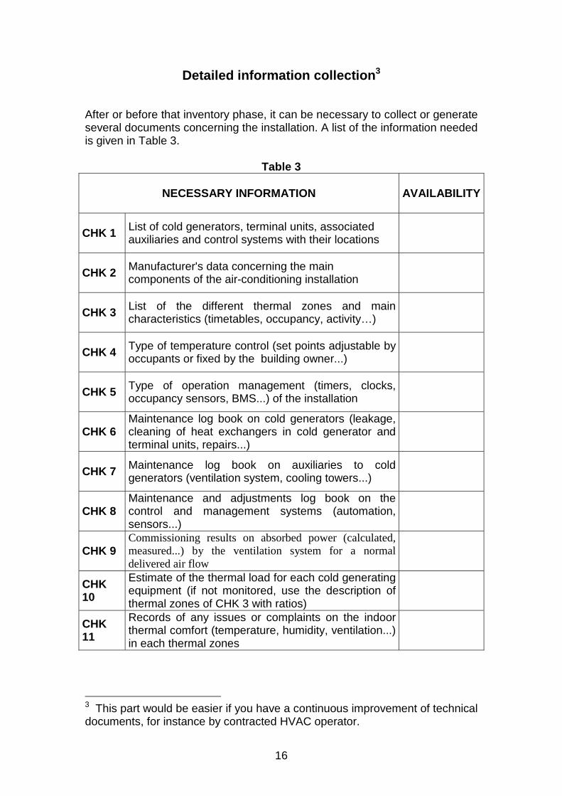
Detailed information collection3
After or before that inventory phase, it can be necessary to collect or generate several documents concerning the installation. A list of the information needed is given in Table 3.
Table 3
NECESSARY INFORMATION AVAILABILITY
CHK 1 List of cold generators, terminal units, associated auxiliaries and control systems with their locations
CHK 2 Manufacturer's data concerning the main components of the air-conditioning installation
CHK 3 List of the different thermal zones and main characteristics (timetables, occupancy, activity…)
CHK 4 Type of temperature control (set points adjustable by occupants or fixed by the building owner...)
CHK 5 Type of operation management (timers, clocks, occupancy sensors, BMS...) of the installation
CHK 6 Maintenance log book on cold generators (leakage, cleaning of heat exchangers in cold generator and terminal units, repairs...)
CHK 7 Maintenance log book on auxiliaries to cold generators (ventilation system, cooling towers...)
CHK 8 Maintenance and adjustments log book on the control and management systems (automation, sensors...)
CHK 9 Commissioning results on absorbed power (calculated, measured...) by the ventilation system for a normal delivered air flow
CHK 10
Estimate of the thermal load for each cold generating equipment (if not monitored, use the description of thermal zones of CHK 3 with ratios)
CHK 11
Records of any issues or complaints on the indoor thermal comfort (temperature, humidity, ventilation...) in each thermal zones
3 This part would be easier if you have a continuous improvement of technical documents, for instance by contracted HVAC operator.
17
CHK 12
Information about the BMS (managed equipments, set-points, operation, maintenance...)
CHK 13
Information about the monitoring station if any (managed equipments, parameters tracked, efficiency records...)
All these documents can be useful to determine the efficiency of the main components of the installation and how they work. An expert must examine the documents and verify that equipments are in place on the installation. It is however possible that all this information is not available. Nevertheless, it is possible to get details about some components of the air-conditioning system by carrying out a detailed walkthrough inspection of the building (and looking at the plates of the equipments) or talking with the maintenance manager or with subcontractors.
18
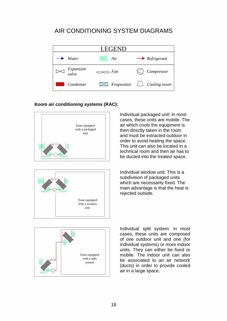
AIR CONDITIONING SYSTEM DIAGRAMS
Room air conditioning systems (RAC):
Water Air Refrigerant
Cooling towerCondenser Evaporator
Expansion valve Fan Compressor
LEGEND
Zone equipped with a packaged
unit
Individual packaged unit: in most cases, these units are mobile. The air which cools the equipment is then directly taken in the room and must be extracted outdoor in order to avoid heating the space. This unit can also be located in a technical room and then air has to be ducted into the treated space.
Zone equipped with a window
unit
Individual window unit: This is a subdivision of packaged units which are necessarily fixed. The main advantage is that the heat is rejected outside.
Zone equipped with a split
system
Individual split system: in most cases, these units are composed of one outdoor unit and one (for individual systems) or more indoor units. They can either be fixed or mobile. The indoor unit can also be associated to an air network (ducts) in order to provide cooled air in a large space.
19
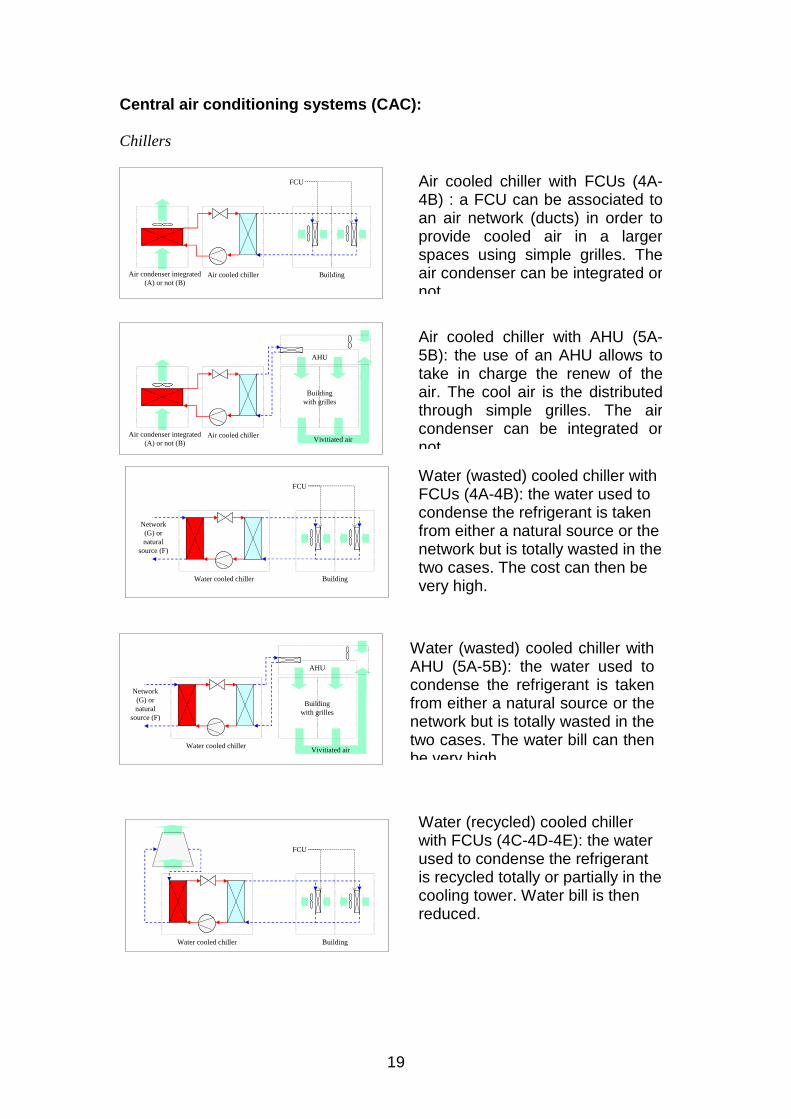
Central air conditioning systems (CAC): Chillers
Air cooled chiller with FCUs (4A-4B) : a FCU can be associated to an air network (ducts) in order to provide cooled air in a larger spaces using simple grilles. The air condenser can be integrated or not
Air cooled chiller with AHU (5A-5B): the use of an AHU allows to take in charge the renew of the air. The cool air is the distributed through simple grilles. The air condenser can be integrated or not
Water (wasted) cooled chiller with FCUs (4A-4B): the water used to condense the refrigerant is taken from either a natural source or the network but is totally wasted in the two cases. The cost can then be very high.
Water (wasted) cooled chiller withAHU (5A-5B): the water used tocondense the refrigerant is takenfrom either a natural source or thenetwork but is totally wasted in thetwo cases. The water bill can thenbe very high
Water (recycled) cooled chiller with FCUs (4C-4D-4E): the water used to condense the refrigerant is recycled totally or partially in the cooling tower. Water bill is then reduced.
Air cooled chiller Building
FCU
Air condenser integrated (A) or not (B)
Air cooled chiller
AHU
Building with grilles
Vivitiated airAir condenser integrated
(A) or not (B)
BuildingWater cooled chiller
Network (G) or natural
source (F)
FCU
BuildingWater cooled chiller
FCU
Water cooled chiller
Network (G) or natural
source (F)
Vivitiated air
AHU
Building with grilles
20
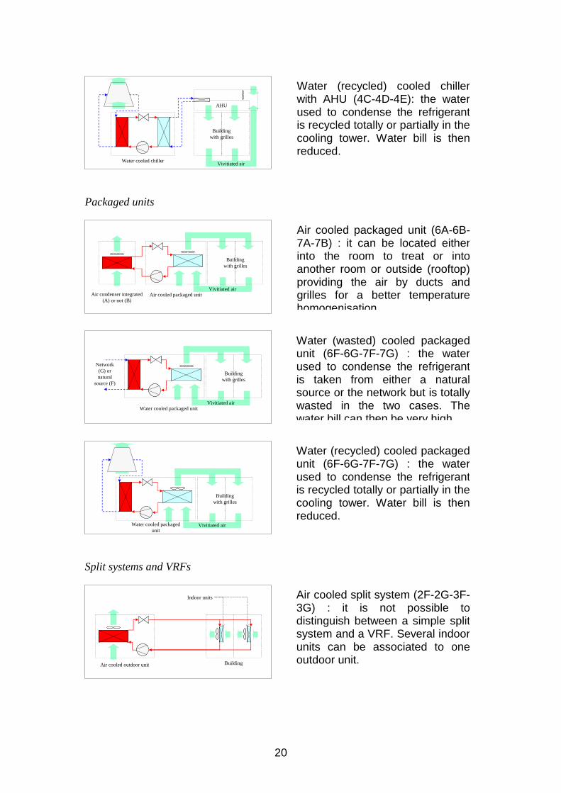
Packaged units
Split systems and VRFs
Water (recycled) cooled chiller with AHU (4C-4D-4E): the water used to condense the refrigerant is recycled totally or partially in the cooling tower. Water bill is then reduced.
Air cooled packaged unit (6A-6B-7A-7B) : it can be located either into the room to treat or into another room or outside (rooftop) providing the air by ducts and grilles for a better temperature homogenisation
Water (recycled) cooled packaged unit (6F-6G-7F-7G) : the water used to condense the refrigerant is recycled totally or partially in the cooling tower. Water bill is then reduced.
Water (wasted) cooled packaged unit (6F-6G-7F-7G) : the water used to condense the refrigerant is taken from either a natural source or the network but is totally wasted in the two cases. The water bill can then be very high
Air cooled split system (2F-2G-3F-3G) : it is not possible to distinguish between a simple split system and a VRF. Several indoor units can be associated to one outdoor unit.
Water cooled chillerVivitiated air
AHU
Building with grilles
Building with grilles
Vivitiated airAir cooled packaged unitAir condenser integrated
(A) or not (B)
Vivitiated air
Network (G) or natural
source (F)
Water cooled packaged unit
Building with grilles
Building with grilles
Vivitiated airWater cooled packaged unit
Air cooled outdoor unit Building
Indoor units
21
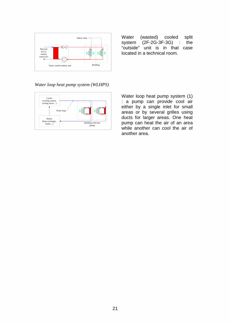
Water loop heat pump system (WLHPS)
Water (wasted) cooled split system (2F-2G-3F-3G) : the “outside” unit is in that case located in a technical room.
Water loop heat pump system (1) : a pump can provide cool air either by a single inlet for small areas or by several grilles using ducts for larger areas. One heat pump can heat the air of an area while another can cool the air of another area.
Water cooled outdoor unit Building
Indoor units
Network (G) or natural
source (F)
Building with heat pumps
Cooler (cooling system, cooling tower…)
Heater (heat exchanger,
boiler…)
Water loop
22
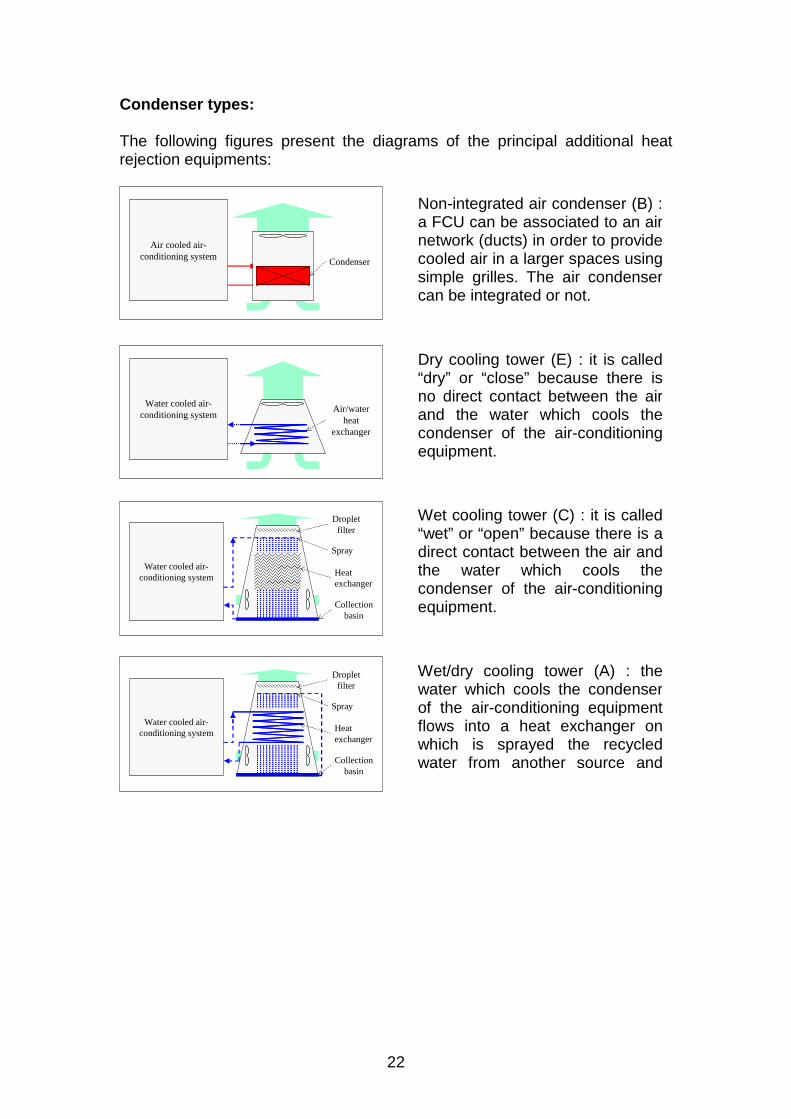
Condenser types: The following figures present the diagrams of the principal additional heat rejection equipments:
Non-integrated air condenser (B) : a FCU can be associated to an air network (ducts) in order to provide cooled air in a larger spaces using simple grilles. The air condenser can be integrated or not.
Dry cooling tower (E) : it is called “dry” or “close” because there is no direct contact between the air and the water which cools the condenser of the air-conditioning equipment.
Wet cooling tower (C) : it is called “wet” or “open” because there is a direct contact between the air and the water which cools the condenser of the air-conditioning equipment.
Wet/dry cooling tower (A) : the water which cools the condenser of the air-conditioning equipment flows into a heat exchanger on which is sprayed the recycled water from another source and
Condenser
Air cooled air-conditioning system
Water cooled air-conditioning system
Air/water heat
exchanger
Water cooled air-conditioning system
Droplet filter
Spray
Heat exchanger
Collection basin
Water cooled air-conditioning system
Droplet filter
Spray
Heat exchanger
Collection basin
23
CHECKING THERMAL COMFORT AND VENTILATION RATES
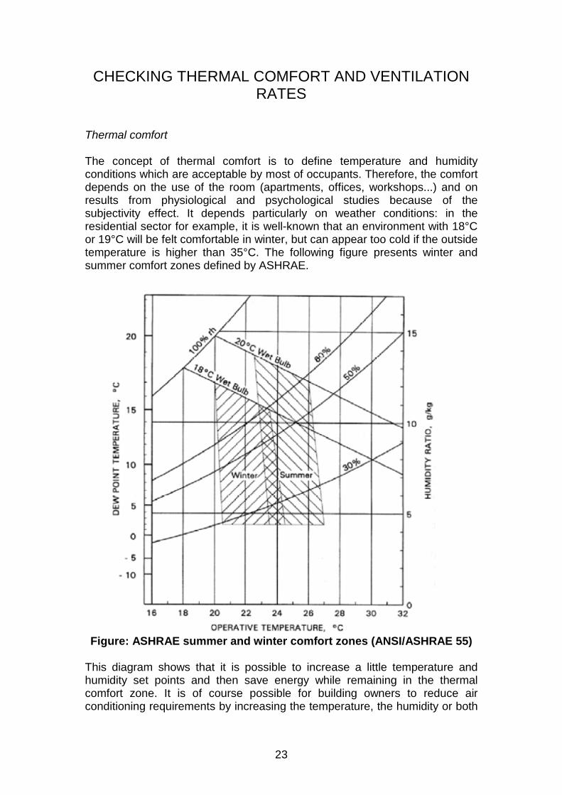
Thermal comfort The concept of thermal comfort is to define temperature and humidity conditions which are acceptable by most of occupants. Therefore, the comfort depends on the use of the room (apartments, offices, workshops...) and on results from physiological and psychological studies because of the subjectivity effect. It depends particularly on weather conditions: in the residential sector for example, it is well-known that an environment with 18°C or 19°C will be felt comfortable in winter, but can appear too cold if the outside temperature is higher than 35°C. The following figure presents winter and summer comfort zones defined by ASHRAE.
Figure: ASHRAE summer and winter comfort zones (ANSI/ASHRAE 55)
This diagram shows that it is possible to increase a little temperature and humidity set points and then save energy while remaining in the thermal comfort zone. It is of course possible for building owners to reduce air conditioning requirements by increasing the temperature, the humidity or both
24
and then to go out from the thermal comfort zone if occupants needs are lower. The change of the air It is necessary to distinguish the “fresh air flow” which is fixed by the automation, and the “blowing flow”, which must allow to extract the heat to ensure, either hygiene conditions (hospital, kitchens…) and/or of comfort conditions (habitat, tertiary sector), or the quality of products manufactured or conditioned (micro-electronic, pharmaceutical...). The two following tables (ASHRAE Standard 62-2001, Ventilation for acceptable indoor air quality, ASHRAE, 2001) gather the minimal new air flows for buildings with non-specific and specific pollutions.
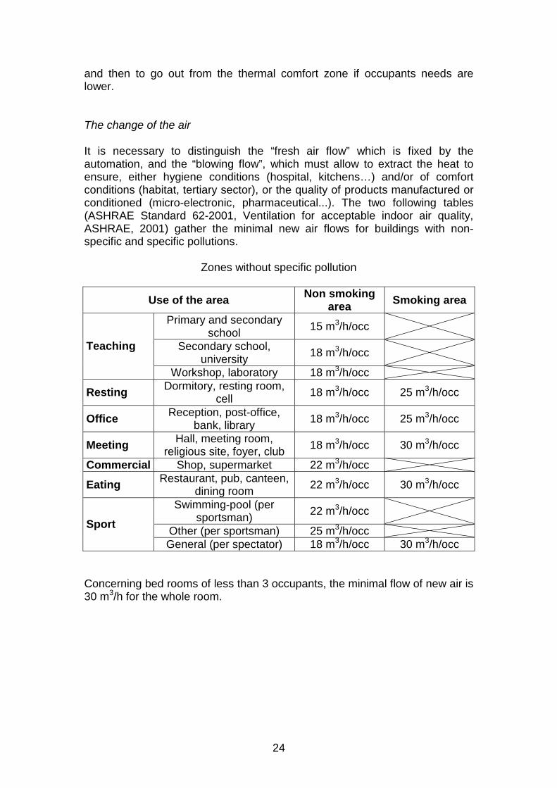
Zones without specific pollution
Use of the area Non smoking area Smoking area
Primary and secondary school 15 m3/h/occ
Secondary school, university 18 m3/h/occ Teaching
Workshop, laboratory 18 m3/h/occ
Resting Dormitory, resting room, cell 18 m3/h/occ 25 m3/h/occ
Office Reception, post-office, bank, library 18 m3/h/occ 25 m3/h/occ
Meeting Hall, meeting room, religious site, foyer, club 18 m3/h/occ 30 m3/h/occ
Commercial Shop, supermarket 22 m3/h/occ
Eating Restaurant, pub, canteen, dining room 22 m3/h/occ 30 m3/h/occ
Swimming-pool (per sportsman) 22 m3/h/occ
Other (per sportsman) 25 m3/h/occ Sport
General (per spectator) 18 m3/h/occ 30 m3/h/occ Concerning bed rooms of less than 3 occupants, the minimal flow of new air is 30 m3/h for the whole room.
25
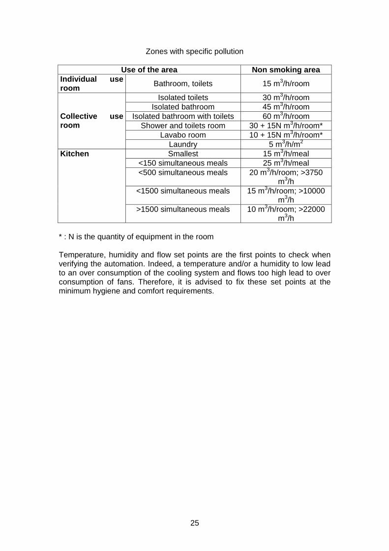
Zones with specific pollution
Use of the area Non smoking area Individual use room Bathroom, toilets 15 m3/h/room
Isolated toilets 30 m3/h/room Isolated bathroom 45 m3/h/room
Isolated bathroom with toilets 60 m3/h/room Shower and toilets room 30 + 15N m3/h/room*
Lavabo room 10 + 15N m3/h/room*
Collective use room
Laundry 5 m3/h/m2 Smallest 15 m3/h/meal
<150 simultaneous meals 25 m3/h/meal <500 simultaneous meals 20 m3/h/room; >3750
m3/h <1500 simultaneous meals 15 m3/h/room; >10000
m3/h
Kitchen
>1500 simultaneous meals 10 m3/h/room; >22000 m3/h
* : N is the quantity of equipment in the room Temperature, humidity and flow set points are the first points to check when verifying the automation. Indeed, a temperature and/or a humidity to low lead to an over consumption of the cooling system and flows too high lead to over consumption of fans. Therefore, it is advised to fix these set points at the minimum hygiene and comfort requirements.