Audio in eCall and Cluster - TI training and training ... FAE Summit... · Audio in eCall and...
45
Audio in eCall and Cluster 1 Clancy Soehren – MSA Applications FAE Summit 2016
Transcript of Audio in eCall and Cluster - TI training and training ... FAE Summit... · Audio in eCall and...

Audio in eCall and Cluster
1
Clancy Soehren – MSA Applications
FAE Summit 2016

Agenda
• Audio Architecture
• Audio Quality
• Diagnostics and Protection
• Efficiency
• EMI/EMC
2

Audio Architecture
3

Cluster Mid-Range Hybrid
4

5
Vbat
Reverse
Battery
Protection
Voltage
Conditioning
Module
Gas
Gauge
Battery
Charger
3.6V-3.9V
~3.6V/cell
Or Power Path
LDO
LDO
OVP
Protector
eCall with Li-Ion Battery 1.4.2.1.1 Class D Amp supports Off-Battery Protection, 1s
Pre
Boost
Class D Amp OR
to CAN Bus CAN CAN
ES
D
ES
D
Connectivity
Module
Class D
Amplifier
Wireless
Speaker
Microphone
MCU
eCall Trigger
Manual Trigger
ADC
Signal Path 4V
3.3V
5V
8-Vbat
I2S/
Analog
SVS or
Comparator
DAC
Audio
Codec
Bias
8-9V
3.3V
Amp
5V
ES
D
ES
D
ES
D
S2B
LIN
Vbat
UART
RS
23
2
Off Battery
Buck
4V
5V
3.3V
MCU
MCU
OR

Audio Signal Path
6
Amp ADC Wireless Transmission
DAC Amp
Audio Signal Source Transmission/
Processing Playback
Synthesized Digital
Signal Storage Medium

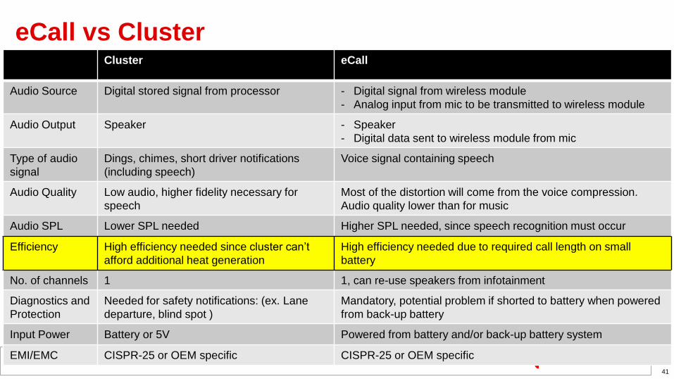
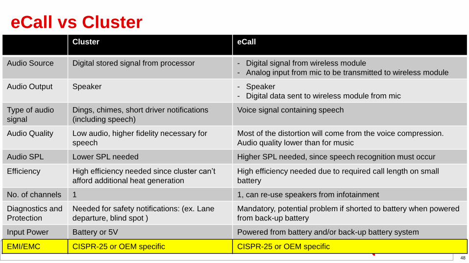
eCall vs Cluster
10
Cluster eCall
Audio Source Digital stored signal from processor - Digital signal from wireless module
- Analog input from mic to be transmitted to wireless module
Audio Output Speaker - Speaker
- Digital data sent to wireless module from mic
Type of audio
signal
Dings, chimes, short driver notifications
(including speech)
Voice signal containing speech
Audio Quality Low audio, higher fidelity necessary for
speech
Most of the distortion will come from the voice compression.
Audio quality lower than for music
Audio SPL Lower SPL needed Higher SPL needed, since speech recognition must occur
Efficiency High efficiency needed since cluster can’t
afford additional heat generation
High efficiency needed due to required call length on small
battery
No. of channels 1 1, can re-use speakers from infotainment
Diagnostics and
Protection
Needed for safety notifications: (ex. Lane
departure, blind spot )
Mandatory, potential problem if shorted to battery when powered
from back-up battery
Input Power Battery or 5V Powered from battery and/or back-up battery system
EMI/EMC CISPR-25 or OEM specific CISPR-25 or OEM specific

Audio Quality
11

Important Parameters for Audio Quality
12
• ADC/DAC/CODEC:
– THD+N
– Frequency Response
– SNR of signal chain
• Dynamic range
• Amplifier:
– THD+N
– Output Power
– PSRR
– Pop and Click
– Frequency response
• Output filter
• Speaker:
– SPL – Sound Pressure Level, function of acoustic power from the speaker, (dB/W at 1m)

Clipping and THDN
13
THDN < 1%
THDN ~= 10%
Signal clipped
PVCC
PVCC
OUTP
OUTP
OUTN
OUTN

Harmonic Content of Sounds
14
Trumpet – A Note Clarinet – A Note
Fundamental = 440 Hz Fundamental = 440 Hz

THD+N Examples
15
clipping

THD+N – What Causes Distortion?
16
1% - 5%
THDN
Amp ADC Transmission DAC Amp
0.01% –0.1%
THDN
Compressed
to 48kHz
bandwidth

Maximum Output Power vs PVCC to Avoid Clipping
17
0
5
10
15
20
25
30
35
40
0 5 10 15 20
Ou
tpu
t P
ow
er
(W)
PVCC(V)
Max Unclipped Power for 4 ohm Load
𝑉ℎ𝑒𝑎𝑑𝑟𝑜𝑜𝑚 =𝑅𝑑𝑠𝑜𝑛
2 ∗ 𝑅𝑑𝑠𝑜𝑛 + 𝑅𝐿∗ 𝑃𝑉𝐶𝐶
Po =VRMS2
RL=Vpeak2
2 ∗ RL
Due to clipping, the maximum
output power is limited by PVCC.

PSRR – Power Supply Rejection Ratio
19
• A measure of how much of the noise from
the power supply line will feed through to the
output of the audio amplifier

20
Output Filter Frequency Response
15 µH
15 µH
2.2 µF
2.2 µF
• Simple LC reconstruction filter
• fc = 27.7kHz
Design Equations:

SNR – Signal to Noise Ratio
• SNR is the ratio of the wanted signal to the background noise.
21
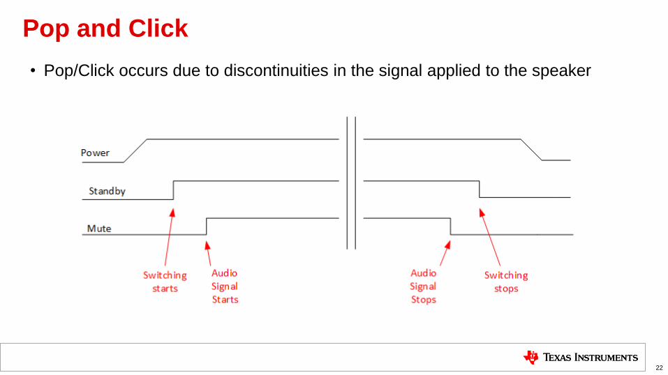
Pop and Click
• Pop/Click occurs due to discontinuities in the signal applied to the speaker
22

SPL – Sound Pressure Level
• Sound Pressure Level: The deviation from the ambient pressure level caused by
a sound wave.
23
DAC Amp
Power
delivered to
speaker
Sound waves,
measured in
SPL

eCall vs Cluster
24
Cluster eCall
Audio Source Digital stored signal from processor - Digital signal from wireless module
- Analog input from mic to be transmitted to wireless module
Audio Output Speaker - Speaker
- Digital data sent to wireless module from mic
Type of audio
signal
Dings, chimes, short driver notifications
(including speech)
Voice signal containing speech
Audio Quality Low audio, higher fidelity necessary for
speech
Most of the distortion will come from the voice compression.
Audio quality lower than for music
Audio SPL Lower SPL needed Higher SPL needed, since speech recognition must occur
Efficiency High efficiency needed since cluster can’t
afford additional heat generation
High efficiency needed due to required call length on small
battery
No. of channels 1 1, can re-use speakers from infotainment
Diagnostics and
Protection
Needed for safety notifications: (ex. Lane
departure, blind spot )
Mandatory, potential problem if shorted to battery when powered
from back-up battery
Input Power Battery or 5V Powered from battery and/or back-up battery system
EMI/EMC CISPR-25 or OEM specific CISPR-25 or OEM specific

Diagnostics and Protection
25

Load Diagnostic Requirements
• Four types of connection problems:
– Short to Battery
– Short to Ground
– Shorted load
– Open load
26
DAC Amp
Long wires

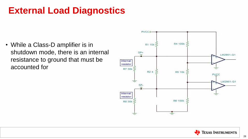
External Load Diagnostics
• Two comparators and a resistive network can be used to provide external load
diagnostics
27
FAULT CONDITIONS LEDs
No fault Both LEDs off
Open load Both LEDs on
Short to PVCC LED on SP+ on, LED on SP- off
Short to GND LED on SP+ off, LED on SP- on
External Load Diagnostics
• While a Class-D amplifier is in
shutdown mode, there is an internal
resistance to ground that must be
accounted for
28

Internal vs External Load Diagnostics Cost Estimate
29
Component 1k Cost:
Comparator
(2 per channel)
$0.12
2 GPIO channels on
MCU
Dependent on MCU
PCB space Affects system cost
TAS5411-Q1: Class-D amplifier with integrated load diagnostics

Short to Battery

Adding the Schottky Diode

eCall vs Cluster
32
Cluster eCall
Audio Source Digital stored signal from processor - Digital signal from wireless module
- Analog input from mic to be transmitted to wireless module
Audio Output Speaker - Speaker
- Digital data sent to wireless module from mic
Type of audio
signal
Dings, chimes, short driver notifications
(including speech)
Voice signal containing speech
Audio Quality Low audio, higher fidelity necessary for
speech
Most of the distortion will come from the voice compression.
Audio quality lower than for music
Audio SPL Lower SPL needed Higher SPL needed, since speech recognition must occur
Efficiency High efficiency needed since cluster can’t
afford additional heat generation
High efficiency needed due to required call length on small
battery
No. of channels 1 1, can re-use speakers from infotainment
Diagnostics and
Protection
Needed for safety notifications: (ex. Lane
departure, blind spot )
Mandatory, potential problem if shorted to battery when powered
from back-up battery
Input Power Battery or 5V Powered from battery and/or back-up battery system
EMI/EMC CISPR-25 or OEM specific CISPR-25 or OEM specific

Efficiency
33

Amplifier Classes
• Class A – The output stage is always conducting and is very inefficient
• Class B – The output stage is conducting on ½ of the signal and if more efficient that class A, but with severe
crossover distortion.
• Class AB – A hybrid of class A and class B. The output stage is conducting on a little more than ½ of the signal
to eliminate the crossover distortion. Less efficient than Class B.
• Class C – Typical of RF amplifiers and will not be discussed.
• Class D – The audio signal is modulated with a higher frequency so the output stage can be operated very
efficiently.
• Class G and H – These are not amplifier types but power supply types that provide power to audio amplifiers and will
not be discussed.
34
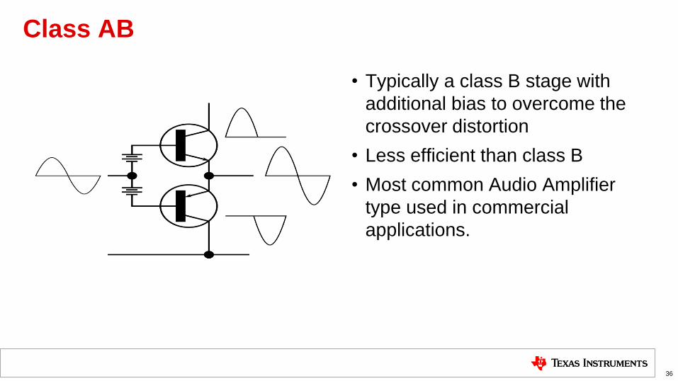
Class AB
• Typically a class B stage with
additional bias to overcome the
crossover distortion
• Less efficient than class B
• Most common Audio Amplifier
type used in commercial
applications.
36

Class D
• Modulated with a high frequency signal. Typically to generate a pulse width modulated signal (PWM)
• The output transistors switch “on” to saturation and “off” to complete cut off.
• Voltage across the transistor is minimal during current flow for high efficiency.
• Typically 90% in modern PWM Class D amplifiers
• High frequency switching can be a challenge for EMC.
37

Thermal Image of PCB with Class-AB Amp
38
ST Power Amplifier. PVDD=14.4Vdc, 4 ohm load, 1W output

Thermal Image of PCB with Class-D Amp
39
TI TAS5421-Q1 Power Amplifier. PVDD=14.4Vdc, 4 ohm load, 1W output
eCall vs Cluster
41
Cluster eCall
Audio Source Digital stored signal from processor - Digital signal from wireless module
- Analog input from mic to be transmitted to wireless module
Audio Output Speaker - Speaker
- Digital data sent to wireless module from mic
Type of audio
signal
Dings, chimes, short driver notifications
(including speech)
Voice signal containing speech
Audio Quality Low audio, higher fidelity necessary for
speech
Most of the distortion will come from the voice compression.
Audio quality lower than for music
Audio SPL Lower SPL needed Higher SPL needed, since speech recognition must occur
Efficiency High efficiency needed since cluster can’t
afford additional heat generation
High efficiency needed due to required call length on small
battery
No. of channels 1 1, can re-use speakers from infotainment
Diagnostics and
Protection
Needed for safety notifications: (ex. Lane
departure, blind spot )
Mandatory, potential problem if shorted to battery when powered
from back-up battery
Input Power Battery or 5V Powered from battery and/or back-up battery system
EMI/EMC CISPR-25 or OEM specific CISPR-25 or OEM specific

Designing for EMI/EMC
42

45
Layout Example
Bypass caps placed
close to PVDD Switching nodes
must be kept small
Return path through caps
of LC filter must provide
clear path to ground.
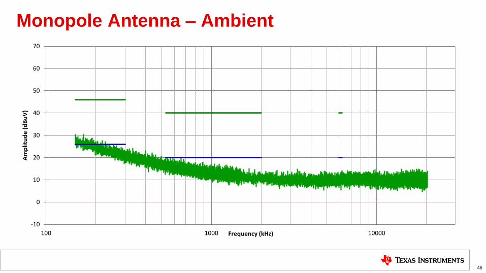
Monopole Antenna – Ambient
46
-10
0
10
20
30
40
50
60
70
100 1000 10000
Am
plit
ud
e (
dB
uV
)
Frequency (kHz)

Monopole Antenna – 500kHz PWM Switching Frequency
47
-10
0
10
20
30
40
50
60
70
100 1000 10000
Am
plit
ud
e (
dB
uV
)
Frequency (kHz)
eCall vs Cluster
48
Cluster eCall
Audio Source Digital stored signal from processor - Digital signal from wireless module
- Analog input from mic to be transmitted to wireless module
Audio Output Speaker - Speaker
- Digital data sent to wireless module from mic
Type of audio
signal
Dings, chimes, short driver notifications
(including speech)
Voice signal containing speech
Audio Quality Low audio, higher fidelity necessary for
speech
Most of the distortion will come from the voice compression.
Audio quality lower than for music
Audio SPL Lower SPL needed Higher SPL needed, since speech recognition must occur
Efficiency High efficiency needed since cluster can’t
afford additional heat generation
High efficiency needed due to required call length on small
battery
No. of channels 1 1, can re-use speakers from infotainment
Diagnostics and
Protection
Needed for safety notifications: (ex. Lane
departure, blind spot )
Mandatory, potential problem if shorted to battery when powered
from back-up battery
Input Power Battery or 5V Powered from battery and/or back-up battery system
EMI/EMC CISPR-25 or OEM specific CISPR-25 or OEM specific

Collateral
49

Customer collateral
50
The following information is available for you to send for customers
Content title Content type Link to content or more details
TIDA-00724 eCall Audio
Subsystem
TI Design for audio in eCall. Uses
the TAS5411-Q1 and
TLV320AIC3104-Q1
http://www.ti.com/tool/tida-00724
External Load
Diagnostics Application
Note
Application Note for external load
diagnostics. Uses the TPA3111D1-
Q1.
4Q 2016
Class-D Amplifier Short
to Battery Protection
Application note describing short to
battery protection options. Uses the
TPA3111D1-Q1.
4Q 2016
TI Information – Selective Disclosure

• Integrated load dump protection to withstand 40V
voltage spikes
• Wide input voltage range: 4.5V - 18V
• Integrated diagnostics for output pin to pin shorts,
short to ground, short to battery, and open load
• Up to 8W of output power through a 4 ohm speaker
• Dual channel TLV320AIC3104-Q1 allows for input
from a microphone and audio data from a wireless
module to facilitate a 2-way call
• Tested for radiated emissions according to CISPR-
25
• Codec has configurable options for gain, digital
audio format, PLL, and filtering
• Automotive Emergency Call (eCall)
• Telematics + eCall
• Gateway + eCall
• The integrated load-dump protection reduces external
voltage clamp cost and size
• Onboard load diagnostics report the status of the speaker
through I2C, which reduces external components needed for
diagnostic coverage
• TLV320AIC3104-Q1 + TAS5411-Q1 combo allows for:
• reduced power consumption
• reduced heat
• reduced peak currents in the electrical system
• Loud, clear audio in an unpredictable emergency
environment
• Ability to use an additional output from the codec for the
head unit or other car audio needs
Audio Emergency Call (eCall) Subsystem Reference Design
Features Benefits
Applications
http://www.ti.com/tool/tida-00724

Questions
52