
AUDIO DOOR ENTRY SYSTEM - Timeguard DOOR ENTRY SYSTEM Model: DCA1 Single Channel DCA2 Twin Channel...
12
INSTALLATION & OPERATING INSTRUCTIONS AUDIO DOOR ENTRY SYSTEM Model: DCA1 Single Channel DCA2 Twin Channel DCA1 DCA2 DCA1/2
Transcript of AUDIO DOOR ENTRY SYSTEM - Timeguard DOOR ENTRY SYSTEM Model: DCA1 Single Channel DCA2 Twin Channel...

INSTA
LLATIO
N &
OPER
ATIN
G IN
STRU
CTION
S
AUDIO DOOR ENTRY SYSTEMModel: DCA1 Single Channel
DCA2 Twin Channel
DCA1DCA2
DCA1/2
DCA1_DCA2_Instructs_1.4.indd 1DCA1_DCA2_Instructs_1.4.indd 1 30/1/07 11:00:25 am30/1/07 11:00:25 am

17
3
10
5
2
1
4
98
1. IntroductionThe DCA1/DCA2 Door Entry System enhances entry security by enabling the user to recognise the potential entrant by audible means before opening the door.
An electric door catch (not supplied) is available as an optional extra for the DCA1/DCA2 to make the door opening automatic.
The DCA2 external intercom has the ability to call separately located internal intercoms for two individual dwellings with a common entrance. The DCA1 calls one.
Connecting cables between component parts are all 2 core, so existing bell fl ex can be used to connect the internal and external units if desired.
2. OverviewIf operation with an electric door catch is required then part DCLR is a fail (power off) secure catch available from Timeguard.
Fig 1Component parts of Single Channel system.
1. External intercom (1 channel shown)
2. Internal intercom
3. Mains adaptor
4. 15m of 2 core connecting cable
5. Cable terminals
7. Ring button
8. Ringtone volume adjust (2 position switch)
9. Door open button
10. Mains adaptor low voltage plug
DCA1_DCA2_Instructs_1.4.indd 2DCA1_DCA2_Instructs_1.4.indd 2 30/1/07 11:00:33 am30/1/07 11:00:33 am
2
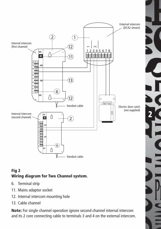
Fig 2Wiring diagram for Two Channel system.
6. Terminal strip
11. Mains adaptor socket
12. Internal intercom mounting hole
13. Cable channel
Note: For single channel operation ignore second channel internal intercom and its 2 core connecting cable to terminals 3 and 4 on the external intercom.
Internal intercom(fi rst channel)
Internal intercom(second channel)
External intercom(DCA2 shown)
Electric door catch(not supplied)
Handset cable
Handset cable
DCA1_DCA2_Instructs_1.4.indd 3DCA1_DCA2_Instructs_1.4.indd 3 30/1/07 11:00:34 am30/1/07 11:00:34 am

3
50cm
165cm
75º
165cm
3. Selecting intercom sites and cabling3.1 Intercom sitesThe internal intercom should be located at a convenient position for all potential users at the height indicated in fi g 3a and at a maximum distance of 70m from the external intercom. If all the users are signifi cantly above or below average height then a different mounting height may be considered appropriate.
The external intercom should be sited in an area away from driving rain and surface water, out of direct sunlight as far as possible and protected by the minimum of an open porch in a position readily accessible to potential entrants. It should be mounted at the height indicated in fi g 3b.
Fig 3aInternal intercom mounting height
Fig 3bExternal intercom mounting
height and coverage
DCA1_DCA2_Instructs_1.4.indd 4DCA1_DCA2_Instructs_1.4.indd 4 30/1/07 11:00:34 am30/1/07 11:00:34 am

4
3.2 CablingConnection between the internal and external intercoms is by 2 core cable and must be no more than 70 m long. Two core (13 x 0.2) bell fl ex is suitable.
A 15m length (2 lengths for DCA2) of 2 core cable is supplied with the kit and existing bell cable runs can be made use of.
The cable run should be kept at least 100mm away from mains cables to avoid interference.
A second relatively short 2 core cable (13/0.2 bell fl ex) will be required between the external intercom and the door catch (if used).
A further 2 core cable (13/0.2 bell fl ex) will be required (if extension beyond 15m is necessary) between the external intercom and the second internal intercom for the DCA2.
4. Fixing Intercoms4.1 External intercomImportant: To give the best possible waterproofi ng and appearance we recommend taking the wiring through the exterior wall directly behind the external intercom so that the cabling will feed directly through the back box wiring slot. If the surface to be fi xed to is not even (e.g. pebbledash or brickwork with raised pointing) we recommend the use of at least 10mm (3/8") thick marine ply as a mounting plate between the wall and the back box to prevent its distortion and loss of waterproofi ng.
DCA1_DCA2_Instructs_1.4.indd 5DCA1_DCA2_Instructs_1.4.indd 5 30/1/07 11:00:35 am30/1/07 11:00:35 am
5
xY
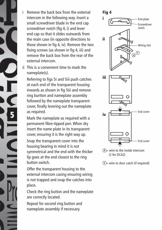
i Remove the back box from the external intercom in the following way. Insert a small screwdriver blade in the end cap screwdriver notch (fi g 4, i) and lever end cap so that it slides outwards from the main case (in opposite directions to those shown in fi g 4, iv). Remove the two fi xing screws (as shown in fi g 4, iii) and remove the back box from the rear of the external intercom.
ii This is a convenient time to mark the nameplate(s).
Referring to fi gs 5i and 5iii push catches at each end of the transparent housing inwards as shown in fi g 5iii and remove ring burtton and nameplate assembly followed by the nameplate transparent cover, fi nally levering out the nameplate as required.
Mark the nameplate as required with a permanent fi bre-tipped pen. When dry insert the name plate in its transparent cover, ensuring it is the right way up.
Snap the transparent cover into the housing bearing in mind it is not symmetrical and the end with the thicker lip goes at the end closest to the ring button switch.
Offer the transparent housing to the external intercom casing ensuring wiring is not trapped and snap the catches into place.
Check the ring button and the nameplate are correctly located.
Repeat for second ring button and nameplate assembly if necessary.
Fig 4i
X = wire to the inside intercom (2 for DCA2) Y = wire to door catch (if required)
End plate
Screwdriver notch
ii
iii
ivEnd cover
End cover
Wiring slot
DCA1_DCA2_Instructs_1.4.indd 6DCA1_DCA2_Instructs_1.4.indd 6 30/1/07 11:00:35 am30/1/07 11:00:35 am

6
1 2 3 4 5 6 7 8
Fig 5i – Rear access to nameplates (DCA2 shown)
Fig 5ii – Side view of length of nameplate
Fig 5iii – Transparent housing
Ring button switch
CatchTransparent housing
Push catch inwardsPCB
This (thicker) end goes closest to ring button switch
Catch
Ring button switch
Transparent housing
Catch
DCA1_DCA2_Instructs_1.4.indd 7DCA1_DCA2_Instructs_1.4.indd 7 30/1/07 11:00:35 am30/1/07 11:00:35 am

7
iii Offer the back box up to the required position on the wall (refer to section 3.1). Feed the cables through the wiring slot in the back box (see fi g 4, ii). Mark the positions of the two fi xing screws (No. 8 roundhead) using the back box as a template (see fi g 4, ii). Remove the back box, drill and, if necessary plug holes. Feed the cables through the wiring slot. Fix the back box to the wall.
iv Make the necessary wire terminations (see fi g 2) and offer the external intercom up to the back box. Tighten the fi xing screws as indicated (fi g 4, iii).
v Slide the two end covers inwards as shown until fully home (see fi g 4, iv).
4.2 Internal intercomChoose a position which can be reached easily by all potential users. If one person usually in one location will be the main user it may be considered appropriate to locate the internal intercom within reach of that person.
Mark out two holes suitable for No. 8 roundhead screws 164mm vertically apart at the required location on the wall (refer to section 3.1 and fi g 2). Drill and plug the holes if necessary then screw the screws home leaving 5mm of the shank exposed (see fi g 6) to enable keyhole fi xing points to slide behind the screws.
Connect the two core lead from the external intercom according to fi g 2. Plug the mains adaptor low voltage plug (see fi g 1) into the mains adaptor socket (see fi g 2). Arrange the two cables in the cable channel on the back of the internal intercom. Finally locate the internal intercom mounting holes on the two fi xing screws, and slide the intercom downwards.
Fig 6
Wall surface
5mm
DCA1_DCA2_Instructs_1.4.indd 8DCA1_DCA2_Instructs_1.4.indd 8 30/1/07 11:00:36 am30/1/07 11:00:36 am
8
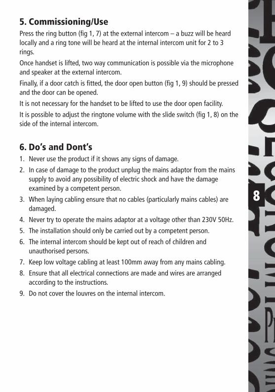
5. Commissioning/UsePress the ring button (fi g 1, 7) at the external intercom – a buzz will be heard locally and a ring tone will be heard at the internal intercom unit for 2 to 3 rings.
Once handset is lifted, two way communication is possible via the microphone and speaker at the external intercom.
Finally, if a door catch is fi tted, the door open button (fi g 1, 9) should be pressed and the door can be opened.
It is not necessary for the handset to be lifted to use the door open facility.
It is possible to adjust the ringtone volume with the slide switch (fi g 1, 8) on the side of the internal intercom.
6. Do’s and Dont’s1. Never use the product if it shows any signs of damage.
2. In case of damage to the product unplug the mains adaptor from the mains supply to avoid any possibility of electric shock and have the damage examined by a competent person.
3. When laying cabling ensure that no cables (particularly mains cables) are damaged.
4. Never try to operate the mains adaptor at a voltage other than 230V 50Hz.
5. The installation should only be carried out by a competent person.
6. The internal intercom should be kept out of reach of children and unauthorised persons.
7. Keep low voltage cabling at least 100mm away from any mains cabling.
8. Ensure that all electrical connections are made and wires are arranged according to the instructions.
9. Do not cover the louvres on the internal intercom.
DCA1_DCA2_Instructs_1.4.indd 9DCA1_DCA2_Instructs_1.4.indd 9 30/1/07 11:00:36 am30/1/07 11:00:36 am

9
7. TroubleshootingNo Audio Check cable between internal and external intercoms
is connected correctly.
Check that there are no breaks or damage to the interconnecting two core cable.
Check that the mains adaptor is plugged in and switched on.
Door catch not working Check cable between external intercom and door catch for breaks or damage.
Check that terminations are correctly made at each end of the above cable.
Check that the mains adaptor is plugged in and switched on.
8. CleaningUnplug mains adaptor before cleaning product.
Clean internal and external intercoms with a damp cloth only – no cleaning agents.
Remove dust deposits from the louvres on the internal intercom with a soft brush or vacuum cleaner.
(if fi tted)
DCA1_DCA2_Instructs_1.4.indd 10DCA1_DCA2_Instructs_1.4.indd 10 30/1/07 11:00:36 am30/1/07 11:00:36 am

10
9. Specifi cationsMains adaptor: 230V 50Hz/15V, 1A
Maximum interconnect length between internal and external intercoms: 70m (13/0.2 bell fl ex)
Power consuption Standby: 3W
In operation: 10W
Operating temperature: -10°C to +50°C
Ringtone volume: 80dBA at 0.3m maximum
(adjustable by 2 position slide switch)
Door catch: Max 12V DC 1A
3 Year GuaranteeIn the unlikely event of this product becoming faulty due to defective material or manufacture within 3 years of the date of purchase, please return it to your supplier in the fi rst year with proof of purchase and it will be replaced free of charge. For years 2 and 3 or any diffi culty in the fi rst year telephone the helpline on 020 8450 0515.
RecyclingWhen service life is over please consult your local authority regarding method of disposal.
DCA1_DCA2_Instructs_1.4.indd 11DCA1_DCA2_Instructs_1.4.indd 11 30/1/07 11:00:36 am30/1/07 11:00:36 am

11 For a product brochure please contact:
Timeguard Ltd.Victory Park, 400 Edgware Road,
London NW2 6ND020-8452-1112
or email [email protected]
HELPLINE
020-8450-0515
67-058-232
DCA1_DCA2_Instructs_1.4.indd 12DCA1_DCA2_Instructs_1.4.indd 12 30/1/07 11:00:36 am30/1/07 11:00:36 am


![DOOR TO DOOR COLLECTION OF MSW IN CATALONIA · DOOR TO DOOR COLLECTION OF MSW IN CATALONIA ... Separate Collection Door to Door in Catalonia [1] DtD abandoned Municipalities DtD Door](https://static.fdocuments.in/doc/165x107/5fb98d88d1680979b16ece80/door-to-door-collection-of-msw-in-catalonia-door-to-door-collection-of-msw-in-catalonia.jpg)