Attitude and Position Control of Quadrotors: Design ...
75
Attitude and Position Control of Quadrotors: Design, Implementation and Experimental Evaluation By Maziar Mardan A Thesis submitted to the Faculty of Graduate Studies in partial fulfillment of the requirements for the degree of Master of Science Department of Mechanical and Manufacturing Engineering Faculty of Engineering University of Manitoba Winnipeg, Manitoba, Canada March 2016 Copyright © 2016, Maziar Mardan
Transcript of Attitude and Position Control of Quadrotors: Design ...

Attitude and Position Control of Quadrotors:
Design, Implementation and Experimental Evaluation
By
Maziar Mardan
A Thesis submitted to the Faculty of Graduate Studies in
partial fulfillment of the requirements for the degree of
Master of Science
Department of Mechanical and Manufacturing Engineering
Faculty of Engineering
University of Manitoba
Winnipeg, Manitoba, Canada
March 2016
Copyright ©
2016, Maziar Mardan
i
Abstract
The performance of a quadrotor can be significantly disturbed in presence of wind. Current
controller designs have often neglected external disturbances, or otherwise, suggested complex
algorithms for wind disturbance estimation or complex nonlinear control techniques which are
challenging to be implemented. In this thesis, a simple-to-implement linear fixed gain attitude
controller is proposed to render a robust and accurate trajectory tracking in the presence of
disturbance and model uncertainties. The attitude controller design is based on Quantitative
Feedback Theory (QFT). QFT provides a graphical controller design procedure, in which the
design criteria are graphically illustrated for the whole range of plant uncertainties. As a result, it
is feasible to reach a trade-off between controller performance and complexity. Further, a fuzzy
logic controller is employed to provide satisfactory position trajectory tracking for the quadrotor.
In order to test the performance of the controllers, a set of simulation studies have been done.
The simulation is based on the nonlinear equations of motion for the quadrotor and is
implemented under Simulink®/MATLAB®. Moreover, the performances of the controllers, in
terms of disturbance rejection and trajectory tracking are experimentally studied. Finally, a flight
scenario is performed to compare the performances of the designed QFT-Fuzzy control scheme
with the ArduCopter, an open-source autopilot for commercially-available multi-rotors. Based on
the experiments, the mean squared reference tracking error of the quadrotor under the proposed
control scheme is decreased by 50%.

ii
Acknowledgments
First and foremost, I would like to thank my supervisor Dr. Nariman Sepehri without whom the
current research and its contributions would be impossible. His expertise and knowledge
immensely assisted me throughout my Master’s program. I greatly appreciate his guidance and
support. It will always be a privilege for me to work under his supervision.
I would like to thank all the staff at University of Manitoba for providing me with this
opportunity. I would like to thank PhD candidate, Vikram Banthia and Mr. Ali Maddahi for their
support during my research.
I would like to thank my parents, Nassim and Hamid, and my sister, Maryam, for their
unconditional support and encouragements during my studies. I wish to thank you for all of the
efforts and sacrifices you have made to help me to pursue my dreams.
Last but not least, I would like to thank all friends and colleagues who were there for me
whenever I needed a helping hand. It would be tremendously more difficult for me without their
kindness and support.
iii
Table of contents
Abstract ............................................................................................................................................ i
Acknowledgments........................................................................................................................... ii
Table of contents ............................................................................................................................ iii
List of figures .................................................................................................................................. v
List of tables .................................................................................................................................... x
Introduction ..................................................................................................................................... 1
1.1 Problem statement ............................................................................................................ 1
1.1.1 Motivation and problem definition ........................................................................... 1
1.1.2 Proposed solution ...................................................................................................... 2
1.2 Thesis formulation............................................................................................................ 2
1.2.1 Thesis statement ........................................................................................................ 2
1.2.2 Thesis objectives ....................................................................................................... 2
1.2.3 Research questions .................................................................................................... 3
1.3 Thesis overview................................................................................................................ 3
Literature Review............................................................................................................................ 4
2.1 Overview of quadrotors motion ....................................................................................... 4
2.2 Previous work on control of quadrotors ........................................................................... 5
2.3 Summary ........................................................................................................................ 12
Modeling ....................................................................................................................................... 13
3.1 Quadrotor dynamics ....................................................................................................... 13
3.2 Motor dynamics.............................................................................................................. 14
3.3 Parameter identification ................................................................................................. 15
3.3.1 Quadrotor parameters.............................................................................................. 15
3.3.2 Motors/propeller parameters ................................................................................... 17
3.4 Linearized model ............................................................................................................ 19
3.5 Summary ........................................................................................................................ 19
Controller Design .......................................................................................................................... 21
4.1 Inner loop attitude controller design .............................................................................. 22
4.1.1 QFT design process................................................................................................. 23

iv
4.1.2 Inner loop QFT attitude controller .......................................................................... 25
4.2 Outer loop fuzzy position controller design ................................................................... 31
4.3 Summary ........................................................................................................................ 36
Results ........................................................................................................................................... 38
5.1 Simulation studies .......................................................................................................... 38
5.1.1 Open loop system responses ................................................................................... 38
5.1.2 Attitude control ....................................................................................................... 40
5.1.3 Position control ....................................................................................................... 40
5.2 Experimental studies ...................................................................................................... 44
5.2.1 Attitude control experiments................................................................................... 44
5.2.2 Position control experiments................................................................................... 52
5.3 Summary ........................................................................................................................ 56
Conclusions ................................................................................................................................... 57
6.1 Overview ........................................................................................................................ 57
6.2 Answers to the research questions addressed ................................................................. 57
6.3 Contributions .................................................................................................................. 58
6.4 Limitations and future work ........................................................................................... 58
References ..................................................................................................................................... 60

v
List of figures
Figure 1: Quadrotor made by 3D Robotics (from [9]) .................................................................... 4
Figure 2: Changes in position and orientation of quadrotor, due to spinning rotors; (a) generated
pitch angle (b) generated roll angle; (c) generated yaw angle; (d) altitude alteration; T is
generated thrust; Q is generated torque. ......................................................................................... 5
Figure 3: X4-Flyer Mark II (from [40]) .......................................................................................... 7
Figure 4: OS4 Quadrotor (from [12]) ............................................................................................. 8
Figure 5: Starmac II (from [5]) ....................................................................................................... 9
Figure 6: Quadrotor free body diagram; earth fixed frame {XYZ} and body fixed frame {xyz} 13
Figure 7: Quadrotor used for experimental evaluations. .............................................................. 15
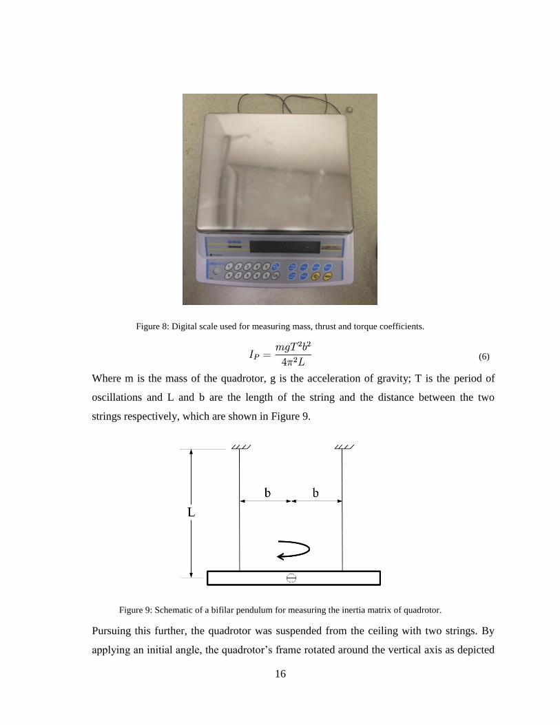
Figure 8: Digital scale used for measuring mass, thrust and torque coefficients. ........................ 16
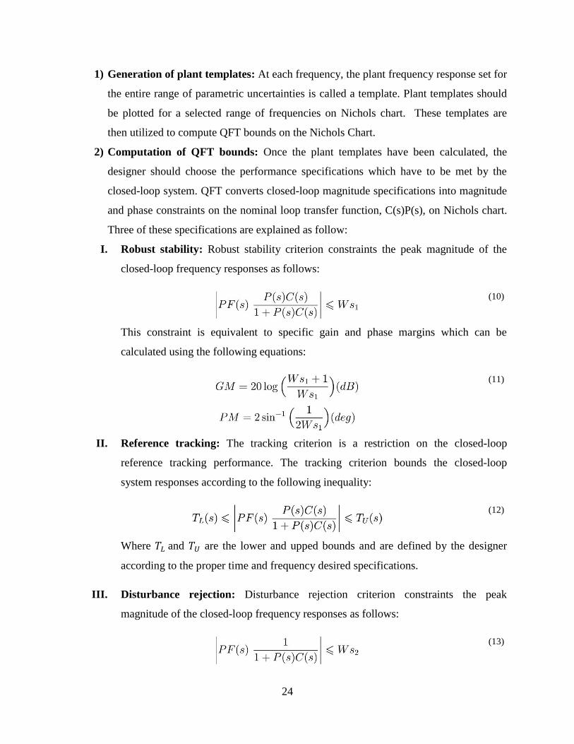
Figure 9: Schematic of a bifilar pendulum for measuring the inertia matrix of quadrotor. .......... 16
Figure 10: Experimental setup for thrust and torque coefficients measurement; (a) thrust
experimental setup; (b) torque experimental setup. ...................................................................... 17
Figure 11: Experimental values of thrust at five rotational speeds. .............................................. 18
Figure 12: Experimental values of toque at five rotational speeds. .............................................. 18
Figure 13: Block diagram showing entire system and controllers ................................................ 21
Figure 14: Yaw angle control structure; MD and AD are motor dynamics and attitude dynamics,
respectively. .................................................................................................................................. 22
Figure 15: Attitude control structure............................................................................................. 22
Figure 16: Two-degree-of-freedom QFT controller structure; PF(s) and C(s) are prefilter and
controller, respectively. ................................................................................................................. 23

vi
Figure 17: Two-degree-of-freedom QFT attitude controller structure; IPF and IC are inner loop
prefilter and inner loop controller, respectively. ........................................................................... 25
Figure 18: Roll and pitch plant templates at design frequencies. ................................................. 26
Figure 19: Robust stability bounds on Nichols chart at design frequencies. ................................ 27
Figure 20: Time responses of desired tracking bounds. ............................................................... 28
Figure 21: Reference tracking bounds on Nichols chart at design frequencies. ........................... 28
Figure 22: Disturbance rejection bounds on Nichols chart at design frequencies. ....................... 29
Figure 23: QFT design bounds and nominal loop transfer function before controller design on
Nichols chart at design frequencies (rad/s). .................................................................................. 29
Figure 24: QFT design bounds and nominal loop transfer function after controller design on
Nichols chart at design frequencies (rad/s). .................................................................................. 30
Figure 25: Linear system frequency responses using the QFT controller and prefilter for the
entire range of parametric uncertainties given in Table 2. ............................................................ 31
Figure 26: Linear system step-responses using the QFT controller and prefilter for the entire
range of parametric uncertainties given in Table 2. ...................................................................... 31
Figure 27: Membership functions for input position error in X and Y directions ........................ 32
Figure 28: Membership function for input position error in Z direction ...................................... 32
Figure 29: Membership functions for input velocity error in X, Y and Z directions ................... 33
Figure 30: Membership functions for output attitude angles (𝜃𝑑,𝜑𝑑) ......................................... 33
Figure 31: Membership function for output thrust, 𝑈1, 𝑑 ............................................................ 33
Figure 32: Input membership functions with input values. .......................................................... 34
Figure 33: Inputs and output membership functions for rule 1. ................................................... 35
Figure 34: Inputs and output membership functions for rule 2. ................................................... 36

vii
Figure 35: Implied fuzzy sets. ....................................................................................................... 36
Figure 36: Applied input torques and force to open loop system. ................................................ 39
Figure 37: Generated Euler angles, due to torques applied to open loop system. ........................ 39
Figure 38: Position alteration, due to torques and force applied to open loop system. ................ 39
Figure 39: Normalized nonlinear system step-responses using the QFT controller and prefilter for
entire range of parametric uncertainties given in Table 2. ............................................................ 40
Figure 40: Square-shaped trajectory in constant 5 m altitude....................................................... 41
Figure 41: Components of desired and actual attitude following the square-shaped trajectory
using QFT-Fuzzy controller for a typical simulation. .................................................................. 41
Figure 42: Corresponding control signals following the square-shaped trajectory using QFT-
Fuzzy controller for a typical simulation. ..................................................................................... 42
Figure 43: Components of desired and actual position following the square-shaped trajectory
using QFT-Fuzzy controller for a typical simulation. .................................................................. 43
Figure 44: Square-shaped trajectory and followed actual trajectory using QFT-Fuzzy controller
for the entire range of uncertainties listed in Table 2. .................................................................. 43
Figure 45: Custom-made test stand to evaluate designed attitude controller ............................... 45
Figure 46: Experimental normalized step-responses using QFT controller and prefilter in
tracking various desired step inputs having magnitudes of 5°, 15° and 25°. ................................ 45
Figure 47: Six experimental responses of quadrotor on a gimbal to 20 additive pitch angle
disturbance using the QFT controller; Disturbance was applied around 2 second as indicated by
the triangles. .................................................................................................................................. 46

viii
Figure 48: Corresponding control signals for the quadrotor on a gimbal under 20 additive pitch
angle disturbance using the QFT controller; triangles show the time when disturbance was
applied. .......................................................................................................................................... 46
Figure 49: Six experimental responses of the hovering quadrotor to 20 additive pitch angle
disturbance using the QFT controller; Disturbance was applied around 2 second as indicated by
the triangles. .................................................................................................................................. 47
Figure 50: Corresponding control signals of the hovering quadrotor under 20 additive pitch
angle disturbance using the QFT controller; triangles illustrate the time when disturbance was
applied. .......................................................................................................................................... 47
Figure 51: Square-shaped trajectory in constant 5 m altitude consists of eight waypoints. ......... 48
Figure 52: Components of desired and actual attitude following the square-shaped trajectory
using combined QFT and ArduCopter position controller for a typical experiment. ................... 49
Figure 53: Corresponding control signals following the square-shaped trajectory using combined
QFT and ArduCopter position controller for a typical experiment. ............................................. 50
Figure 54: Components of desired and actual position following the square-shaped trajectory
using combined QFT and ArduCopter position controller for a typical experiment. ................... 51
Figure 55: Square-shaped trajectory and followed actual trajectory using combined QFT and
ArduCopter position controller for a typical experiment. ............................................................. 51
Figure 56: Components of desired and actual attitude following the square-shaped trajectory
using QFT-Fuzzy controller for a typical experiment. ................................................................. 53
Figure 57: Corresponding control signals following the square-shaped trajectory using QFT-
Fuzzy controller for a typical experiment. .................................................................................... 54

ix
Figure 58: Components of desired and actual position following the square-shaped trajectory
using QFT-Fuzzy controller for a typical experiment. ................................................................. 55
Figure 59: Square-shaped trajectory and followed trajectory using QFT-Fuzzy controller for five
experiments. .................................................................................................................................. 55
Figure 60: Square-shaped trajectory and followed trajectory using ArduCopter controller for five
experiments. .................................................................................................................................. 56

x
List of tables
Table 1: Summary of previous work on control of quadrotors ..................................................... 12
Table 2: Parameters of quadrotor under investigation and their ranges of uncertainties .............. 19
Table 3: Table of fuzzy rules to determine fuzzy controller outputs ............................................ 34
Table 4: Comparison of results of five experiments using QFT and ArduCopter attitude
controllers ..................................................................................................................................... 49
Table 5: Comparison of results of five experiments using QFT-Fuzzy and ArduCopter controllers
....................................................................................................................................................... 52

1
Chapter
1 Introduction
Unmanned Aerial Vehicles (UAVs) have emerged as popular platforms in various applications
such as rescue missions [1], firefighting [2], and surveillance [3]. These vehicles can be operated
in dangerous environments with relatively low cost and without putting human at risk [4]. A
specific kind of UAVs, the quadrotors, has attracted tremendous attention in the contemporary
robotics because of their two main advantages over other vertical takeoff and landing UAVs.
First, they are mechanically simple. This qualification reduces design and maintenance effort.
Second, the sizes of rotors are smaller than helicopter’s main rotor; consequently, they have less
kinetic energy while flying, which reduces the damage in case of collision [5]. As a result of this
popularity, a broad range of control techniques have been designed and evaluated to improve the
flight performance of quadrotors.
1.1 Problem statement
1.1.1 Motivation and problem definition
The performance of the quadrotors can be significantly disturbed in presence of wind. Despite
the performance improvements caused by utilizing effective control strategies, many designs
have neglected model uncertainties and external disturbances in their controller design
procedures [4]. In the current literature on quadrotors, several simulation studies have
concentrated on the effects of the external disturbances on the flight. However, most of the
studies in disturbance rejection area have not been validated experimentally. More recently,
particular researchers have considered disturbance rejection at the controller design phases and
experiments. Although, these techniques have been verified theoretically and experimentally,
they suggest complex nonlinear control strategies which can be challenging to be implemented.

2
1.1.2 Proposed solution
In this thesis, we design simple-to-implement attitude and position controllers to render a robust
and accurate trajectory tracking in the presence of external disturbance and model uncertainties.
QFT method is chosen to design a linear fixed gain attitude controller. QFT was first developed
by Horowitz in early 1960 [6]. It is a controller design technique in frequency domain using
Nichols chart to develop a desired robust design over a specified region of plant uncertainties.
Using the QFT method it is guaranteed that the desired performance specifications are satisfied
in spite of the system uncertainties and disturbances. The transparent design procedure of QFT
method facilitates the design process in reaching a trade-off between controller’s performance
and complexity. Using QFT method, system stability, disturbance rejection and response
tracking criteria for the entire range of plant uncertainties are taken into account at the controller
design phase. Considering the fact that fuzzy logic controllers are effective replacements for
experienced human operators [7], the fuzzy logic technique is also used to design a position
controller. The combined QFT attitude and fuzzy position controller, which hereafter is referred
to as QFT-Fuzzy controller, is shown to outperform the in-built ArduCopter controller [8], in
terms of trajectory tracking.
1.2 Thesis formulation
1.2.1 Thesis statement
This thesis aims to develop a simple-to-implement attitude controller based on QFT technique.
Disturbance rejection and plant parametric uncertainties are considered in the attitude controller
design phase. Additionally, it aims to design a simple-to-implement position controller based on
fuzzy technique which is capable of providing accurate trajectory tracking. The QFT-Fuzzy
controller is implemented and evaluated experimentally and the performance, in terms of
trajectory tracking, is compared with the ArduCopter controller.
1.2.2 Thesis objectives
The primary objectives of this thesis are twofold: i) to design easy-to-implement attitude and
position controllers which are capable of robust and accurate trajectory tracking in the presence

3
of disturbances and model uncertainties, and ii) to experimentally investigate the effectiveness of
the proposed controllers in accomplishing trajectory tracking tasks.
1.2.3 Research questions
The major questions which will be addressed in this research are:
1. Is the proposed QFT attitude controller capable of attenuating disturbances?
2. Can the proposed QFT attitude controller outperform the ArduCopter attitude controller in
terms of reference tracking?
3. Can the proposed QFT-Fuzzy position controller outperform the ArduCopter controller in
terms of trajectory tracking?
1.3 Thesis overview
The remainder of this thesis is as follows. Chapter 1 provides an introduction, outline of the
research and the structure of the thesis. An overview of quadrotor motion and the previous work
on quadrotors design and control are reviewed in Chapter 2. Chapter 3 presents the modeling of
the quadrotor and motors. The parameters of the quadrotor under investigation are identified and
uncertainties assigned to the nominal values are listed in this chapter. Chapter 4 presents the
controllers design procedures. It begins with and outline of the QFT design process. The
performance criteria for the inner loop QFT attitude controller are designed. The development of
QFT attitude and fuzzy position controllers are also explained in Chapter 4. The Simulation and
experimental results which validate the efficacy of the proposed controllers are presented in
Chapter 5. Chapter 6 provides the conclusion and puts forward several suggestions for future
work.

4
Chapter
2 Literature Review
2.1 Overview of quadrotors motion
A quadrotor is a mechanically simple Unmanned Aerial Vehicle (UAV) consisting of four
motor/propeller units in cross configuration as shown in Figure 1. Quadrotors are under-actuated
systems, i.e., they have four motors to control six degrees of freedom. Quadrotors are inherently
unstable. As a result, they require an on-board computer/flight controller for stabilization. The
flight controllers usually consist of MEMs gyroscopes, accelerometers and barometers to
estimate the position and orientation of the quadrotor.
Figure 1: Quadrotor made by 3D Robotics (from [9])
Each motor produces a thrust, T, and a torque, Q, that depends on its rotational speed. In
addition, each motor spins in a direction opposite to the motors on each side of it to balance the
total torque. Quadrotor motion is controlled by increasing or decreasing the rotational speeds of
four downward thrusting motor/propeller units. Pursuing this further, pitch angle, θ, is controlled
by speeding up motor no. 3 while slowing down motor no. 1 or vice versa, as shown in Figure 2:

5
(a). Similarly, roll angle, φ, is controlled by slowing down motor no. 4 while speeding up motor
no. 2 or vice versa as shown in Figure 2: (b). Moreover, yaw angle, ψ, is controlled by speeding
up motors no. 1 and no. 3 while slowing down motors no. 2 and no. 4 or vice versa as depicted in
Figure 2: (c). Finally, the altitude, z, is controlled by speeding up or slowing down all motors as
illustrated in Figure 2: (d).
Figure 2: Changes in position and orientation of quadrotor, due to spinning rotors; (a) generated pitch angle (b)
generated roll angle; (c) generated yaw angle; (d) altitude alteration; T is generated thrust; Q is generated torque.
The horizontal motion in horizontal plane is caused by leaning the quadrotor in the desired
direction. The more the vehicle leans, the faster it travels.
2.2 Previous work on control of quadrotors
Over the last fifteen years, considerable attention has been drawn to quadrotors. Plenty of
research studies have investigated the design [10, 11, 5, 12, 13, 14, 15, 16, 17, 18], dynamics and
control [12, 13, 17, 19, 20, 4, 21, 22, 23, 24], trajectory generation [25, 26, 27], payload
transportation [25, 28], obstacle and collision avoidance [11, 12, 18] and aerodynamics [5, 13] of
these contemporary robots. The current section provides an overview of the selected projects on
quadrotors design and control.

6
Many custom-built quadrotors have been built at research facilities and universities such as,
Mesicopter at Stanford University [10], Starmac I and Starmac II at The Stanford Testbed of
Autonomous Rotorcraft for Multi-Agent Control (STARMAC), at Stanford University [11, 5,
29], OS4 quadrotor at EPLF [30], X4-Flyer Mark I and Mark II at Australian National University
(ANU) [13], and quadrotors built at Pennsylvania State University [31], Cornell University and
Swiss Federal Institute of Technology [31], European Aeronautic Defense and Space Company
[31], University of British Columbia [32], University of Calgary [17], Korea Institute of
Industrial Technology (KITECH) [16] and Konkuk University (KU) [18].
Due to high design efforts and time considerations involved in building a new purpose-built
quadrotor from scratch, the number of research studies using these quadrotors is low, and mostly
commercially-available quadrotors and off-the-shelf components are used to conduct
experiments [13]. Currently, there are numerous commercially available quadrotors which are
being used as a hobby or for research purposes. Draganfly Innovation Inc. introduced their first
multi-rotor named Draganflyer in 1999. Since then, plenty of multi-rotors and quadrotors have
been developed by this company. Draganflyer Guardian, Draganflyer X4-P and Draganflyer X4-
ES are three of their most recent products. Several quadrotors also have been made by 3D
Robotics Company including IRIS and Solo. Phantom 3 series is another group of commercially
available quadrotors made by DJI. Numerous research studies have been done using
commercially available quadrotors. For instance, Draganflyer [19, 4, 23, 33], Draganflyer III
[34], Blade mQX [35], Ascending Technologies Hummingbird [24], Ascending Technologies
Pelican [36], Smart Xcopter [28, 37] and Aeroquad [38].
The X4-Flyer Mark I developed at Australian National University. The design and fabrication of
Mark I for indoor flight was published by Pounds et al. [39] in 2002. Due to insufficient thrust
and unstable dynamic behaviour, the research team tuned the mechanical design and developed
X4-Flyer Mark II. Mark II is a quadrotor with innovative design using inverted teetering rotors
[13]. Pounds et al. [39] developed a pilot augmentation control system for Mark I. A pilot
augmentation controller aims to alter the dynamic response of the system in a way to make it
possible for a trained pilot to control the system. The proposed controller was a double lead
compensator designed by root locus method. In 2007, they used a conventional Proportional-

7
Integral-Derivative (PID) controller for Mark II [40]. In the hover experimental test, the
controller stabilized the roll and pitch with the error of 0.5° [13].
Figure 3: X4-Flyer Mark II (from [40])
In 2004, Castillo et al. [19, 33] proposed a Lyapunov-based attitude and horizontal position
controllers for a quadrotor. The proposed techniques for altitude and yaw control were feedback
linearization and Proportional-Derivative (PD), respectively. Based on the experiments, the error
of Euler angles were less than 3° during hover flight. A Draganflyer quadrotor was used to
conduct the experiments.
The OS4 quadrotor was built in École Polytechnique Fédérale de Lausanne (EPLF) and aimed to
provide full autonomous flight in indoor environments. The OS4 design and control were
simultaneously developed based on a systematic design optimization method [41]. The final OS4
quadrotor is an entirely purpose-built vehicle including custom frame, rotors and avionics [13].
Bouabdallah et al. [12, 30, 41, 42, 43] proposed several linear and nonlinear controllers during
2004-2007. The performances of the designed controllers were analyzed by simulation and
experimental tests and the results were published in several papers. To pursue this further, in
2004, Bouabdallah et al. [41] designed a Lyapunov-based attitude controller and an altitude
controller based on feedback linearization method. The performances of the controllers were
tested in a simulation study and on OS4 test-bench developed in EPLF. OS4 test-bench allows
only three rotational degrees of freedom (roll, pitch and yaw) in order to reduce potential system
damage. In spite of test-bench delays and actuator saturation, the experiments showed the ability

8
of the proposed control to stabilize the system. In 2005, two more attitude controllers based on
backstepping and sliding-mode techniques were designed and tested on OS4 test-bench in EPLF.
The backstepping control reported to stabilize the quadrotor even for relatively critical initial
conditions and strong disturbances, although it provided delicate stabilization in hover flight
[30]. It could stabilize the roll angle in less than 5 s for 32° initial condition. In comparison, the
sliding-mode controller stabilized the roll angle in 8 s for 26° initial condition. A visible
shattering effect disturbed the measurements especially for the yaw angle [42]. In 2007, two
more attitude controllers based on PID and Linear-Quadratic (LQ) control techniques were
designed and studied experimentally on OS4 quadrotor. They concluded that the PID controller
was able to stabilize the quadrotor even in the presence of minor perturbations. On the other
hand, the performance of the LQ controller reported to be “average” due to neglecting the
actuators dynamics [43]. Both PID and LQ controllers presented poor disturbance rejection
performances [30].
Figure 4: OS4 Quadrotor (from [12])
In their most recent effort, PID and backstepping controller design techniques were combined
and an integral backstepping controller was designed. The proposed method was used for
attitude, altitude and position control and was tested on OS4 quadrotor. The roll, pitch and yaw
showed bounded oscillations of 0.1 rad in amplitude due to slow dynamics of the actuators. The
performance of the quadrotor was also tested by a waypoint tracking mission. The mission was

9
to climb to 1 m above the ground and follow a four waypoint square trajectory with 2 m length.
The results showed 10% overshoot in tracking while the whole mission took 20 s to be done
[12].
The Stanford Testbed of Autonomous Rotorcraft for Multi-Agent Control (STARMAC) is
another project conducted at Stanford University. The first generation, Starmac I was developed
from 2003 to 2005 [5]. Starmac I was used to implement and validate multi-agent control
algorithms and autonomous flight in constrained environments [11]. The quadrotors used in this
project were basically Draganflyer III with replaced onboard electronics that was designed and
assembled in Stanford [13]. Later on, Starmac II quadrotor was developed to satisfy autonomous
position control, perception of the environment and onboard implementation of multi-vehicle
algorithms. The vehicle frame and propulsion system were designed to provide minimum weight,
maximum payload capacity and maximum flight time. In addition, the sensors and control
electronics were selected by the team to provide sufficient computation power and to enable
autonomous multi-agent missions.
Figure 5: Starmac II (from [5])
The focus of STARMAC project is to investigate multi-agent control algorithms for applications
like collision and obstacle avoidance, cooperative search and trajectory generation [5]. The
attitude controller of each vehicle is designed based on Linear-Quadratic Regulator (LQR)
method. The performance of the controller was satisfactory at low thrust levels. But at higher
levels the performance was affected by generated vibrations. This problem was solved by
lowering the costs on attitude deviation. As a result, the noise rejection performance improved at
the cost of worst tracking performance. The sliding-mode technique was used to design the

10
altitude controller [11]. In 2007, Hoffmann et al. [29] derived more precise dynamic model for
Starmac II quadrotors. They derived quadrotors aerodynamics for non-zero free-stream velocities
based on conventional helicopter momentum and blade element theory. Pursuing this further;
they considered the effect of thrust alteration caused by changes in angle of attack or transitional
motion. In addition, blade flapping phenomenon was taken into account. Based on these
aerodynamic models, a feedforward compensator was designed which attenuated the
perturbations generated by these two aerodynamic phenomena. The attitude controller proposed
by Hoffmann et al. [5, 29] is a conventional PID controller with an additional zero, giving
angular acceleration feedback. Using an additional zero, higher values for gains can be chosen
which increase the system bandwidth. Additionally, feedback linearization and conventional PID
techniques were used to design altitude and position controllers, respectively. The flight
scenarios show an error under 0.1 m for indoor square trajectory tracking at 0.5 m/s speed and an
error under 0.5 m for outdoor straight line trajectory tracking at 2 m/s speed. In 2009, Waslander
et al. [20] used the identical extended dynamics equations for the quadrotor to improve its
positioning performance. They developed a wind estimation algorithm to eliminate the effect of
wind on feedback position control law. Simulation studies were done to test the performance of
the proposed algorithm.
GRASP Multiple Micro Air Vehicle (MAV) testbed at the University of Pennsylvania has
focused on quadrotors control and multi-rotor control algorithms. In 2010, Michael et al. [44, 45]
described the GRASP testbed including controllers implemented on the platforms. The attitude
controller is a PD designed for near hover state where roll and pitch angles are small. Two
controllers are proposed for position controlling: A Hover control and a 3D trajectory control.
The hover controller is a conventional PID which controls the desired linear accelerations and is
responsible to maintain the position of the quadrotor while it hovers. The 3D trajectory controller
is a PD controller with additional feedforward desired acceleration term. The output of 3D
trajectory controller is desired linear acceleration which is used to compute the desired Euler
angles using equations of motion. The indoor trajectory tracking scenario showed an error under
0.04 m in horizontal plane for following a circle trajectory with 1 m radius at a rate of 1.5 m/s
and an error under 0.03 m in vertical direction. The same control scheme was used by Mellinger
in his thesis, published in 2012 at the University of Pennsylvania [25]. Ascending Technologies

11
Hummingbird is chosen as the experimental platform in GRASP. The reasons for choosing the
Hummingbird are its proper size, weight, durability, payload capacity and flight time [44].
In 2012, Erginer et al. [46] proposed and performed a set of experiments using a classical PD
and a hybrid fuzzy PD controller for a quadrotor. The performances of the controllers were
compared using several simulations and experiments. Based on the simulation studies, the hybrid
fuzzy PD controller showed 3.9 to 84.7 % less error in simulations. Based on the experiments,
both controllers were capable of stabilizing the quadrotor; however, the fuzzy controller showed
better performance in terms of disturbance rejection and settling time. Based on the provided
figures, the fuzzy attitude controller is able to attenuate the disturbances of around 20° in about 2
s.
Xu et al. [47] designed QFT attitude and position controllers for a quadrotor. The equations of
motion were transferred to body frame to reduce the time and effort involved in computing the
trigonometric functions. The performance of the controller was verified experimentally. The
average error for 623 s of hovering is 0.39 m and 0.22 m Mean Square Error (MSE) in east and
north positions respectively. The trajectory tracking error is around 0.22 m MSE for following a
straight line.
In 2014, Alexis et al. [4, 23] designed and experimented a Constrained Finite Time Optimal
Attitude Controller (CFTOC) for a quadrotor to perform under strong wind disturbances. An
extended model of the quadrotor considering external disturbances as additive terms to the
angular and linear accelerations was derived. The equations of motion were linearized for a
number of operating points resulting a set of piecewise affine (PWA) models. In addition, the
states and inputs of the quadrotor were constrained in each linearized subsystem. The CFTOC
computes the optimum control vector which minimizes the cost function considering all of the
constraints for the corresponding linearized subsystem and wind model. The experimental study
validated the efficiency of the CFTOC in both attitude set-point maneuvers and wind gust
attenuation. The MSE for roll and pitch for both the cases with and without considering wind
disturbances are 1.6984 and 4.0308 square radians, respectively. The experimental platform
consists of a modified Draganflyer quadrotor.

12
In 2014, Dong et al. [24] developed and experimented a flight controller with disturbance
observer (DOB) for a quadrotor. An extended model of the quadrotor considering model
mismatches, input delays and external disturbances as additive terms was derived. Position and
attitude controllers were designed based on backstepping technique. DOB serves as the outer
loop compensator to attenuate external disturbances. According to the experiment, the quadrotor
should reach a point in 0.85 m while an artificially created wind disturbances were affecting its
flight. The results show that the quadrotor stabilizes with a steady-state error of 2% within about
2 s. The same experiment for a quadrotor without DOB shows 150% more steady-state error.
The quadrotor used in this research was an Ascending Technologies Hummingbird.
The control techniques which have been used for controller design in selected projects are
summarized in Table 1.
Table 1: Summary of previous work on control of quadrotors
Controller type
Experimental evaluation with
custom-built quadrotors
Experimental evaluation with
commercially-available quadrotors
Linear [5], [43] [11], [4], [23], [25], [44], [45], [47]
Nonlinear
Backstepping [42] [24]
Lyapunov-based [42] [19], [41]
Fuzzy [46]
2.3 Summary
Chapter 2 provided an overview of quadrotors’ motion in space. Changes in orientation and
position of a quadrotor, due to spinning rotors were discussed. Additionally, an overview of
some selected projects on quadrotors design and control were presented.

13
Chapter
3 Modeling
3.1 Quadrotor dynamics
The derivation of the equations of motion for a quadrotor requires two reference frames: The
earth fixed frame and body fixed frame (see Figure 6).
Figure 6: Quadrotor free body diagram; earth fixed frame {XYZ} and body fixed frame {xyz}
The world fixed frame is defined by axes X, Y and Z with Z pointing upward. The body fixed
frame is attached to the center of mass of the quadrotor with x pointing to rotor 1, y pointing to
rotor 4 and z perpendicular to the plane of rotors pointing upward in hover state. The position of
the quadrotor is shown by r. Z – X – Y Euler angles sequence ( , , ), referred to as yaw, roll and
pitch, respectively, is used to model the orientation of the quadrotor in the earth fixed frame.
Pursuing this further, to get from the world fixed frame to the body fixed frame, first, there is a
rotation around z by the yaw angle, ψ, then a rotation around intermediate x axis by the roll
angle, φ, and finally a rotation around the y axis by the pitch angle, θ. The final rotation matrix
from the body fixed frame to the world fixed frame is as follows [25]:

14
(1)
The thrust, 𝑇𝑖, and torque, 𝑄𝑖, generated by each rotor acts perpendicular to the plane of rotors.
Vehicle mass is m, the length between rotors and z axis is called quadrotor arm and is shown by
l, acceleration due to gravity is g and I is the inertia matrix referenced to the center of the mass of
the quadrotor along the x – y – z axes. Based on the Newton’s second law of motion for a rigid
body, the governing equations for linear and angular accelerations can be written as follows [25]:
(2a)
(2b)
The components of angular body rates are p, q and r. These rates are measured by gyroscopes
and are related to the derivatives of Euler angles according to the following equation [25]:
(3)
3.2 Motor dynamics
Each motor with angular speed 𝛺𝑖 produces a thrust force, 𝑇𝑖, and a torque, 𝑄𝑖, according to
these equations:
(4a)
(4b)
15
Where kT and kQ are thrust and drag coefficient, respectively. These coefficients are functions of
air density, rotor radius and non-dimensional rotor thrust and torque coefficients [40]. The exact
relationship between the actual and desired motor speed is a complex function of motor
controller and motor/propeller dynamics [21]. However, in previous studies first order model
was successfully used at controller design phase for simplicity [5, 12, 21]. The actual rotor speed
is therefore related to the desired rotor speed by the following equation:
(5)
Where km is the motor time constant.
3.3 Parameter identification
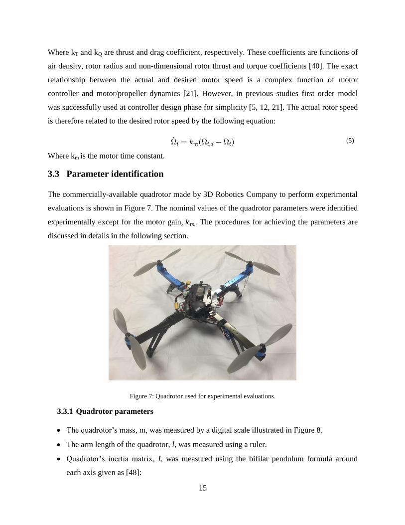
The commercially-available quadrotor made by 3D Robotics Company to perform experimental
evaluations is shown in Figure 7. The nominal values of the quadrotor parameters were identified
experimentally except for the motor gain, 𝑘𝑚. The procedures for achieving the parameters are
discussed in details in the following section.
Figure 7: Quadrotor used for experimental evaluations.
3.3.1 Quadrotor parameters
The quadrotor’s mass, m, was measured by a digital scale illustrated in Figure 8.
The arm length of the quadrotor, l, was measured using a ruler.
Quadrotor’s inertia matrix, I, was measured using the bifilar pendulum formula around
each axis given as [48]:
16
Figure 8: Digital scale used for measuring mass, thrust and torque coefficients.
(6)
Where m is the mass of the quadrotor, g is the acceleration of gravity; T is the period of
oscillations and L and b are the length of the string and the distance between the two
strings respectively, which are shown in Figure 9.
Figure 9: Schematic of a bifilar pendulum for measuring the inertia matrix of quadrotor.
Pursuing this further, the quadrotor was suspended from the ceiling with two strings. By
applying an initial angle, the quadrotor’s frame rotated around the vertical axis as depicted

17
in Figure 9. By calculating the periods of oscillations, the inertia of the frame can be
measured using (6).
3.3.2 Motors/propeller parameters
Two experimental setups were designed to measure the values of thrust and torque
coefficients, kT and kQ for the rotor/propeller units of the system under investigation. To
measure these values the relation between brushless motor speed and generated thrust and
torque should be evaluated. Figure 10: (a) and (b) show experimental setups for thrust and
torque calculations, respectively.
Figure 10: Experimental setup for thrust and torque coefficients measurement; (a) thrust experimental setup; (b)
torque experimental setup.
In the experimental setup illustrated in Figure 10: (a) the propeller is flipped to generate a
downward thrust. The generated thrust is measured at several rotational speeds using the
digital scale illustrated in Figure 8 and the results are plotted in Figure 11. Similarly, the
produced torque is measured at several rotational speeds using the digital scale illustrated
in Figure 8 and the results are plotted in Figure 12. The values of thrust and torque
coefficients are calculated by adding a linear trend line to the plots. According to (4) the
slopes of the trend lines are equal to the thrust and torque coefficients respectively.

18
Figure 11: Experimental values of thrust at five rotational speeds.
Figure 12: Experimental values of toque at five rotational speeds.
The values of kT and kQ measured for the rotor/propeller units under investigation are valid
for the temperature and pressure at which the experiments were performed (temperature =
25° and pressure = 102 kPa). These values may change, if the pressure and temperature
conditions vary considerably or if a different rotor is used.
In (5), the motor gain 𝑘𝑚 should be measured experimentally for each motor/propeller unit.
However, the value of motor gain for the system used in this study was estimated by the
values which have been given in previous studies for similar rotors due to the shortage of
equipment. ±25% error for the estimated value is taken into account at the controller design
phase. The identified nominal parameters for the system under investigation and
uncertainties assigned to them are given in Table 2.

19
Table 2: Parameters of quadrotor under investigation and their ranges of uncertainties
Parameter Symbol Value Uncertainty Range
(%) Unit
Inertia on x axis 𝐼𝑥𝑥 12.3e-3 ±25 Kgm2
Inertia on y axis 𝐼𝑦𝑦 12.3e-3 ±25 Kgm2
Inertia on z axis 𝐼𝑧𝑧 23.0e-3 ±25 Kgm2
Motor’s time constant 𝑘𝑚 0.1 ±25 s−1
Mass m 1.26 - Kg
Arm length l 0.26 - M
Thrust coefficient 𝑘𝑇 1.5e-6 - Ns2
Drag coefficient 𝑘𝑄 2.5e-8 - Nms2
The ranges of uncertainties assigned to the elements of inertia are not measurement uncertainties;
these ranges represent the plant parametric uncertainties. The designed controller has to meet the
criteria if the plant parameters change within the mentioned ranges.
3.4 Linearized model
In order to design the attitude controller based on QFT method, the attitude dynamic model (2b)
is linearized around an operating point corresponds to the hover state. For small Euler angles
near hover state, following simplifications can be used:
(7)
The linearized attitude model is given by:
(8)
3.5 Summary
In Chapter 3, the equations of motion of a quadrotor were derived. The motor/propeller dynamics
were also discussed. The quadrotor and motor/propeller parameters were identified. The
procedures and instruments for measuring these parameters were presented. Moreover, the
linearization process was described in this chapter. Finally, the measured parameters and the
uncertainties assigned to each parameter were outlined. The dynamic equations for quadrotor and

20
motor/propeller units described in this chapter will be used in Chapter 4 for attitude and position
controllers design procedures.

21
Chapter
4 Controller Design
The main focus of this research was on the design and implementation of simple attitude and
position controllers to render a robust and accurate trajectory tracking in presence of external
disturbance and model uncertainties. This chapter describes the design and implementation of the
proposed controllers for a quadrotor in details. The quadrotor is controlled by nested feedback
loops depicted in Figure 13.
Figure 13: Block diagram showing entire system and controllers
The inner loop attitude controller uses gyros and accelerometers to control the orientation of the
quadrotor and runs at approximately 400 Hz, while the outer loop position controller uses GPS
and accelerometers to monitor the position of the quadrotor and runs at approximately 100 Hz.
In order to validate the sampling frequency, the Power Spectral Density (PSD) of the signal must
be obtained. Using PSD it can be known if the signal is broadband or narrowband. According to
the Nyquist sampling theorem, the sampling frequency must at least be twice the cutoff
frequency for narrowband signals or twice the highest frequency for broadband signals. PSD can
be obtained from the Fourier Transform of the signal. Note that we are not allowed to apply Fast
Fourier Transform (FFT) to a signal without examining the stationarity behaviour of the signal,
as FFT is applied only to a stationary signal. To find if the signal is stationary, the stationarity
test must be performed. More details about the stationarity and sampling tests are provided in
[49, 50]. The inner loop controller is designed by QFT method and based on the linearized

22
angular dynamics of the quadrotor given by (8). The QFT controller and prefilter are responsible
to control the roll and pitch angles. Considering the fact that the value of the yaw angle is not
important for trajectory tracking purposes as long as the exact value of the angle is known, a
simple PID rate controller is used to control the yaw as illustrated in Figure 14.
Figure 14: Yaw angle control structure; MD and AD are motor dynamics and attitude dynamics, respectively.
The outer loop controller is designed based on the fuzzy logic technique. The vector of desired
rotational speeds of rotors can be calculated from the desired control input torques, 𝑈2,𝑑, 𝑈3,𝑑
and 𝑈4,𝑑, and thrust , 𝑈1,𝑑, by inverting the following equation:
(9)
4.1 Inner loop attitude controller design
The attitude control structure is shown in Figure 15. The inputs of the controller are the desired
and actual Euler angles and the outputs are the desired roll, pitch and yaw moments, 𝑈2,𝑑, 𝑈3,𝑑
and 𝑈4,𝑑. The attitude controller, AC, is designed using QFT method. The following section
provides a brief description of QFT control technique.
Figure 15: Attitude control structure

23
4.1.1 QFT design process
Quantitative feedback theory is a controller design technique in frequency domain using
Nichols chart to develop a desired robust design over a specified region of plant uncertainties.
The transparent design procedure of QFT method facilitates the design process in reaching a
trade-off between controller’s complexity and performance. QFT method provides several
performance specifications which can be chosen by the designer for any single loop closed-
loop system. Namely, gain and phase margins, sensitivity reduction, disturbance rejection at
plant input, control effort minimization, tracking bandwidth, classical two-degree-of-freedom
tracking problem, rejection of disturbances at plant output and rejection of plant input
disturbances. The main advantages of QFT can be summarized as follow [51, 52]:
The final designed controller is robust against structured plant parametric uncertainties.
Design limitations are transparent from the beginning and during the design process.
The achievable performance specifications can be determined in the early stages of design.
The trade-offs between performance specifications and controller complexity and
bandwidth are transparent at each frequency.
Figure 16 illustrates the two-degree-of-freedom QFT attitude controller structure where
P(s) denotes uncertain plant. Employing QFT method, a prefilter, PF(s), and a controller,
C(s), are designed such that the considered performance criteria are satisfied (readers are
referred to [6] for detailed QFT design procedure). QFT design involves three basic steps
that are discussed in details as follows.
Figure 16: Two-degree-of-freedom QFT controller structure; PF(s) and C(s) are prefilter and controller, respectively.
24
1) Generation of plant templates: At each frequency, the plant frequency response set for
the entire range of parametric uncertainties is called a template. Plant templates should
be plotted for a selected range of frequencies on Nichols chart. These templates are
then utilized to compute QFT bounds on the Nichols Chart.
2) Computation of QFT bounds: Once the plant templates have been calculated, the
designer should choose the performance specifications which have to be met by the
closed-loop system. QFT converts closed-loop magnitude specifications into magnitude
and phase constraints on the nominal loop transfer function, C(s)P(s), on Nichols chart.
Three of these specifications are explained as follow:
I. Robust stability: Robust stability criterion constraints the peak magnitude of the
closed-loop frequency responses as follows:
(10)
This constraint is equivalent to specific gain and phase margins which can be
calculated using the following equations:
(11)
II. Reference tracking: The tracking criterion is a restriction on the closed-loop
reference tracking performance. The tracking criterion bounds the closed-loop
system responses according to the following inequality:
(12)
Where 𝑇𝐿 and 𝑇𝑈 are the lower and upped bounds and are defined by the designer
according to the proper time and frequency desired specifications.
III. Disturbance rejection: Disturbance rejection criterion constraints the peak
magnitude of the closed-loop frequency responses as follows:
(13)

25
3) Controller and prefilter design: The nominal loop transfer function has to be shaped
such that it satisfies the QFT bounds at each frequency. The process of shaping the
nominal loop transfer function is done by adding zeros and poles to the controller
transfer function, C(s), and is called loop shaping. During this transparent trial and error
process, the designer is able to consider the trade-offs between controller complexity
and performance. In addition, a prefilter has to be designed to put the closed-loop
frequency responses in the desired tracking envelop using Bode plot. Prefilter design
procedure is also done by adding zeros and poles to the prefilter transfer function, PF(s),
during a trial and error process.
4.1.2 Inner loop QFT attitude controller
Figure 17 illustrates the two-degree-of-freedom QFT attitude controller structure where MD
and AD denote motor dynamics and linear attitude dynamics, respectively. Employing QFT
method, a prefilter, IPF, and a controller, IC, are designed such that the considered
performance criteria are satisfied.
Figure 17: Two-degree-of-freedom QFT attitude controller structure; IPF and IC are inner loop prefilter and inner
loop controller, respectively.
1) Generation of plant templates: The roll and pitch plants consist of the linearized system
model (8) and motor dynamics (5) in cascade form as depicted in Figure 17. The linearized
attitude equations of motion are decoupled about each axis, consequently control input
torques can be implemented independently. The plant and the values of uncertain plant
parameters for pitch angle are as follows:
(14a)

26
(14b)
Similarly, the plant and the values of uncertain plant parameters for roll angle are as
follows:
(15a)
(15b)
Due to identical dynamics and quadrotor parameters for the pitch and roll angles, the
design procedure and experiments are done only for the pitch angle. The pitch plant (14a)
frequency responses for the entire range of uncertainties listed in Table 2 are plotted on the
Nichols chart for a selected range of frequencies. The design frequencies are selected as
𝜔 = {0.01, 0.06, 1, 5, 10, 20, 50, 100, 200, 400} rad/s. The generated plant templates are
shown in Figure 18.
Figure 18: Roll and pitch plant templates at design frequencies.
2) Computation of QFT bounds: Three QFT performance specifications are considered in
this thesis, namely, robust stability, disturbance rejection at plant output and tracking
criteria.
27
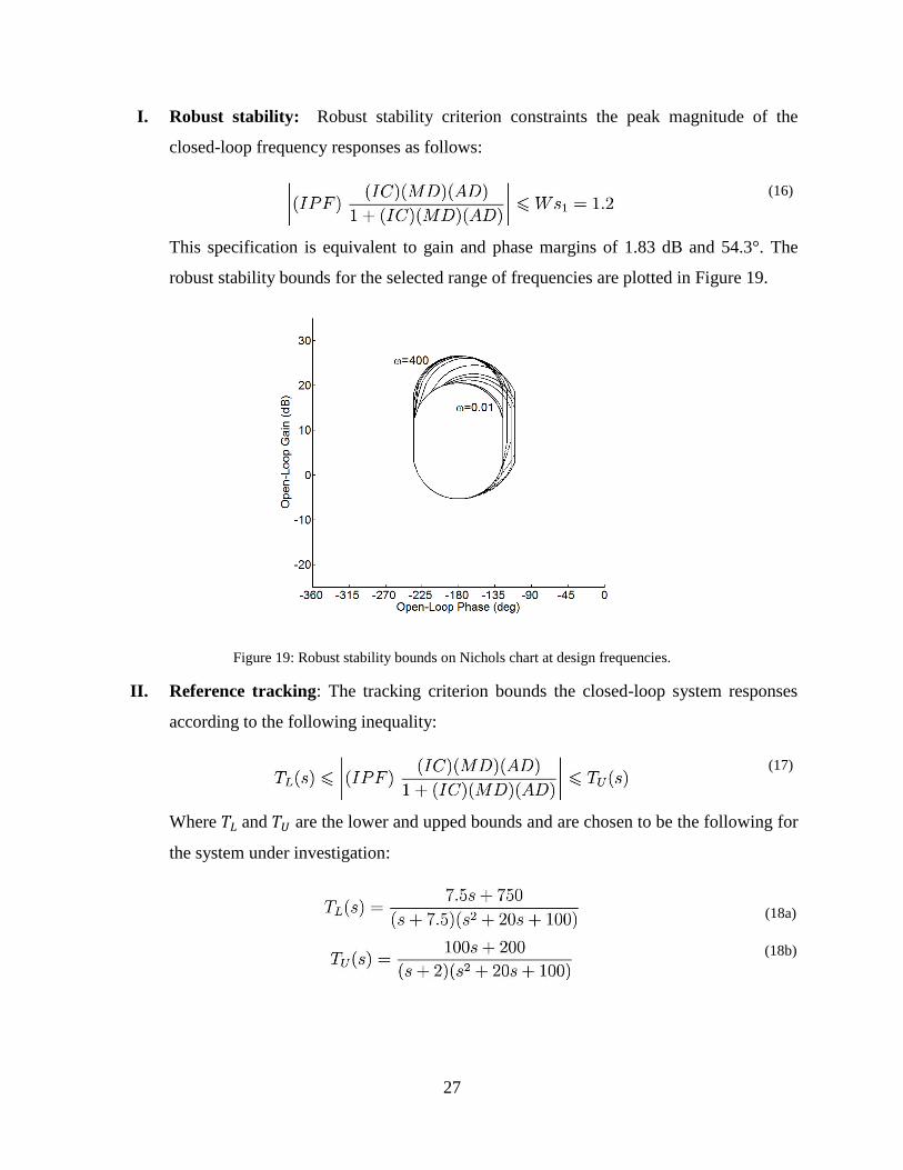
I. Robust stability: Robust stability criterion constraints the peak magnitude of the
closed-loop frequency responses as follows:
(16)
This specification is equivalent to gain and phase margins of 1.83 dB and 54.3°. The
robust stability bounds for the selected range of frequencies are plotted in Figure 19.
Figure 19: Robust stability bounds on Nichols chart at design frequencies.
II. Reference tracking: The tracking criterion bounds the closed-loop system responses
according to the following inequality:
(17)
Where 𝑇𝐿 and 𝑇𝑈 are the lower and upped bounds and are chosen to be the following for
the system under investigation:
(18a)
(18b)
28
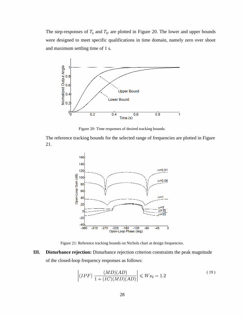
The step-responses of 𝑇𝐿 and 𝑇𝑈 are plotted in Figure 20. The lower and upper bounds
were designed to meet specific qualifications in time domain, namely zero over shoot
and maximum settling time of 1 s.
Figure 20: Time responses of desired tracking bounds.
The reference tracking bounds for the selected range of frequencies are plotted in Figure
21.
Figure 21: Reference tracking bounds on Nichols chart at design frequencies.
III. Disturbance rejection: Disturbance rejection criterion constraints the peak magnitude
of the closed-loop frequency responses as follows:
( 19 )

29
The disturbance rejection bounds for the selected range of frequencies are plotted in
Figure 22.
Figure 22: Disturbance rejection bounds on Nichols chart at design frequencies.
3) Controller and prefilter design: QFT bounds and the nominal loop transfer
function, [(𝐼𝐶)(𝑀𝐷)(𝐴𝐷)], before controller design is plotted in Figure 23 for the selected
range of frequencies.
Figure 23: QFT design bounds and nominal loop transfer function before controller design on Nichols chart at
design frequencies (rad/s).

30
Based on QFT technique, the nominal loop transfer function has to be shaped such that it
lies on or above the tracking bounds and does not enter the stability and disturbance
rejection bounds. The process of shaping the nominal loop transfer function was done by
adding zeros, poles, integrators and differentiators and is called loop shaping. The nominal
loop transfer function after controller design is illustrated in Figure 24. The designed
controller is given by (20).
(20)
Figure 24: QFT design bounds and nominal loop transfer function after controller design on Nichols chart at design
frequencies (rad/s).
To satisfy the tracking specification, a prefilter is designed using Bode plot to put the
closed-loop frequency responses in the desired envelope. The designed prefilter is given
below:
(21)
To check the performance of the proposed controller and prefilter the frequency and time
responses of the linear system are investigated. The frequency responses of the system
before and after the prefilter design are illustrated in Figure 25 for the entire ranges of
uncertainties given in Table 2. The step-responses of the linearized system after controller

31
and prefilter design for the entire ranges of uncertainties given in Table 2 are illustrated in
Figure 26.
Figure 25: Linear system frequency responses using the QFT controller and prefilter for the entire range of
parametric uncertainties given in Table 2.
Figure 26: Linear system step-responses using the QFT controller and prefilter for the entire range of parametric
uncertainties given in Table 2.
As it is observed, the step-responses are within the acceptable envelope of time responses
restricted by the upper and lower bounds defined by (18). Similarly, the frequency
responses are within the acceptable envelope defined by the upper and lower bounds.
4.2 Outer loop fuzzy position controller design
The position of the quadrotor is usually controlled by human operators using radio remote
controls. Considering the fact that rule-based controllers mimic the control behaviour of skilled
operators using IF-THEN fuzzy rules [7], fuzzy logic technique is employed here to design a
position controller for the quadrotor. The position control structure is shown in Figure 13. It

32
consists of three fuzzy logic controllers (FLCs) to control the position of the quadrotor in X, Y
and Z directions using the errors and corresponding rate of errors. The altitude error is (𝑍-𝑍𝑑)
and the rate of altitude error is (�̇�-�̇�𝑑), similarly, the error and the rate of error in X direction are
(𝑋-𝑋𝑑) and (�̇�-�̇�𝑑), respectively. The fuzzy controllers along X and Y directions are identical
due to similar dynamics and parameters. The outputs of the X and Y FLCs are the desired
roll, 𝜃𝑑, and pitch, 𝜑𝑑, angles which are sent to the QFT attitude controllers as depicted in Figure
13. The output of the Z FLC is 𝑈1,𝑑. The membership functions of errors, the rate of errors and
outputs for X and Z controllers are illustrated in Figure 27 to Figure 31. There are five
membership functions for each input of error and output set as Negative Big (NB), Negative
Small (NS), Zero (ZR), Positive Small (PS) and Positive Big (PB). The corresponding
membership functions for the rate of errors are Negative Big (NB), Zero (ZR) and Positive Big
(PB). The proposed fuzzy controllers resemble a PD-type controller. Similar approach was
implemented on quadrotors in [46].
Figure 27: Membership functions for input position error in X and Y directions
Figure 28: Membership function for input position error in Z direction

33
Figure 29: Membership functions for input velocity error in X, Y and Z directions
Figure 30: Membership functions for output attitude angles (𝜃𝑑,𝜑𝑑)
Figure 31: Membership function for output thrust, 𝑈1,𝑑
To generate the output of the controllers, the inputs of errors and the rate of errors are used by
the rules in Table 3 and the output membership functions shown in Figure 30 and Figure 31. The
rules in Table 3 should be read as follows. For instance, if the error is ZR and the rate of error is
PB, then the output is PS. The resulted output should be defuzzified to be used as system control
inputs. The mean-area defuzzification method is chosen [46].

34
Table 3: Table of fuzzy rules to determine fuzzy controller outputs
Error
Rate of Error
NB NS ZR PS PB
NB NB NB NS ZR PS
ZR NB NS ZR PS PB
PB NS ZR PS PB PB
The following example is provided to explain the process of output generation and
defuzzification using the designed fuzzy controllers.
Assume the error in X direction is (𝑋-𝑋𝑑) = 0 m and the rate of error in X direction is (�̇�-�̇�𝑑) =
0.5 m/s. The membership functions and input values are depicted in Figure 32. As it is seen in
this figure, the error is a member of ZR fuzzy set, but the rate of error is a member of both ZR
and PB fuzzy sets. Using Table 3, the rules that are on can be listed as follows:
If error is ZR and the rate of error is ZR then the output angle is ZR. (rule 1)
If error is ZR and the rate of the error is PB then the output force is PS. (rule 2)
These rules are highlighted in Table 3.
Note that since for this design we have maximum of two membership functions overlapping, we
will never have more than four rules on at one time.
Figure 32: Input membership functions with input values.
The recommendations of each rule are calculated independently. Using the minimum to
represent the premise, we are 0.5 certain that rule 1 applies to this situation. Based on rule 1, the
output angle is ZR. The justification for the use of minimum operator to represent the implication
is that “we can be no more certain about our consequent than our premise [53].” The
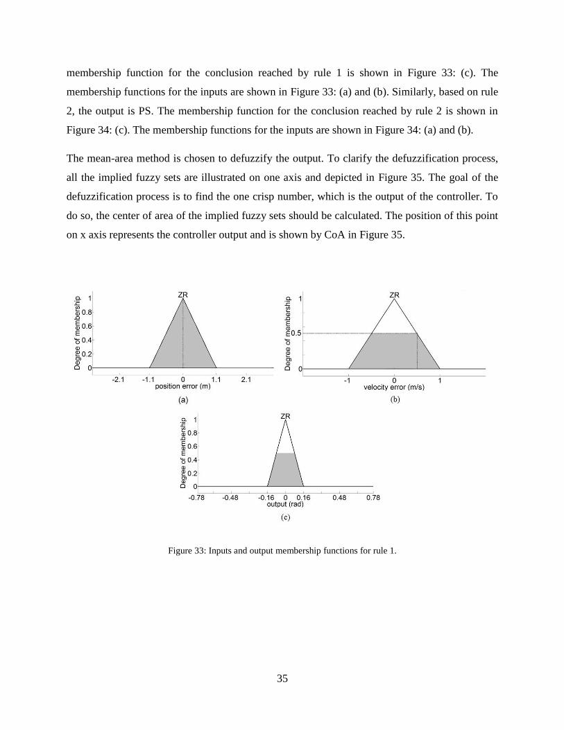
35
membership function for the conclusion reached by rule 1 is shown in Figure 33: (c). The
membership functions for the inputs are shown in Figure 33: (a) and (b). Similarly, based on rule
2, the output is PS. The membership function for the conclusion reached by rule 2 is shown in
Figure 34: (c). The membership functions for the inputs are shown in Figure 34: (a) and (b).
The mean-area method is chosen to defuzzify the output. To clarify the defuzzification process,
all the implied fuzzy sets are illustrated on one axis and depicted in Figure 35. The goal of the
defuzzification process is to find the one crisp number, which is the output of the controller. To
do so, the center of area of the implied fuzzy sets should be calculated. The position of this point
on x axis represents the controller output and is shown by CoA in Figure 35.
Figure 33: Inputs and output membership functions for rule 1.

36
Figure 34: Inputs and output membership functions for rule 2.
Figure 35: Implied fuzzy sets.
4.3 Summary
In Chapter 4, the nested feedback loop control structure for the quadrotor under investigation
was described. QFT design process was presented for a Single-Input Single-Output (SISO) two-
degree-of-freedom control scheme. The inner loop QFT attitude controller design criteria and
procedure were presented. Using the QFT technique, a simple linear fixed-gain attitude
controller was designed considering the external disturbances and plant parametric uncertainties.
The reference tracking performance of the QFT attitude controller was validated by
implementing the designed controller on the linear system. Finally, the outer loop fuzzy position

37
controller design procedure was presented. Now that the QFT-Fuzzy controller design was
addressed, Chapter 5 will attempt to discuss the results of simulation and experimental studies
which were performed using the described controllers.

38
Chapter
5 Results
5.1 Simulation studies
To test the performance of the designed controllers and to tune the fuzzy position controller, a set
of simulation studies were performed. The simulation was based on the full nonlinear equations
of motion and motor dynamics given by (2), (3) and (5), and was implemented under
Simulink®/MATLAB®. Forth-order Runge-Kutta method was used in the simulation with fixed-
step size of 0.001 s. For each simulation study, thirty six simulations, covering the whole ranges
of parametric uncertainties listed in Table 2, were performed.
5.1.1 Open loop system responses
After simulation development, it is vital to validate its accuracy. Consequently, a flight
scenario was performed on the open loop system, to check if the simulation was generating
reasonable results.
Figure 36 shows applied input torques, U2, U3 and U4 and force, U1, to the open loop system.
Considering the fact that the dynamic equations of quadrotor given by (2) do not contain any
damping factor such as air drag, the positive pulse input torques are followed by a negative
pulse to reduce the applied angular accelerations to zero. The assumption that the quadrotor is
moving in vacuum, with no air resistance, is considered to simplify the equations of motion
for controller design phase. In addition, the applied force, 𝑈1, is equal to the weight of the
quadrotor. Based on the applied torques and force, the quadrotor should rotate around its z
axis at 2 s generating yaw angle, followed by a rotation around its x axis at 7 s. The quadrotor
leans as a result of its rotation around x axis, causing it to move in X and Y directions.
Additionally, considering the fact that the net vertical force in Z direction is reduced due to
the new orientation of the quadrotor, the position of the quadrotor in Z direction should start

39
decreasing after 7 s. The output Euler angles and position components are illustrated in Figure
37 and Figure 38, respectively.
Figure 36: Applied input torques and force to open loop system.
Figure 37: Generated Euler angles, due to torques applied to open loop system.
Figure 38: Position alteration, due to torques and force applied to open loop system.

40
As it is observed from Figure 37 and Figure 38, the rotations and movements of the quadrotor
validate the dynamics equations given by (2).
5.1.2 Attitude control
The normalized step-responses of the simulated nonlinear system for thirty six simulations in
tracking various desired step inputs with magnitudes of 5°, 15° and 25° for the entire range of
uncertainties listed in Table 2 are depicted in Figure 39. As it is observed, the step-responses
of the nonlinear system using the QFT controller and prefilter given by (20) and (21) are
within the acceptable envelope despite the approximations were made in linearization process.
Figure 39: Normalized nonlinear system step-responses using the QFT controller and prefilter for entire range of
parametric uncertainties given in Table 2.
5.1.3 Position control
The outer loop fuzzy position controllers discussed in 4.2 were designed and tuned based on
the simulated nonlinear system. The performance of the designed control system was checked
by a set of simulation studies for the entire range of uncertainties listed in Table 2 prior to
experimental studies.
A square-shaped trajectory illustrated in Figure 40 is proposed to investigate the performance
of the QFT-Fuzzy controller. The desired speed of the quadrotor following the trajectory is
2.5 m/s. The desired and actual position of the quadrotor following the trajectory is illustrated
in Figure 44 for thirty six simulations covering the whole range of uncertainties. The desired
and actual Euler angles of the quadrotor during the square-shaped trajectory tracking are
depicted in Figure 41 for a typical simulation. Note that the desired pitch and roll angles, 𝜃𝑑
and 𝜑𝑑 respectively, are the outputs of X and Y fuzzy controllers. (See Figure 13)

41
Figure 40: Square-shaped trajectory in constant 5 m altitude.
Figure 41: Components of desired and actual attitude following the square-shaped trajectory using QFT-Fuzzy
controller for a typical simulation.

42
The corresponding control signals, 𝑈1,𝑑, 𝑈2,𝑑, 𝑈3,𝑑 and 𝑈4,𝑑 are illustrated in Figure 42.
Figure 42: Corresponding control signals following the square-shaped trajectory using QFT-Fuzzy controller for a
typical simulation.

43
Figure 43: Components of desired and actual position following the square-shaped trajectory using QFT-Fuzzy
controller for a typical simulation.
Figure 44: Square-shaped trajectory and followed actual trajectory using QFT-Fuzzy controller for the entire range
of uncertainties listed in Table 2.

44
Based on Figure 39 to Figure 44, the simulation results promise accurate reference tracking
for both QFT and fuzzy controllers.
5.2 Experimental studies
To investigate the performance of the controllers, various experiments were performed. The
experimental platform consists of a 2013 3DR Quad D frame and electronics kit (this includes
the rotors for which kT and kQ were measured), a Pixhawk autopilot system, 3DR UBlox GPS
and compass kit, 3DR 915 MHz telemetry radio system and a Futaba 14SG radio system and
receiver. In attitude section, the step-response and disturbance rejection performance of the QFT
attitude controller were examined first. In these experiments the quadrotor was attached to a
gimbal to constraint its motion in space while allow it to rotate freely around three axes, allowing
up to 45° for the roll and pitch (see Figure 45). The disturbance rejection performance was then
studied in hover state. Finally, the performance of the QFT attitude controller is compared to the
in-built ArduCopter attitude controller during a square-shaped trajectory tracking mission. In
position section, the performance of the QFT-Fuzzy controller was investigated by performing a
square-shaped trajectory tracking. Finally, to further signify the development presented here, the
performance of the designed autopilot is experimentally compared with ArduCopter, an open-
source autopilot code available for Pixhawk flight controller unit.
5.2.1 Attitude control experiments
The first set of experiments was performed to validate the tracking performance proposed in
the QFT design criteria. The normalized step-responses using the QFT controller and prefilter
given by (20) and (21) are depicted in Figure 46 for sixteen experiments in tracking various
desired step inputs with magnitudes of 5°, 15° and 25°. As it is seen in Figure 46, the step-
responses are within the acceptable envelope of time responses restricted by the upper and
lower bounds defined by (18).

45
Figure 45: Custom-made test stand to evaluate designed attitude controller
Figure 46: Experimental normalized step-responses using QFT controller and prefilter in tracking various desired
step inputs having magnitudes of 5°, 15° and 25°.
Next, we investigated the disturbance rejection performance of the quadrotor while it is
attached to the gimbal. The responses of the quadrotor on the gimbal to 20° additive pitch
angle disturbances for six experiments are illustrated in Figure 47. The corresponding control
signals are depicted in Figure 48. The disturbances were applied as follows: a 100 gr weight
was attached to quadrotor frame below the rotor no. 3 by a string with length of 0.63 m and
was held in the plane of rotors. The weight was then let go freely from the plane of rotors in a

46
certain time illustrated by triangles in Figure 47 and Figure 48. The mass was hung for one
second, and then gradually removed within the next one second.
Figure 47: Six experimental responses of quadrotor on a gimbal to 20 additive pitch angle disturbance using the
QFT controller; Disturbance was applied around 2 second as indicated by the triangles.
Figure 48: Corresponding control signals for the quadrotor on a gimbal under 20 additive pitch angle disturbance
using the QFT controller; triangles show the time when disturbance was applied.
As it is seen in Figure 47 the QFT controller is able to attenuate the applied disturbances in
less than a second.
A similar set of experiments was done to investigate the disturbance rejection performance,
while the quadrotor was freely hovering in space. The same disturbances were applied to the
quadrotor in hover state. As it is seen in Figure 49 the disturbances were similarly attenuated
in less than a second.

47
Figure 49: Six experimental responses of the hovering quadrotor to 20 additive pitch angle disturbance using the
QFT controller; Disturbance was applied around 2 second as indicated by the triangles.
Figure 50: Corresponding control signals of the hovering quadrotor under 20 additive pitch angle disturbance using
the QFT controller; triangles illustrate the time when disturbance was applied.
In the final set of experiments for the QFT attitude controller, a square-shaped trajectory
depicted in Figure 51 was tracked to investigate the reference tracking performance of the
QFT controller. To be able to compare the QFT and ArduCopter attitude controllers, the same
ArduCopter position controller was used for outer loop trajectory tracking. The trajectory
generation code works as follows:
The square-shaped trajectory consists of eight waypoints.
There are two different types of waypoints in Figure 51: a) fast waypoints which are
shown by dashed lines and b) slow waypoints which are shown by solid lines.
The desired position point moves with a constant speed equal to 2.5 m/s.
The desired position point stops at slow waypoints and waits for the quadrotor to
reach. After the quadrotor reached the slow waypoint, the desired position point starts

48
moving again with a constant speed equal to 2.5 m/s. The desired position point does
not stop at a fast waypoint. These points are only defined to force the quadrotor to
move back to the trajectory.
Figure 51: Square-shaped trajectory in constant 5 m altitude consists of eight waypoints.
The desired and actual attitude of the quadrotor following the trajectory using the combined
QFT and ArduCopter position controllers for a typical experiment is illustrated in Figure 52.
The same scenario is implemented using the ArduCopter, combined ArduCopter attitude and
position, controllers. A comparison of five experiments for each controller shows an average
mean squared error (MSE) of 0.5818 deg2 and 2.8458 deg
2 for QFT and ArduCopter attitude
controllers respectively. The MSE and error average mean deviation are calculated using the
following formulas:
(22a)
(22b)
Where n is the number of data and m(θ) is the mean of the pitch angle error during each
mission. The detailed MSE and average deviation of each angle for each experiment is
summarized in Table 4.

49
Table 4: Comparison of results of five experiments using QFT and ArduCopter attitude controllers
QFT ArduCopter Attitude
MSE (deg2)
Average
deviation (deg) MSE (deg
2)
Average
deviation (deg)
1st Experiment
Roll 0.4201 0.44 2.1948 1.18
Pitch 0.5279 0.48 2.7924 1.25
2nd
Experiment Roll 0.5580 0.47 3.2373 1.29
Pitch 0.4971 0.48 3.8660 1.55
3rd
Experiment Roll 0.5022 0.44 2.5675 1.21
Pitch 0.5206 0.49 3.8743 1.43
4th
Experiment Roll 0.6360 0.59 3.0890 1.34
Pitch 0.7193 0.62 2.7414 1.25
5th
Experiment Roll 0.7976 0.54 2.0586 1.11
Pitch 0.6391 0.53 2.0365 1.16
Based on the MSE values summarized in Table 4 the reference tracking error of the inner loop
attitude controller reduced by almost 80% using the QFT controller. The error average
deviation is also reduced by 60% using the QFT controller.
Figure 52: Components of desired and actual attitude following the square-shaped trajectory using combined QFT
and ArduCopter position controller for a typical experiment.

50
Figure 53: Corresponding control signals following the square-shaped trajectory using combined QFT and
ArduCopter position controller for a typical experiment.

51
Figure 54: Components of desired and actual position following the square-shaped trajectory using combined QFT
and ArduCopter position controller for a typical experiment.
Figure 55: Square-shaped trajectory and followed actual trajectory using combined QFT and ArduCopter position
controller for a typical experiment.

52
5.2.2 Position control experiments
The same square-shaped trajectory depicted in Figure 51 was followed to investigate the
performance of the QFT-Fuzzy controllers. The desired and actual position of the quadrotor
following the trajectory is illustrated in Figure 59 and Figure 58. The desired and actual
attitude of the quadrotor following the trajectory using the QFT-Fuzzy controllers is shown in
Figure 56 for a typical experiment. The same scenario is implemented for the ArduCopter
controller. A comparison of five experiments for each controller shows an average MSE of
0.8554 m2 and 1.6711 m
2 for QFT-Fuzzy and ArduCopter controllers, respectively. The
detailed MSE in each direction for each experiment is summarized in Table 5. Figure 59 and
Figure 60 show the square-shaped trajectory and the followed actual trajectory using the QFT-
Fuzzy and ArduCopter controllers for five experiments, respectively.
Table 5: Comparison of results of five experiments using QFT-Fuzzy and ArduCopter controllers
QFT-Fuzzy ArduCopter
MSE (m2)
Average
deviation (m) MSE (m
2)
Average
deviation (m)
1st Experiment
Y direction 0.74 0.6 1.76 1.1
X direction 0.64 0.6 1.53 1.0
2nd
Experiment Y direction 1.01 0.7 1.59 1.0
X direction 1.11 0.7 1.57 1.0
3rd
Experiment Y direction 0.90 0.7 1.75 1.1
X direction 0.85 0.7 1.51 1.0
4th
Experiment Y direction 0.91 0.7 1.77 1.0
X direction 0.80 0.6 1.81 1.1
5th
Experiment Y direction 0.77 0.6 2.05 1.2
X direction 0.84 0.7 1.38 1.0
Based on the MSE values summarized in Table 5 the reference tracking error of the controller
illustrated in Figure 13 reduced by almost 50% using QFT-Fuzzy controllers. The error average
deviation is also decreased by 37% using the QFT-Fuzzy controller.

53
Figure 56: Components of desired and actual attitude following the square-shaped trajectory using QFT-Fuzzy
controller for a typical experiment.

54
Figure 57: Corresponding control signals following the square-shaped trajectory using QFT-Fuzzy controller for a
typical experiment.

55
Figure 58: Components of desired and actual position following the square-shaped trajectory using QFT-Fuzzy
controller for a typical experiment.
Figure 59: Square-shaped trajectory and followed trajectory using QFT-Fuzzy controller for five experiments.

56
Figure 60: Square-shaped trajectory and followed trajectory using ArduCopter controller for five experiments.
5.3 Summary
Chapter 5 presented the results of the simulation and experimental studies. The details of the
developed simulation were mentioned. The open loop system responses of the system under
investigation were validated by performing a flight scenario. In addition, the QFT attitude
controller reference tracking performance and the QFT-Fuzzy controller trajectory tracking
performance were studied using the developed simulation. Moreover, five experimental studies
were performed to investigate the performance of the QFT attitude and QFT-Fuzzy controllers;
namely: i) QFT attitude controller reference tracking performance, ii) QFT attitude controller
disturbance rejection performance on a gimbal, iii) QFT attitude controller disturbance rejection
performance in hover condition, iv) QFT attitude controller reference tracking performance
during a trajectory tracking mission, v) QFT-Fuzzy controller trajectory tracking performance.
The MSE and error average deviation of attitude controller reference tracking and the position
controller trajectory tracking were calculated. Finally, the measured values for MSE and error
average deviation using the designed controllers were compared with the corresponding values
of the ArduCopter controllers for several experimental studies. The final results show 50% and
37% reduction of MSE and error average deviation, respectively.

57
Chapter
6 Conclusions
6.1 Overview
In this research, the design and implementation of a simple-to-implement QFT-Fuzzy autopilot
system for a quadrotor was presented. In Chapter 3, equations of motion for a quadrotor were
derived. The system parameters were identified for the commercially-available quadrotor used
for simulation and experimental studies. In Chapter 4, the design criteria and controllers design
procedures were discussed. The proposed QFT attitude controller takes the following criteria into
account: i) system stability ii) disturbance rejection criterion and iii) reference tracking criterion.
The fuzzy logic controllers replaced a human operator to control the position of the quadrotor
and to render a robust trajectory tracking. In Chapter 5, a simulation study was performed to
validate the reference tracking performance of the QFT controller. In addition, the fuzzy position
controller was tuned and its performance was verified using a set of simulations studies. In
Chapter 5, the performance of the designed attitude controller was validated experimentally
which indicates the efficiency of the proposed controller in disturbance rejection and reference
tracking criteria. The results achieved using the QFT-Fuzzy controller in following a square-
shaped trajectory indicate noticeable decreases in MSE for both position and attitude tracking
compared to the results achieved by the in-built ArduCopter autopilot. Namely, 80% MSE
reduction in attitude reference tracking and 50% reduction in position reference tracking.
6.2 Answers to the research questions addressed
The thesis has raised several interesting research questions about attitude and position
controllers, as outlined in Section 1.2.3. This section links the experimental results and
observations to the research questions to provide insight into the answers.

58
1. As seen in Section 5.2.1, the designed QFT attitude controller is able to attenuate the applied
20° additive pitch angle disturbances in less than a second.
2. As seen in Section 5.2.1, the reference tracking MSE using the designed QFT attitude
controller in following a square-shaped trajectory has reduced by 80% compared to
ArduCopter attitude controller. Similarly, the error average deviation has decreased by 60%
using the QFT controller.
3. As seen in Section 5.2.2, the trajectory tracking MSE using the designed QFT-Fuzzy
controller in following a square-shaped trajectory has reduced by 50% compared to
ArduCopter controller. Similarly, the error average deviation has decreased by 37% using the
QFT-Fuzzy controller.
6.3 Contributions
The thesis contributions are:
1. A Simple-to-implement QFT-Fuzzy autopilot system for a quadrotor was designed and
evaluated experimentally.
2. A simulation and a custom-made test stand have been developed to evaluate the performance
of the QFT-Fuzzy controller.
3. The QFT-Fuzzy controller reduced the reference tracking MSE by 50% compared to the
ArduCopter controller.
6.4 Limitations and future work
This work addressed the attitude and position controllers design for a quadrotor. The designed
controller outperforms the ArduCopter controller; yet, some limitations are still present:
1. The fuzzy position controller was tuned using the developed simulation under
Simulink/MATLAB. Considering the fact that the equations of motion do not contain any
damping factor (the quadrotor moves in vacuum), the performance of the fuzzy position
controller could have improved, in terms of trajectory tracking purposes, if it was tuned using
experimental methods.

59
2. Considering the fact that the attitude controller was designed based on the linearized
equations of motion, the quadrotor may not meet the design criteria if it operates far from the
operating point.
Using an efficient set of controllers for a quadrotor, a broad range of applications can be
considered for future work.
GPS alone is not capable to precisely estimate the position of the quadrotor for plenty of
applications. By attaching an onboard camera to the quadrotor and taking advantage of the image
processing algorithms, the relative position of the quadrotor to objects can be determined with
higher accuracy. As a result, plenty of new applications such as, payload pickup and
transportation, landing on small targets, surveillance, roadside litter pickup and agriculture
applications can be investigated.
Another interesting potential for further research is trajectory generation methods. Using these
methods, quadrotors will be able to avoid collisions and obstacles. Taking advantage of these
capabilities, they can be used for plenty of new applications such as construction, payload pickup
and delivery with quadrotor teams. However, trajectory generation methods may lead to fast
maneuvers causing large Euler angles. Consequently, nonlinear control techniques should be
used to guarantee precise trajectory tracking performance far from the hover state.

60
References
[1] A. Ryan and J. K. Hedrick, "A mode-switching path planner for UAV-assisted search and
rescue," in Decision and Control, 2005.
[2] K. Alexis, G. Nikolakopoulos, A. Tzes and L. Dritsas, "Coordination of Helicopter UAVs
for Aerial Forest-Fire Surveillance," in Applications of Intelligent Control to Engineering
Systems, Netherlands, Springer, 2009, pp. 169-193.
[3] J.-H. Kim and S. Sukkarieh, "Airborne Simultaneous Localisation and Map Building," in
Robotics and Automation, Taipei, Taiwan, 2003.
[4] K. Alexis, G. Nikolakopoulos and A. Tzes, "Experimental Constrained Optimal Attitude
Control of a Quadrotor Subject to Wind Disturbances," International Journal of Control,
Automation, and Systems, vol. 7, no. 1, pp. 1289-1302, 2014.
[5] G. M. Hoffmann, H. Huang, S. L. Waslander and C. J. Tomlin, "Precision flight control for
a multi-vehicle quadrotor helicopter testbed," Control Engineering Practice, vol. 19, no. 9,
p. 1023–1036, 2011.
[6] C. H. Houpis, S. J. Rasmussen and M. Garcia-Sanz, Quantitative Feedback Theory:
Fundamentals and Applications, Second Edition, Boca Raton, FL: CRC Press, 2005.
[7] R. Zhang, Y. A. Phillis and V. S. Kouikoglou, Fuzzy Control of Queuing Systems, London :
Springer , 2004 .
[8] "Ardupilot," ArduPilot Dev Team., [Online]. Available:
http://ardupilot.org/copter/index.html. [Accessed 24 3 2016].
[9] "www.3drobotics.com," 3DR, [Online]. Available:
https://s3.amazonaws.com/3dr.production/1232/large/X8DIYCopter.png?1441214901.
[Accessed 21 10 2015].
[10] I. Kroo, F. Prinz, M. Shantz, P. Kunz, G. Fay, S. Cheng, T. Fabian and C. Partridge, "The
Mesicopter: A Miniature Rotorcraft Concept Phase II Interim Report," Stanford University,
2000.
[11] G. Hoffmann, D. Rajnarayan, S. Waslander and D. Dostal, "The Stanford Testbed of
Autonomous Rotorcraft for Multi Agent Control (STARMAC)," in Proc. Digital Avionics
Systems Conference, Salt Lake City, 2004.

61
[12] S. Bouabdallah, "Design and control of quadrotors with application to autonomous flying,"
École Polytechnique Federale de Lausanne, PhD Thesis, Lausanne, 2007.
[13] P. Pounds, "Design, Construction and Control of a Large Quadrotor Micro Air Vehicle,"
Australian National University, PhD Thesis, Canberra, 2007.
[14] N. Guenard, T. Hamel and V. Moreau, "Dynamic modeling and intuitive control strategy for
an ”X4-flyer”," in Proc. International Conference on Control and Automation, Budapest,
2005.
[15] N. Guenard, T. Hamel, V. Moreau and R. Mahony, "Design of a controller allowed the
intuitive control of an X4-flyer," in Robot Control, Santa Cristina Convent, University of
Bologna, Italy, 2006.
[16] S. Park, D. Won, M. Kang, T. Kim, H. Lee and S. Kwon, "RIC(Robust Internal-loop
Compensator) Based Flight Control of a Quad-Rotor Type UAV," in Intelligent Robots and
Systems, 2005.
[17] C. Nicol, C. Macnab and A. Ramirez-Serrano, "Robust adaptive control of a quadrotor
helicopter," Mechatronics, vol. 21, no. 6, pp. 927-938, 2011.
[18] G. B. Kim, T. K. Nguyen, A. Budiyono, J. K. Park, K. J. Yoon and J. Shin, "Design and
Development of a Class of Rotorcraft-based UAV," International Journal of Advanced
Robotic Systems, vol. 10, 2012.
[19] P. Castillo, R. Lozano and A. Dzul, "Stabilization of a mini-rotorcraft having four rotors," in
IEEE/RSJ International Conference on Intelligent Robots and Systems, Sendai, Japan, 2004.
[20] S. L. Waslander and C. Wang, "Wind Disturbance Estimation and Rejection for Quadrotor
Position Control," AIAA Infotech@Aerospace Conference, Seattle, 2009.
[21] J. Escareño, S. Salazar, H. Romero and R. Lozano, "Trajectory Control of a Quadrotor
Subject to 2D Wind Disturbances," Journal of Intelligent & Robotic Systems, vol. 70, no. 1,
pp. 51-63, 2013.
[22] L. Besnard, Y. B. Shtessel and B. Landrum, "Quadrotor vehicle control via sliding mode
controller driven by sliding mode disturbance observer," Journal of the Franklin Institute,
vol. 349, no. 2, p. 658–684, 2012.
[23] K. Alexis, G. Nikolakopoulos and A. Tzes, "Switching model predictive attitude control for
a quadrotor helicopter," Control Engineering Practice, vol. 19, no. 10, p. 1195–1207, 2011.
62
[24] W. Dong, G.-Y. Gu, X. Zhu and H. Ding, "High-performance trajectory tracking control of
a quadrotor with disturbance observer," Sensors and Actuators A: Physical, vol. 211, p. 67–
77, 2014.
[25] D. Mellinger, "Trajectory Generation and Control for Quadrotors," University of
Pennsylvania, PhD Thesis, Philadelphia, 2012.
[26] M. Hehn and R. D'Andrea, "Real-Time Trajectory Generation for Quadrocopters," IEEE
TRANSACTIONS ON ROBOTICS, vol. 31, no. 4, pp. 877 - 892 , 2015.
[27] Y. Bouktir, M. Haddad and T. Chettibi, "Trajectory planning for a quadrotor helicopter," in
Mediterranean Conference on Control and Automation , Ajaccio, 2008.
[28] S. Kim, S. Choi, H. Lee and H. Kim, "Vision-Based Collaborative Lifting Using Quadrotor
UAVs," in Control, Automation and Systems, Seoul, 2014.
[29] G. M. Hoffmann, H. Huang, S. L. Waslander and C. J. Tomlin, "Quadrotor Helicopter
Flight Dynamics and Control: Theory and Experiment," in Navigation and Control
Conference and Exhibit, Hilton Head, South Carolina, 2007.
[30] S. Bouabdallah and R. Siegwart, "Full Control of a Quadrotor," in IEEE/RSJ International
Conference on Intelligent Robots and Systems, San Diego, CA , 2007 .
[31] S. D. Hanford, "A Small Semi-Autonmomous Rotary-Wing Unmanned Air Vehicle," The
Pennsylvania State University, Master of Science Thesis, 2005.
[32] M. Chen, "Formation and flight control of affordable quad-rotor unmanned air vehicles,"
UBC, Master of Science Thesis, Vancouver, 1998.
[33] P. Castillo, A. Dzul and R. Lozano, "Real-Time Stabilization and Tracking of a Four-Rotor
Mini Rotorcraft," Control Systems Technology, vol. 12, no. 4, pp. 510-516, 2004.
[34] A. Tayebi and S. McGilvray, "Attitude Stabilization of a VTOL Quadrotor Aircraft,"
Control Systems Technology, vol. 14, no. 3, pp. 562-571, 2006.
[35] D. Cabecinhas, R. Cunha and C. Silvestre, "Experimental validation of a nonlinear
quadrotor controller with wind disturbance rejection," in European Control Conference
(ECC), Zurich, 2013.
[36] C. Ha, Z. Zuo, F. B. Choi and D. Lee, "Passivity-based adaptive backstepping control of
quadrotor-type UAVs," Robotics and Autonomous Systems, vol. 62, no. 9, p. 1305–1315,
2014.

63
[37] S. Kim, S. Choi and H. J. Kim, "Aerial Manipulation Using a Quadrotor with a Two DOF
Robotic Arm," in Intelligent Robots and Systems (IROS), 2013 IEEE/RSJ International
Conference on, Tokyo, 2013.
[38] P. I. T. M. Das, S. Swami and J. M. Conrad, "An Algorithm for Landing a Quadrotor
Unmanned Aerial Vehicle on an Oscillating Surface," in Southeastcon, 2012 Proceedings of
IEEE, Orlando, FL, 2012.
[39] P. Pounds, R. Mahony, P. Hynes and J. Roberts, "Design of a Four-Rotor Aerial Robot," in
Australasian Conference on Robotics and Automation, Auckland, 2002.
[40] P. Pounds, R. Mahony, J. Gresham, P. Corke and J. M. Roberts, "Towards dynamically-
favourable quad-rotor aerial robots," in Australasian Conference on Robotics & Automation,
Canberra, 2004.
[41] S. Bouabdallah, P. Murrieri and R. Siegwart, "Design and Control of an indoor micro
quadrotor," in IEEE International Conference on Robotics and Automation, 2004.
[42] S. Bouabdallah and R. Siegwart, "Backstepping and Sliding-mode Techniques Applied to an
Indoor Micro Quadrotor," in IEEE International Conference Robotics and Automation,
Barcelona, 2005.
[43] S. Bouabdallah, A. Noth and R. Siegwart, "PID vs LQ Control Techniques Applied to an
Indoor Micro Quadrotor," in IEEE/RSJ International Intelligent Robots and Systems, 2004.
[44] N. Michael, D. Mellinger, Q. Lindsey and V. Kumar, "The GRASP Multiple Micro UAV
Testbed," Robotics & Automation Magazin, vol. 17, no. 3, pp. 56 - 65, 2010.
[45] Q. Lindsey, D. Mellinger and V. Kumar, "Construction with quadrotor teams," Autonomous
Robots, vol. 33, no. 3, pp. 323-336, 2012.
[46] B. Erginer and E. Altuğ, "Design and implementation of a hybrid fuzzy logic controller for a
quadrotor VTOL vehicle," International Journal of Control, Automation and Systems, vol.
10, no. 1, pp. 61-70, 2012.
[47] Y. Xu and C. Tong, "Quantitative Feedback Control of a Quadrotor," in IEEE International
Symposium on Industrial Electronics, Hangzhou, 2012.
[48] M. French, Director, Measuring Mass Moment of Inertia - Brain Waves. [Film]. Purdue
University, 2012.
[49] J. C. Sprott, Chaos and Time-Series Analysis, Oxford, UK: Oxford Univ. Press, 2003.

64
[50] W. Kinsner, "“Fractal and chaos engineering,” Lecture Notes," University of Manitoba,
Winnipeg, 2015.
[51] C. H. Houpis and S. J. Rasmussen, Quantitative Feedback Theory: Fundamentals and
Applications, New York,: Marcel Dekker, Inc., 1999.
[52] C. Borghesani, Y. Chait and O. Yaniv, "The QFT Frequency Domain Control Design
Toolbox," Terasoft, Inc., 2003.
[53] Z. Kovacic and S. Bogdan, Fuzzy Controller Design Theory and Applications, Boca Raton:
CRC Press, 2005.
[54] S. H. Chiew, W. Zhao and T. H. Go, "Swarming Coordination with Robust Control
Lyapunov Function Approach," Journal of Intelligent & Robotic Systems, vol. 78, no. 3, pp.
499-515, 2015.


![Self-positioning of a team of flying smart cameras · oscillation-free quadrotors [5], [6]. However, oscillations are frequent and caused by the nature of the quadrotors’ dynamics.](https://static.fdocuments.in/doc/165x107/5ea35ce76f5e9c01fe0f0698/self-positioning-of-a-team-of-iying-smart-cameras-oscillation-free-quadrotors.jpg)