Towards A Swarm of Agile Micro Quadrotors A Swarm of Agile Micro Quadrotors Alex Kushleyev, Daniel...
8
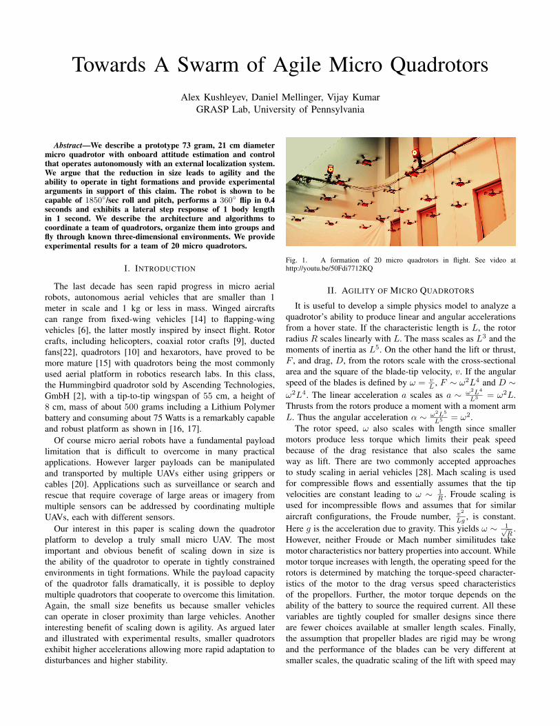
Towards A Swarm of Agile Micro Quadrotors Alex Kushleyev, Daniel Mellinger, Vijay Kumar GRASP Lab, University of Pennsylvania Abstract—We describe a prototype 73 gram, 21 cm diameter micro quadrotor with onboard attitude estimation and control that operates autonomously with an external localization system. We argue that the reduction in size leads to agility and the ability to operate in tight formations and provide experimental arguments in support of this claim. The robot is shown to be capable of 1850 ◦ /sec roll and pitch, performs a 360 ◦ flip in 0.4 seconds and exhibits a lateral step response of 1 body length in 1 second. We describe the architecture and algorithms to coordinate a team of quadrotors, organize them into groups and fly through known three-dimensional environments. We provide experimental results for a team of 20 micro quadrotors. I. I NTRODUCTION The last decade has seen rapid progress in micro aerial robots, autonomous aerial vehicles that are smaller than 1 meter in scale and 1 kg or less in mass. Winged aircrafts can range from fixed-wing vehicles [14] to flapping-wing vehicles [6], the latter mostly inspired by insect flight. Rotor crafts, including helicopters, coaxial rotor crafts [9], ducted fans[22], quadrotors [10] and hexarotors, have proved to be more mature [15] with quadrotors being the most commonly used aerial platform in robotics research labs. In this class, the Hummingbird quadrotor sold by Ascending Technologies, GmbH [2], with a tip-to-tip wingspan of 55 cm, a height of 8 cm, mass of about 500 grams including a Lithium Polymer battery and consuming about 75 Watts is a remarkably capable and robust platform as shown in [16, 17]. Of course micro aerial robots have a fundamental payload limitation that is difficult to overcome in many practical applications. However larger payloads can be manipulated and transported by multiple UAVs either using grippers or cables [20]. Applications such as surveillance or search and rescue that require coverage of large areas or imagery from multiple sensors can be addressed by coordinating multiple UAVs, each with different sensors. Our interest in this paper is scaling down the quadrotor platform to develop a truly small micro UAV. The most important and obvious benefit of scaling down in size is the ability of the quadrotor to operate in tightly constrained environments in tight formations. While the payload capacity of the quadrotor falls dramatically, it is possible to deploy multiple quadrotors that cooperate to overcome this limitation. Again, the small size benefits us because smaller vehicles can operate in closer proximity than large vehicles. Another interesting benefit of scaling down is agility. As argued later and illustrated with experimental results, smaller quadrotors exhibit higher accelerations allowing more rapid adaptation to disturbances and higher stability. Fig. 1. A formation of 20 micro quadrotors in flight. See video at http://youtu.be/50Fdi7712KQ II. AGILITY OF MICRO QUADROTORS It is useful to develop a simple physics model to analyze a quadrotor’s ability to produce linear and angular accelerations from a hover state. If the characteristic length is L, the rotor radius R scales linearly with L. The mass scales as L 3 and the moments of inertia as L 5 . On the other hand the lift or thrust, F , and drag, D, from the rotors scale with the cross-sectional area and the square of the blade-tip velocity, v. If the angular speed of the blades is defined by ω = v L , F ∼ ω 2 L 4 and D ∼ ω 2 L 4 . The linear acceleration a scales as a ∼ ω 2 L 4 L 3 = ω 2 L. Thrusts from the rotors produce a moment with a moment arm L. Thus the angular acceleration α ∼ ω 2 L 5 L 5 = ω 2 . The rotor speed, ω also scales with length since smaller motors produce less torque which limits their peak speed because of the drag resistance that also scales the same way as lift. There are two commonly accepted approaches to study scaling in aerial vehicles [28]. Mach scaling is used for compressible flows and essentially assumes that the tip velocities are constant leading to ω ∼ 1 R . Froude scaling is used for incompressible flows and assumes that for similar aircraft configurations, the Froude number, v 2 Lg , is constant. Here g is the acceleration due to gravity. This yields ω ∼ 1 √ R . However, neither Froude or Mach number similitudes take motor characteristics nor battery properties into account. While motor torque increases with length, the operating speed for the rotors is determined by matching the torque-speed character- istics of the motor to the drag versus speed characteristics of the propellors. Further, the motor torque depends on the ability of the battery to source the required current. All these variables are tightly coupled for smaller designs since there are fewer choices available at smaller length scales. Finally, the assumption that propeller blades are rigid may be wrong and the performance of the blades can be very different at smaller scales, the quadratic scaling of the lift with speed may
Transcript of Towards A Swarm of Agile Micro Quadrotors A Swarm of Agile Micro Quadrotors Alex Kushleyev, Daniel...
Towards A Swarm of Agile Micro QuadrotorsAlex Kushleyev, Daniel Mellinger, Vijay Kumar
GRASP Lab, University of Pennsylvania
Abstract—We describe a prototype 73 gram, 21 cm diametermicro quadrotor with onboard attitude estimation and controlthat operates autonomously with an external localization system.We argue that the reduction in size leads to agility and theability to operate in tight formations and provide experimentalarguments in support of this claim. The robot is shown to becapable of 1850◦/sec roll and pitch, performs a 360◦ flip in 0.4seconds and exhibits a lateral step response of 1 body lengthin 1 second. We describe the architecture and algorithms tocoordinate a team of quadrotors, organize them into groups andfly through known three-dimensional environments. We provideexperimental results for a team of 20 micro quadrotors.
I. INTRODUCTION
The last decade has seen rapid progress in micro aerialrobots, autonomous aerial vehicles that are smaller than 1meter in scale and 1 kg or less in mass. Winged aircraftscan range from fixed-wing vehicles [14] to flapping-wingvehicles [6], the latter mostly inspired by insect flight. Rotorcrafts, including helicopters, coaxial rotor crafts [9], ductedfans[22], quadrotors [10] and hexarotors, have proved to bemore mature [15] with quadrotors being the most commonlyused aerial platform in robotics research labs. In this class,the Hummingbird quadrotor sold by Ascending Technologies,GmbH [2], with a tip-to-tip wingspan of 55 cm, a height of8 cm, mass of about 500 grams including a Lithium Polymerbattery and consuming about 75 Watts is a remarkably capableand robust platform as shown in [16, 17].
Of course micro aerial robots have a fundamental payloadlimitation that is difficult to overcome in many practicalapplications. However larger payloads can be manipulatedand transported by multiple UAVs either using grippers orcables [20]. Applications such as surveillance or search andrescue that require coverage of large areas or imagery frommultiple sensors can be addressed by coordinating multipleUAVs, each with different sensors.
Our interest in this paper is scaling down the quadrotorplatform to develop a truly small micro UAV. The mostimportant and obvious benefit of scaling down in size isthe ability of the quadrotor to operate in tightly constrainedenvironments in tight formations. While the payload capacityof the quadrotor falls dramatically, it is possible to deploymultiple quadrotors that cooperate to overcome this limitation.Again, the small size benefits us because smaller vehiclescan operate in closer proximity than large vehicles. Anotherinteresting benefit of scaling down is agility. As argued laterand illustrated with experimental results, smaller quadrotorsexhibit higher accelerations allowing more rapid adaptation todisturbances and higher stability.
Fig. 1. A formation of 20 micro quadrotors in flight. See video athttp://youtu.be/50Fdi7712KQ
II. AGILITY OF MICRO QUADROTORS
It is useful to develop a simple physics model to analyze aquadrotor’s ability to produce linear and angular accelerationsfrom a hover state. If the characteristic length is L, the rotorradius R scales linearly with L. The mass scales as L3 and themoments of inertia as L5. On the other hand the lift or thrust,F , and drag, D, from the rotors scale with the cross-sectionalarea and the square of the blade-tip velocity, v. If the angularspeed of the blades is defined by ω = v
L , F ∼ ω2L4 and D ∼ω2L4. The linear acceleration a scales as a ∼ ω2L4
L3 = ω2L.Thrusts from the rotors produce a moment with a moment armL. Thus the angular acceleration α ∼ ω2L5
L5 = ω2.The rotor speed, ω also scales with length since smaller
motors produce less torque which limits their peak speedbecause of the drag resistance that also scales the sameway as lift. There are two commonly accepted approachesto study scaling in aerial vehicles [28]. Mach scaling is usedfor compressible flows and essentially assumes that the tipvelocities are constant leading to ω ∼ 1
R . Froude scaling isused for incompressible flows and assumes that for similaraircraft configurations, the Froude number, v2
Lg , is constant.Here g is the acceleration due to gravity. This yields ω ∼ 1√
R.
However, neither Froude or Mach number similitudes takemotor characteristics nor battery properties into account. Whilemotor torque increases with length, the operating speed for therotors is determined by matching the torque-speed character-istics of the motor to the drag versus speed characteristicsof the propellors. Further, the motor torque depends on theability of the battery to source the required current. All thesevariables are tightly coupled for smaller designs since thereare fewer choices available at smaller length scales. Finally,the assumption that propeller blades are rigid may be wrongand the performance of the blades can be very different atsmaller scales, the quadratic scaling of the lift with speed may
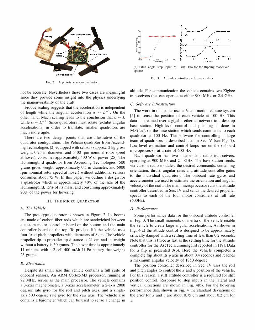
Fig. 2. A prototype micro quadrotor.
not be accurate. Nevertheless these two cases are meaningfulsince they provide some insight into the physics underlyingthe maneuverability of the craft.
Froude scaling suggests that the acceleration is independentof length while the angular acceleration α ∼ L−1. On theother hand, Mach scaling leads to the conclusion that a ∼ Lwhile α ∼ L−2. Since quadrotors must rotate (exhibit angularaccelerations) in order to translate, smaller quadrotors aremuch more agile.
There are two design points that are illustrative of thequadrotor configuration. The Pelican quadrotor from Ascend-ing Technologies [2] equipped with sensors (approx. 2 kg grossweight, 0.75 m diameter, and 5400 rpm nominal rotor speedat hover), consumes approximately 400 W of power [25]. TheHummingbird quadrotor from Ascending Technologies (500grams gross weight, approximately 0.5 m diameter, and 5000rpm nominal rotor speed at hover) without additional sensorsconsumes about 75 W. In this paper, we outline a design fora quadrotor which is approximately 40% of the size of theHummingbird, 15% of its mass, and consuming approximately20% of the power for hovering.
III. THE MICRO QUADROTOR
A. The Vehicle
The prototype quadrotor is shown in Figure 2. Its boomsare made of carbon fiber rods which are sandwiched betweena custom motor controller board on the bottom and the maincontroller board on the top. To produce lift the vehicle usesfour fixed-pitch propellers with diameters of 8 cm. The vehiclepropeller-tip-to-propeller-tip distance is 21 cm and its weightwithout a battery is 50 grams. The hover time is approximately11 minutes with a 2-cell 400 mAh Li-Po battery that weighs23 grams.
B. Electronics
Despite its small size this vehicle contains a full suite ofonboard sensors. An ARM Cortex-M3 processor, running at72 MHz, serves as the main processor. The vehicle containsa 3-axis magnetometer, a 3-axis accelerometer, a 2-axis 2000deg/sec rate gyro for the roll and pitch axes, and a single-axis 500 deg/sec rate gyro for the yaw axis. The vehicle alsocontains a barometer which can be used to sense a change in
−0.1 0 0.1 0.2 0.30
10
20
30
40
50
Pitc
h An
gle
(deg
)
Time (sec)
(a) Pitch angle step input re-sponse
(b) Data for the flipping maneuver
Fig. 3. Attitude controller performance data
altitude. For communication the vehicle contains two Zigbeetransceivers that can operate at either 900 MHz or 2.4 GHz.
C. Software Infrastructure
The work in this paper uses a Vicon motion capture system[5] to sense the position of each vehicle at 100 Hz. Thisdata is streamed over a gigabit ethernet network to a desktopbase station. High-level control and planning is done inMATLAB on the base station which sends commands to eachquadrotor at 100 Hz. The software for controlling a largeteam of quadrotors is described later in Sec. V (see Fig. 7).Low-level estimation and control loops run on the onboardmicroprocessor at a rate of 600 Hz.
Each quadrotor has two independent radio transceivers,operating at 900 MHz and 2.4 GHz. The base station sends,via custom radio modules, the desired commands, containingorientation, thrust, angular rates and attitude controller gainsto the individual quadrotors. The onboard rate gyros andaccelerometer are used to estimate the orientation and angularvelocity of the craft. The main microprocessor runs the attitudecontroller described in Sec. IV and sends the desired propellerspeeds to each of the four motor controllers at full rate(600Hz).
D. Performance
Some performance data for the onboard attitude controllerin Fig. 3. The small moments of inertia of the vehicle enablethe vehicle to create large angular accelerations. As shown inFig. 4(a) the attiude control is designed to be approximatelycritically damped with a settling time of less than 0.2 seconds.Note that this is twice as fast as the settling time for the attitudecontroller for the AscTec Hummingbird reported in [18]. Datafor a flip is presented 3(b). Here the vehicle completes acomplete flip about its y axis in about 0.4 seconds and reachesa maximum angular velocity of 1850 deg/sec.
The position controller described in Sec. IV uses the rolland pitch angles to control the x and y position of the vehicle.For this reason, a stiff attitude controller is a required for stiffposition control. Response to step inputs in the lateral andvertical directions are shown in Fig. 4(b). For the hoveringperformance data shown in Fig. 4 the standard deviations ofthe error for x and y are about 0.75 cm and about 0.2 cm forz.
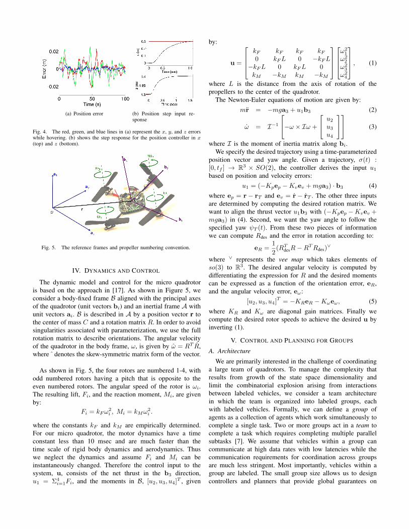
(a) Position error (b) Position step input re-sponse
Fig. 4. The red, green, and blue lines in (a) represent the x, y, and z errorswhile hovering. (b) shows the step response for the position controller in x(top) and z (bottom).
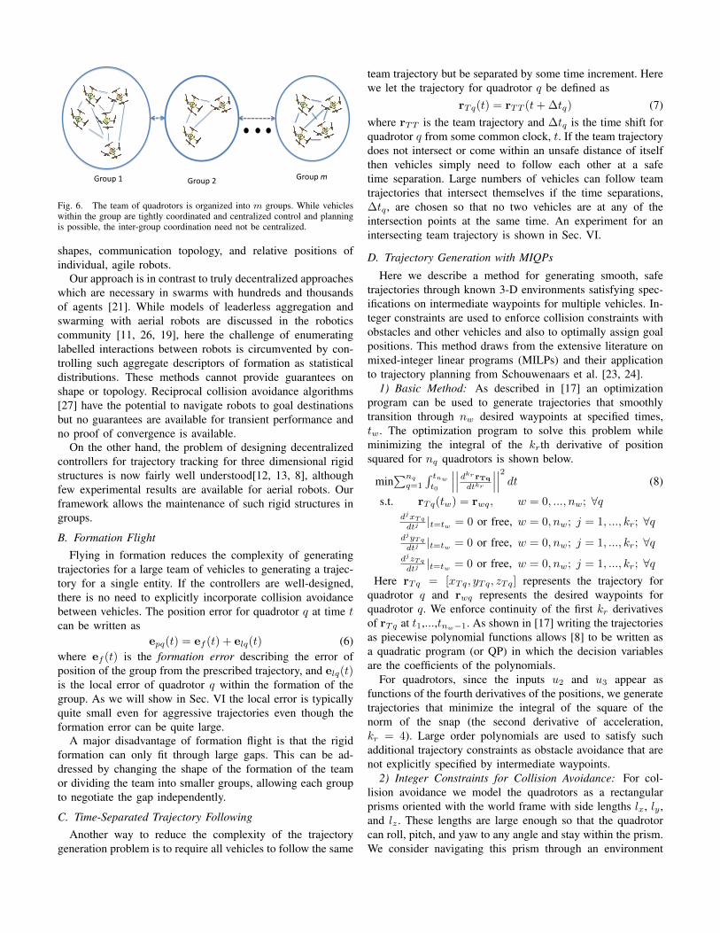
Fig. 5. The reference frames and propeller numbering convention.
IV. DYNAMICS AND CONTROL
The dynamic model and control for the micro quadrotoris based on the approach in [17]. As shown in Figure 5, weconsider a body-fixed frame B aligned with the principal axesof the quadrotor (unit vectors bi) and an inertial frame A withunit vectors ai. B is described in A by a position vector r tothe center of mass C and a rotation matrix R. In order to avoidsingularities associated with parameterization, we use the fullrotation matrix to describe orientations. The angular velocityof the quadrotor in the body frame, ω, is given by ω = RT R,where ˆ denotes the skew-symmetric matrix form of the vector.
As shown in Fig. 5, the four rotors are numbered 1-4, withodd numbered rotors having a pitch that is opposite to theeven numbered rotors. The angular speed of the rotor is ωi.The resulting lift, Fi, and the reaction moment, Mi, are givenby:
Fi = kFω2i , Mi = kMω
2i .
where the constants kF and kM are empirically determined.For our micro quadrotor, the motor dynamics have a timeconstant less than 10 msec and are much faster than thetime scale of rigid body dynamics and aerodynamics. Thuswe neglect the dynamics and assume Fi and Mi can beinstantaneously changed. Therefore the control input to thesystem, u, consists of the net thrust in the b3 direction,u1 = Σ4
i=1Fi, and the moments in B, [u2, u3, u4]T , given
by:
u =
kF kF kF kF0 kFL 0 −kFL
−kFL 0 kFL 0kM −kM kM −kM
ω21
ω22
ω23
ω24
, (1)
where L is the distance from the axis of rotation of thepropellers to the center of the quadrotor.
The Newton-Euler equations of motion are given by:mr = −mga3 + u1b3 (2)
ω = I−1−ω × Iω +
u2u3u4
(3)
where I is the moment of inertia matrix along bi.We specify the desired trajectory using a time-parameterized
position vector and yaw angle. Given a trajectory, σ(t) :[0, tf ] → R3 × SO(2), the controller derives the input u1based on position and velocity errors:
u1 = (−Kpep −Kvev +mga3) · b3 (4)where ep = r − rT and ev = r − rT . The other three inputsare determined by computing the desired rotation matrix. Wewant to align the thrust vector u1b3 with (−Kpep −Kvev +mga3) in (4). Second, we want the yaw angle to follow thespecified yaw ψT (t). From these two pieces of informationwe can compute Rdes and the error in rotation according to:
eR =1
2(RT
desR−RTRdes)∨
where ∨ represents the vee map which takes elements ofso(3) to R3. The desired angular velocity is computed bydifferentiating the expression for R and the desired momentscan be expressed as a function of the orientation error, eR,and the angular velocity error, eω:
[u2, u3, u4]T
= −KReR −Kωeω, (5)where KR and Kω are diagonal gain matrices. Finally wecompute the desired rotor speeds to achieve the desired u byinverting (1).
V. CONTROL AND PLANNING FOR GROUPS
A. Architecture
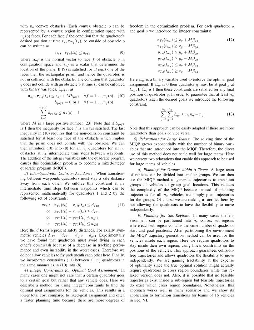
We are primarily interested in the challenge of coordinatinga large team of quadrotors. To manage the complexity thatresults from growth of the state space dimensionality andlimit the combinatorial explosion arising from interactionsbetween labeled vehicles, we consider a team architecturein which the team is organized into labeled groups, eachwith labeled vehicles. Formally, we can define a group ofagents as a collection of agents which work simultaneously tocomplete a single task. Two or more groups act in a team tocomplete a task which requires completing multiple parallelsubtasks [7]. We assume that vehicles within a group cancommunicate at high data rates with low latencies while thecommunication requirements for coordination across groupsare much less stringent. Most importantly, vehicles within agroup are labeled. The small group size allows us to designcontrollers and planners that provide global guarantees on
!"#$%&'& !"#$%&(& !"#$%&!"
Fig. 6. The team of quadrotors is organized into m groups. While vehicleswithin the group are tightly coordinated and centralized control and planningis possible, the inter-group coordination need not be centralized.
shapes, communication topology, and relative positions ofindividual, agile robots.
Our approach is in contrast to truly decentralized approacheswhich are necessary in swarms with hundreds and thousandsof agents [21]. While models of leaderless aggregation andswarming with aerial robots are discussed in the roboticscommunity [11, 26, 19], here the challenge of enumeratinglabelled interactions between robots is circumvented by con-trolling such aggregate descriptors of formation as statisticaldistributions. These methods cannot provide guarantees onshape or topology. Reciprocal collision avoidance algorithms[27] have the potential to navigate robots to goal destinationsbut no guarantees are available for transient performance andno proof of convergence is available.
On the other hand, the problem of designing decentralizedcontrollers for trajectory tracking for three dimensional rigidstructures is now fairly well understood[12, 13, 8], althoughfew experimental results are available for aerial robots. Ourframework allows the maintenance of such rigid structures ingroups.
B. Formation FlightFlying in formation reduces the complexity of generating
trajectories for a large team of vehicles to generating a trajec-tory for a single entity. If the controllers are well-designed,there is no need to explicitly incorporate collision avoidancebetween vehicles. The position error for quadrotor q at time tcan be written as
epq(t) = ef (t) + elq(t) (6)where ef (t) is the formation error describing the error ofposition of the group from the prescribed trajectory, and elq(t)is the local error of quadrotor q within the formation of thegroup. As we will show in Sec. VI the local error is typicallyquite small even for aggressive trajectories even though theformation error can be quite large.
A major disadvantage of formation flight is that the rigidformation can only fit through large gaps. This can be ad-dressed by changing the shape of the formation of the teamor dividing the team into smaller groups, allowing each groupto negotiate the gap independently.
C. Time-Separated Trajectory FollowingAnother way to reduce the complexity of the trajectory
generation problem is to require all vehicles to follow the same
team trajectory but be separated by some time increment. Herewe let the trajectory for quadrotor q be defined as
rTq(t) = rTT (t+ ∆tq) (7)where rTT is the team trajectory and ∆tq is the time shift forquadrotor q from some common clock, t. If the team trajectorydoes not intersect or come within an unsafe distance of itselfthen vehicles simply need to follow each other at a safetime separation. Large numbers of vehicles can follow teamtrajectories that intersect themselves if the time separations,∆tq , are chosen so that no two vehicles are at any of theintersection points at the same time. An experiment for anintersecting team trajectory is shown in Sec. VI.
D. Trajectory Generation with MIQPs
Here we describe a method for generating smooth, safetrajectories through known 3-D environments satisfying spec-ifications on intermediate waypoints for multiple vehicles. In-teger constraints are used to enforce collision constraints withobstacles and other vehicles and also to optimally assign goalpositions. This method draws from the extensive literature onmixed-integer linear programs (MILPs) and their applicationto trajectory planning from Schouwenaars et al. [23, 24].
1) Basic Method: As described in [17] an optimizationprogram can be used to generate trajectories that smoothlytransition through nw desired waypoints at specified times,tw. The optimization program to solve this problem whileminimizing the integral of the krth derivative of positionsquared for nq quadrotors is shown below.
min∑nq
q=1
∫ tnw
t0
∣∣∣∣∣∣dkr rTq
dtkr
∣∣∣∣∣∣2 dt (8)
s.t. rTq(tw) = rwq, w = 0, ..., nw; ∀qdjxTq
dtj |t=tw = 0 or free, w = 0, nw; j = 1, ..., kr; ∀qdjyTq
dtj |t=tw = 0 or free, w = 0, nw; j = 1, ..., kr; ∀qdjzTq
dtj |t=tw = 0 or free, w = 0, nw; j = 1, ..., kr; ∀qHere rTq = [xTq, yTq, zTq] represents the trajectory for
quadrotor q and rwq represents the desired waypoints forquadrotor q. We enforce continuity of the first kr derivativesof rTq at t1,...,tnw−1. As shown in [17] writing the trajectoriesas piecewise polynomial functions allows [8] to be written asa quadratic program (or QP) in which the decision variablesare the coefficients of the polynomials.
For quadrotors, since the inputs u2 and u3 appear asfunctions of the fourth derivatives of the positions, we generatetrajectories that minimize the integral of the square of thenorm of the snap (the second derivative of acceleration,kr = 4). Large order polynomials are used to satisfy suchadditional trajectory constraints as obstacle avoidance that arenot explicitly specified by intermediate waypoints.
2) Integer Constraints for Collision Avoidance: For col-lision avoidance we model the quadrotors as a rectangularprisms oriented with the world frame with side lengths lx, ly ,and lz . These lengths are large enough so that the quadrotorcan roll, pitch, and yaw to any angle and stay within the prism.We consider navigating this prism through an environment
with no convex obstacles. Each convex obstacle o can berepresented by a convex region in configuration space withnf (o) faces. For each face f the condition that the quadrotor’sdesired position at time tk, rTq(tk), be outside of obstacle ocan be written as
nof · rTq(tk) ≤ sof , (9)
where nof is the normal vector to face f of obstacle o inconfiguration space and sof is a scalar that determines thelocation of the plane. If (9) is satisfied for at least one of thefaces then the rectangular prism, and hence the quadrotor, isnot in collision with the obstacle. The condition that quadrotorq does not collide with an obstacle o at time tk can be enforcedwith binary variables, bqofk, as
nof · rTq(tk) ≤ sof +Mbqofk ∀f = 1, ..., nf (o) (10)bqofk = 0 or 1 ∀f = 1, ..., nf (o)
nf (o)∑f=1
bqofk ≤ nf (o)− 1
where M is a large positive number [23]. Note that if bqofkis 1 then the inequality for face f is always satisfied. The lastinequality in (10) requires that the non-collision constraint besatisfied for at least one face of the obstacle which impliesthat the prism does not collide with the obstacle. We canthen introduce (10) into (8) for all nq quadrotors for all noobstacles at nk intermediate time steps between waypoints.The addition of the integer variables into the quadratic programcauses this optimization problem to become a mixed-integerquadratic program (MIQP).
3) Inter-Quadrotor Collision Avoidance: When transition-ing between waypoints quadrotors must stay a safe distanceaway from each other. We enforce this constraint at nkintermediate time steps between waypoints which can berepresented mathematically for quadrotors 1 and 2 by thefollowing set of constraints:
∀tk : xT1(tk)− xT2(tk) ≤ dx12 (11)or xT2(tk)− xT1(tk) ≤ dx21or yT1(tk)− yT2(tk) ≤ dy12or yT2(tk)− yT1(tk) ≤ dy21
Here the d terms represent safety distances. For axially sym-metric vehicles dx12 = dx21 = dy12 = dy21. Experimentallywe have found that quadrotors must avoid flying in eachother’s downwash because of a decrease in tracking perfor-mance and even instability in the worst cases. Therefore wedo not allow vehicles to fly underneath each other here. Finally,we incorporate constraints (11) between all nq quadrotors inthe same manner as in (10) into (8).
4) Integer Constraints for Optimal Goal Assignment: Inmany cases one might not care that a certain quadrotor goesto a certain goal but rather that any vehicle does. Here wedescribe a method for using integer constraints to find theoptimal goal assignments for the vehicles. This results in alower total cost compared to fixed-goal assignment and oftena faster planning time because there are more degrees of
freedom in the optimization problem. For each quadrotor qand goal g we introduce the integer constraints:
xTq(tnw) ≤ xg +Mβqg (12)
xTq(tnw) ≥ xg −Mβqg
yTq(tnw) ≤ yg +Mβqg
yTq(tnw) ≥ yg −Mβqg
zTq(tnw) ≤ zg +Mβqg
zTq(tnw) ≥ zg −Mβqg
Here βqg is a binary variable used to enforce the optimal goalassignment. If βqg is 0 then quadrotor q must be at goal g attnw
. If βqg is 1 then these constraints are satisfied for any finalposition of quadrotor q. In order to guaruntee that at least ngquadrotors reach the desired goals we introduce the followingconstraint.
nq∑q=1
ng∑g=1
βqg ≤ ngnq − ng (13)
Note that this approach can be easily adapted if there are morequadrotors than goals or vice versa.
5) Relaxations for Large Teams: The solving time of theMIQP grows exponentially with the number of binary vari-ables that are introduced into the MIQP. Therefore, the directuse of this method does not scale well for large teams. Herewe present two relaxations that enable this approach to be usedfor large teams of vehicles.
a) Planning for Groups within a Team: A large teamof vehicles can be divided into smaller groups. We can thenuse the MIQP method to generate trajectories to transitiongroups of vehicles to group goal locations. This reducesthe complexity of the MIQP because instead of planningtrajectories for all nq vehicles we simply plan trajectoriesfor the groups. Of course we are making a sacrifice here bynot allowing the quadrotors to have the flexibility to moveindependently.
b) Planning for Sub-Regions: In many cases the en-vironment can be partitioned into nr convex sub-regionswhere each sub-region contains the same number of quadrotorstart and goal positions. After partitioning the environmentthe MIQP trajectory generation method can be used for thevehicles inside each region. Here we require quadrotors tostay inside their own regions using linear constraints on thepositions of the vehicles. This approach guarantees collision-free trajectories and allows quadrotors the flexibility to moveindependently. We are gaining tractability at the expenseof optimality since the true optimal solution might actuallyrequire quadrotors to cross region boundaries while this re-laxed version does not. Also, it is possible that no feasibletrajectories exist inside a sub-region but feasible trajectoriesdo exist which cross region boundaries. Nonetheless, thisapproach works well in many scenarios and we show itsapplication to formation transitions for teams of 16 vehiclesin Sec. VI.

Fig. 7. Software Infrastructure
VI. EXPERIMENTAL RESULTS
A. Software Infrastructure for Groups
Our architecture (Sec. V-A) is important for a very practicalreason. For a large team of quadrotors it is impossible to runa single loop that can receive all the Vicon data, compute thecommands, and communicate with each quadrotor at a fastenough rate. As shown in Fig. 7, each group is controlledby a dedicated software node, running in an independentthread. These control nodes receive vehicle pose data froma special Vicon node via shared memory. The node connectsto the Vicon tracking system, receives marker positions foreach subject, performs a 6D pose fit to the marker dataand additional processing for velocity estimation. Finally, theprocessed pose estimates are published to the shared memoryusing the Boost C++ library [3]. Shared memory is the fastestmethod of inter-process communication, which ensures thelowest latency of the time-critical data.
The control nodes, implemented in Matlab, read the posedata directly from shared memory and compute the com-manded orientation and net thrusts for several quadrotors basedon the controller described in IV. For non-time-critical datasharing we use Inter Process Communication (IPC) [4]. Forexample, high-level user commands such as desired vehiclepositions are sent to a planner which computes the trajectoriesfor the vehicles which are sent to the Matlab control nodes viaIPC. IPC provides flexible message passing and uses TCP/IPsockets to send data between processes.
Each Matlab control node is associated with a radio modulecontaining a 900 MHz and 2.4 GHz Zigbee transceivers, whichis used to communicate with all the vehicles in its group.The radio module sends control commands to several vehicles,up to five in this work. Each vehicle operates on a separatechannel and the radio module hops between the frequenciesfor each quadrotor, sending out commands to each vehicle at100 Hz. The radio modules can also simultaneously receivehigh bandwidth feedback from the vehicles, making use of thetwo independent transceivers.
B. Formation Flight
In Fig. 8 we present data for a team of four quadrotorsfollowing a trajectory as a formation. The group formationerror is significantly larger the the local error. The local x andy errors are always less than 3 cm while the formation x erroris as large 11 cm. This data is representative of all formationtrajectory following data because all vehicles are nominally
(a) Top view (b) Error time histories
Fig. 8. Formation following for a 4 quadrotor trajectory. In (a) the coloredlines represent the desired trajecotories for each of the four vehicles and theblack lines represent the actual trajecotries. The errors are shown in (b). Herethe black line represents the formation error, ef (t), from the desired trajectoryand the colored lines represent the local errors, eli(t), for each quadrotor.
(a) Error Data (b) Time-Separated TrajectoryFollowing
Fig. 9. Part (a) shows the Average Standard Deviation for x, y, and z (shownin red, green and blue respectively) for 20 quadrotors in a grid formation. In(b) we show 16 quadrotors following a figure eight pattern. See the video athttp://youtu.be/50Fdi7712KQ
the same and are running the same controller with the samegains. Therefore, even though the deviation from the desiredtrajectory may be large, the relative position error within thegroup is small.
In Fig. 9(a) we show average error data for 20 vehiclesflying in the grid formation shown in Fig. 1. For this exper-iment the vehicles were controlled to hover at a height of1.3 meters for at least 30 seconds at several quadrotor-center-to-quadrotor-center grid spacing distances. The air disturbancecreated from the downwash of all 20 vehicles is significant andcauses the tracking performance to be worse for any vehiclein this formation than for an individual vehicle in still air aspresented in 4. However, as shown in Fig. 9(a), the separationdistance did not have any affect on the hovering performance.Note that at 35 cm grid spacing the nominal distance betweenpropeller tips is about 14 cm.
C. Time-Separated Trajectory Following
In Fig. 9(b) we show a team of 16 vehicles following acyclic figure eight pattern. The time to complete the entirecycle is tc and the vehicles are equally spaced in time alongthe trajectory at time increments of tc
16 . In order to guarunteecollision-free trajectories at the intersection, vehicles spend1532 tc in one loop of the trajectory and 17
32 tc in the other.
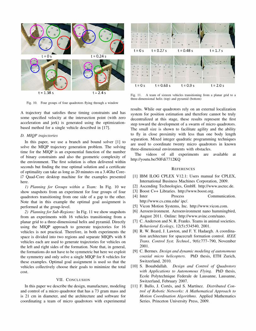
Fig. 10. Four groups of four quadrotors flying through a window
A trajectory that satisfies these timing constraints and hassome specified velocity at the intersection point (with zeroacceleration and jerk) is generated using the optimization-based method for a single vehicle described in [17].
D. MIQP trajectories
In this paper, we use a branch and bound solver [1] tosolve the MIQP trajectory generation problem. The solvingtime for the MIQP is an exponential function of the numberof binary constraints and also the geometric complexity ofthe environment. The first solution is often delivered withinseconds but finding the true optimal solution and a certificateof optimality can take as long as 20 minutes on a 3.4Ghz Core-i7 Quad-Core desktop machine for the examples presentedhere.
1) Planning for Groups within a Team: In Fig. 10 weshow snapshots from an experiment for four groups of fourquadrotors transitioning from one side of a gap to the other.Note that in this example the optimal goal assignment isperformed at the group-level.
2) Planning for Sub-Regions: In Fig. 11 we show snapshotsfrom an experiments with 16 vehicles transitioning from aplanar grid to a three-dimensional helix and pyramid. Directlyusing the MIQP approach to generate trajectories for 16vehicles is not practical. Therefore, in both experiments thespace is divided into two regions and separate MIQPs with 8vehicles each are used to generate trajectories for vehicles onthe left and right sides of the formation. Note that, in general,the formations do not have to be symmetric but here we exploitthe symmetry and only solve a single MIQP for 8 vehicles forthese examples. Optimal goal assignment is used so that thevehicles collectively choose their goals to minimize the totalcost.
VII. CONCLUSION
In this paper we describe the design, manufacture, modelingand control of a micro quadrotor that has a 73 gram mass andis 21 cm in diameter, and the architecture and software forcoordinating a team of micro quadrotors with experimental
Fig. 11. A team of sixteen vehicles transitioning from a planar grid to athree-dimensional helix (top) and pyramid (bottom)
results. While our quadrotors rely on an external localizationsystem for position estimation and therefore cannot be trulydecentralized at this stage, these results represent the firststep toward the development of a swarm of micro quadrotors.The small size is shown to facilitate agility and the abilityto fly in close proximity with less than one body lengthseparation. Mixed integer quadratic programming techniquesare used to coordinate twenty micro quadrotors in knownthree-dimensional environments with obstacles.
The videos of all experiments are available athttp://youtu.be/50Fdi7712KQ
REFERENCES
[1] IBM ILOG CPLEX V12.1: Users manual for CPLEX,International Business Machines Corporation, 2009.
[2] Ascending Technologies, GmbH. http://www.asctec.de.[3] Boost C++ Libraries. http://www.boost.org.[4] Inter Process Communication.
http://www.cs.cmu.edu/ ipc/.[5] Vicon Motion Systems, Inc. http://www.vicon.com.[6] Aeroenvironment. Aeroenvironment nano hummingbird,
August 2011. Online: http://www.avinc.com/nano.[7] C. Anderson and N. R. Franks. Teams in animal societies.
Behavioral Ecology, 12(5):534540, 2001.[8] R. W. Beard, J. Lawton, and F. Y. Hadaegh. A coordina-
tion architecture for spacecraft formation control. IEEETrans. Control Syst. Technol., 9(6):777–790, November2001.
[9] C. Bermes. Design and dynamic modeling of autonomouscoaxial micro helicopters. PhD thesis, ETH Zurich,Switzerland, 2010.
[10] S. Bouabdallah. Design and Control of Quadrotorswith Applications to Autonomous Flying. PhD thesis,Ecole Polytechnique Federale de Lausanne, Lausanne,Switzerland, February 2007.
[11] F. Bullo, J. Cortes, and S. Martınez. Distributed Con-trol of Robotic Networks: A Mathematical Approach toMotion Coordination Algorithms. Applied MathematicsSeries. Princeton University Press, 2009.
[12] J. P. Desai, J. P. Ostrowski, and V. Kumar. Modeling andcontrol of formations of nonholonomic mobile robots.IEEE Trans. Robot., 17(6):905–908, December 2001.
[13] M. Egerstedt and X. Hu. Formation constrained multi-agent control. IEEE Trans. Robot. Autom., 17(6):947–951, December 2001.
[14] Dario Floreano, Jean-Christophe Zufferey, Adam Klap-tocz, Jrg Markus Germann, and Mirko Kovac. Aerial Lo-comotion in Cluttered Environments. In Proceedings ofthe 15th International Symposium on Robotics Research,2011.
[15] V. Kumar and N. Michael. Opportunities and challengeswith autonomous micro aerial vehicles. In InternationalSymposium on Robotics Research, 2011.
[16] S. Lupashin, A. Schollig, M. Sherback, and R. D’Andrea.A simple learning strategy for high-speed quadrocoptermulti-flips. In Proc. of the IEEE Intl. Conf. on Robot. andAutom., pages 1642–1648, Anchorage, AK, May 2010.
[17] D. Mellinger and V. Kumar. Minimum snap trajectorygeneration and control for quadrotors. In Proc. of theIEEE Intl. Conf. on Robot. and Autom., pages 2520–2525, Shanghai, China, May 2011.
[18] D. Mellinger, N. Michael, and V. Kumar. Trajectorygeneration and control for precise aggressive maneuvers.In Int. Symposium on Experimental Robotics, December2010.
[19] N. Michael and V. Kumar. Control of ensembles of aerialrobots. Proc. of the IEEE, 99(9):1587–1602, September2011.
[20] N. Michael, J. Fink, and V. Kumar. Cooperative ma-nipulation and transportation with aerial robots. Auton.Robots, 30(1):73–86, January 2011.
[21] J. Parrish and W. Hamner, editors. Animal Groups inThree Dimensions. Cambridge University Press, NewYork, 1997.
[22] D. Pines and F. Bohorquez. Challenges facing futuremicro air vehicle development. AIAA J. of Aircraft, 43(2):290–305, 2006.
[23] Tom Schouwenaars, Bart DeMoor, Eric Feron, andJonathan How. Mixed integer programming for multi-vehicle path planning. In European Control Conference,pages 2603–2608, 2001.
[24] Tom Schouwenaars, Andrew Stubbs, James Paduano, andEric Feron. Multi-vehicle path planning for non-line ofsight communication. In American Control Conference,2006.
[25] S. Shen, N. Michael, and V. Kumar. Autonomousmulti-floor indoor navigation with a computationallyconstrained MAV. In Proc. of the IEEE Intl. Conf. onRobot. and Autom., pages 20–25, Shanghai, China, May2011.
[26] H. Tanner, A. Jadbabaie, and G. J. Pappas. Flockingin fixed and switching networks. IEEE Trans. Autom.Control, 52(5):863–868, May 2007.
[27] Jur van den Berg, Stephen J. Guy, Ming C. Lin, andDinesh Manocha. Reciprocal n-body collision avoidance.
In INTERNATIONAL SYMPOSIUM ON ROBOTICS RE-SEARCH, 2009.
[28] C. H. Wolowicz, J. S. Bowman, and W. P. Gilbert. Simil-itude requirements and scaling relationships as applied tomodel testing. Technical report, NASA, August 1979.