ATTACHMENT 2 – CONSTRUCTION GUIDE SPECIFICATIONS …
27
A1-1 ATTACHMENT 2 – CONSTRUCTION GUIDE SPECIFICATIONS FOR HOT ASPHALT CHIP SEALS “These Guide Specifications are the recommendation of the research for NCHRP Project 14-37 that was conducted by Shuler Consultants, LLC. The Guide Specifications have not been approved by NCHRP or any AASHTO committee; nor have they been formally accepted for the AASHTO specifications”.
Transcript of ATTACHMENT 2 – CONSTRUCTION GUIDE SPECIFICATIONS …
A1-1
ATTACHMENT 2 – CONSTRUCTION GUIDE SPECIFICATIONS FOR HOT ASPHALT CHIP SEALS
“These Guide Specifications are the recommendation of the research for NCHRP Project 14-37 that was conducted by Shuler Consultants, LLC. The Guide Specifications have not been approved by NCHRP or
any AASHTO committee; nor have they been formally accepted for the AASHTO specifications”.

Attachment 2 Hot Asphalt Chip Seal
A2-2
SECTION 407 HOT APPLIED CHIP SEAL
407.01 Description This guide specification is intended to provide information needed for owners or contractors to construct hot applied asphalt chip seals. A hot applied asphalt chip seal is the application of hot applied asphalt binder, followed immediately by an application of a single layer of pre-coated aggregate chips.
This guide specification refers to quality requirements for materials and a design method for chip seals available in other AASHTO documents. However, the main purpose is to provide guidance for the construction of hot applied asphalt chip seals applied in one layer.
Commentaries are included within the text of the Guide in places where added emphasis is needed to explain the section being discussed or when there are options to be considered by the user of the Guide, or, as sources of additional information. An example follows: Commentary This Guide covers construction of single application chip seals. If this process is repeated with another application of hot asphalt and another layer of cover aggregate, the process is known as a double chip seal. A triple chip seal would require yet another application of hot asphalt and cover aggregate. Other terms have been used referring to chip seals such as ‘seal coat’, ‘surface treatment’, ‘surface seal’, ‘surface dressing’, ‘sprayed seal’, and others. Sometimes, a fog seal is applied over the completed chip seal.
Attachment 2 Hot Asphalt Chip Seal
A2-3
A. Referenced Documents
1. AASHTO Standards:
M 140, Emulsified Asphalt for fog seal
AASHTO M 320, Standard Specification for Performance-Graded Asphalt Binder.
M-332, Standard Specification for Performance-Graded Asphalt Binder Using Multiple Stress Creep Recovery (MSCR) Test
T 27, Sieve Analysis of Fine and Coarse Aggregates
R-66, Sampling Bituminous Materials
T 96, Resistance to Degradation of Small-Size Coarse Aggregate by Abrasion and Impact in the Los Angeles Machine
T 301, Elastic Recovery Test of Asphalt Materials by Means of a Ductilometer
T 335, Standard Method of Test for Determining the Percentage of Fracture in Coarse Aggregate
2. ASTM Standards:
D 5624, Standard Practice for Determining the Transverse-Aggregate Spread Rate for Surface Treatment Applications
D 6114, Specification for Asphalt Rubber Binder
D 7564, Standard practice for Construction of Asphalt Rubber Cape Seal
D 7741, Standard Test Method of Apparent Viscosity of Asphalt Rubber or other Asphalt Binders by Using a Rotational Hand Held Viscometer
3. Other:
Federal Lands Highway, FLH T508, Flakiness Index Value
B. Terminology
Three broad classes of binders are used in hot applied chip seals. They include asphalt rubber, rubber modified asphalt, and performance graded binders. The latter two are PG graded.
1. Asphalt-Rubber Binder
a. a blend of coarse crumb rubber and an asphalt binder, meeting the requirements of ASTM D-6114. The binder must include at least 15% crumb rubber and can be as high as 22%.
Attachment 2 Hot Asphalt Chip Seal
A2-4
2. Rubber Modified Asphalt a. a blend of fine rubber and an asphalt binder mixed at an asphalt terminal.
The binder may also include polymers. This product is also referred to as a terminal blend. This product includes a minimum of 5% crumb rubber, but can contain as much as 18%. There is no national specification for these products
3. Performance Graded Hot Applied Binders
a. these binders shall meet the requirements of AASHTO M 320. An unmodified or a modified binder could be used in a chip seal application.
4. Emulsions for fog seals, if used
a. CSS-1h – a cationic emulsified asphalt that is slow setting and has a residual binder residue with lower penetration than CSS-1.
b. SS-1h – an anionic emulsified asphalt that is slow setting and has a residual binder residue with lower penetration than SS-1.
407.02 MATERIAL
A. Asphalt Binder
1. Asphalt Rubber Binder– This shall meet all the requirements of ASTM D6114. It is a combination of: Asphalt binder, Asphalt modifier, and Crumb Rubber Modifier (CRM). If used, the asphalt modifier (or extender oil) shall be between 2.5 to 6.0 percent by weight of the asphalt binder in the asphalt-rubber binder.
Commentary The California specification for CRM must be 76 ± 2 percent by weight scrap tire crumb rubber and 24 ± 2 percent by weight high natural crumb rubber (high nat.). The asphalt-rubber binder supplier determines the exact percentage of the extender oil and the CRM.
Attachment 2 Hot Asphalt Chip Seal
A2-5
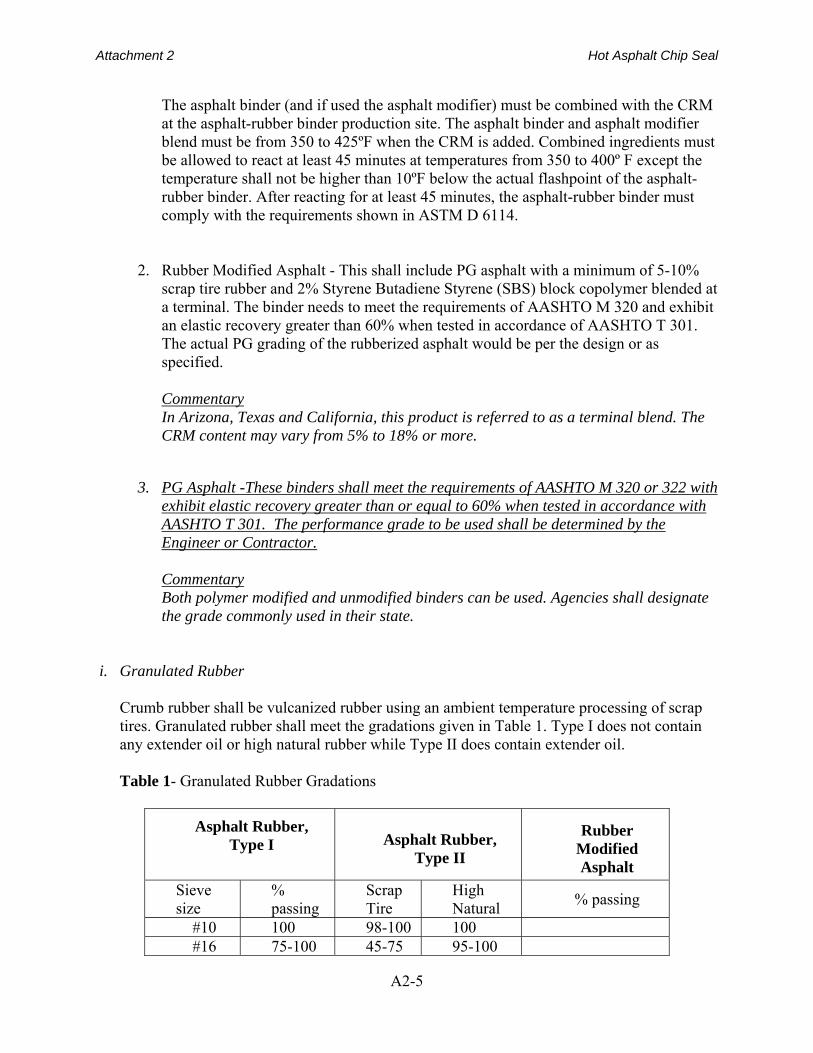
The asphalt binder (and if used the asphalt modifier) must be combined with the CRM at the asphalt-rubber binder production site. The asphalt binder and asphalt modifier blend must be from 350 to 425ºF when the CRM is added. Combined ingredients must be allowed to react at least 45 minutes at temperatures from 350 to 400º F except the temperature shall not be higher than 10ºF below the actual flashpoint of the asphalt-rubber binder. After reacting for at least 45 minutes, the asphalt-rubber binder must comply with the requirements shown in ASTM D 6114.
2. Rubber Modified Asphalt - This shall include PG asphalt with a minimum of 5-10%
scrap tire rubber and 2% Styrene Butadiene Styrene (SBS) block copolymer blended at a terminal. The binder needs to meet the requirements of AASHTO M 320 and exhibit an elastic recovery greater than 60% when tested in accordance of AASHTO T 301. The actual PG grading of the rubberized asphalt would be per the design or as specified. Commentary In Arizona, Texas and California, this product is referred to as a terminal blend. The CRM content may vary from 5% to 18% or more.
3. PG Asphalt -These binders shall meet the requirements of AASHTO M 320 or 322 with
exhibit elastic recovery greater than or equal to 60% when tested in accordance with AASHTO T 301. The performance grade to be used shall be determined by the Engineer or Contractor.
Commentary Both polymer modified and unmodified binders can be used. Agencies shall designate the grade commonly used in their state.
i. Granulated Rubber
Crumb rubber shall be vulcanized rubber using an ambient temperature processing of scrap tires. Granulated rubber shall meet the gradations given in Table 1. Type I does not contain any extender oil or high natural rubber while Type II does contain extender oil.
Table 1- Granulated Rubber Gradations
Asphalt Rubber, Type I
Asphalt Rubber, Type II
Rubber Modified Asphalt
Sieve size
% passing
Scrap Tire
High Natural
% passing
#10 100 98-100 100 #16 75-100 45-75 95-100
Attachment 2 Hot Asphalt Chip Seal
A2-6
#30 30-60 2-20 35-85 100 #50 5-30 0-2 10-30 #200 0-5 0 0-1 0-10
The use of rubber from multiple sources is acceptable provided that the overall blend of
rubber meets the specified gradation. Certification of the gradation and quality of the rubber shall be provided by the rubber supplier.
Commentary The gradations used vary between states. These are guides that should be used if a state has not used hot applied chip seals. Type I is used in Arizona and Type II is used in California. Type II contains extender oils and contains 25% high natural and 75% scrap rubber.
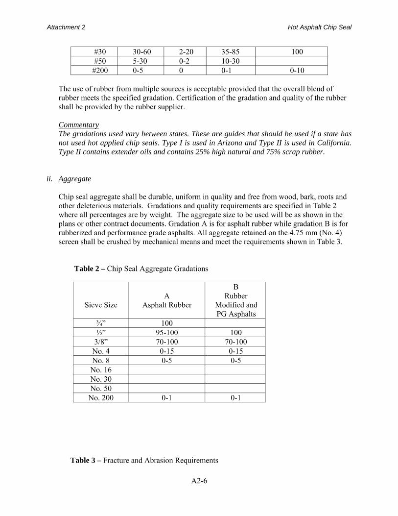
ii. Aggregate Chip seal aggregate shall be durable, uniform in quality and free from wood, bark, roots and
other deleterious materials. Gradations and quality requirements are specified in Table 2 where all percentages are by weight. The aggregate size to be used will be as shown in the plans or other contract documents. Gradation A is for asphalt rubber while gradation B is for rubberized and performance grade asphalts. All aggregate retained on the 4.75 mm (No. 4) screen shall be crushed by mechanical means and meet the requirements shown in Table 3.
Table 2 – Chip Seal Aggregate Gradations
Sieve Size
A
Asphalt Rubber
B Rubber
Modified and PG Asphalts
¾” 100 ½” 95-100 100
3/8” 70-100 70-100 No. 4 0-15 0-15 No. 8 0-5 0-5 No. 16 No. 30 No. 50 No. 200 0-1 0-1
Table 3 – Fracture and Abrasion Requirements
Attachment 2 Hot Asphalt Chip Seal
A2-7
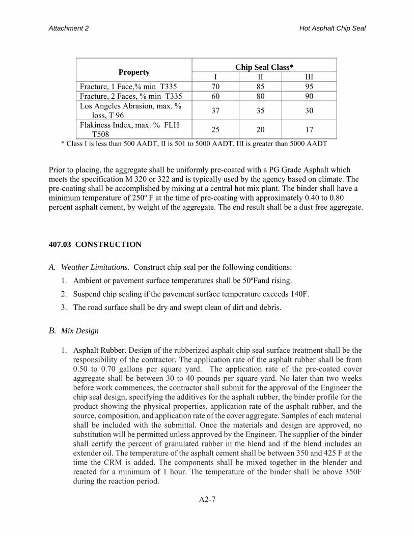
Property Chip Seal Class*
I II III Fracture, 1 Face,% min T335 70 85 95 Fracture, 2 Faces, % min T335 60 80 90 Los Angeles Abrasion, max. %
loss, T 96 37 35 30
Flakiness Index, max. % FLH T508
25 20 17
* Class I is less than 500 AADT, II is 501 to 5000 AADT, III is greater than 5000 AADT Prior to placing, the aggregate shall be uniformly pre-coated with a PG Grade Asphalt which meets the specification M 320 or 322 and is typically used by the agency based on climate. The pre-coating shall be accomplished by mixing at a central hot mix plant. The binder shall have a minimum temperature of 250º F at the time of pre-coating with approximately 0.40 to 0.80 percent asphalt cement, by weight of the aggregate. The end result shall be a dust free aggregate. 407.03 CONSTRUCTION
A. Weather Limitations. Construct chip seal per the following conditions:
1. Ambient or pavement surface temperatures shall be 50ºFand rising.
2. Suspend chip sealing if the pavement surface temperature exceeds 140F.
3. The road surface shall be dry and swept clean of dirt and debris.
B. Mix Design
1. Asphalt Rubber. Design of the rubberized asphalt chip seal surface treatment shall be the
responsibility of the contractor. The application rate of the asphalt rubber shall be from 0.50 to 0.70 gallons per square yard. The application rate of the pre-coated cover aggregate shall be between 30 to 40 pounds per square yard. No later than two weeks before work commences, the contractor shall submit for the approval of the Engineer the chip seal design, specifying the additives for the asphalt rubber, the binder profile for the product showing the physical properties, application rate of the asphalt rubber, and the source, composition, and application rate of the cover aggregate. Samples of each material shall be included with the submittal. Once the materials and design are approved, no substitution will be permitted unless approved by the Engineer. The supplier of the binder shall certify the percent of granulated rubber in the blend and if the blend includes an extender oil. The temperature of the asphalt cement shall be between 350 and 425 F at the time the CRM is added. The components shall be mixed together in the blender and reacted for a minimum of 1 hour. The temperature of the binder shall be above 350F during the reaction period.

Attachment 2 Hot Asphalt Chip Seal
A2-8
2. Rubber Modified Asphalt (aka terminal blends). The application rate of the binder will be 0.50 ± 0.10 gallons per square yard. The Engineer will specify the exact application rate based on the aggregate texture and absorption and the existing surface condition. Aggregate application rates shall range between 25-35 pounds per square yard.
3. Performance graded asphalts. The application rate of the binder will be 0.30 ± 0.10
gallons per square yard. The Engineer will specify the exact rate based on the surface and the characteristics of the aggregate material. Aggregate application rates shall be 20 to 30 pounds per square yard for conventional aggregates or as directed by the Engineer.
C. Preconstruction Meeting Coordinate a preconstruction meeting prior to construction with the engineer to discuss the following topics: 1. construction process 2. quality control plan, required to be submitted 3. mix design, required to be submitted 4. materials control 5. materials measurement 6. equipment calibration, required to be submitted 7. traffic control plan 8. equipment/process overview 9. inspection 10. test strip 11. unique project conditions 12. project documentation 13. expectations
D. Road Surface Preparations
1. Cleaning Pavement Clean the roadway surface by sweeping no more than 30 minutes prior to application of the hot asphalt and chips. However, this 30-minute window may be extended if authorized by the engineer in cases where extending the time does not jeopardize a clean surface prior to chip seal operations. Sweep the pavement with a motorized broom to remove loose material. Clean depressions not reached by the motorized broom with a hand broom. Clean the outer edges of the pavement to be sealed including an adjacent paved shoulder.
2. Protecting Accessories
Attachment 2 Hot Asphalt Chip Seal
A2-9
Cover utility castings (manholes, gate valve covers, catch basins, sensors, etc.) to prevent coating with asphalt binder. Suitable covering includes plywood disks, Kraft paper, roofing felt or other approved methods. Remove the protective coverings before opening the road to traffic.
3. Stripe Removal
Thermoplastic pavement markings shall be removed by grinding or other approved methods prior to chip seal operations. Other pavement markings may be left in place.
E. Equipment
1. Blending Unit
A mechanical blender for proper proportioning and thorough mixing of the asphalt-cement and granulated rubber is required to produce the asphalt-rubber binder. This unit shall be equipped with: asphalt mass flow meter (gallons); a flow rate meter (gallons per minute); a positive displacement auger to feed the rubber properly to the mixing chamber at the specified rate; and a static motionless mixer or a blending tank with a high speed mixer. The blender shall have a separate asphalt binder feed pump and finished product pump to maximize production, and shall be capable of providing 100% proportional blend at any given time during the blending cycle; supporting documentation from the manufacturer shall be submitted to the Engineer.
A blending unit shall not be required for terminal blends.
2. Pressure Distributor The pressure distributor shall be self-propelled with a ground speed control device
interconnected with the asphalt pump such that the specified application rate will be supplied at any speed. The pressure distributor shall be capable of maintaining the asphalt binder at the specified temperature. For asphalt rubber applications, the pressure distributor shall be equipped with internal mixing capabilities. The spray bar nozzles shall produce a uniform triple lap application fan spray, and the shutoff shall be instantaneous, with no dripping. All nozzles shall be oriented at the same angle between 15° and 30° using the wrench supplied by the distributor manufacturer. Each pressure distributor shall be capable of maintaining the specified application rate within +/- 0.015 gal/yd2 for each distributor load.
3. Aggregate Spreader
A variable width, self-propelled mechanical type aggregate spreader with a computerized spread control capable of distributing the aggregate uniformly to the required width and at the designed rate shall be used. The spreader shall be a self-propelled type mounted on pneumatic-tired wheels capable of an application width of 14 feet or greater.
Attachment 2 Hot Asphalt Chip Seal
A2-10
4. Pneumatic-Tire Rollers
A minimum of three (3) self- propelled pneumatic-tire rollers capable of ballast loading, either with water or sand to allow the weight of the machine to be varied from 6 to 12 tons to achieve a minimum contact pressure of 80 lbs /in2 shall be used. The alignment of the axles shall be such the rear axle tires, when inflated to the proper pressure, can compact the voids untouched by the front-axle tire. All tires shall be as supplied by the roller manufacturer. Width of the rollers shall exceed 60 inches.
Commentary Steel-wheel rollers have been used as the final roller on some chip seals with success. The advantage is a more even final elevation. This produces fewer prominent chip edges extruding above the surface which can be susceptible to snow plow damage. The disadvantage of steel-wheel rollers is the potential for crushing of aggregate chips that cannot withstand the high stress imparted at the steel roll-chip interface. Therefore, if used, steel rollers should be limited to 5 tons. Vibration shall not be used if the rollers are so equipped.
5. Brooms
Motorized brooms with a positive means of controlling vertical pressure shall be used to clean the road surface prior to spraying the asphalt binder. Plastic bristle brooms are required to remove loose aggregate after chip sealing.
Commentary Vacuum brooms are preferred in urban or residential areas, but push brooms are acceptable in rural areas where chips being scattered off the roadway do not pose a hazard to pedestrians or vehicles.
6. Trucks
Asphalt Rubber Binder - All trucks for the asphalt rubber binder shall be equipped with internal agitation and heating capabilities. Trucks for the other binder types do not require these capabilities.
Aggregate - Trucks for hauling cover aggregate shall be rear discharge equipped with a device to lock onto the hitch at the rear of the aggregate spreader to prevent spillage. Sufficient hauling vehicles shall be available to ensure continuous operations of the distributor and the aggregate spreader.
F. Equipment Calibration
Attachment 2 Hot Asphalt Chip Seal
A2-11
The contractor shall provide proof of calibration of the pressure distributor and the aggregate spreader. Calibration shall be repeated once per week or after five full days of chip seal operations have been completed. The contractor shall submit the results of the calibration procedure to the Engineer. Flow from each nozzle in the pressure distributor must be within +/- 10 percent of the average flow of all nozzles as measured by the procedure described below. Uniformity of the aggregate applied transverse to the pavement centerline shall be judged using ASTM D5624, “Determining the Transverse Aggregate Spread Rate for Surface Treatment Applications”. Tolerance for each pad tested for transverse spread rate shall be +/- 10 percent of the average of the total transverse rate. Commentary Calibration is very important to assure the quantity of asphalt and chips applied to the pavement is correct. Although many modern asphalt distributors and aggregate spreaders are computer controlled, calibration is required to tell the computer how much asphalt is being applied. This quantity must be checked prior to spraying asphalt and spreading chips and checked against the quantity the computer (if the distributor is so equipped) indicates is being applied.
1. Pressure Distributor All nozzles shall be the same size, provide the same flow rate, be oriented in the same direction, and be the same distance above the pavement. Commentary: The distributor truck applies emulsified asphalt to the pavement surface. This application must be done uniformly both transverse and longitudinal to the centerline of the pavement. When lower application rates are determined necessary or shown in the plans, smaller nozzles shall be inserted in the spray bar where the asphalt rate is reduced. Commentary: Due to minor rutting or heavy truck traffic, it may be desirable to reduce the asphalt application rate in the wheel paths.
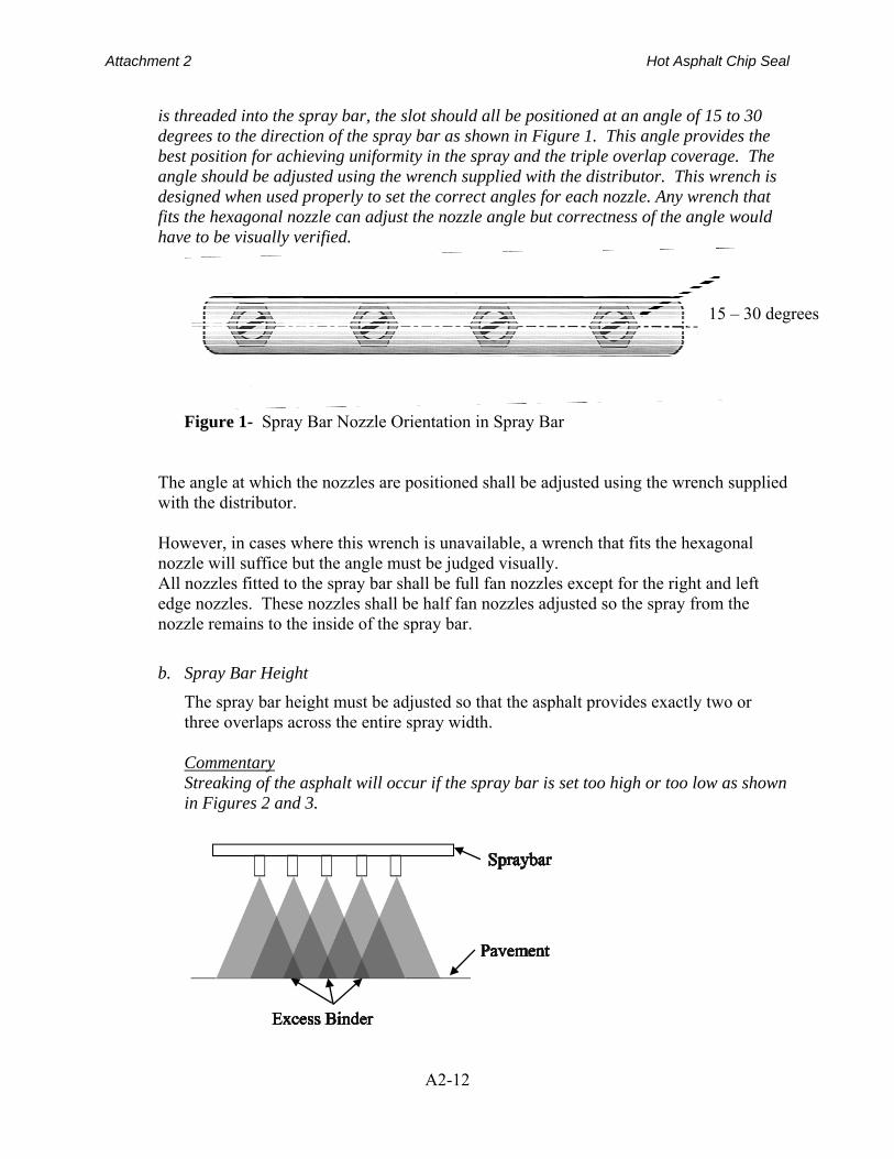
a. Nozzle Angle Nozzles shall be positioned at an angle of 15 to 30 degrees from the horizontal of the spray bar in accordance with the spray bar manufacturers recommendation. All nozzles shall spray a full fan except for the right and left edge nozzles. The right and left edge nozzle shall be adjusted to a half fan such that the spray stays to the inside of the spray bar. Commentary: The next step in calibrating the distributor is adjustment of the spray bar nozzle angles. Each nozzle has a slot cut across the face of the nozzle. When the nozzle
Attachment 2 Hot Asphalt Chip Seal
A2-12
is threaded into the spray bar, the slot should all be positioned at an angle of 15 to 30 degrees to the direction of the spray bar as shown in Figure 1. This angle provides the best position for achieving uniformity in the spray and the triple overlap coverage. The angle should be adjusted using the wrench supplied with the distributor. This wrench is designed when used properly to set the correct angles for each nozzle. Any wrench that fits the hexagonal nozzle can adjust the nozzle angle but correctness of the angle would have to be visually verified.
Figure 1- Spray Bar Nozzle Orientation in Spray Bar
The angle at which the nozzles are positioned shall be adjusted using the wrench supplied with the distributor. However, in cases where this wrench is unavailable, a wrench that fits the hexagonal nozzle will suffice but the angle must be judged visually. All nozzles fitted to the spray bar shall be full fan nozzles except for the right and left edge nozzles. These nozzles shall be half fan nozzles adjusted so the spray from the nozzle remains to the inside of the spray bar.
b. Spray Bar Height
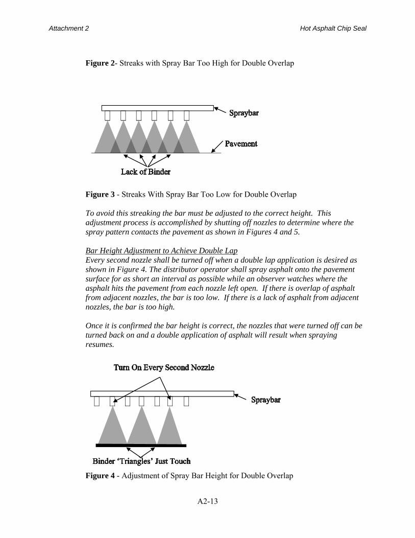
The spray bar height must be adjusted so that the asphalt provides exactly two or three overlaps across the entire spray width. Commentary Streaking of the asphalt will occur if the spray bar is set too high or too low as shown in Figures 2 and 3.
15 – 30 degrees
Attachment 2 Hot Asphalt Chip Seal
A2-13
Figure 2- Streaks with Spray Bar Too High for Double Overlap
Figure 3 - Streaks With Spray Bar Too Low for Double Overlap To avoid this streaking the bar must be adjusted to the correct height. This adjustment process is accomplished by shutting off nozzles to determine where the spray pattern contacts the pavement as shown in Figures 4 and 5. Bar Height Adjustment to Achieve Double Lap Every second nozzle shall be turned off when a double lap application is desired as shown in Figure 4. The distributor operator shall spray asphalt onto the pavement surface for as short an interval as possible while an observer watches where the asphalt hits the pavement from each nozzle left open. If there is overlap of asphalt from adjacent nozzles, the bar is too low. If there is a lack of asphalt from adjacent nozzles, the bar is too high. Once it is confirmed the bar height is correct, the nozzles that were turned off can be turned back on and a double application of asphalt will result when spraying resumes.
Figure 4 - Adjustment of Spray Bar Height for Double Overlap
Attachment 2 Hot Asphalt Chip Seal
A2-14
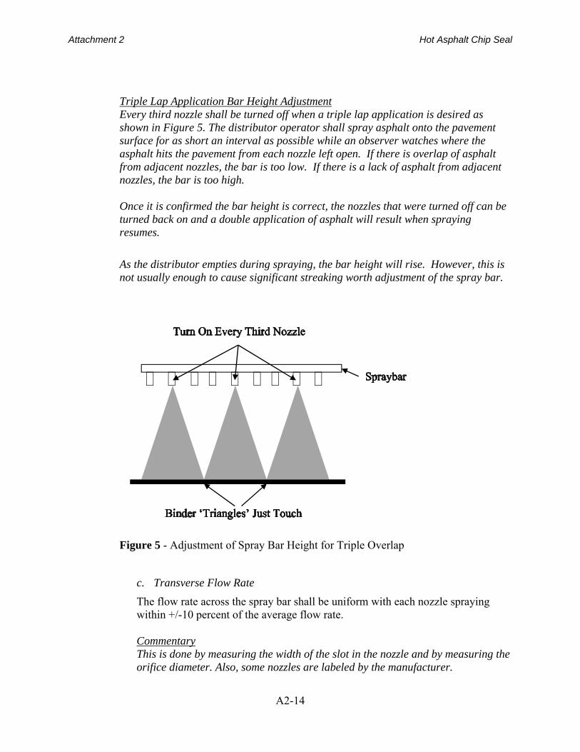
Triple Lap Application Bar Height Adjustment Every third nozzle shall be turned off when a triple lap application is desired as shown in Figure 5. The distributor operator shall spray asphalt onto the pavement surface for as short an interval as possible while an observer watches where the asphalt hits the pavement from each nozzle left open. If there is overlap of asphalt from adjacent nozzles, the bar is too low. If there is a lack of asphalt from adjacent nozzles, the bar is too high. Once it is confirmed the bar height is correct, the nozzles that were turned off can be turned back on and a double application of asphalt will result when spraying resumes.
As the distributor empties during spraying, the bar height will rise. However, this is not usually enough to cause significant streaking worth adjustment of the spray bar.
Figure 5 - Adjustment of Spray Bar Height for Triple Overlap
c. Transverse Flow Rate
The flow rate across the spray bar shall be uniform with each nozzle spraying within +/-10 percent of the average flow rate. Commentary This is done by measuring the width of the slot in the nozzle and by measuring the orifice diameter. Also, some nozzles are labeled by the manufacturer.
Attachment 2 Hot Asphalt Chip Seal
A2-15
Manufacturers supply a list of nozzles in the owner’s document describing which nozzles shall be used for various application rates or on a placard mounted on the equipment.
However, nozzles of the same apparent size have been measured with different flow rates. Therefore, it is recommended that all nozzles be checked for flow rate before chip seal operations begin. This is easily accomplished by fabricating a flow apparatus. This apparatus consists of a pipe to which each nozzle can be fitted, in turn, on one end and a water source can be fitted to the other end. The flow of water through each nozzle shall be measured by filling a one gallon container in a measured period. This shall be done for each nozzle to be used on the project. If the flow rate of any of the nozzles is greater than 10 percent of the average of all the nozzles to be used these nozzles shall be discarded, or modified to flow within the 10 percent tolerance. Determination of uniform lateral flow from the spray bar is determined by collecting a measured volume of asphalt in containers placed under each nozzle. This process is practical using standard 6-inch by 12-inch concrete cylinder molds lined with one-gallon zip-lock freezer bags. The cylinder molds can be reused and the zip lock bags discarded appropriately with the contents.
d. Longitudinal Flow Rate
The longitudinal spray rate shall be accomplished by measuring the volume of asphalt in the distributor before and after spraying enough asphalt to reduce the volume of asphalt in the distributor by 70 to 90 percent. Commentary The longitudinal flow rate must be measured with all nozzles inserted in the distributor bar. First, the quantity of emulsified asphalt in the truck must be determined. Although there is a volume indicator on the rear of most modern distributors, these are not calibrated in small enough increments to be of use for longitudinal flow rate calibration and shall not be used for this purpose. Instead, the dip stick supplied with the distributor must be used. This dip stick is usually carried on the top of the tank near the inspection hatch. Prior to shooting asphalt, take a volume reading with the dip stick. Pay attention to how the dipstick is used. Many dipsticks are not intended to be submerged in the asphalt, but instead, are inserted into the top of the tank only until the tip of the dipstick touches the surface of the asphalt. Then, the volume in the tank is read by indexing the top of the inspection cover to the reading on the dipstick.
Record this volume as ‘beginning volume’. Set up the truck to shoot asphalt and shoot a minimum of 3000 feet by 12 feet of asphalt at the design rate using the gallon per minute pump flow volume and truck speed required by the
Attachment 2 Hot Asphalt Chip Seal
A2-16
manufacturer to attain this flow rate. Take a second dip stick reading. Record this reading as ‘ending volume’. Subtract ‘ending volume’ from ‘beginning volume’ and record this as ‘volume used’. Determine the area of asphalt sprayed. Divide ‘volume used’ by the area sprayed in square yards. This is the gallons per square yard applied to the pavement. This value shall then be compared to the distributor computer, if equipped, to evaluate the accuracy of the computer. A correction factor may then be applied to the computer output, if needed, and used for the remainder of the day. This calibration shall be accomplished each day. An example of this calibration is presented below: Given: 1800-gallon capacity asphalt distributor 12-foot-wide spray width Trial spray distance = 3630 feet 0.32 gallon/yd2 design spray rate Dipstick reading beginning of shot = 1765 gallons Dipstick reading end of shot = 265 gallons Calculations:
4. Check to see if enough volume shot. 1765-265=1500 gallons 5. 1500/1765 = 85 percent >70% and <90%. OK, enough applied to be valid 6. Calculate spray rate = 1500 gallons / (12 x 3630/3) = 0.31 gallons/yd2
Therefore, decrease distributor speed, or recalibrate computer and re-check.
3. Aggregate Chip Spreader
a. Transverse Spread Rate
Commentary Various methods of calibrating this equipment have been used and the ASTM D5624 procedure can be effective. However, a visual assessment of the lateral distribution of chips is a good place to start the process since non-uniform distribution can easily be seen. The veil of chips deposited on the pavement from the spreader box can be viewed from behind with the spreader moving away from the observer or from the front. Either position for the observer is adequate for viewing how uniform the veil of chips is falling out of the spreader box. However, viewing from either front quarter affords the observer a better view of the entire spreader width and is, of course, safer than directly in front of the spreader. Any variation in light passing through the veil of chips indicates variation in application rate. More light means a lack of chips. Variation in light means the machine shall be stopped, the gates on the spreader contributing to the non-uniformity adjusted and the trial rerun. This procedure provides adjustment to
Attachment 2 Hot Asphalt Chip Seal
A2-17
the transverse spread rate. Then, to obtain an objective means of measuring the amount of chips being deposited, ASTM D5624, “Determining the Transverse Aggregate Spread Rate for Surface Treatment Applications” is a good procedure to use.
b. Longitudinal Spread Rate
Commentary Once the transverse spread rate is adjusted the longitudinal rate can be adjusted. This is also done visually, at first. Begin spreading chips into the fresh asphalt when a few chips cast by hand stick to the asphalt and do not roll over. This shall be done well before the asphalt begins to cool, but not immediately after spraying unless temperature and wind demand it. The application rate of the chips shall be similar to the design rate. This is a rate where immediately upon dropping the chips, the appearance of the surface has some asphalt showing between the chips. In fact, the chip quantity should seem somewhat inadequate. The chip spread rate should not be low enough to cause pickup problems on rubber-tire rollers. However, the rate should be such that a small decrease in rate would cause pickup. Asphalt should be visible between the chips upon dropping the chips and before rolling. If all asphalt is covered before rolling, there is an excess of chips and the rate shall be reduced. It is the responsibility of the construction superintendent to achieve this application rate. Evaluating the quantity of chips being placed is important after the rate is established. This provides a quantitative baseline for future work. The best method to accomplish this evaluation is by weighing the chip spreader before and after applying the chips and calculating the spread rate based on the area covered. This is often not practical. Therefore, a suitable alternative includes estimating the quantity of chips spread over a known area by knowing the weight of each transport truck supplying the spreader and dividing the estimated weight of chips spread by the area covered for that load. An example follows:
Given: Trucks loading the chip spreader are 12-ton capacity tandem dumps 12-foot-wide pavement 28 pounds per square yard design spread rate Calculations:
6. Check Truck No. 1 a. Load = 23,803 lbs. b. Spreader distance = 213 feet c. Rate = 23,803/213x12/3 = 27.9 lbs./yd2 7. Check Truck No. 2
Attachment 2 Hot Asphalt Chip Seal
A2-18
a. Load = 23,921 lbs. b. Spreader distance = 211 feet c. Rate = 23,921/211 x 12/3 = 28.3 lbs./yd2 8. Check Truck No. 3 a. Load = 23,848 lbs. b. Spreader distance = 213 feet c. Rate = 23,848/213 x 12/3 = 28.0 lbs./yd2 9. Average Rate = (27.9 + 28.3 + 28.0) / 3 = 28.1 lbs./yd2 10. No adjustment needed since measured rate is within 1 percent of design. Compensation for moisture on chips must be considered when calibrating chip spreaders. The above example indicates no adjustment is needed since the measured spread rate is within 0.10 lbs/yd2 of the design spread rate. However, if the chips above had contained as much as 1.02 percent moisture that was unaccounted for, the application rate would have been too low.
G. Test Strip
A test strip shall be constructed on or near the project site. Construct the test strip under similar placement conditions of time of day, temperature, and humidity as expected for the duration of the project. The test strip shall be a minimum of 300 feet in length and shall be constructed with the job mix proportions, materials, and equipment to be used on the project. Adjustments to the mixture formula shall be permitted provided they do not exceed the values stated in the mix design. The Agency shall evaluate the test strip to determine whether project specifications are met. If specifications are not met, additional test strips will be constructed until specifications are met, at no additional cost to the Agency.
H. Application of Asphalt Binder
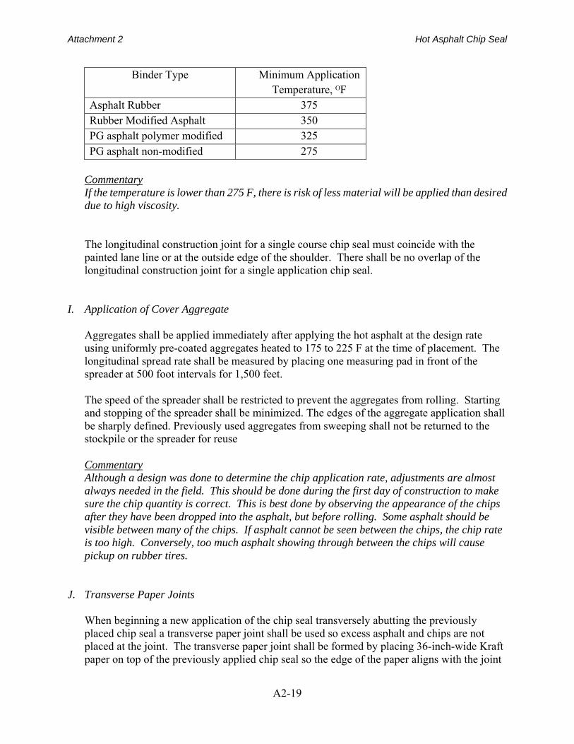
Apply the asphalt binder at the rate determined by the design. This rate shall be within +/- 5% of the chip seal design rate. After applying the binder, place the cover aggregate at the design application rate. Adjust the rate of application, if necessary, so that some binder can be seen between the aggregate chips, but not so much that aggregate chips adhere to the pneumatic rollers. Inspect the aggregate in the wheel paths for proper embedment. Embedment shall be 50 to 60 percent after rolling. Make additional adjustments to the rate of application during the project, if needed. The temperature of the binder asphalt at the time of application shall be as recommended by the contractor and approved by the Engineer. Recommendations for application temperatures are given in Table 4.
Table 4- Suggested Application Temperatures as a Function of Binder Type
Attachment 2 Hot Asphalt Chip Seal
A2-19
Binder Type Minimum Application Temperature, ᴼF
Asphalt Rubber 375 Rubber Modified Asphalt 350 PG asphalt polymer modified 325 PG asphalt non-modified 275
Commentary If the temperature is lower than 275 F, there is risk of less material will be applied than desired due to high viscosity.
The longitudinal construction joint for a single course chip seal must coincide with the painted lane line or at the outside edge of the shoulder. There shall be no overlap of the longitudinal construction joint for a single application chip seal.
I. Application of Cover Aggregate
Aggregates shall be applied immediately after applying the hot asphalt at the design rate using uniformly pre-coated aggregates heated to 175 to 225 F at the time of placement. The longitudinal spread rate shall be measured by placing one measuring pad in front of the spreader at 500 foot intervals for 1,500 feet. The speed of the spreader shall be restricted to prevent the aggregates from rolling. Starting and stopping of the spreader shall be minimized. The edges of the aggregate application shall be sharply defined. Previously used aggregates from sweeping shall not be returned to the stockpile or the spreader for reuse
Commentary Although a design was done to determine the chip application rate, adjustments are almost always needed in the field. This should be done during the first day of construction to make sure the chip quantity is correct. This is best done by observing the appearance of the chips after they have been dropped into the asphalt, but before rolling. Some asphalt should be visible between many of the chips. If asphalt cannot be seen between the chips, the chip rate is too high. Conversely, too much asphalt showing through between the chips will cause pickup on rubber tires.
J. Transverse Paper Joints
When beginning a new application of the chip seal transversely abutting the previously placed chip seal a transverse paper joint shall be used so excess asphalt and chips are not placed at the joint. The transverse paper joint shall be formed by placing 36-inch-wide Kraft paper on top of the previously applied chip seal so the edge of the paper aligns with the joint
Attachment 2 Hot Asphalt Chip Seal
A2-20
that will be formed when the previously placed chip seal meets the newly applied chip seal. The asphalt distributor shall begin applying asphalt binder by starting the application on top of the Kraft paper. After the distributor moves forward and over the joint the paper shall be removed. Commentary Ideally, the paper should also be placed at the end of the distributor shot, as well. This creates a clean, edge with the correct asphalt and chip quantity at the joint. Where the paper should be placed is calculated based on the asphalt shot rate and the quantity of asphalt in the distributor. The distance the distributor travels before encountering the paper and turning off the bar should be approximately equivalent to 80 percent of the distributor tank volume. This assures the distributor does not spray until empty which can result in less asphalt applied than desired at the end of the shot.
K. Rolling Operations Complete the first roller pass as soon as possible but not longer than two minutes after
applying the aggregate. Proceed in a longitudinal direction at a speed less than or equal to 5 to 7 miles per hour. Three complete roller passes of the aggregate chips are required. One pass is defined as the roller moving over the aggregates in a single direction. Ensure the rolling is completed quickly enough to embed the aggregate, before the binder cools and no longer than 15 minutes after the binder is applied. Position the rollers in echelon so the entire width of the pavement lane is covered in one pass of the rollers.
Commentary If desired, final rolling may be accomplished using the steel wheel roller in one pass
L. Sweeping
The removal of loose cover material shall commence after final rolling is completed such that the cover aggregate is not displaced and the asphalt surface is not damaged.
M. Traffic Control The treated roadway shall not be used by the contractor or its agents until it has been
established by the Engineer that the roadway will not be damaged or marred under the action of traffic. The contractor shall use signs or other traffic control devices to prevent traffic operating on the fresh chip seal. Any damage to the hot applied chip seal shall be repaired by the Contractor at no additional cost to the agency.
N. Protection of Motor Vehicles
Attachment 2 Hot Asphalt Chip Seal
A2-21
The Contractor shall be responsible for claims of damage to vehicles until the roadways and
shoulders have been swept free of loose aggregate and permanent markings have been applied. If permanent pavement markings are to be applied by Agency forces, the Contractor’s responsibility ends after completion of the chip seal.
O. Fog Seal
If, in accordance with the plans, a fog seal is applied to the surface of the completed chip seal, spray the fog seal after sweeping and before placement of permanent pavement markings, but not sooner than 24 hours after final rolling. Refer to the AASHTO Construction Guide Specification for Fog Seals in the section for application over chip seals for specific requirements. Commentary Fog seals are applied to the surface of completed chip seals for two reasons: 1) The dark color provides more contrast to pavement markings, 2) the fog seal provides a slight increase in binder residue to increase chip retention. A fog seal may also be applied to recent hot mix asphalt patches in the pavement to be chip sealed. These fresh hot mix patches can be more absorptive than the surrounding pavement due to higher air void content. The fog seal helps prevent the new chip seal asphalt from being absorbed into the substrate unevenly.
P. Sequence of Work Construct the chip seal so that adjacent lanes are sealed on the same day when possible.
If the adjacent lane(s) has not been sealed sweep all loose chips from the unsealed lane(s) before traffic is allowed on the surface without traffic control. The permanent pavement markings shall not be placed for three days after placing the fog seal for water borne pavement marking or ten days for other types of markings.
Commentary The chip seal will usually cure within 24 hours under dry conditions and temperatures above 60F. The fog seal can be applied after the chip seal coat is cured. The fog seal will usually cure within 2 hours under dry conditions and temperatures above 60F. Interim pavement markings can be placed after the fog seal cures.
Q. Quality Control
1. General The Contractor is responsible for quality control (QC) sampling and testing and shall submit a QC plan including materials and procedures for verifying the quality of the chip
Attachment 2 Hot Asphalt Chip Seal
A2-22
seal aggregates and emulsified asphalt(s). The Contractor’s QC plan shall include but is not limited to sampling, testing, inspection, monitoring, documentation, and corrective action procedures during transport, stockpiling and placement operations. A written Quality Control Plan (QCP) shall be developed which details the Contractors’ QC program that meets the requirements of these specifications. The QCP shall be contract specific and signed by the Contractors’ representative. Chip seal construction shall not proceed without Agency approval of the QCP and QC personnel present on the project. Failure to comply with these provisions will result in shutdown of the operations until such time as the Contractor’s operations are in compliance.
2. Personnel
The QC staff shall include the following as a minimum:
a. QCP Administrator – The person with overall responsibility of the QCP
b. QCP Manager – The person responsible for the execution of the QCP and liaison with the Agency. This person shall be on the project, and have the authority to stop or suspend construction operations.
c. QC Technicians – The person(s) responsible for conducting QC tests and inspection to implement the QCP. QC technicians shall have Level 2 Aggregate Testing Certification from the American Concrete Institute (ACI) or other accrediting body approved by the Agency.
d. Certified Crew Members – Three crew members (job foreman, aggregate spreader operator and asphalt distributor operator), at a minimum, shall possess a valid chip seal certification and be on the project at all times the chip seal is being constructed. The chip seal certification is administered by the National Center for Pavement Preservation (NCPP) on behalf of AASHTO TSP2 (Transportation Services Preservation Program).
3. Testing Facilities and Equipment
The Contractor shall provide the name of the laboratory conducting QC tests. The laboratory shall maintain accreditation by the AASHTO Accreditation Program (AAP) for all tests within the relevant scope of testing, or other accrediting body approved by the agency. Sampling, testing and measuring devices shall meet the requirements of the specified standards and test methods. The laboratory shall maintain records of the calibration and maintenance of all sampling, testing and measuring equipment.
4. Materials Testing
Chip seal aggregates and asphalt binders shall be tested for compliance with the specifications. Only asphalt binders from certified or approved sources shall be allowed.
Attachment 2 Hot Asphalt Chip Seal
A2-23
a. Asphalt Rubber
i. Sampling shall be completed at the point of manufacture. Testing and reporting shall be completed on these samples. As a minimum, the following data shall be reported for all samples:
ii. Total quantity of binder in tons
iii. Tons and percentage of ground tire rubber based on total asphalt rubber binder
iv. ASTM D-6114 certified test results
b. Rubberized asphalt.
i. Only asphalt binder from a certified or approved source is allowed for use.
ii. Verify the binder meets specifications by obtaining a certificate of compliance for each load provided
c. Performance Graded asphalts.
i. Only asphalt binder from a certified or approved source is allowed for use.
ii. Verify the binder meets specifications by obtaining a certificate of compliance for each load provided
d. Chip Seal Aggregate
i. Stockpile.
Test the aggregate gradation a minimum of once per day, or every 1500 tons, whichever is less in accordance with AASHTO T27 to determine compliance with Table 4 requirements. If the material is hauled from the production site to a temporary stockpile, test at the temporary stockpile.
ii. Construction.
Test the aggregate gradation from the hopper of the chip spreader a minimum of once per day, or every 1500 tons, whichever is less in accordance with AASHTO T27 to determine compliance with Table 4 requirements. The testing rate for quality values in Table 5 shall be once per source.
e. Emulsified asphalt for fog seal Only emulsified asphalt from certified or approved sources is allowed for use.
Verify the asphalt(s) meet the specifications by obtaining certificates of compliance from the supplier.
Verify the application rate of the emulsified asphalt by dividing the volume of
emulsified asphalt used by the area chip sealed each day. Allowable variation is +/- 5% of the application rate adjusted from the design quantity. Provide material certification and quality control test results for each batch of emulsified asphalt used

Attachment 2 Hot Asphalt Chip Seal
A2-24
on the project. Include the supplier name, plant location, asphalt grade, and batch number on all reports.
5. Calibration of Equipment and Workmanship
Describe the equipment and methods used to calibrate the chip spreader and asphalt distributor including:
a. Longitudinal application rates b. Transverse application rates
Describe the process to be used to ensure
a. Good workmanship including; asphalt transverse application uniformity b. Transverse joint construction technique c. Longitudinal and transverse joints construction techniques d. Monitoring methods for application rates to minimize bleeding, rock loss and
streaking e. Rolling operations detailing rolling pattern and number of passes or coverages f. Sweeping operations and schedule g. Method of controlling traffic
6. Documentation
Describe the documentation and reporting procedures for all QC activities. Include samples of all QC test forms, inspection and test reports.
7. Records and Documentation
The Contractor shall maintain complete records of all QC tests and inspections. All QC test results shall be submitted to the Agency at the end of the contract. A material certification shall be submitted from each supplier for each batch of material delivered to the project, including test results. The QC records shall contain all test and inspection reports, forms and checklists, equipment calibrations, supplier material certificates, and non-conformance and corrective action reports. The QC records shall indicate the nature and number of observations made, the number and type of deficiencies found, the quantities conforming and non-conforming, and the nature of corrective action taken as appropriate for materials as well as workmanship. The QC records shall be available to the Agency at all times, and shall be retained by the contractor for the life of the contract. The Contractor’s documentation procedures will be subject to approval by the Agency prior to the start of work, and to compliance checks by the Agency during the progress of the work.
8. Compliance with Specifications
Attachment 2 Hot Asphalt Chip Seal
A2-25
The Contractor shall attest in writing to the Agency that the chip seal has been constructed in accordance with and meets the requirements of the specifications at the conclusion of the project.
R. Agency Acceptance
1. General The Agency will conduct acceptance sampling, testing, and inspection activities to ensure material quality, correct application rates, rolling, sweeping, and traffic control are within specification requirements. These activities will be done randomly by the Agency.
2. Acceptance Activities
a. Materials Testing
i. Asphalt Binders.
Sample the first shipment and provide one sample for every 50,000 gallons (approximately 200 tons) thereafter. Testing of the binders shall be in accordance with AASHTO M320 or 322.
ii. Aggregate
Sample aggregate taken from the chip spreader hopper once per day. Samples shall be stored and tested for gradation at the discretion of the Agency. If the results vary from the requirements of Tables 2 and 3, a price reduction shall be applied per the Schedule of Price Reduction prepared by the owner agency. Price adjustments are not included in this guide since most agencies do not use them for this type of treatment.
iii. Fog Seal Emulsion
Sample the first shipment and provide one sample for every 50,000 gallons (approximately 200 tons) thereafter. Testing of emulsions shall be in accordance with AASHTO M140, M208, and M316.
b. Equipment
All equipment to be used on the project shall be evaluated by the Agency to assure it is in acceptable operating condition, calibrated correctly and shall provide the quantities of material specified.
c. Final Inspection
Attachment 2 Hot Asphalt Chip Seal
A2-26
A final inspection shall be done to assure that no bleeding or flushing, excessive chip loss or crushed aggregate has occurred. Longitudinal and transverse joints shall be inspected to assure that no excessive overlap has occurred.
407.04 MEASUREMENT
The Engineer shall measure work acceptably completed as specified in Subsection 109.01 of the AASHTO Construction Guide Specifications and as follows:
A. When Payment is by Unit Price
1. Asphalt Binders Measure the asphalt binder used for the for chip seal by volume, at 60F.
2. Aggregate Chips
Aggregate chips will be measured by the area of pavement surfaced.
Commentary Chips can be paid for by the ton, as well. This is easier to verify, but results in an incentive to place more chips than necessary. Applying too many chips is poor practice and results in dislodgement of embedded chips. Also, paying by the ton will result in unnecessary additional cost.
407.05 PAYMENT
Payment for chip seals can be done by either paying for the materials in unit costs, or for the completed chip seal by area of pavement sealed.
Commentary
The advantage of payment by the square yard for a completed chip seal is simplicity if the area is easily defined. The disadvantage is that an incentive is created to reduce material quantities. Reduced asphalt quantities can lead to chip loss and vehicle damage.
A. Payment by Unit Price
The Agency shall pay for accepted quantities at the contract price as follows:
Attachment 2 Hot Asphalt Chip Seal
A2-27
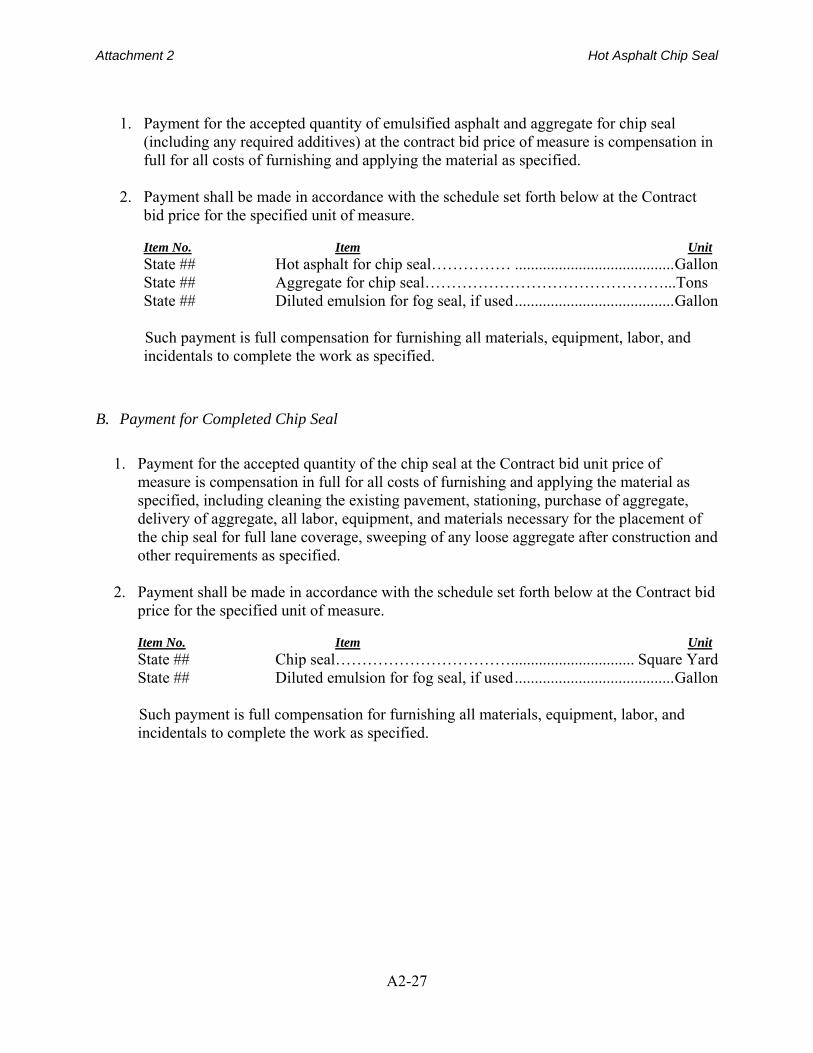
1. Payment for the accepted quantity of emulsified asphalt and aggregate for chip seal
(including any required additives) at the contract bid price of measure is compensation in full for all costs of furnishing and applying the material as specified.
2. Payment shall be made in accordance with the schedule set forth below at the Contract bid price for the specified unit of measure.
Item No. Item Unit State ## Hot asphalt for chip seal…………… ........................................ Gallon State ## Aggregate for chip seal………………………………………...Tons State ## Diluted emulsion for fog seal, if used ........................................ Gallon
Such payment is full compensation for furnishing all materials, equipment, labor, and incidentals to complete the work as specified.
B. Payment for Completed Chip Seal
1. Payment for the accepted quantity of the chip seal at the Contract bid unit price of
measure is compensation in full for all costs of furnishing and applying the material as specified, including cleaning the existing pavement, stationing, purchase of aggregate, delivery of aggregate, all labor, equipment, and materials necessary for the placement of the chip seal for full lane coverage, sweeping of any loose aggregate after construction and other requirements as specified.
2. Payment shall be made in accordance with the schedule set forth below at the Contract bid
price for the specified unit of measure.
Item No. Item Unit State ## Chip seal……………………………............................... Square Yard State ## Diluted emulsion for fog seal, if used ........................................ Gallon
Such payment is full compensation for furnishing all materials, equipment, labor, and incidentals to complete the work as specified.