ATM SOFTWARE
125
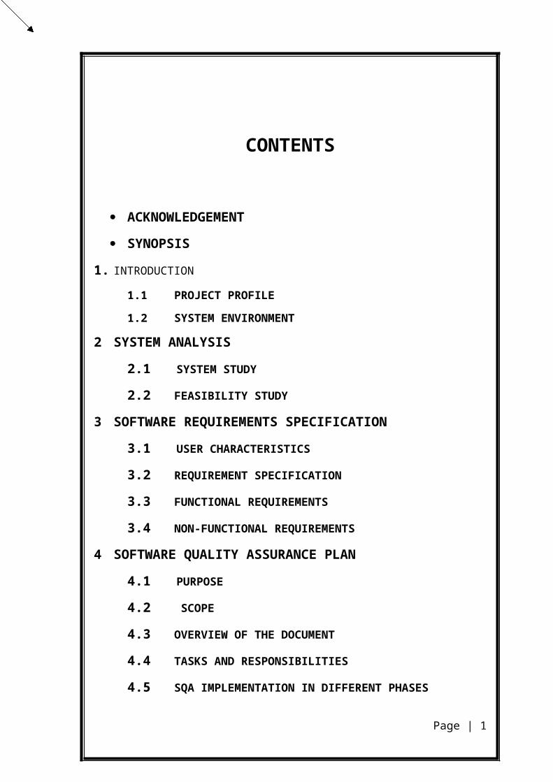
CONTENTS ACKNOWLEDGEMENT SYNOPSIS 1. INTRODUCTION 1.1 PROJECT PROFILE 1.2 SYSTEM ENVIRONMENT 2 SYSTEM ANALYSIS 2.1 SYSTEM STUDY 2.2 FEASIBILITY STUDY 3 SOFTWARE REQUIREMENTS SPECIFICATION 3.1 USER CHARACTERISTICS 3.2 REQUIREMENT SPECIFICATION 3.3 FUNCTIONAL REQUIREMENTS 3.4 NON-FUNCTIONAL REQUIREMENTS 4 SOFTWARE QUALITY ASSURANCE PLAN 4.1 PURPOSE 4.2 SCOPE 4.3 OVERVIEW OF THE DOCUMENT 4.4 TASKS AND RESPONSIBILITIES 4.5 SQA IMPLEMENTATION IN DIFFERENT PHASES Page | 1
-
Upload
hemant-kumar -
Category
Documents
-
view
110 -
download
1
Transcript of ATM SOFTWARE
CONTENTS
ACKNOWLEDGEMENT
SYNOPSIS
1. INTRODUCTION
1.1 PROJECT PROFILE
1.2 SYSTEM ENVIRONMENT
2 SYSTEM ANALYSIS
2.1 SYSTEM STUDY
2.2 FEASIBILITY STUDY
3 SOFTWARE REQUIREMENTS SPECIFICATION
3.1 USER CHARACTERISTICS
3.2 REQUIREMENT SPECIFICATION
3.3 FUNCTIONAL REQUIREMENTS
3.4 NON-FUNCTIONAL REQUIREMENTS
4 SOFTWARE QUALITY ASSURANCE PLAN
4.1 PURPOSE
4.2 SCOPE
4.3 OVERVIEW OF THE DOCUMENT
4.4 TASKS AND RESPONSIBILITIES
4.5 SQA IMPLEMENTATION IN DIFFERENT PHASES
4.6 DOCUMENTATION
4.7 SOFTWARE DOCUMENTATION AUDIT
4.8 REQUIREMENTS TRACEABILITY
4.9 SOFTWARE DEVELOPMENT PROCESS
4.10 PROJECT REVIEW
Page | 1
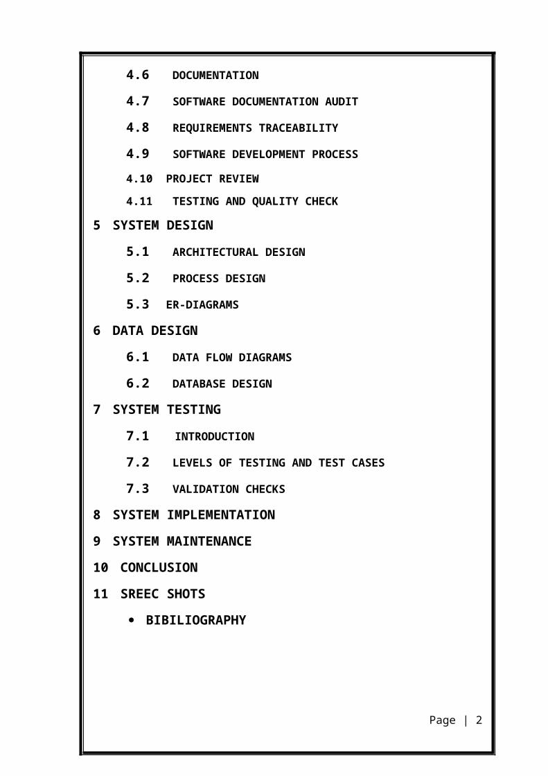
4.11 TESTING AND QUALITY CHECK
5 SYSTEM DESIGN
5.1 ARCHITECTURAL DESIGN
5.2 PROCESS DESIGN
5.3 ER-DIAGRAMS
6 DATA DESIGN
6.1 DATA FLOW DIAGRAMS
6.2 DATABASE DESIGN
7 SYSTEM TESTING
7.1 INTRODUCTION
7.2 LEVELS OF TESTING AND TEST CASES
7.3 VALIDATION CHECKS
8 SYSTEM IMPLEMENTATION
9 SYSTEM MAINTENANCE
10 CONCLUSION
11 SREEC SHOTS
BIBILIOGRAPHY
Page | 2
ACKNOWLEDGEMENT
Completing a task is never a one-man effort. It offers the result of valuable
contribution of a number of individuals in a direct or indirect manner that helps in shaping
and achieving an objective.
This project would not have taken shape, but for the
guidance provided by Mrs. Malathi, faculty member of DCA CUSAT and . Mr. A.
Sreekumar faculty member of DCA CUSAT has helped me so much.
I express my profound gratitude to Dr.K.V.Pramod, Head of the Department
and all staff members of the Department of Computer Applications for their endless help
and support.
The guidance and support received from all the members who contributed and
who are contributing to this project, was vital for the success of the project. I am grateful
for their constant support and help.
I wish to express my heartfelt gratitude to my family, who has always been the
singular source of inspiration in all my ventures I have undertaken. Also I thank all my
friends for their help and suggestions.
Above all I thank the Almighty for His blessings and providing mercies at all
stages of my work.
HEMANT KUMAR
Page | 3
SYNOPSIS
‘ATM Software’ is to develop a real time, customizable software for
ATM MACHINE of which is easily portable, adaptable and customizable to
multiple hardware and software.
This include provision for adding Operator account, Withdrawing
money, Depositing money, Transferring money from one account to another
account, Changing PIN. No, View Balance and Mini Statement about your
transaction.
This facility obviates the difficulties of loss, fraud, and delay in
transfer, etc. and offers scope for paperless effort.
Page | 4
INTRODUCTION
1.1 PROJECT PROFILE
‘ATM Software’ is to develop a real time Software for
Automatic Teller Machine
The software to be designed will control a simulated automated teller machine (ATM) . The ATM will communicate with the bank's computer over an appropriate communication link.
The ATM will service one customer at a time. A customer will be required to insert an ATM card and enter a personal identification number (PIN) - both of which will be sent to the bank for validation as part of each transaction. The customer will then be able to perform one or more transactions. The card will be retained in the machine until the customer indicates that he/she desires no further transactions, at which point it will be returned - except as noted below.
A customer must be able to make a deposit to any account linked to the card, consisting of cash and/or checks in an envelope. The customer will enter the amount of the deposit into the ATM, subject to manual verification when the envelope is removed from the machine by an operator. Approval must be obtained from the bank before physically accepting the envelope.
A customer must be able to make a transfer of money between any two accounts linked to the card.
A customer must be able to make a balance inquiry of any account linked to the card.
A customer must be able to abort a transaction in progress by pressing the Cancel key instead of responding to a request from the machine.
The ATM will communicate each transaction to the bank and obtain verification that it was allowed by the bank. Ordinarily, a transaction will be considered complete by the bank once it has been approved. In the case of a deposit, a second message will be sent to the bank indicating that the customer has deposited the envelope.
If the bank determines that the customer's PIN is invalid, the customer will be required to re-enter the PIN before a transaction can proceed. If the customer is unable to
Page | 5
successfully enter the PIN after three tries, the card will be permanently retained by the machine, and the customer will have to contact the bank to get it back.
If a transaction fails for any reason other than an invalid PIN, the ATM will display an explanation of the problem, and will then ask the customer whether he/she wants to do another transaction.
The ATM will provide the customer with a printed receipt for each successful transaction, showing the date, time, type of transaction, account(s), amount, and ending and available balance(s) of the affected account ("to" account for transfers).
The ATM will have a key-operated switch that will allow an operator to start and stop the servicing of customers. The machine can only be turned off by operator. When the switch is moved to the "off" position, the machine will shut down.. The ATM will also maintain an internal log of transactions to facilitate resolving ambiguities arising from a hardware failure in the middle of a transaction. Entries will be made in the log when the ATM is started up and shut down, for each message sent to the Bank (along with the response back, if one is expected), for the dispensing of cash, and for the receiving of cash. Log entries may contain card numbers and Customer identification number.
The major objective of the proposal is to There are many issues when automating a process, such as the developed software should have a simple and user friendly interface that will free the user from the complexities of the software. The Administrator has the rights to input & change the receipt details.
All risks associated with physical certificates such as delays, loss, theft, bad deliveries, etc. eliminated. And also calculation delay is reduced. So the overall objective of the system is to develop user-friendly, secure, consistent and flexible software so that the effort required to prepare the cashbook can be reduced.
Page | 6
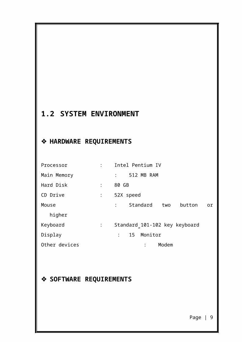
1.2 SYSTEM ENVIRONMENT
HARDWARE REQUIREMENTS
Processor : Intel Pentium IV
Main Memory : 512 MB RAM
Hard Disk : 80 GB
CD Drive : 52X speed
Mouse : Standard two button or higher
Keyboard : Standard 101-102 key keyboard
Display : 15” Monitor
Other devices : Modem
SOFTWARE REQUIREMENTS
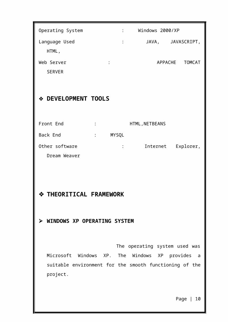
Operating System : Windows 2000/XP
Language Used : JAVA, JAVASCRIPT, HTML,
Web Server : APPACHE TOMCAT SERVER
DEVELOPMENT TOOLS
Front End : HTML,NETBEANS
Back End : MYSQL
Page | 7
Other software : Internet Explorer, Dream Weaver
THEORITICAL FRAMEWORK
WINDOWS XP OPERATING SYSTEM
The operating system used was Microsoft Windows XP. The
Windows XP provides a suitable environment for the smooth functioning of the
project.
Windows XP makes personal computing easy. Power, performance,
a bright new look and plenty of help when you need it. Windows XP has it all,
along with unmatched dependability and security.
Windows XP professional marks a new standard in business
software combining enterprise-class performance and reliability with
unprecedented ease of use. Built on the rock-solid foundation of Microsoft’s
proven Windows 2000 technology, Windows XP Professional contains all the
features of Microsoft Windows XP Home Edition, and includes new and enhanced
features designed especially for business and advanced use.
The all-new Help and Support Center in Windows XP is our one-stop shop for:
Clear how-to instructions
Engaging start-to-finish articles
Troubleshooting advice.
Special wizards give you step-by-step instructions to smooth the
way when connecting new devices and running new software.
Page | 8
HISTORY OF JAVA
Java is a programming language originally developed by James Gosling at Sun Microsystems and released in 1995 as a core component of Sun Microsystems' Java platform. The language derives much of its syntax from C and C++ but has a simpler object model and fewer low-level facilities. Java applications are typically compiled to bytecode (class file) that can run on any Java virtual machine (JVM) regardless of computer architecture.
The original and reference implementation Java compilers, virtual machines, and class libraries were developed by Sun from 1995. As of May 2007, in compliance with the specifications of the Java Community Process, Sun made available most of their Java technologies as free software under the GNU General Public License. Others have also developed alternative implementations of these Sun technologies, such as the GNU Compiler for Java and GNU Class path.
Overview of JavaJava is loosely based on C++ syntax, and is meant to be Object-
Oriented Structure of java is midway between an interpreted and a
compiled language. The java compiler into Byte Codes, which are
secure and portable across different platforms, compiles Java
programs. These byte codes are essentially instructions
encapsulated in single type, to what is known as a java virtual
machine (JVM), which resides in standard browser.
JVM verifies these byte codes when downloaded by the browser for integrity. JVM available for almost all OS. JVM converts these byte codes into machine specific instructions at runtime.
FEATURES OF JAVA
Java is object-oriented language and supports encapsulation,
inheritance, polymorphism and dynamic binding, but does not
support multiple inheritances. Everything in java is an object
except some primitive data types.
Page | 9
Java is portable architecture neutral that is java programs
once compiled can be executed on any machine that is
enabled.
Java is distributed in its approach and used for Internet
programming.
Java is robust, secured, high performing and dynamic in
nature.
Java supports multithreading. There for different parts of the
program can be executed at the same time.
About JSP
Overview of JSPThe JSP technology will be used to interface HTML with Java. The
JSP technology provides a seamless connection with Java and
presents an easy to use, Java-like programming constructs that can
be scripted within HTML files. Java Server Pages is a technology for
developing web pages that include dynamic content. A JSP page
contains standard markup language elements, such as HTML tags,
just like a regular web page. A JSP page also contains special JSP
elements that allow the server to insert dynamic content in the web
page.
ADVANTAGES OF JSP
JSP supports both scripting and element-based dynamic content.
Allows developing custom tag libraries.
JSP pages are precompiled for efficient server processing.
JSP pages can be used in combination with servlets that handle the business logic.
High Security.
Page | 10
Can run on any J2EE compatible web Server.
It can run on any OS that have J2EE compatible web server.
JSP separates the dynamic and static parts.
High Quality tool supports.
JSP supports N tier Application.
Write Once, Run Everywhere.
JSP is vender Neutral.
JAVA SCRIPT & HTML
JavaScript is an object based scripting language that offers cross
platform operation across the span of the WWW. JavaScript provides a means of
embedding interactive paths and intelligence within HTML documents. The object-
based nature of JavaScript offers programmers significant power and flexibility
through the ability to create functions and new objects. Performing certain
processing functions at the client side – such as form validation and data retrieval
from local data arrays-reduces the burden imposed on the server side and can
provide a sense of greater responsiveness to a viewer an HTML document
enhanced with JavaScript.
As the term website development sounds unique language strikes
is every one’s mind, which is nothing but hypertext Markup Language. This
language specifies all the function in a single sentence, which is called as Tag. This
language has Built-in Tags to specify the contents of the Web Pages. The main
advantage of this language is easy to learn and use. It does not state out the errors.
Browser based software takes less memory and executes at faster rate. All browser
based software executes at client side and hence in faster execution.
JavaScript is a scripting language most often used for client-side
web development. Its standardized name is ECMA Script, though “JavaScript” is
much more commonly used. “JavaScript” is actually Netscape Communications
Page | 11
Corporation’s (and now the Mozilla Foundation’s) implementation of the ECMA
Script standard. JavaScript is a dynamic, weakly typed, prototype-based language
with first class functions. JavaScript was influenced by many languages and was
designed to have a similar look to Java, but be easier for non-programmers to work
with. The language is best known for its use in websites (as client-side JavaScript),
but is also used to enable scripting access to objects embedded in other
applications. Despite the name, JavaScript is unrelated to the Java programming
language; though both
Have a common debt to C syntax. The language was renamed
from Live Script in a co-marketing deal between Netscape and Sun in exchange for
Netscape bundling Sun’s Java runtime with their browser, which was dominant at
the time. JavaScript semantics is much more similar to the self-programming
language. “JavaScript” is a registered trademark of Sun Microsystems Inc.
HTML, short for Hypertext Markup Language, is the
predominant markup language for the creation of web pages. It provides a means to
describe the structure of text-based information in a document — by denoting
certain text as headings, paragraphs, lists, and so on — and to supplement that text
with interactive forms, embedded images, and other objects. HTML is written in
the form of labels (known as tags), surrounded by less-than (<) and greater-than
signs (>). HTML can also describe, to some degree, the appearance and semantics
of a document, and can include embedded scripting language code which can
affect the behavior of web browsers and other HTML processors.
HTML was originally developed by Tim Berners-Lee while at
CERN, and popularized by the Mosaic browser developed at NCSA. During the
course of the 1990s it has blossomed with the explosive growth of the Web. During
this time, HTML has been extended in a number of ways. The Web depends on
Web page authors and vendors sharing the same conventions for HTML. This has
motivated joint work on specifications for HTML.
Website is a collection of pages, publications and documents
that receive on web server. While these bags publications and a document as a
Page | 12
formatted in any single format. You should use HTML for home page and all
primary pages and the site.
An HTML code is essentially a set of instructions given to a
web browser for formatting and layout of web page. HTML does not actually tell a
computer how the web page will look to a visitor rather that you use HTML to
compose the page to specify all the elements that appear on the page-the text,
graphics, horizontal rule, heading division and so on. In addition we use HTML to
tell a computer what color to use where and to indicate the relative size and font of
text.
.
OTHER SOFTWARES
DREAMWEAVER
Dreamweaver is used because it provides a high quality design with ease of designing.
BROWSERS
A Browser is a software program used to view HTML
documents within the World Wide Web. The primary goal of a web browser is to
send and receive data from the Web Server that provides the Web page. The server
sends the web page in the HTML markup language and the browser interprets that
HTML code, presenting the page to the user.
INTERNET EXPLORER
Internet is the Microsoft‘s contribution to the Web browser
community. The Internet Explorer is based on Microsoft’s ActiveX technology and
is available for Windows, Windows NT, and Macintosh platforms. One significant
capability of the Internet Explorer is that support the embedded intrinsic and
ActiveX controls within the Web pages, with which JavaScript can interact.
About Apache Tomcat
Page | 13
Overview of Apache Tomcat Apache Tomcat is a servlet container developed by the Apache Software Foundation (ASF). Tomcat implements the Java Servlet and the JavaServer Pages (JSP) specifications from Sun Microsystems, and provides a "pure Java" HTTP web server environment for Java code to run.Tomcat should not be confused with the Apache web server, which is a C implementation of an HTTP web server; these two web servers are not bundled together. Apache Tomcat includes tools for configuration and management, but can also be configured by editing XML configuration files.ComponentsTomcat version 4.x was released with Jasper (a redesigned JSP engine), Catalina (a redesigned servlet container) and Coyote (an HTTP connector).CatalinaCatalina is Tomcat's servlet container. Catalina implements Sun Microsystems' specifications for servlet and JavaServer Pages (JSP). The architect for Catalina was Craig McClanahan.
ABOUT THE TOOL
MYSQL
The back end of the application is provided by MySql.
The MySql database is the world’s most popular open source
database. Its architecture makes it extremely fast and easy to customize. Extensive
reuse of code within the software and a minimalist approach to producing
functionality-rich features has resulted in a database management system
unmatched in speed, compactness, stability and ease of deployment. The unique
separation of the core server from the storage engine makes it possible to run with
strict transaction control or with ultra-fast transaction less disk access, whichever is
most appropriate for the situation.
MySql is Open Source software. Open Source means that it is
possible for anyone to use and modify. Anybody can download MySql from the
internet and use it without paying anything. Anybody so inclined can study the
source code and change it to their needs.
MySQL is a multithreaded, SQL database management system
(DBMS), which allows threads to be allocated between processes to achieve a
Page | 14
higher degree of parallelism. MYSQL is based on a tiered architecture, consisting
of both primary subsystems and support components that interact with each other
to read, parse and execute queries, and to cache and return query results.
Primary subsystems
The Query Engine
The Storage Manager
The Buffer Manager
The Transaction Manager
The Recovery Manager
In addition to five primary subsystems, the MySql architecture
contains the following two support components.
The Process Manager
Function Libraries
MySql supports small, embedded kiosk-style applications as
well as the occasional five billion-record data warehouse. This versatility is
possible in part because of the MySql engine, which has been designed for
maximum scalability, maximum resource efficiency, and easy portability to
various platforms and architectures. MySql is designed on the assumption that the
vast majority of its applications will be running on TCP/IP (Transmission Control
Protocol/Internet Protocol) network.
MySql supports engine-level data integrity through the use of
primary key and foreign key constraints. Columns can be defined so that explicit
NULL values cannot be entered into them. To prevent empty columns, MySql
supports the use of default values, which, when combined with NOT NULL
properties, ensure that valid data is entered into a column that would otherwise be
left blank.
Security
The process of accessing a MySql database can be broken down
into two tasks: connecting to the MySql server itself, and accessing individual
Page | 15
objects, such as tables or columns, in a database. MySql has built-in security to
verify user credentials at both stages.
WAMP SERVER
WAMP is a form of mini-server that can run on almost any
Windows Operating System. WAMP includes Apache 2, PHP 5 (SMTP ports are
disabled), and MySQL (phpMyAdmin and SQLitemanager are installed to manage
your databases) preinstalled.
An icon on the taskbar tray displays the status of WAMP, letting you know if;
WAMP is running but no services are opened (the icon will appear red).
WAMP is running and one service is opened (the icon will appear
yellow).
WAMP is running with all services opened (the icon will appear white).
Apache and MySQL are considered to be services (they can be
disabled by left-clicking on the taskbar icon, guiding your cursor over the service
you wish to disable and selecting "Stop Service").
The files/web pages that are hosted on your WAMP server can
be accessed by typing http://localhost/ or http://127.0.0.1/ in the address bar of
your web browser. WAMP must be running in order to access either of the above
addresses.
Page | 16
SYSTEM ANALYSIS2. SYSTEM ANALYSIS
System analysis is the process of gathering and interpreting facts,
diagnosing problems and using the facts to improve the system. System specifies
what system should do. A system is a set of components that interact to accomplish
some purpose.
Identifying the drawback of the existing system
Identify the need for conversion
Perform feasibility study
Identify hardware, software and database requirements
Create a system definition that forms the foundation for subsequent
work
2.1 SYSTEM STUDY
PROBLEM STATEMENT
Develop secure, consistent and flexible software which can used for
Customer transaction
PROPOSED SYSTEM
Page | 17
The Proposed system should satisfy all the features of the existing
system, barring the some disadvantages . The Proposed system
Allows faster workflow since everything is automated.
Each Card number has a unique number which helps the transactions to
be more secure.
The administrator have update limited authority
BENEFITS OF THE PROJECT
It minimize time and work.
Give the better security by using SHA/MD5 for digesting ,RSA algorithm for
security on network and SAMIR ZERO KNOWELDGE PROTOCOL for
security of PIN NO.
It provides Transactional secrecy and integrity, customer identity integrity And customer security.
.
2.2 FEASIBILITY STUDY
The feasibility of a project can be ascertained in terms of technical factors, economic factors, or both. A feasibility study is documented with a report showing all the ramifications of the project
Technical Feasibility. Technical feasibility refers to the ability of the process to take advantage of the current state of the technology in pursuing further improvement. The technical capability of the personnel as well as the capability of the available technology should be considered. Technology transfer between geographical areas and cultures needs to be analyzed to understand productivity loss (or gain) due to differences (see Cultural Feasibility). Since we are using Java 6, Tomcat 5.5 and so on so technically our project is feasible.
Economic Feasibility. This involves the feasibility of the proposed project to generate economic benefits. A benefit-cost analysis and a breakeven analysis are important aspects of evaluating the economic feasibility of new industrial projects. The tangible and intangible aspects of a project should be translated into economic terms to facilitate a consistent basis for evaluation.
Page | 18
Financial Feasibility. Financial feasibility should be distinguished from economic feasibility. Financial feasibility involves the capability of the project organization to raise the appropriate funds needed to implement the proposed project. Project financing can be a major obstacle in large multi-party projects because of the level of capital required. Loan availability, credit worthiness, equity, and loan schedule are important aspects of financial feasibility analysis.
Cultural Feasibility. Cultural feasibility deals with the compatibility of the proposed project with the cultural setup of the project environment. In labor-intensive projects, planned functions must be integrated with the local cultural practices and beliefs. For example, religious beliefs may influence what an individual is willing to do or not do.
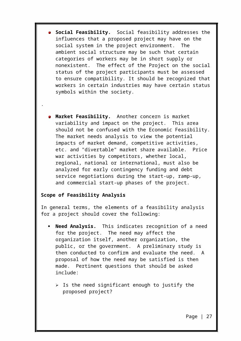
Social Feasibility. Social feasibility addresses the influences that a proposed project may have on the social system in the project environment. The ambient social structure may be such that certain categories of workers may be in short supply or nonexistent. The effect of the Project on the social status of the project participants must be assessed to ensure compatibility. It should be recognized that workers in certain industries may have certain status symbols within the society.
.
Market Feasibility. Another concern is market variability and impact on the project. This area should not be confused with the Economic Feasibility. The market needs analysis to view the potential impacts of market demand, competitive activities, etc. and "divertable" market share available. Price war activities by competitors, whether local, regional, national or international, must also be analyzed for early contingency funding and debt service negotiations during the start-up, ramp-up, and commercial start-up phases of the project.
Scope of Feasibility Analysis
In general terms, the elements of a feasibility analysis for a project should cover the following:
Need Analysis. This indicates recognition of a need for the project. The need may affect the organization itself, another organization, the public, or the government. A preliminary study is then conducted to confirm and evaluate the need. A proposal of how the need may be satisfied is then made. Pertinent questions that should be asked include:
Is the need significant enough to justify the proposed project? Will the need still exist by the time the project is completed? What are the alternate means of satisfying the need? What are the economic, social, environmental, and political impacts of the
need?
Page | 19
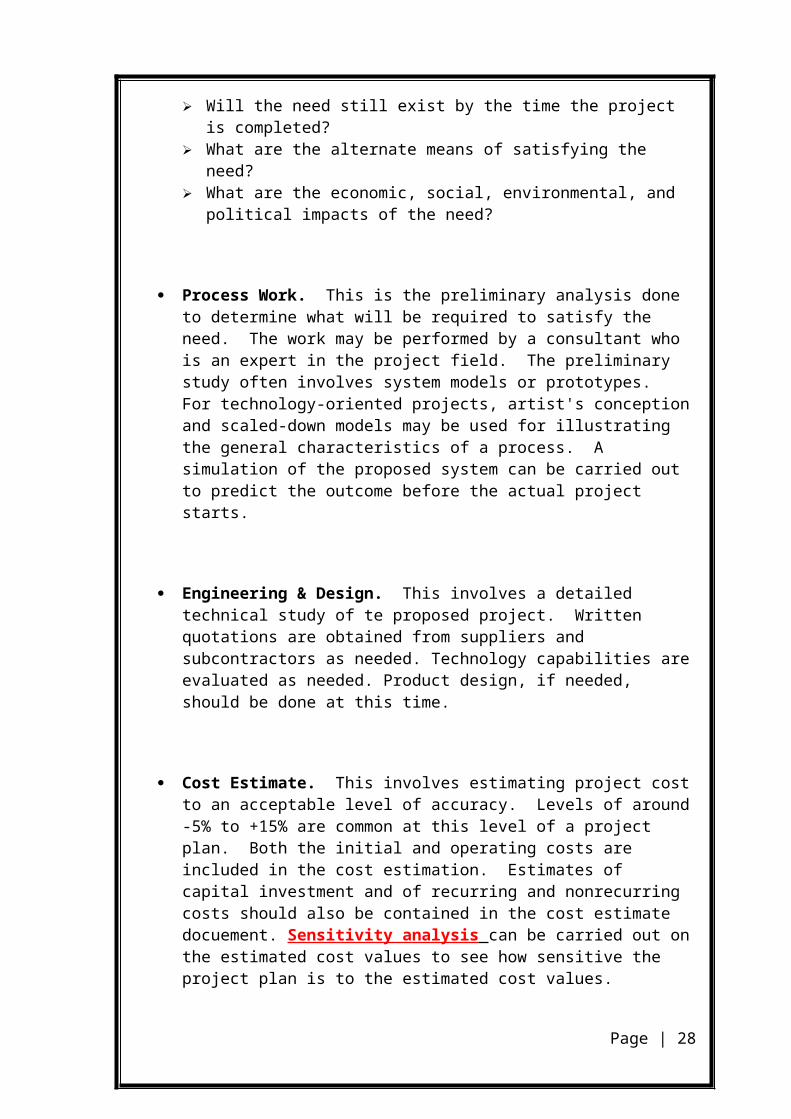
Process Work. This is the preliminary analysis done to determine what will be required to satisfy the need. The work may be performed by a consultant who is an expert in the project field. The preliminary study often involves system models or prototypes. For technology-oriented projects, artist's conception and scaled-down models may be used for illustrating the general characteristics of a process. A simulation of the proposed system can be carried out to predict the outcome before the actual project starts.
Engineering & Design. This involves a detailed technical study of te proposed project. Written quotations are obtained from suppliers and subcontractors as needed. Technology capabilities are evaluated as needed. Product design, if needed, should be done at this time.
Cost Estimate. This involves estimating project cost to an acceptable level of accuracy. Levels of around -5% to +15% are common at this level of a project plan. Both the initial and operating costs are included in the cost estimation. Estimates of capital investment and of recurring and nonrecurring costs should also be contained in the cost estimate docuement. Sensitivity analysis can be carried out on the estimated cost values to see how sensitive the project plan is to the estimated cost values.
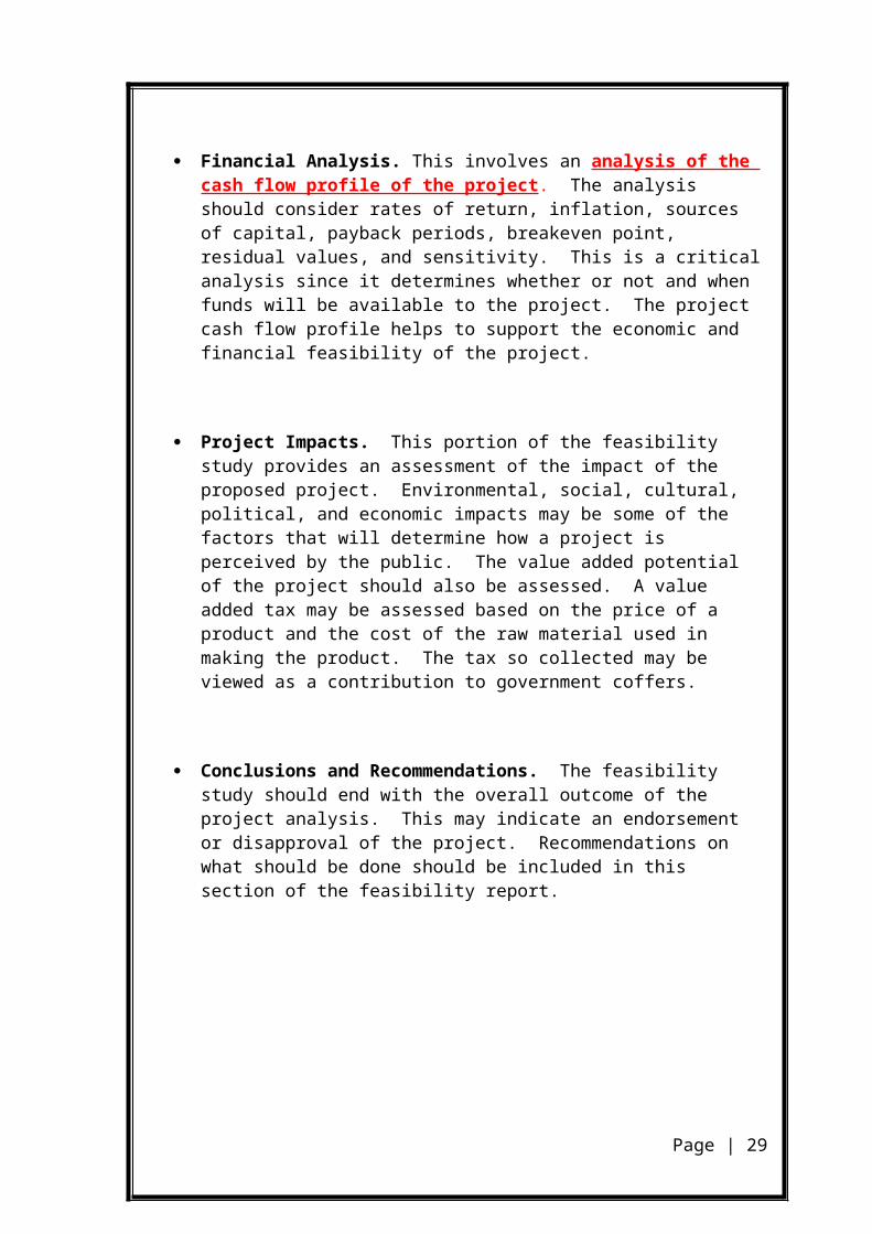
Financial Analysis. This involves an analysis of the cash flow profile of the project. The analysis should consider rates of return, inflation, sources of capital, payback periods, breakeven point, residual values, and sensitivity. This is a critical analysis since it determines whether or not and when funds will be available to the project. The project cash flow profile helps to support the economic and financial feasibility of the project.
Project Impacts. This portion of the feasibility study provides an assessment of the impact of the proposed project. Environmental, social, cultural, political, and economic impacts may be some of the factors that will determine how a project is perceived by the public. The value added potential of the project should also be assessed. A value added tax may be assessed based on the price of a product and the cost of the raw material used in making the product. The tax so collected may be viewed as a contribution to government coffers.
Conclusions and Recommendations. The feasibility study should end with the overall outcome of the project analysis. This may indicate an endorsement or disapproval of the project. Recommendations on what should be done should be included in this section of the feasibility report.
Page | 20
SOFTWARE REQUIREMENTS
SPECIFICATION
3.1 USER CHARACTERISTICS
The customer are the user of this product who have the right to
access this software. This ability is given through card no and Pin no. These users
are sure to be literate with the computers.
3.2 REQUIREMENT SPECIFICATION
This is the set of activities that lead to the production of
requirements definition and requirement specification. In requirement engineering
first of all feasibility study, in this study we try to find out the need and
requirements of the customer. They are satisfied with our product and also happy
with our proposed system. We include the personnel assignments, costs, project
schedule, and target date. This helps us to go ahead with our project.
Page | 21
Requirement definition is the most crucial part of the project.
Incorrect, inaccurate, or excessive definition of requirements must necessarily
result in schedule delays, wasted resources, or customer dissatisfaction.
The basic document that is needed is called Requirement
Specification. In other words a description of what you want the system to do.
This document may also be called a Business Needs Specification. The product
helps to find the user what he wants. He can register as a user in this site and he
can use all provisions of the system. Our customers are the persons who all are
satisfied with our product and who all can use this very easily for their serve.
Anyone can use the site. Those who want to search products and need products can
use this site as registered user or a search user. This site is user friendly. All the
commands and paths are given to this site. This helps a user to go ahead with his
goal. If a user wants to buy or sell a product, he must register to this site. He can go
ahead only after the administrator approves him as registered user.
Sometimes the requirement definition is presented as an
introduction to requirement specification. There are five requirements that a
software requirement document should satisfy,
It should specify external behavior
It should specify constraints on the implementation
It should be easy to change
It should serve as a reference tool
It should record throughout the life cycle
There are two types of requirements:
FUNCTIONAL REQUIREMENT
NON FUNCTIONAL REQUIREMENT
3.3 FUNCTIONAL REQUIREMENTS
Page | 22
Functional requirement describes the relationship between the input and
the output of the system. The functional requirements of the project are given
below.
OPERATOR
The ‘OPERATOR module consists of the following functions.
SWITCH ON ATM MACHINE
SWITCH OF ATM MACHINE
DEPOSIT THE MONEY FROM BANKS TO ATM
SWITCH ON ATM MACHINE
This option is for switching on an ATM MACHINE. After
switching on it will be available for customer. For this operator have to enter ATM
identification number and its password. The system will show appropriate message
in reply.
SWITCHING OFF ATM MACHINE
This is for switching off ATM machine. The system will show
appropriate message in reply.
DEPOSIT THE MONEY FROM BANK TO ATM
This is to supply the money to ATM for customer transaction. It
is a regular process .For this operator needs operator id, operator password, bank id
From where transaction is performed ,
Page | 23
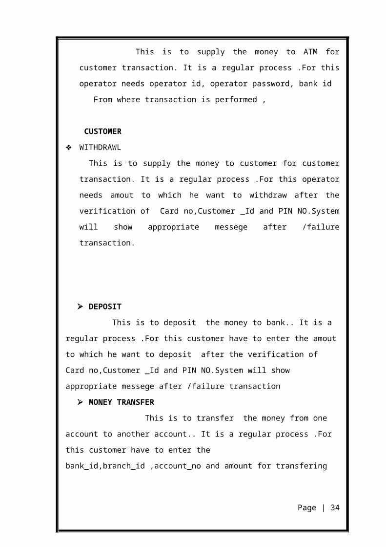
CUSTOMER
WITHDRAWL
This is to supply the money to customer for customer transaction. It is a regular
process .For this operator needs amout to which he want to withdraw after the
verification of Card no,Customer _Id and PIN NO.System will show appropriate
messege after /failure transaction.
DEPOSIT
This is to deposit the money to bank.. It is a regular process .For this
customer have to enter the amout to which he want to deposit after the verification of
Card no,Customer _Id and PIN NO.System will show appropriate messege after /failure
transaction
MONEY TRANSFER
This is to transfer the money from one account to another account.. It is a
regular process .For this customer have to enter the bank_id,branch_id ,account_no and
amount for transfering account.System will show appropriate messege after /failure
transaction
PIN NUMBER CHANGE
This is to change the pin number of corresponding account. .For this
customer have to enter the old PIN NO,new PIN NO,and CONFIRM PIN NO.
System will show appropriate messege after /failure transaction
MINI STATEMENT
This is to show the transaction currenty occured.For this customer
have to enter the PIN NO.System will show appropriate messege after /failure
transaction
BALANCE ENQUIRY
This is to show the current balance of account.For this customer
have to enter the PIN NO.System will show appropriate messege after /failure
Page | 24
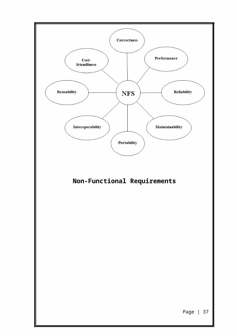
NON-FUNCTIONAL REQUIREMENTS
Nonfunctional requirements define system properties and
constraints it arises through user needs, because of budget constraints or
organizational policies, or due to the external factors such as safety regulations,
privacy registration and so on. Nonfunctional requirements are:
Security
Reliability
Maintainability
Portability
Extensibility
Reusability
Application Affinity/Compatibility
Resource Utilization
Page | 25
Non-Functional Requirements
Page | 26
SOFTWARE QUALITY ASSURANCE
PLAN
Page | 27
4.1 PURPOSE
The purpose of this plan is to define the “Customer Relationship
Management” Software Quality Assurance (SQA) organization, SQA tasks and
responsibilities; provide reference documents and guidelines to perform the SQA
activities; provide the standards, practices and conventions used in carrying out
SQA activities; and provide the tools, techniques, and methodologies to support
SQA activities, and SQA reporting.
4.2 SCOPE
The scope of this document is to outline all procedures,
techniques and tools to be used for quality assurance of this project.
This plan:
Identifies the SQA responsibilities of the project developer and the SQA consultant
Lists the activities, processes, and work products that the SQA consultant will review and audit
Identifies the SQA work products
.
4.3 OVERVIEW OF THE DOCUMENT
The rest of the document is organized as follows:
Management: A description of each major element of the organization and a
description of the SQA tasks and their relationships
Documentation: Identification of the documents related to development, verification,
validation, use and maintenance of the software.
Page | 28
SQAP Requirements: This section defines the SQA review, reporting, and auditing
procedures used to ensure that software deliverables are developed in accordance
with this plan and the project’s requirements.
4.3.1 Management
This section describes the management organizational structure,
its roles and responsibilities, and the software quality tasks to be performed.
4.3.2 Organization
Efforts for this project are supported by numerous entities,
organizations and personnel. This tool is developed as part of partial fulfillment of
requirements for Masters in Computer Applications degree. It will be the sole
responsibility of the developer to review the product’s usability, efficiency,
reliability, and accuracy. The client will however conduct inspections, reviews, and
walk-through on a regular basis. Client’s specifications and suggestions will be
used in places where quality decisions need to out-weigh development schedule
decisions.
4.3 TASKS AND RESPONSIBILITIES
Develop the requirement specification and cost estimation for the project
Develop the design plan and test plan for testing the tool
Implement and test the application and deliver the application along
with the necessary documentation
Give a formal presentation to the client on completion of the analysis,
design and testing phases. The client reviews the work and provides
feedback/suggestions.
Page | 29
Planning, coordinating, testing and assessing all aspects of quality
issues.
The responsibilities of the client are to:
Review the work performed.
Provide feedback and advice.
4.5 SQA IMPLEMENTATION IN DIFFERENT
PHASES
Quality assurance will be implemented through all the software
life cycles of the tool’s development process, until the release of the software
product. The following are the quality assurance tasks for each phase of the
software development:
Requirements phase: When the SRS is being developed, it has to be ensured that it
elucidates the proposed functionality of the product and to keep refining the SRS
until the requirements are clearly stated and understood.
Specification and Design phase: Due to the great importance for accuracy and
completeness in these documents, weekly reviews shall be conducted between the
developer and the client to identify any defects and rectify them.
Implementation phase: The developer shall do code reviews when the construction
phase of the Tool begins.
Page | 30

Software testing phase: The developer shall test each case. The final product shall
be verified with the functionality of the software as specified in the Software
Requirements Specification (SRS) for the Tool.
4.6 DOCUMENTATION
In addition to this document, the essential documentation will include:
The Software Requirements Specification (SRS), which
Prescribes each of the essential requirements (functions, performances,
design constraints and attributes) of the software and external interfaces
Objectively verifies achievement of each requirement by a prescribed
method (e.g. Inspection, analysis, demonstration or test)
Facilitates traceability of requirements specification to product delivery.
Gives estimates of the cost/effort for developing the product including a
project plan.
The Software Design Document (SDD)
Depicts how the software will be structured
Describes the components and sub-components of the software design,
including various packages and frameworks, if any.
Gives an object model that is developed using Rational Rose
highlighting the essential classes that would make up the product.
Gives a sample interaction diagram, showing the key interactions in the
application. This should also be a part of the object model.
Software Test Plan: Describes the test cases that will be employed to test the
product.
Page | 31
4.7 SOFTWARE DOCUMENTATION AUDIT
Quality Assurance for this project will include at least one
review of all current work products in each stage of development (Requirement,
Design, and Implementation). The reviews will assure that the established project
processes and procedures are being followed effectively, and exposures and risks
to the current project plan are identified and addressed. The review process
includes:
A formal presentation at the end of each development phase
(Requirement, Design and Implementation). All current work products
are presented to the client for review.
A managerial review by the client periodically to ensure the work
generated is in compliance with project requirements.
Reviews by the client after each presentation.
4.8 REQUIREMENTS TRACEABILITY
The SRS will be used to check off the deliverables. The Project
Review will ensure that each of the requirements mentioned in the SRS is met by
the deliverables.
4.9 SOFTWARE DEVELOPMENT PROCESS
The software development process involves three stages: 1)
Requirements phase, 2) Design phase 3) Implementation and testing phase. During
each phase, the client will review the deliverable documents. The developer would
Page | 32

incorporate modifications suggested by the committee. This would ensure quality
of the software product.
4.10 PROJECT REVIEWS
The client will perform a review at the 3 stages of the project as
described in the section above. This review will determine whether the
requirements have been met for the deliverable, check that the product meets the
requirements, ensure that the SQA plan has been adhered to, verify the
performance of the software and ensure that acceptance testing is carried out. A
design checklist will be used and the developer will check to see whether the
design meets the checklist criteria.
4.11 TESTING AND QUALITY CHECK
Testing will be carried out in accordance with the Software
Testing Plan (STP). Testing documentation will be sufficient to demonstrate that
testing objectives and software requirements have been met. Test results will be
documented and discussed in the final phase of the project.
Page | 33
SYSTEM DESIGN
Page | 34

1. SYSTEM DESIGN
System design provides the understanding and procedural details
necessary for implementing the system recommended in the system study.
Emphasis is on translating the performance requirements into design specifications.
The Design phase is a transition from a user-oriented document (system proposal)
to a documented oriented to the programmers or database personnel.
Systems design is the process or art of defining the architecture,
components, modules, interfaces, and data for a system to satisfy
specified requirements. One could see it as the application of systems
theory to product development.
This project has to design and implement a software for the
purpose of preparing cashbook. The system must be designed to retrieve from a
database browser and display the results in a formatted manner. Any modifications
to the data must also be done through an interface provided by the browser.
5.1 ARCHITECTURAL DESIGN
It defines the relationship between major structural elements of
the program. This design representation the modular framework of a computer
program can be derived from the analysis models and the interaction of the
subsystems defined within the analysis models. The primary objective is to
develop a modular program structure and data structure, defining interfaces that
enable the conceptual view of software product. This means performing a number
of tasks that such as decomposing the specification into software modules,
Page | 35
indentifying the interfaces and interconnections among the functions and sub
functions, identifying the data used and passed among the functions and finally
identifying where data is stored.
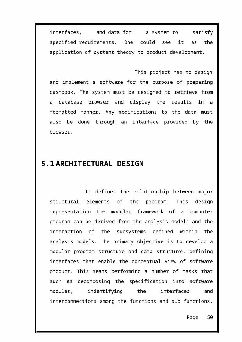
The basic architecture for the proposed system is like that
Presentation Layer: All the PHP and HTML pages are designed in this tier.
Business Layer: All the business logic and service code are written here.
DAO Layer: All the database connections and resultset related codes are written here.
5.2 PROCESS DESIGN
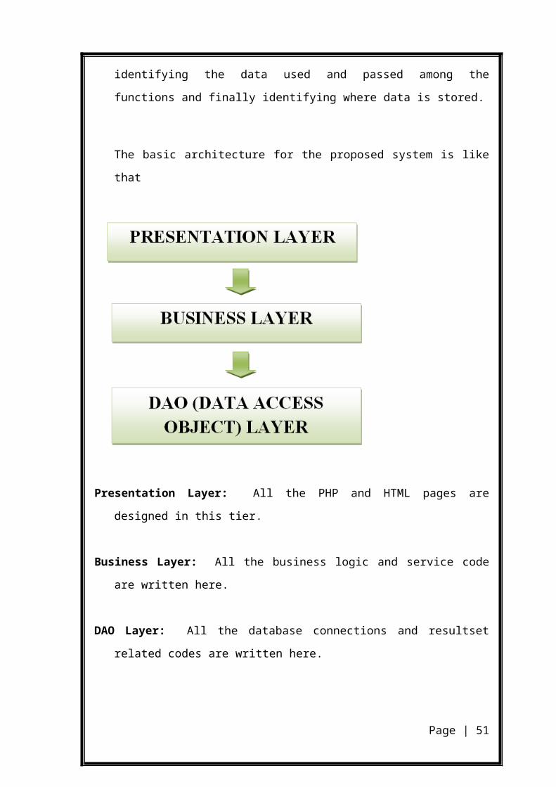
V-MODEL OF DEVELOPMENT
V Process is a whole life-cycle process. V process must be applied at
each stage in the software process.
Page | 36
OBJECTIVE
The V_Model (Lifecycle Process Model) regulates the system
development process and the maintenance and modification of systems.
This standard helps to achieve the following objectives:
Improvement and guarantee of the quality:
- The discovery of defects in a system.
- The assessment of whether or not the system is usable in an operational situation.
- The completeness of the results to be delivered can best be guaranteed by a
standardized procedure.
- Defined interim results make early assessment procedures possible. Uniform
product contents alleviate the readability of the products and the assessment
procedures.
Checking the costs for the whole lifecycle:
- The generation of relevant project-specific development standards and its
assessment will be simplified.
Page | 37
- The standardized procedure makes the cost calculation more transparent. Any risks
in connection with the costs can be recognized better.
- Uniform standards reduce friction losses between customer and contractor as well
as between main contractor and subcontractor.
- Standardized procedures allow for the reduction in the use of resources.
- In case of a standardized procedure universal approaches to the solutions become
transparent and can thus be used.
- Undesirable developments are recognized ataan earlier stage.
- The training costs are reduced.
Improvement in the communication between the different parties, as well as a
reduction in the dependence of the customer on the contractor:
- Using defined terms reduces misunderstandings between all parties involved.
- The user, the purchaser, and the developer will be supported when formulating
their requirements/when describing their parts or results.
- The interim results/final results are standardized to such an extent that other parties
involved or staff of other companies are able to settle in without very much effort,
if necessary.
5.3 ENTITY RELATIONSHIP DIAGRAM
In order to make the physical design, the data is first analyzed
through ER (Entity Relationship) modeling technique. This technique emphasizes
that a database system for an application is made of entities. An entity is a
comprehensive real world object that can be identified. According to it, entities
have relationship with each other. An entity relationship diagram can represent
various entities of any system.
Entity Relationship Diagrams (ERDs) illustrate the logical
structure of databases.
Page | 38
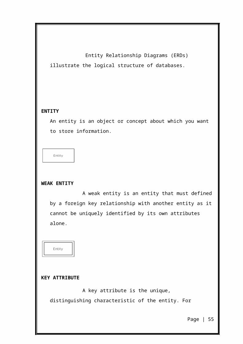
ENTITY
An entity is an object or concept about which you want to store information.
WEAK ENTITY
A weak entity is an entity that must defined by a foreign key relationship
with another entity as it cannot be uniquely identified by its own attributes alone.
KEY ATTRIBUTE
A key attribute is the unique, distinguishing characteristic of the entity.
For example, an employee's social security number might be the employee's key
attribute.
MULTIVALUED ATTRIBUTE
A multivalued attribute can have more than one value. For example, an
employee entity can have multiple skill values.
Page | 39
DERIVED ATTRIBUTE
A derived attribute is based on another attribute. For example, an
employee's monthly salary is based on the employee's annual salary.
RELATIONSHIPS
Relationships illustrate how two entities share information in the
database structure.
Page | 40
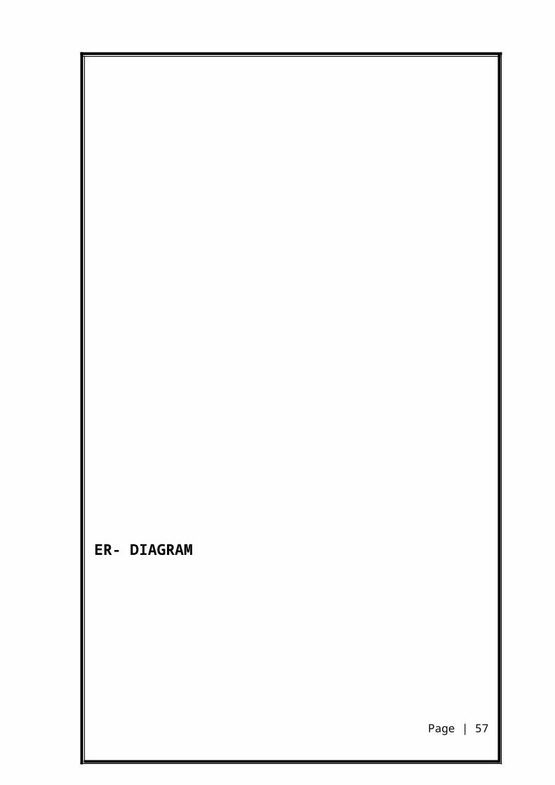
Relationship
ER- DIAGRAM
account
balance
account_info
branch
branch_name
customer
Line 2
City
name
depositer
branch_id
customer_secret account no
zero_nzero_x
card_nozero_r
zero_v
customer_id
branch_id
bank_id
bank
name
city
address
assets
atm
transaction
atm_id
password placeassets
place
secret
rsa_secrsa_num
rsa_exp
card_no
amounttran_date
branch_id
tran_time
tran_id
bankId
status
tran_mode
operator
operator_id
password block
datecard_id
Edraw Trial Version
Edraw Trial Version
Edraw Trial Version
Page | 41
DATA DESIGN
6.1 DATA FLOW DIAGRAM
A data flow diagram is a graphical technique that depicts
information flow and transforms that are applied as data move from input to
output. The DFD is used to represent increasing information flow and functional
details. A level 0 DFD, also called fundamental system model or a Context model,
represents the entire software elements as a single bubble with input and output
indicated by incoming and outgoing arrows respectively. Additional process and
information flow parts are represented in the next level i.e., Level 1 DFD. Each of
the processes represented at Level 1 are sub functions of overall system depicted in
the Context model. Any processes, which are complex in Level 1, will be further
represented into sub functions in next level, i.e., in Level 2.
Data flow diagrams illustrate how data is processed by a system in terms of
inputs and outputs. Represents major components or functions with circles
Actions for input by user or system go in rectangular boxes
Databases are represented by parallel lines enclosing a phrase corner
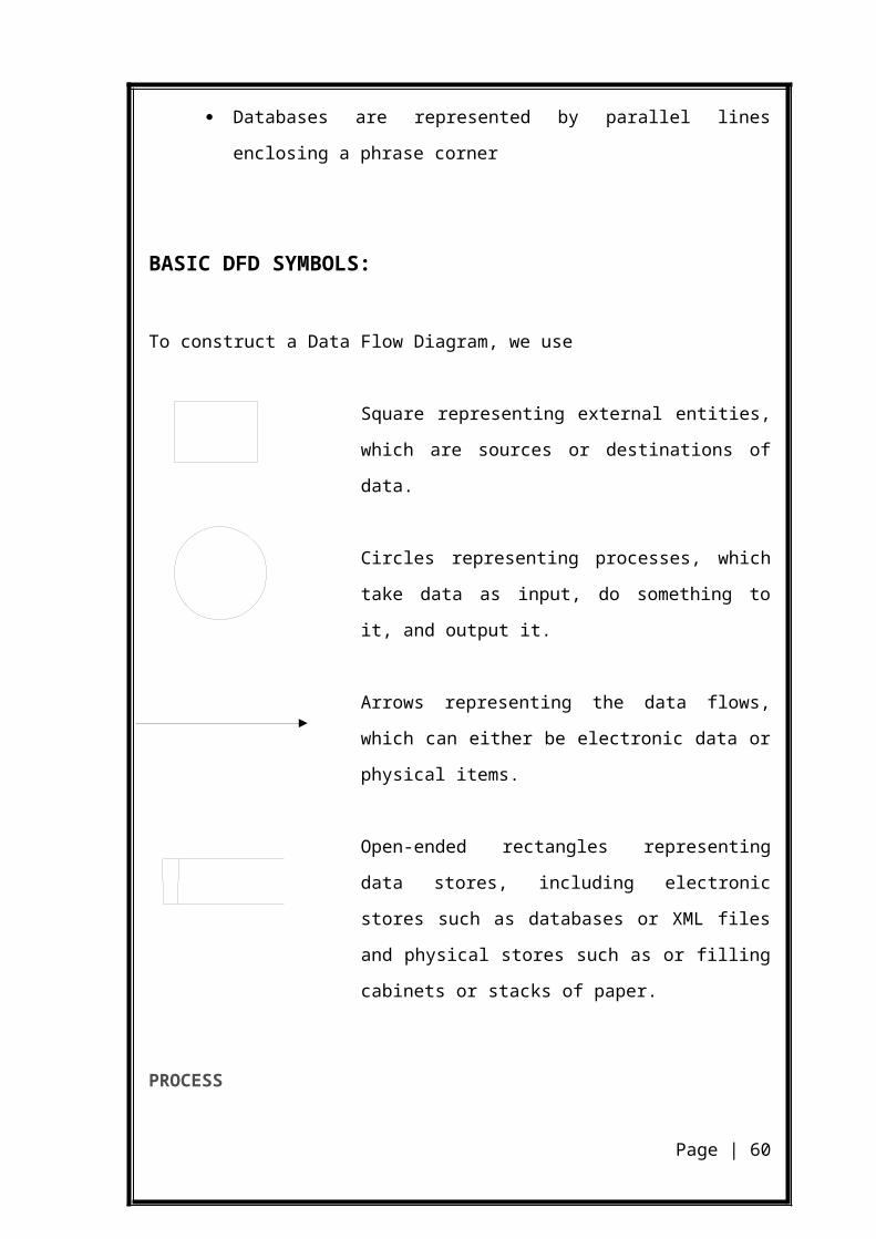
BASIC DFD SYMBOLS:
To construct a Data Flow Diagram, we use
Square representing external entities, which are sources
or destinations of data.
Circles representing processes, which take data as input,
do something to it, and output it.
Page | 42
Arrows representing the data flows, which can either be
electronic data or physical items.
Open-ended rectangles representing data stores, including
electronic stores such as databases or XML files and
physical stores such as or filling cabinets or stacks of
paper.
PROCESS
The process shape represents a task that handles data within the
application. The task may process the data or perform an action based on the data.
MULTIPLE PROCESS
The multiple process shape is used to present a collection of sub processes.
The multiple process can be broken down into its sub processes in another DFD.
EXTERNAL ENTITY
The external entity shape is used to represent any entity outside the
application that interacts with the application via an entry point.
DATA FLOW
The data flow shape represents data movement within the application. The
direction of the data movement is represented by the arrow.
DATA STORE
The data store shape is used to represent locations where data is stored.
Data stores do not modify the data, they only store data.
PRIVILEGE BOUNDARY
Page | 43

CUSTOMER ATM
The privilege boundary shape is used to represent the change of privilege
levels as the data flows through the application.
DATA FLOW DIAGRAM LAYERS
Draw data flow diagram in several nested layers. A single
process node on a high level diagram can be expanded to show a more detailed
data flow diagram. Draw the context diagram first, followed by various layers of
data flow diagrams.
LEVEL 0 :- (CONTEXT DIAGRAM)
REQUEST OUERY FOR REQUEST
DATABASE
RESULT QUEOY FOR
RESULT
Page | 44
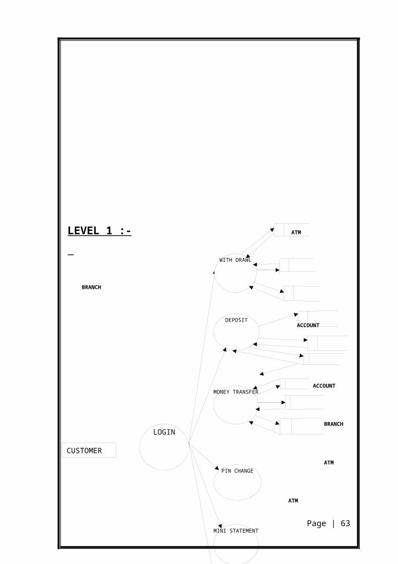
CUSTOMER
LOGIN
WITH DRAWL
DEPOSIT
MONEY TRANSFER
PIN CHANGE
MINI STATEMENT
BALANCE ENQUIRY
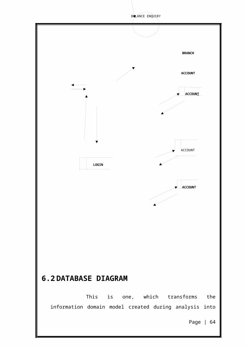
LEVEL 1 :- ATM
BRANCH
ACCOUNT
ACCOUNT
BRANCH
ATM
ATM
BRANCH
ACCOUNT
ACCOUNT
ACCOUNT
LOGIN
ACCOUNT
Page | 45

6.2 DATABASE DIAGRAM
This is one, which transforms the information domain model
created during analysis into one, data structures that will implement the software.
The primary activity during this design is to select logical representations of data
objects identified during the requirement definition and specification phase. The
main tables required for the software are identified during the analysis phase. The
tables are designed in such a way so as to store information efficiently and avoid
unnecessary redundancy, yet making the retrieval of data easier. Above all,
catering to the needs of the application, the database is normalized.
The advantages of normalization are:
To structure the data so that any pertinent relationships between the
entities can be represented.
To permit retrieval of data in response to query and report requests.
To simplify the maintenance of data through updations, insertions and
deletions.
To reduce the need to restructure or recognize data when a new
application requirements arise.
The database is to be protected from accidental destruction. The
organization of the database should be such that it achieves data integrity and data
independence
NORMALIZATION
Normalization provides for table optimization through the
investigation of entity relationships. Main purpose of normalization is to avoid
Page | 46
Data redundancy and some unforeseen scalability factors. Normalization is done to
remove Insertion, Updating and Modification anomalies and redundancy of data. A
certain level of normalization of tables in database gives a particular normal form
based of particulars steps followed. Database can be normalized up to any defined
normal forms according as the need of application and its effectiveness.
Database of this project is normalized up to Second Normal
Form. Further normalization of database was not considered taking into account
the need of application and ease of working with database.
The database is in First Normal Form as all the fields of all tables are atomic.
There is no multivalued field in any table.
The database is in Second Normal Form as it satisfies the constraint of full
functional dependency. All the fields of all tables are fully functional dependent on
the primary key.
OPERATOR
FIELD NAME TYPE NULL KEY
ID VARCHAR(20) NO PRIMARY
PASSWORD VARCHAR(20) NO
BANK
FIELD NAME TYPE NULL KEY
BANK_ID VARCHAR(10) NO PRIMARY
BANK_NAME VARCHAR(20) NO
Page | 47
BRANCH
FIELD NAME TYPE NULL KEYBRANCH_ID VARCHAR(10) NO PRIMARY
BANK_ID VARCHAR(10) NO FOREIGN
BRANCH_NAME VARCHAR(30) NO
CITY VARCHAR(30) NO
ADDRESS VARCHAR(30) NO
ACCOUNT
FIELD NAME TYPE NULL KEY
ACCOUNT_NO VARCHAR(30) NO PRIMARY
CARD_NO VARCHAR(30) NO
BRANCH_ID VARCHAR(20) NO FOREIGN
BALANCE VARCHAR(20) NO
ACCOUNT_INFO VARCHAR(20) NO
Page | 48

CUSTOMER
FIELD NAME TYPE NULL KEYCUSTOMER_ID VARCHAR(30) NO PRIMARY
CUSTOMER_NAME VARCHAR(30) NO
CITY VARCHAR(30) NO
ADDRESS VARCHAR(30)
DEPOSITER
FIELD NAME TYPE NULL KEY
ACCOUNT_ID VARCHAR(30) NO FOREIGN
CUSTOMER_ID VARCHAR(30) NO FOREIGN
ATM
FIELD NAME TYPE NULL KEY
ATM_ID VARCHAR(30) NO PRIMARY
BANK_ID VARCHAR(10) NO FOREIGN
ASSETS DOUBLE NO
PLACE VARCHAR(30) NO
STATUS VARCHAR(10) NO
PASSWORD VARCHAR(10) NO
Page | 49
CUSTOMER_SECRET
FIELD NAME TYPE NULL KEY
ACCOUNT_NO VARCHAR(20) NO FOREIGN
CARD_NO VARCHAR(10) NO PRIMARY
ZERO_N BIGINT NO
ZERO_X BIGINT NO
ZERO_V BIGINT NO
ZERO_R BIGINT NO
SECRET
FIELD NAME TYPE NULL KEY
BANK_ID VARCHAR(20) NO FOREIGN
BRANCH_ID VARCHAR(20) NO PRIMARY
RSA_PUB BIGINT
RSA_SECRET BIGINT
RSA_EXP INT
Page | 50
TRANSACTION
FIELD NAME TYPE NULL KEYTRANS_ID VARCHAR(30) NO PRIMARYATM_ID VARCHAR(10) NO FOREIGN
PINID VARCHAR(30) NO
AMOUNT VARCHAR(20) NO
STATUS VARCHAR(30) NO
BANK_ID VARCHAR(10) YES
BRANCH_ID VARCHAR(20) YES
TRAN_DATE DATE NO
TRAN_TIME TIME NO
MODE VARCHAR(20) NO
BLOCK_ID
FIELD NAME TYPE NULL KEYCARD_ID VARCHAR(30) NO
DATE DATE NO
Page | 51
SYSTEM TESTING
7. SYSTEM TESTING
Testing is the penultimate step of software development. An
elaborate testing of the data is prepared and the system is using the test data.
While doing testing, errors are noted and correction is made. The users are
trained to operate the developed system. Both hardware and software securities
are made to run the developed system successfully.
System testing is aimed at ensuring the system works
accurately before the live operation commences. Testing is vital to the system.
System testing makes a logical assumption that if all parts of the system are
correct, the goal will be successfully achieved. The Proposal Tracking system
is subjected to a variety of tests; unit testing, integration testing and system
testing. A series of testing are performed for the proposed system before the
system is ready for user acceptance testing. Nothing is complete without
testing, as it is vital success of the system.
Normally, testing of any Large Systems will be in TWO parts.
The functional verification and validation against the Requirement Specification
and Performance evaluation against the indicated requirements. Testing activity is
involved right from the beginning of the project.
At the very first stage of testing, the goals and objectives are set.
This simplifies the limits or borders of testing process. Before testing, the tester
should plan what kind of data he is giving for test. Give data inputs as functional,
boundary, stress, performance, usability values etc.
Characteristics of a Good Test:
Tests are likely to catch bugs
Page | 52
No redundancy
Not too simple or too complex
Psychology of Testing
The aim of testing is often to demonstrate that a program works
by showing that it has no errors. The basic purpose of testing phase is to detect the
errors that may be present in the program. Testing is the process of executing a
program with the intent of finding errors.
TESTING OBJECTIVES
The main objective of testing is to uncover a host of errors,
systematically and with minimum effort and time.
Testing is a process of executing a program with the intent of finding an
error.
A successful test is one that uncovers an as yet undiscovered error.
A good test case is one that has a high probability of finding error, if it
exists.
The tests are inadequate to detect possibly present errors.
The software more or less confirms to the quality and reliable standards
7.1 LEVELS OF TESTING
Testing is usually relying on to detect the faults on each phase, in
addition to the faults introduced during the coding phase itself. Due to this,
different levels of testing are used in the testing process, each level of testing aims
to test different aspect of a system.
In order to uncover the errors present in different phases we have
the concept of levels of testing. The basic levels of testing are
Page | 53
Client Needs : Acceptance Testing
Requirements : System Testing
Design : Integration Testing
Code : Unit Testing
WHITE BOX TESTING
This is a unit testing method where a unit will be taken at a time
and tested thoroughly at a statement level to find the maximum possible errors.
I tested step wise every piece of code, taking care that every
statement in the code is executed at least once. The white box testing is also called
Glass Box Testing.
Page | 54
Client
Requirements
Design
Code Unit Testing
Integration Testing
System Testing
Acceptance
I have generated a list of test cases, sample data which is used to
check all possible combinations of execution paths through the code at every
module level. In this testing to test the code we use one method known as Black
box testing.
BLACK BOX TESTING
This testing method focuses on the functional requirements of
the software. Here each module will be treated as a black box that will take some
input and generate output. Output for a given set of input combinations are
forwarded to other modules.
Black box testing attempts to find the following types of errors:
Incorrect or missing functions.
Interface errors.
Errors in data structures or external database access.
Performance errors
Initialization errors and termination errors.
All the forms have been executed and verified. Based on some
sample input data, the generated output is verified whether the system is providing
better results or not.
STRATEGIC APPROACH TO SOFTWARE TESTING
The software engineering process can be viewed as a spiral.
Initially, system engineering defines the role of software and leads to software
requirement analysis where the information domain, functions, behavior,
performance, constraints and validation criteria for software are established.
Moving inward along the spiral, we come to design and finally to coding. To
Page | 55

develop computer software we spiral in along streamlines that decrease the level of
abstraction on each turn.
A strategy for software testing may also be viewed in the context
of the spiral. Unit testing begins at the vertex of the spiral and concentrates on each
unit of the software as implemented in source code. Testing progresses by moving
outward along the spiral to integration testing, where the focus is on the design and
the construction of the software architecture. Taking another turn on outward on
the spiral we encounter validation testing where requirements established as part of
software requirements analysis are validated against the software that has been
constructed. Finally we arrive at system testing, where the software and other
system elements are tested as a whole.
Table given below outlines the tests that were performed on the
system to ensure correctness and unearth errors, which were subsequently
debugged.
Table shows the Tests Conducted on the System
Testing Phase Objectives
Unit Testing
The various functions within each program and the program
blocks are tested for proper working.
Module Testing
A module is composed of various programs related to that
module. Module testing is done to check the module
functionality and interaction between units within a module.
Integration Testing
Integration testing is done to test the functionality and interfacing
between the modules.
Acceptance Testing
Acceptance testing is done after implementation to check if the
system runs successfully in the environment/site.
Page | 56
UNIT TESTING
Unit Testing will be done to test field validations, navigation,
functionality of the programs and its block. These tests are applied on various
functions within each program and other critical program blocks. Table given
below gives the outline of three-sample test cases for Unit Testing performed on
the system.
Table Unit Testing – Test Case
Test Case Description
This test case deals with the entering of basic details related with the logged in
administrator. This process takes many inputs. The test case should check for proper
inputs and verify whether the function for validating the inputs is called properly or
not.
Inputs
Details Related with the logged in administrator in a Standard Format.
Expected Outputs
Alert window for erroneous inputs.
Confirmation of Successful Completion of basic details entry process.
Actual Test Results
An alert window was shown whenever the user gave some erroneous data.
Confirmation of completion of basic details entry was displayed on submission,
implying that the functions were called properly.
MODULE TESTING
Page | 57

Module Testing will be done to test the interaction between the
various programs within one module. It checks the functionality of each program
with relation to other programs within the same module. It then tests the overall
functionality of each module.
INTEGRATION TESTING
The major concerns of integration testing are developing an
incremental strategy that will limit the complexity of entire actions among
components as they are added to the system. Developing a component as they are
added to the system, developing an implementation and integration schedules that
will make the modules available when needed, and designing test cases that will
demonstrate the viability of the evolving system. Though each program works
individually they should work after linking them together. This is also referred to
as interfacing. Data may be lost across interface and one module can have adverse
effect on another. Subroutines after linking may not do the desired function
expected by the main routine. Integration testing is a systematic technique for
constructing program structure while at the same time conducting tests to uncover
errors associated with the interface. In the testing, the programs are constructed and
tested in small segments.
VALIDATION TESTING
This provides the final assurance that the software meets all the
functional, behavioral and performance requirements. The software is completely
assembled as a package. Validation succeeds when the software functions in a
manner in which user wishes. Validation refers to the process of using software in
live environment in order to find errors. During the course of validation the system
failure may occur and sometime the coding has to be hanged according to the
requirement. Thus the feedback from the validation phase generally produces
changes in the software.
Page | 58
Once the application was made of all logical and interface errors,
inputting dummy data ensure that the software developed satisfied all the
requirements of the user. The dummy data is known as test cases.
OUTPUT TESTING
After performing the validation testing, the next step is output
testing of the proposed system since no system could be useful if it does not
produce the required output in the specific format. Asking the users about the
format of output they required, tests the output generated in two ways. One is on
screen and another is printed format.
The output format on the screen found to be correct a s the
format was designed in the system design phase according to the user needs. For
the hard copy also, the output comes out as the specified requirement by the user.
Hence output testing does not result in any correction in the system.
ACCEPTANCE TESTING
Acceptance testing (also known as user acceptance testing) is a
type of testing carried out in order to verify if the product is developed as per the
standards and specified criteria and meets all the requirements specified by
customer. This type of testing is generally carried out by a user/customer where the
product is developed externally by another party.
Acceptance testing falls under black box testing methodology
where the user is not very much interested in internal working/coding of the
system, but evaluates the overall functioning of the system and compares it with
the requirements specified by them. User acceptance testing is considered to be one
of the most important testing by user before the system is finally delivered or
Page | 59
handled over to the end user.
Acceptance testing is also known as validation testing, final testing,
QA testing, factory acceptance testing and application testing etc. And in software
engineering, acceptance testing may be carried out at two different levels; one at
the system provider level and another at the end user level (hence called user
acceptance testing, field acceptance testing or end-user testing).
Acceptance test refers to the acceptance of data into the system for
processing. The acceptance test contributes to the consistency and smooth working
of the system. The system under consideration is tested for users at a time for
developing and making changes whenever required. This is done with regard to the
following points :
Screen design
Output screen design
On-line message to guide the user
SYSTEM TESTING
When a system is developed, it is hoped that it performs
properly. In practice however some errors always occur. The main purpose of
testing and information system is to find the errors and correct them. A successful
test is one which finds an error.
The main objectives of system testing are:
To ensure during operation the system will perform as per
specifications.
To make sure that the system meets the requirements during operation.
To verify that the controls incorporated in the system function as
intended.
Page | 60
To see that when correct inputs are fed to the system the outputs are
correct.
To make sure that during operation incorrect input and output will be
deleted.
The scope of a system test should include both manual
operations and computerized. Operation system testing is a comprehensive
evaluation of the programs, manual procedures, computer operations and controls.
System testing is the process of checking if the developed system is working
according to the original objectives and requirements. All testing needs to be
conducted in accordance to the test conditions specified earlier.
7.2 TEST CASES
A specific set of steps and data along with expected results for a
particular test objective. A test case should only test one limited subset of a feature or
functionality.
Cash Book has used so many such test cases.
Test case
Description Expected Result Pass/Fail
Actual Result
OFF/ON STATE
1. Enter ID and PasswordAnd click on “SUBMIT”
Make sure ‘Home’Page should appear
Pass ‘Home’ page appears
2. Without providing ATM_id, click on “submit”
Make sure error message should display as “Enter ATM_id ”
Pass Error Message is displayed
3. Without providing password, click on “submit”
Make sure error message should display as “Enter
Pass Error Message is displayed
Page | 61

Password”4. Enter invalid ATM_id in
the ATM_id field, and click on “submit”
Make sure error message should display as “Invalid ATM_id”
Pass Error Message is displayed
Enter wrong ATM_id-Password combination, and click on “submit”
Make sure error message should display as “ATM id/password is wrong.”
Pass Error Message is displayed
PIN NUMBER
1. Writing correct PIN number in PIN number field and click “submit”
Make sure ‘main page should be appear
Pass ‘Head of Account’ Page appears
2. Writing incorrect PIN number in PIN number field three times and click “submit”
Make sure ‘ATM card should should be blocked” appear
Pass Error Message is displayed
WITHDRAWL
1. Click on “WITHDRAW”
Make sure ‘WITHDRAW’ Page should appear
Pass ‘WITHDRAW’ Page appears
2. Click on “submit” after filling The amount field
Make sure ‘transaction will be successful’ Page should appear
Pass transaction will be successful appear
3. Click on “submit” after filling
Make sure message should display as
Pass Message is displayed
Page | 62
The amount field known this ATM has not much amount
“insufficient amount in ATM”
4. Click on “submit” after filling The amount field known this your account has not sufficient amount
Make sure message should display as “insufficient amount in your account”
Pass Error Message is displayed
5 Click on “submit” after filling The amount field greater than 25000
Make sure message should display as “cant allow more than 25000 in one times”
Pass Error Message is displayed
6 Click on “submit” after filling The amount field greater than 50000 in One day
Make sure message should display as “cant allow more than 50000 in one days”
DEPOSIT
1. Click on “DEPOSIT”
Make sure ‘DEPOSIT’ Page should appear
Pass ‘DEPOSIT’ Page appears
2. Click on “submit” after filling The amount field
Make sure ‘transaction will be successful’ Page should appear
Pass transaction will be successful appear
MONEY TRANSFER
1. Click on “money transfer”
Make sure ‘MONEY TRANSFER’ Page should appear
Pass ‘MONEY
TRANSFER’ Page appears
2. Click on “submit” after filling The amount,bank_id,branch_id,account
Make sure ‘transaction will be successful’ Page should appear
Pass transaction will be successful appear
Page | 63
&,amount field3. Click on
“submit” after filling The amount field known this account has not much amount
Make sure message should display as “insufficient amount in account”
Pass Message is displayed
PINMUMBER CHANGE1. Click on
“PIN number change”Make sure ‘PIN
NUMBER CHANGE’ Page should appear
Pass ‘PIN NUMBER
CHANGE’ Page appears
2. Click on “submit” after filling The old PIN no, new PIN no and confirmPIN no
Make sure ‘PIN number will be successful’ Page should appear
Pass PIN number change will be successful appear
3. Click on “submit” after filling Wrong old PIN number
Make sure error should display as “old PIN number is wrong”
Pass Error is displayed
4 Click on “submit” after filling Wrong confirm PIN number
Make sure error should display as “confirm PIN number is wrong”
Pass Error is displayed
MINI STATEMENT
1. Click on “MINI STATEMENT”
Make sure ‘MINI
STATEMENT “Page should appear
Pass MINISTATEMENT Page appears
Page | 64
BALANCE ENQUIRY
1. Click on “BALANCE ENQUIRY”
Make sure ‘BALANCE ENQUIRY “Page should appear
Pass “BALANCE ENQUIRY “Page appears
7.3 VALIDATION CHECKS
I have use following type of checks/ data validations:
Data type
Length
Constraints
Blank field
Format
Data type:
I have use Varchar type for character, int for numeric, Decimal for amount and
Date for date type. Character never inputted in numeric field as amount, no never
accept character if any person input wrongly.
Length:
When we define a max length, then it never accepts more data. For example, if I
define numeric length is 5, then it store either equal to length or less than length. If
user gives more character than required then it never accept.
Constraints:
In this I am defining range of data, if data is less than then display error with
message. For example, the field of date must be 8 characters.
Blank field:
Page | 65
Some fields need not to be blank. If the data needed field is blank then it display
message without halt.
Format:
The predefine format is used not change daily to daily. For example, format of date
DDMMYYYY is used in all date type field. If user inserts another format then it
never accepts.
SYSTEM IMPLEMENTATION
8. SYSTEM IMPLEMENTATION
A crucial phase in system development is the successful
implementation of the new system design. Implementation includes all those
activities that take place to convert from the old system to the new system. The
new system may be completely new replacing an existing manual or automated
system or it may be major modification to an existing system.
In either case proper implementation becomes necessary so that a
reliable system based on the requirement of the organization can be provided.
Successful implementation may not guarantee improvement in the organization
using the new system, but improper installation will prevent this improvement.
It has been observed that even the best system cannot show good
results if the analysts managing th implementation do not attend every important
detail. This is the area where the system analysts need to work with utmost care.
There are three main aspects of implementation:-
User training
User Manual
Conversion
Page | 66
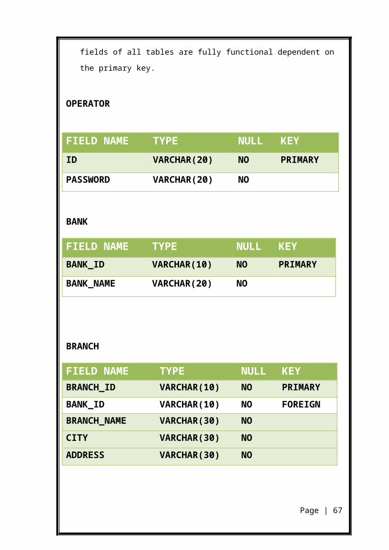
User Training
Even well designed system can succeed or fail because of the
way these are operated and used. Therefore the quality of training received by the
personal involved with the system in various capacities helps or hinders and may
even prevent with the system development must know in detail what their roles
will be, how they can make efficient use of the system and what will not do for
them.
An analysis of user training focuses on two factors:-
User capabilities
Nature of the proposed system
When a system is developed then only the developer of it knows
its operation. But as the project is being made for a client (organization) and it is to
be used by the employees of that firm, so there is need of user training. As the
system is new for the employees and staff of the cooperation so there is a necessity
to train them because they have to operate the system. For the live demonstration
with the personal contact are very effective. No training is complete without
familiarizing users with simple system.
User Manual
When a system is developed then only the developer of it knows
its operation. But as the project is being made for a client and it is to be used by the
staffs of that firm, so there is a need of user manual. It is documentation of project
that describes how to operate the system? What are the various modules for
efficient use of the system? How to start the system?
The user manual helps to find out the answers of the queries like:-
Page | 67
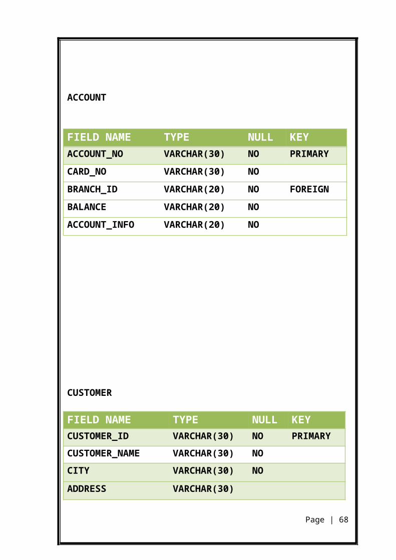
How to start the system?
How to make entry?
How to generate reports?
Conversion
Conversion is the process of the old system to the new one. It
should be accomplished in shortest possible time. Four methods are commonly
used:-
Parallel system
Direct conversion
Pilot system
Phase – in mind
The ATM SOFTWARE is being developed with different
phases being taken into mind….the project is developed in different phases starting
with the analysis phase and ends with implementation phase. After implementation
phase the maintenance phase will begin which keeps on going….
Page | 68

SYSTEM MAINTENANCE
9. SYSTEM MAINTENANCE
Page | 69
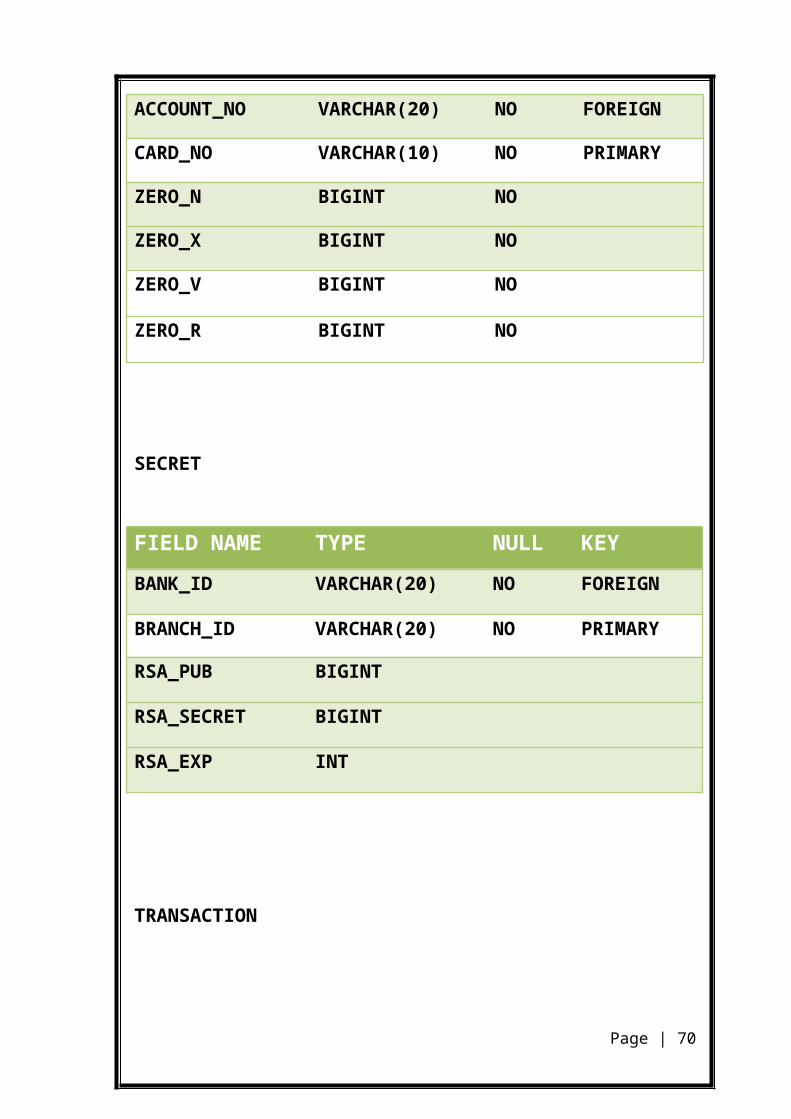
System maintenance is the modification of a software product
after delivery to correct faults, to improve performance or other attributes, or to
adapt the product to a modified environment. Maintenance is thus a very broad
activity often defined as including all work made on a software system after it
becomes operational.
Maintenance covers large number of activities like the correction
of errors, the enhancement, deletion and addition of capabilities, the adaptation to
changes in data requirements and operation environments, the improvement of
performance, usability, or any other quality attribute. Maintenance accounts for 50-
80 percent of total system development. To put maintenance in its proper
perspective requires considerable skill and experience and is an important and
ongoing aspect of system development. Maintenance demands more orientation
and training than any other programming activities. The environment must
recognize the needs of the maintenance programmer for tools, methods and
training.
Maintenance is done after the successful implementation of the
software and is continued till the product is reengineered or deployed to another
platform. Maintenance is also done based on fixing the problems reported,
changing the interface with other software or hardware enhancing the software.
Page | 70
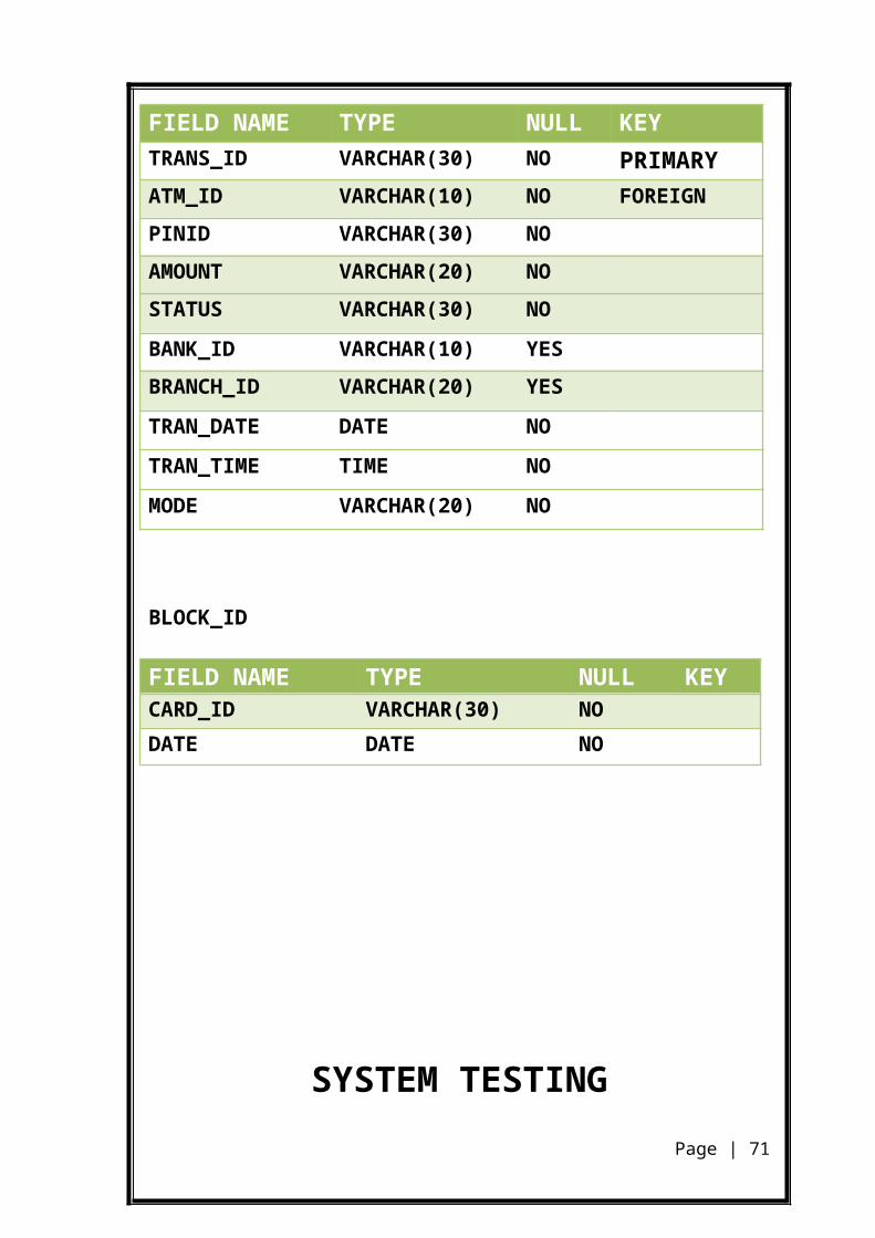
CONCLUSION
Page | 71
10. CONCLUSION
It is a user-friendly software and requires little prior knowledge
of software. All the suggestions forwarded during the software proposal have been
successfully completed and final threshold of application has been crossed. Some
errors were spotted out during the system testing and were corrected. The system
developed for the given conditions specified by the firm was found working
efficiently. The system is highly flexible and is well efficient to make easy
interactions with the database. The goal of computer security to maintain the
integrity, availability and privacy of information entrusted to the system was
successfully obtained. This system work best for the security of ATM money
transaction and other concurrency issue.By applying zero knowledge protocol no
body know what is customer PIN number even if administrator also.It provides
network level security by applying RSA public key algorithm & MD5/SHA
message digesting algorithm. so This will provide high level security.
Page | 72
SCREEN SHOTS
Page | 73
FIRST PAGE
Page | 74
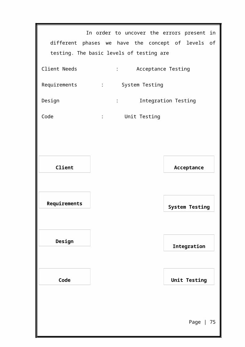
CARD READING PAGE
Page | 75
ENTER PIN NUMBER PAGE
Page | 76
SELECTION PAGE FOR SAVINNGS/CURRENT
Page | 77
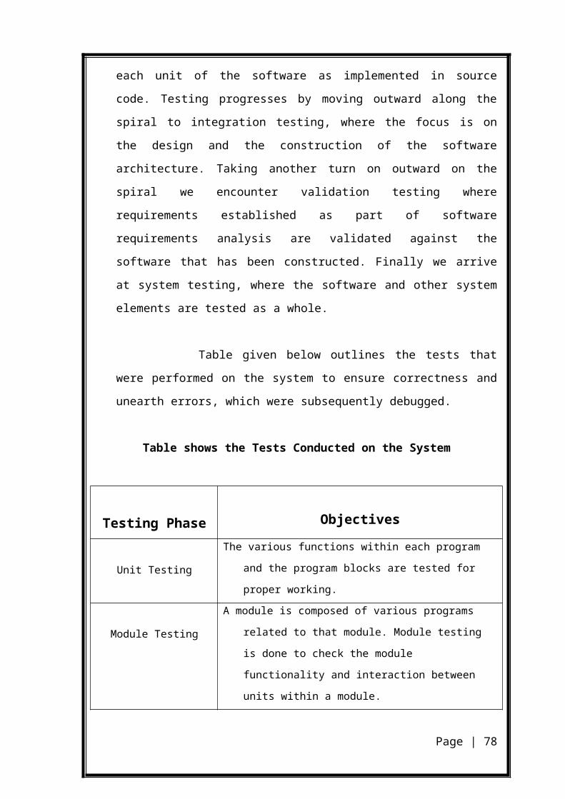
MAIN PAGE
Page | 78
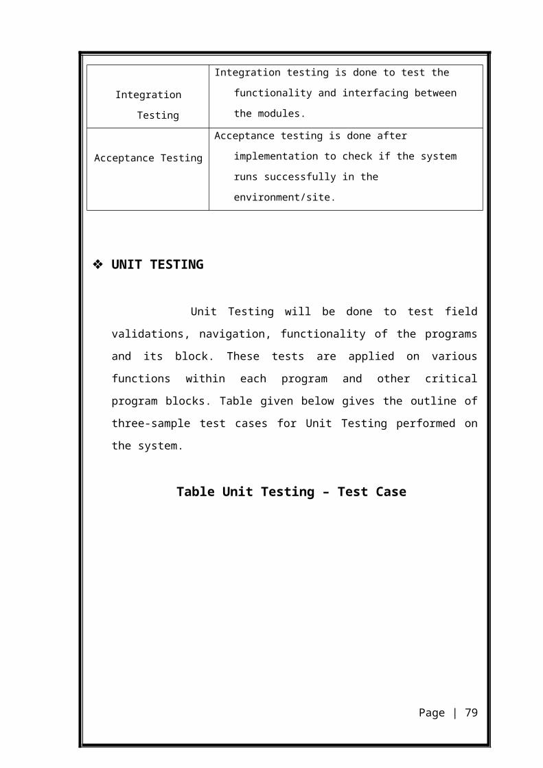
WITHDRAWL PAGE
Page | 79

WITHDRAWL OUTPUT PAGE
Page | 80
DEPOSIT OUTPUTPAGE
Page | 81
MONEY TRANSFER PAGE
Page | 82
MONEY TRANSFER OUTPUT PAGE
Page | 83
BALANCE ENQUIRY PAGE
Page | 84
PINCHANGE PAG
Page | 85
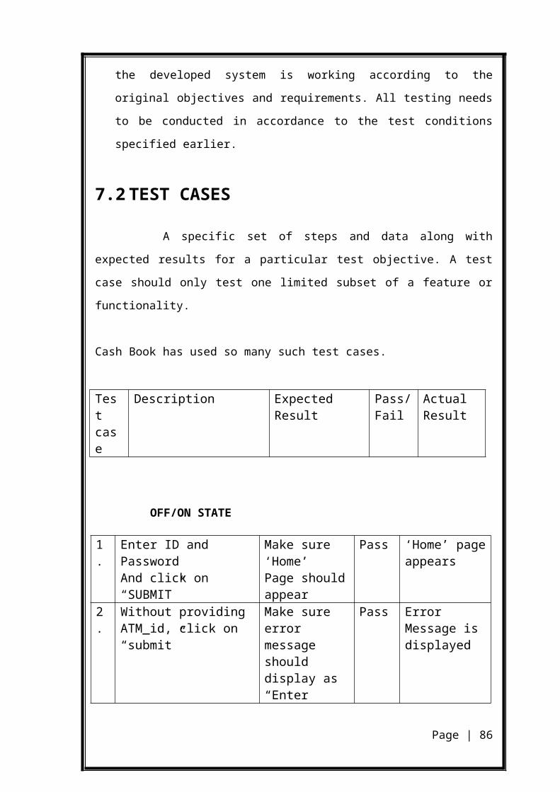
PIN CHANGE RTEPORT
Page | 86
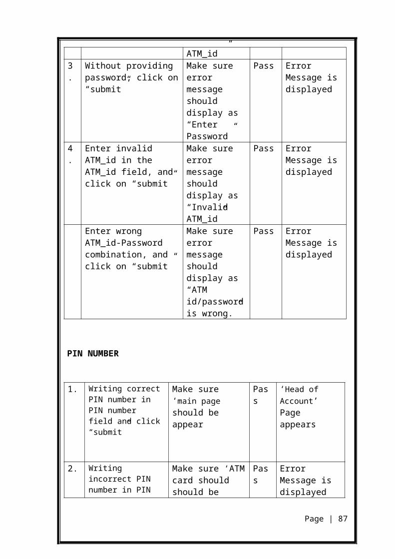
MINI STATEMENT PAGE
Page | 87
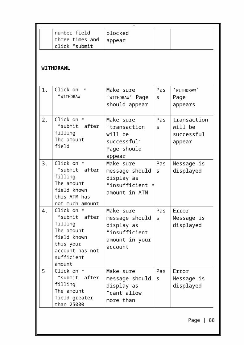
ERROR PAGE
Page | 88
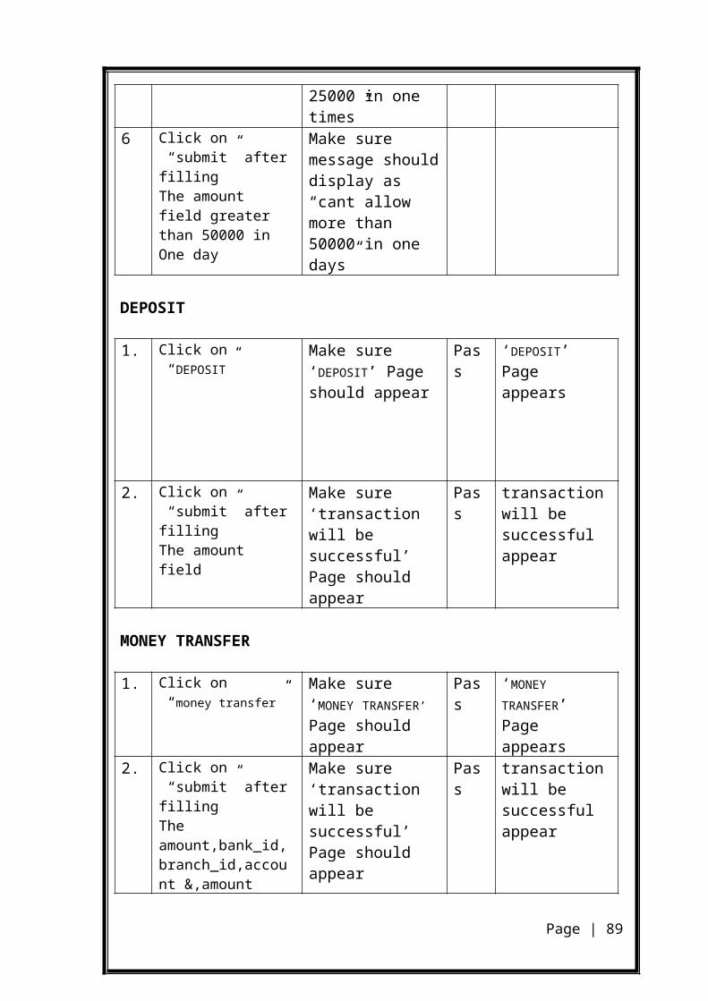
ERROR PAGE
Page | 89
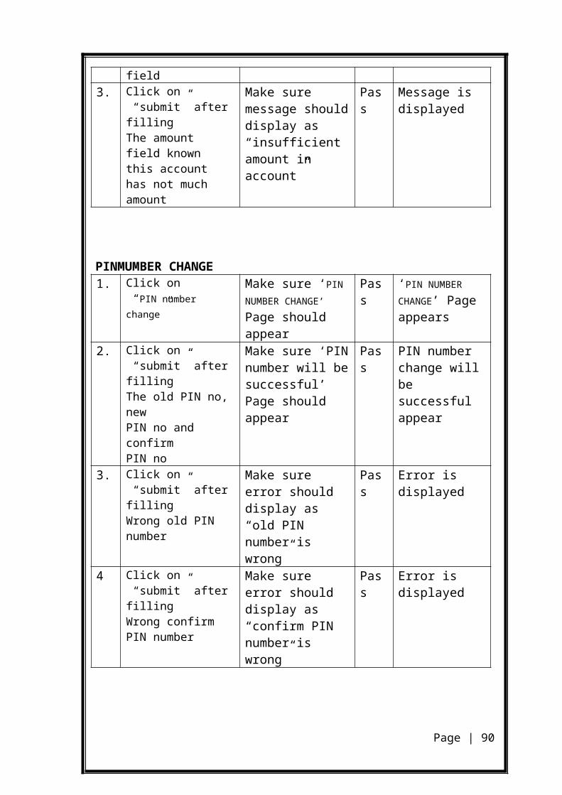
Page | 90
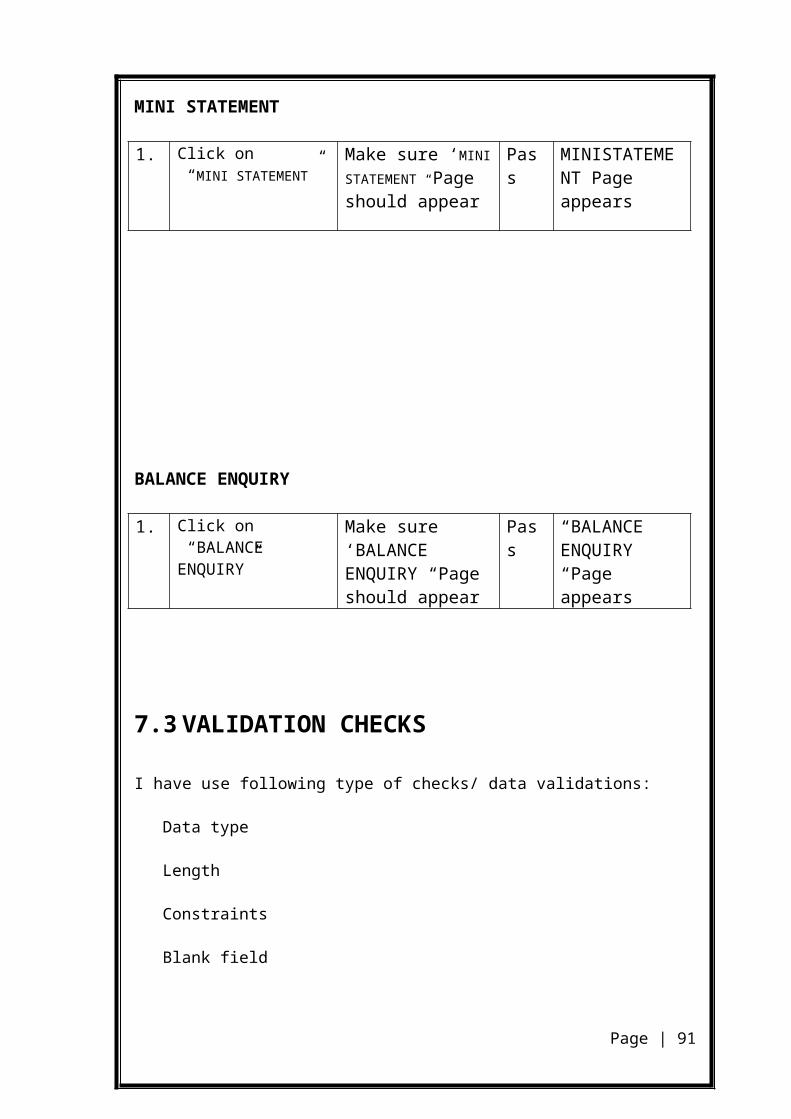
CARD BLOCKING ERROR PAGE
Page | 91
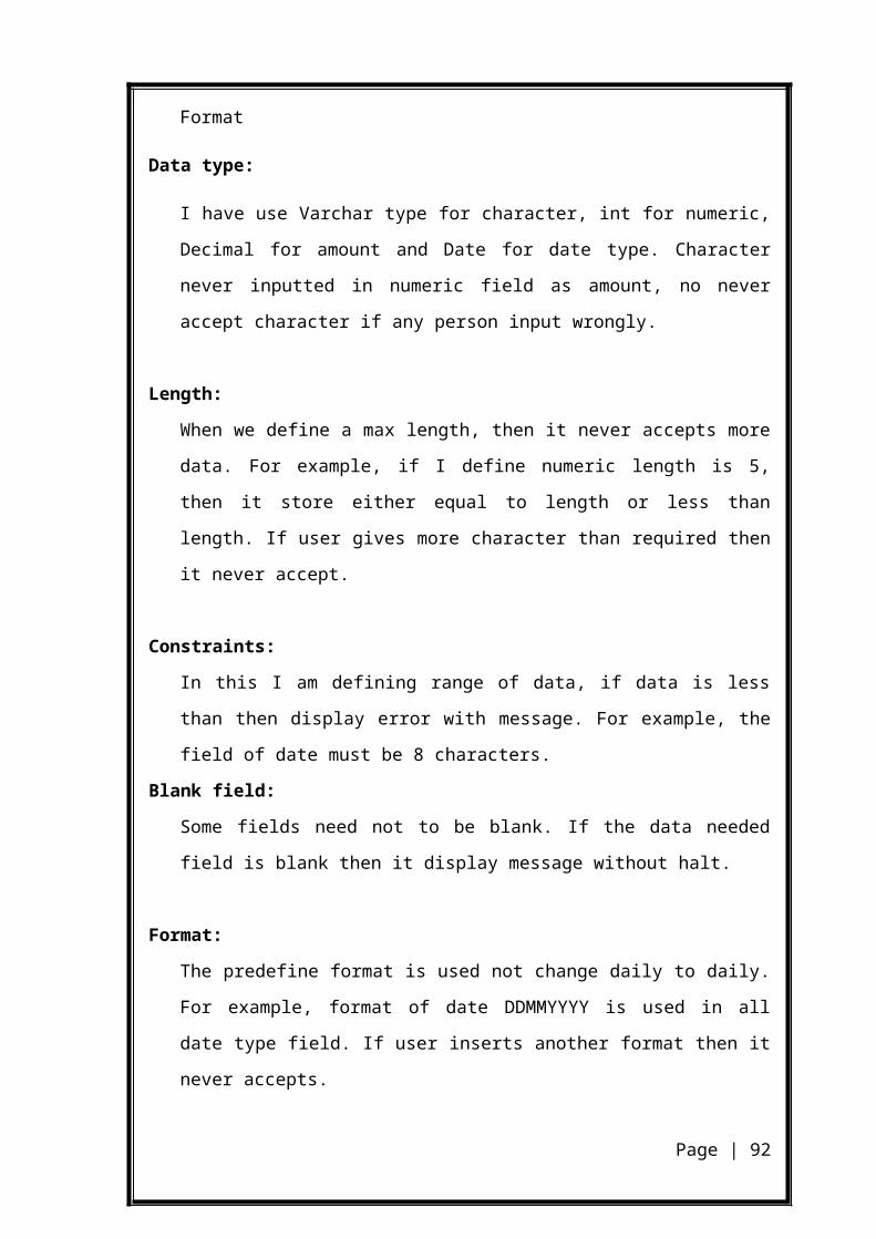
BIBLIOGRAPHY
BIBILIOGRAPHY
The Complete Reference HTML : Thoman A. Powell
The Complete Reference Java Script : Thomas A. Powell & Fritz Schneider
MySQL complete reference : vikram vaswani
Software Engineering Sixth Edition : Roger S. PressmanComplete reference of JSP : Phill Hanna E-study:
www.w3schools.com
www.wikipedia.com
Page | 92