
Atlas Copco air motors - duncanrogers.com Air motor catalogue 05.pdfAtlas Copco – air motors ......
76
Atlas Copco air motors
Transcript of Atlas Copco air motors - duncanrogers.com Air motor catalogue 05.pdfAtlas Copco – air motors ......
Atlas Copco air motors
Atlas Copco – air motors■ Leading the industry in development and innovation.
■ Offering a comprehensive range of standard air motors.
■ A premier supplier of air motors engineered to meet customerrequirements.
■ Delivering orders, on time, to customer schedules.
■ Offering a truly world-wide service.
Atlas Copco air motors – the natural choice fordesign engineers in the industry of today andtomorrow.
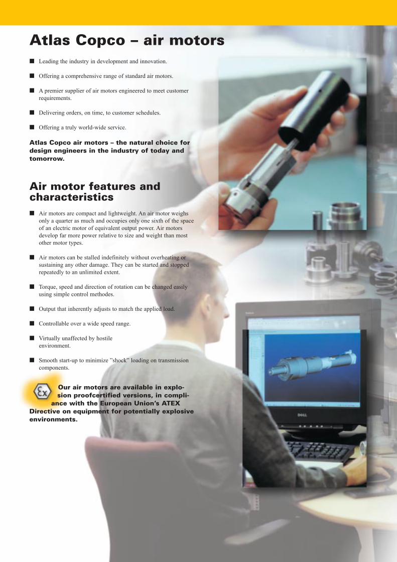
Air motor features andcharacteristics■ Air motors are compact and lightweight. An air motor weighs
only a quarter as much and occupies only one sixth of the spaceof an electric motor of equivalent output power. Air motorsdevelop far more power relative to size and weight than mostother motor types.
■ Air motors can be stalled indefinitely without overheating orsustaining any other damage. They can be started and stoppedrepeatedly to an unlimited extent.
■ Torque, speed and direction of rotation can be changed easilyusing simple control methodes.
■ Output that inherently adjusts to match the applied load.
■ Controllable over a wide speed range.
■ Virtually unaffected by hostile environment.
■ Smooth start-up to minimize �shock� loading on transmissioncomponents.
Our air motors are available in explo-sion proofcertified versions, in compli-
ance with the European Union’s ATEXDirective on equipment for potentially explosiveenvironments.
4 A T L A S C O P C O A I R M O T O R S
Log in to www.atlascopco.com24-hour access
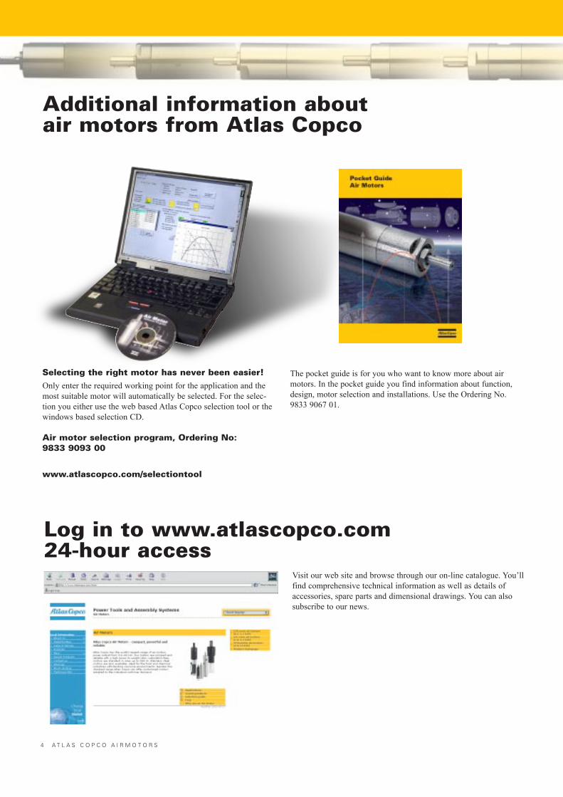
Visit our web site and browse through our on-line catalogue. You�llfind comprehensive technical information as well as details ofaccessories, spare parts and dimensional drawings. You can alsosubscribe to our news.
The pocket guide is for you who want to know more about airmotors. In the pocket guide you find information about function,design, motor selection and installations. Use the Ordering No.9833 9067 01.
Selecting the right motor has never been easier!Only enter the required working point for the application and themost suitable motor will automatically be selected. For the selec-tion you either use the web based Atlas Copco selection tool or thewindows based selection CD.
Air motor selection program, Ordering No: 9833 9093 00
www.atlascopco.com/selectiontool
Additional information aboutair motors from Atlas Copco
A T L A S C O P C O A I R M O T O R S 5
■ LZL vane motors: data, specificationand performance curves....................................................... 48LZL 05LZL 15LZL 25
■ LZL vane motor/gear unit combinations ........................... 50Helical gear units type HGWorm gear units type BSShaft loadingCalculating sprocket or gearwheel dimensionsOperating speedMountingTemperature
■ LZL air motors: with helical gear units data, specification and performance curves....................... 52LZL 05 .................................................................................... 52LZL 15 .................................................................................... 54LZL 25 .................................................................................... 56LZL 35 .....................................................................................58
■ LZL air motors: with worm gear unitsdata, specification and performance curves....................... 62LZL 05 .................................................................................... 62LZL 15 .................................................................................... 64LZL 25 .................................................................................... 66
■ Choosing your motor ........................................................... 70The Working PointAtlas Copco airmotor selection guideStarting torque and stall torqueAccelerating a load to speedShaft loadingSilencingTemperatureHostile environmentsAtlas Copco air motor selection program
■ Installing your air motor....................................................... 72AirlinesRecommended hose connectorsAir preparationLubricationControl valves for air motorsInstallation examples
■ Introducing the air motor ..................................................... 6
■ Methods of modifying motor output..................................... 7ThrottlingPressure regulation
■ Using the catalogue .................................................................. 7Motor data, specification and performance curvesUnderstanding the performanceCurvesInstallationMotor selection
■ Introduction to Atlas Copco air motors and gear units ....... 8
■ LZB vane motors introduction............................................. 10Shaft loadingMountingConnectionHose dimensions
■ LZB vane motors: data, specificationand performance curves....................................................... 14LZB 14.................................................................................... 14LZB 14R ................................................................................. 16LZB 22.................................................................................... 18LZB 22R ................................................................................. 20LZB 22LR............................................................................... 21LZB 33.................................................................................... 22LZB 34R ................................................................................. 24LZB 33LR, LZB 34R LR ....................................................... 25LZB 33 high torque ................................................................ 26LZB 33/34R with brake.......................................................... 28LZB 42.................................................................................... 30LZB 46.................................................................................... 34LZB 54.................................................................................... 38
■ Accessories for LZB motors.................................................. 42
■ LZL vane motors introduction ............................................. 44Shaft loadingMountingConnectionHose dimensions
Contents
Torque[Nm]
Speed [r/min]
Stalltorque
Minstartingtorque
Torque
Power
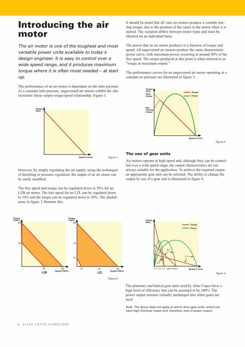
Introducing the airmotorThe air motor is one of the toughest and mostversatile power units available to today´sdesign engineer. It is easy to control over awide speed range, and it produces maximumtorque where it is often most needed – at startup.
The performance of an air motor is dependant on the inlet pressure.At a constant inlet pressure, ungoverned air motors exhibit the cha-racteristic linear output torque/speed relationship. Figure 1.
However, by simply regulating the air supply, using the techniquesof throttling or pressure regulation, the output of an air motor canbe easily modified.
The free speed and torque can be regulated down to 50% for anLZB air motor. The free speed for an LZL can be regulated downto 10% and the torque can be regulated down to 20%. The shadedareas in figure 2 illustrate this.
It should be noted that all vane air motors produce a variable star-ting torque, due to the position of the vanes in the motor when it isstarted. The variation differs between motor types and must bechecked on an individual basis.
The power that an air motor produces is a function of torque andspeed. All ungoverned air motors produce the same characteristicpower curve, with maximum power occurring at around 50% of thefree speed. The torque produced at this point is often referred to as�torque at maximum output.�
The performance curves for an ungoverned air motor operating at aconstant air pressure are illustrated in figure 3.
Figure 1
Torque[Nm]
Speed [r/min]
Torque[100%]
100
Speed [100%]50 100
50
Torque[100%]
100
Speed [100%]
10 50 100
20
50
LZB LZL
Figure 2
The use of gear units
Air motors operate at high speed and, although they can be control-led over a wide speed range, the output characteristics are notalways suitable for the application. To achieve the required outputan appropriate gear unit can be selected. The ability to change theoutput by use of a gear unit is illustrated in figure 4.
Figure 3
The planetary and helical gear units used by Atlas Copco have ahigh level of efficiency that can be assumed to be 100%. Thepower output remains virtually unchanged also when gears areused.
Note. The above does not apply to worm drive gear units, which canhave high frictional losses and, therefore, loss of power output.
Torque[Nm]
4:1
2:1
1:1
Speed [r/min]1:1, 2:1, 4:1 = gear ratios
Torque
Power
Figure 4
6 A T L A S C O P C O A I R M O T O R S
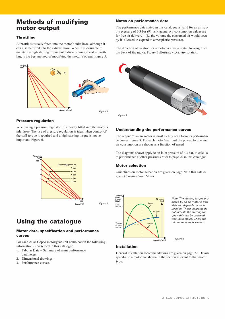
Understanding the performance curves
The output of an air motor is most clearly seen from its performan-ce curves Figure 8. For each motor/gear unit the power, torque andair consumption are shown as a function of speed.
The diagrams shown apply to an inlet pressure of 6.3 bar, to calcula-te performance at other pressures refer to page 70 in this catalogue.
Motor selection
Guidelines on motor selection are given on page 70 in this catalo-gue � Choosing Your Motor.
Methods of modifyingmotor outputThrottling
A throttle is usually fitted into the motor´s inlet hose, although itcan also be fitted into the exhaust hose. When it is desirable tomaintain a high starting torque but reduce running speed � thrott-ling is the best method of modifying the motor´s output, Figure 5.
Pressure regulation
When using a pressure regulator it is mostly fitted into the motor´sinlet hose. The use of pressure regulation is ideal when control ofthe stall torque is required and a high starting torque is not soimportant, Figure 6.
Using the catalogueMotor data, specification and performancecurves
For each Atlas Copco motor/gear unit combination the followinginformation is presented in this catalogue.1. Tabular Data � Summary of main performance
parameters.2. Dimensional drawings.3. Performance curves.
Torque[Nm]
Speed [r/min]
Notes on performance data
The performance data stated in this catalogue is valid for an air sup-ply pressure of 6.3 bar (91 psi), gauge. Air consumption values arefor free air delivery � (ie, the volume the consumed air would occu-py if allowed to expand to atmospheric pressure).
The direction of rotation for a motor is always stated looking fromthe back of the motor. Figure 7 illustrate clockwise rotation.
Figure 5
Figure 7
Torque[%]
Speed [%]
Operating pressure
7 bar
6 bar
5 bar
4 bar
3 bar
100
100
Installation
General installation recommendations are given on page 72. Detailsspecific to a motor are shown in the section relevant to that motortype.
A T L A S C O P C O A I R M O T O R S 7
Note. The starting torque pro-duced by an air motor is vari-able and depends on vaneposition. These diagrams donot indicate the starting tor-que – this can be obtainedfrom data tables, where theminimum value is shown.
Torque[Nm]Power[kW]
Maxoutput
Torqueat maxoutput
Torque
Power
Speed [r/min]
Air. cons.
Air cons.[l/s]
Figure 8
Figure 6
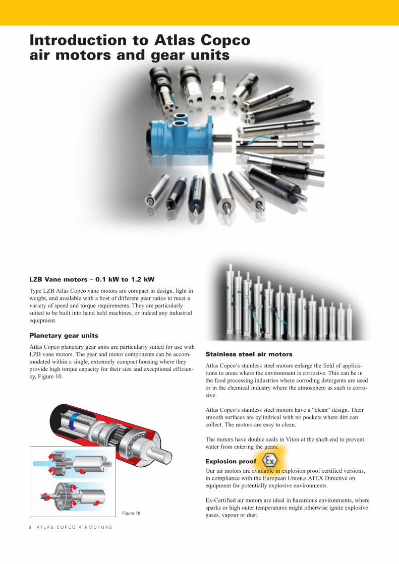
Introduction to Atlas Copcoair motors and gear units
Figure 10
8 A T L A S C O P C O A I R M O T O R S
LZB Vane motors – 0.1 kW to 1.2 kW
Type LZB Atlas Copco vane motors are compact in design, light inweight, and available with a host of different gear ratios to meet avariety of speed and torque requirements. They are particularlysuited to be built into hand held machines, or indeed any industrialequipment.
Planetary gear units
Atlas Copco planetary gear units are particularly suited for use withLZB vane motors. The gear and motor components can be accom-modated within a single, extremely compact housing where theyprovide high torque capacity for their size and exceptional efficien-cy, Figure 10.
Stainless steel air motors
Atlas Copco�s stainless steel motors enlarge the field of applica-tions to areas where the environment is corrosive. This can be inthe food processing industries where corroding detergents are usedor in the chemical industry where the atmosphere as such is corro-sive.
Atlas Copco�s stainless steel motors have a �clean� design. Theirsmooth surfaces are cylindrical with no pockets where dirt cancollect. The motors are easy to clean.
The motors have double seals in Viton at the shaft end to preventwater from entering the gears.
Explosion proofOur air motors are available in explosion proof certified versions,in compliance with the European Union.s ATEX Directive on equipment for potentially explosive environments.
Ex-Certified air motors are ideal in hazardous environments, wheresparks or high outer temperatures might otherwise ignite explosivegases, vapour or dust.
5000 r/min
500 r/min
Helical gear units
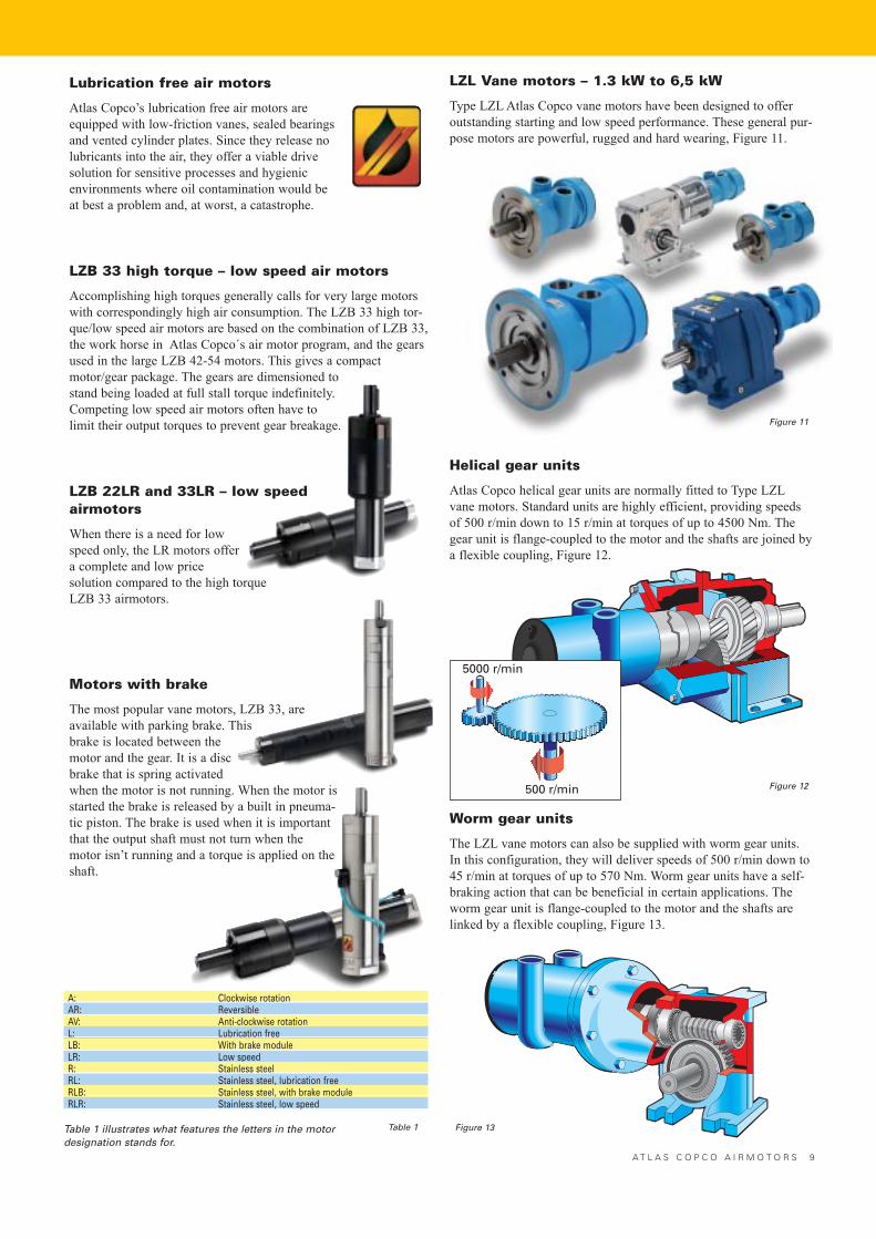
Atlas Copco helical gear units are normally fitted to Type LZLvane motors. Standard units are highly efficient, providing speedsof 500 r/min down to 15 r/min at torques of up to 4500 Nm. Thegear unit is flange-coupled to the motor and the shafts are joined bya flexible coupling, Figure 12.
LZL Vane motors – 1.3 kW to 6,5 kW
Type LZL Atlas Copco vane motors have been designed to offeroutstanding starting and low speed performance. These general pur-pose motors are powerful, rugged and hard wearing, Figure 11.
Worm gear units
The LZL vane motors can also be supplied with worm gear units.In this configuration, they will deliver speeds of 500 r/min down to45 r/min at torques of up to 570 Nm. Worm gear units have a self-braking action that can be beneficial in certain applications. Theworm gear unit is flange-coupled to the motor and the shafts arelinked by a flexible coupling, Figure 13.
Figure 11
Figure 12
Figure 13
A T L A S C O P C O A I R M O T O R S 9
Lubrication free air motors
Atlas Copco�s lubrication free air motors are equipped with low-friction vanes, sealed bearingsand vented cylinder plates. Since they release nolubricants into the air, they offer a viable drivesolution for sensitive processes and hygienic environments where oil contamination would be at best a problem and, at worst, a catastrophe.
LZB 33 high torque – low speed air motors
Accomplishing high torques generally calls for very large motorswith correspondingly high air consumption. The LZB 33 high tor-que/low speed air motors are based on the combination of LZB 33,the work horse in Atlas Copco´s air motor program, and the gearsused in the large LZB 42-54 motors. This gives a compactmotor/gear package. The gears are dimensioned tostand being loaded at full stall torque indefinitely.Competing low speed air motors often have tolimit their output torques to prevent gear breakage.
LZB 22LR and 33LR – low speedairmotors
When there is a need for lowspeed only, the LR motors offera complete and low price solution compared to the high torqueLZB 33 airmotors.
Motors with brake
The most popular vane motors, LZB 33, areavailable with parking brake. Thisbrake is located between themotor and the gear. It is a discbrake that is spring activatedwhen the motor is not running. When the motor isstarted the brake is released by a built in pneuma-tic piston. The brake is used when it is importantthat the output shaft must not turn when themotor isn�t running and a torque is applied on theshaft.
A: Clockwise rotationAR: ReversibleAV: Anti-clockwise rotationL: Lubrication freeLB: With brake moduleLR: Low speedR: Stainless steelRL: Stainless steel, lubrication freeRLB: Stainless steel, with brake moduleRLR: Stainless steel, low speed
Table 1 illustrates what features the letters in the motordesignation stands for.
Table 1
1 2 A T L A S C O P C O A I R M O T O R S
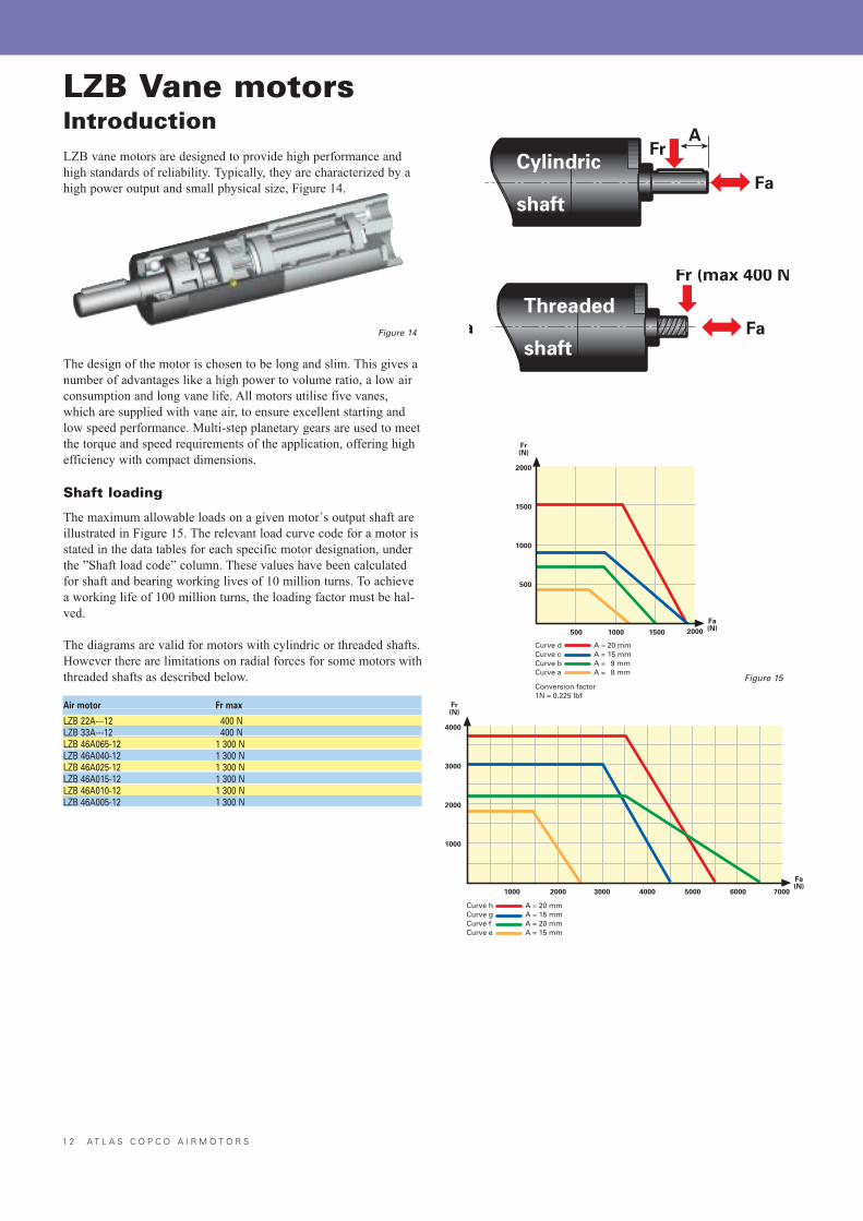
LZB Vane motorsIntroductionLZB vane motors are designed to provide high performance andhigh standards of reliability. Typically, they are characterized by ahigh power output and small physical size, Figure 14.
The design of the motor is chosen to be long and slim. This gives anumber of advantages like a high power to volume ratio, a low airconsumption and long vane life. All motors utilise five vanes,which are supplied with vane air, to ensure excellent starting andlow speed performance. Multi-step planetary gears are used to meetthe torque and speed requirements of the application, offering highefficiency with compact dimensions.
Shaft loading
The maximum allowable loads on a given motor´s output shaft areillustrated in Figure 15. The relevant load curve code for a motor isstated in the data tables for each specific motor designation, underthe �Shaft load code� column. These values have been calculatedfor shaft and bearing working lives of 10 million turns. To achievea working life of 100 million turns, the loading factor must be hal-ved.
The diagrams are valid for motors with cylindric or threaded shafts.However there are limitations on radial forces for some motors withthreaded shafts as described below.
Air motor Fr max
LZB 22A---12 400 NLZB 33A---12 400 NLZB 46A065-12 1 300 NLZB 46A040-12 1 300 NLZB 46A025-12 1 300 NLZB 46A015-12 1 300 NLZB 46A010-12 1 300 NLZB 46A005-12 1 300 N
Figure 14
Cylindric
shaft
Fr
Fa
A
Fa(N)
4000
3000
2000
1000
7000600050004000300020001000
Fr(N)
Curve hCurve gCurve fCurve e
A = 20 mmA = 15 mmA = 20 mmA = 15 mm
Fa(N)
2000
1500
1000
500
200015001000500
Fr(N)
Curve dCurve cCurve bCurve a
A = 20 mmA = 15 mmA = 9 mmA = 8 mm
Conversion factor1N = 0.225 lbf
Figure 15
Threaded
shafta Fa
Fr (max 400 N
A T L A S C O P C O A I R M O T O R S 1 3
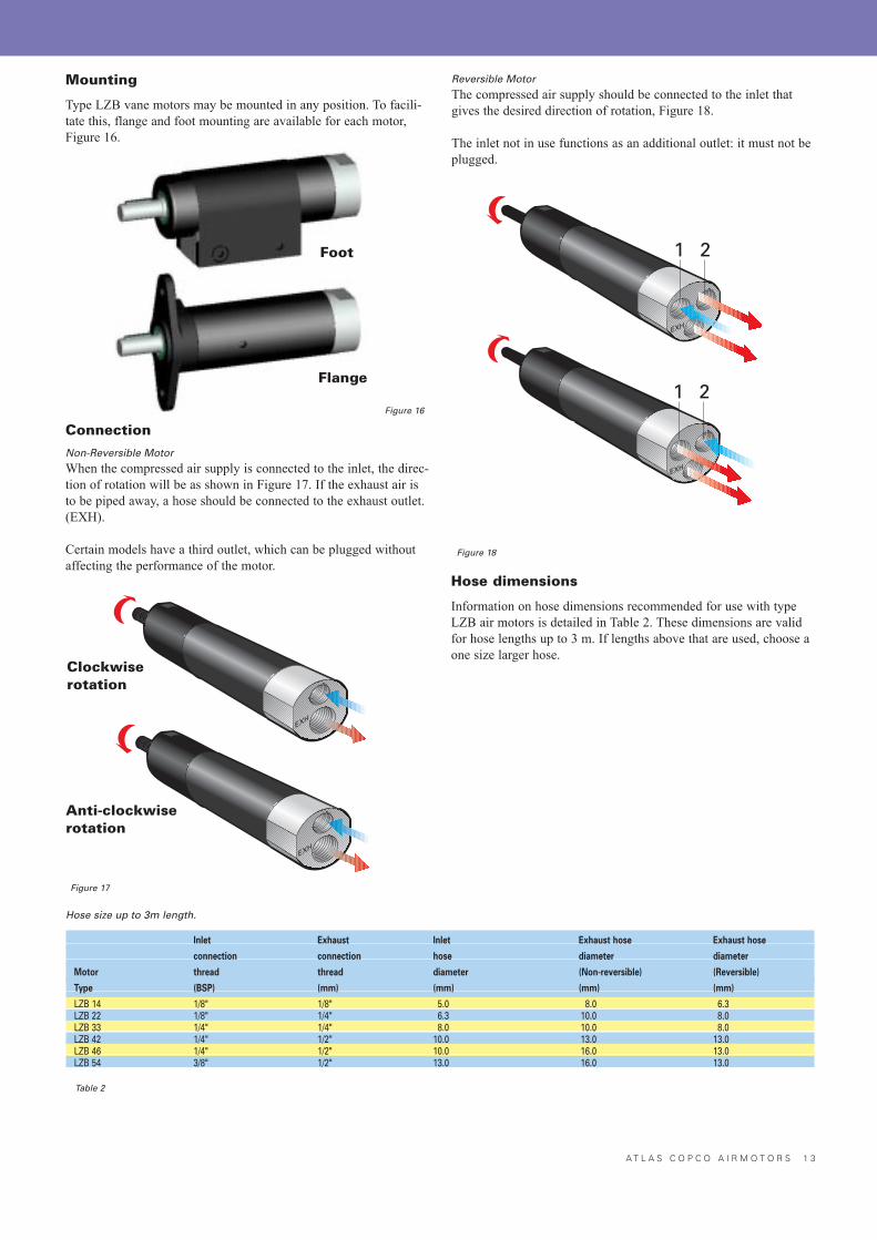
Reversible Motor
The compressed air supply should be connected to the inlet thatgives the desired direction of rotation, Figure 18.
The inlet not in use functions as an additional outlet: it must not beplugged.
Hose dimensions
Information on hose dimensions recommended for use with typeLZB air motors is detailed in Table 2. These dimensions are validfor hose lengths up to 3 m. If lengths above that are used, choose aone size larger hose.
Figure 17
Figure 18
Hose size up to 3m length.
Inlet Exhaust Inlet Exhaust hose Exhaust hose
connection connection hose diameter diameter
Motor thread thread diameter (Non-reversible) (Reversible)
Type (BSP) (mm) (mm) (mm) (mm)
LZB 14 1/8" 1/8" 5.0 8.0 6.3LZB 22 1/8" 1/4" 6.3 10.0 8.0LZB 33 1/4" 1/4" 8.0 10.0 8.0LZB 42 1/4" 1/2" 10.0 13.0 13.0LZB 46 1/4" 1/2" 10.0 16.0 13.0LZB 54 3/8" 1/2" 13.0 16.0 13.0
Table 2
Mounting
Type LZB vane motors may be mounted in any position. To facili-tate this, flange and foot mounting are available for each motor,Figure 16.
ConnectionNon-Reversible Motor
When the compressed air supply is connected to the inlet, the direc-tion of rotation will be as shown in Figure 17. If the exhaust air isto be piped away, a hose should be connected to the exhaust outlet.(EXH).
Certain models have a third outlet, which can be plugged withoutaffecting the performance of the motor.
Figure 16
1 2
1 2Foot
Flange
Clockwiserotation
Anti-clockwiserotation
1 4 A T L A S C O P C O A I R M O T O R S
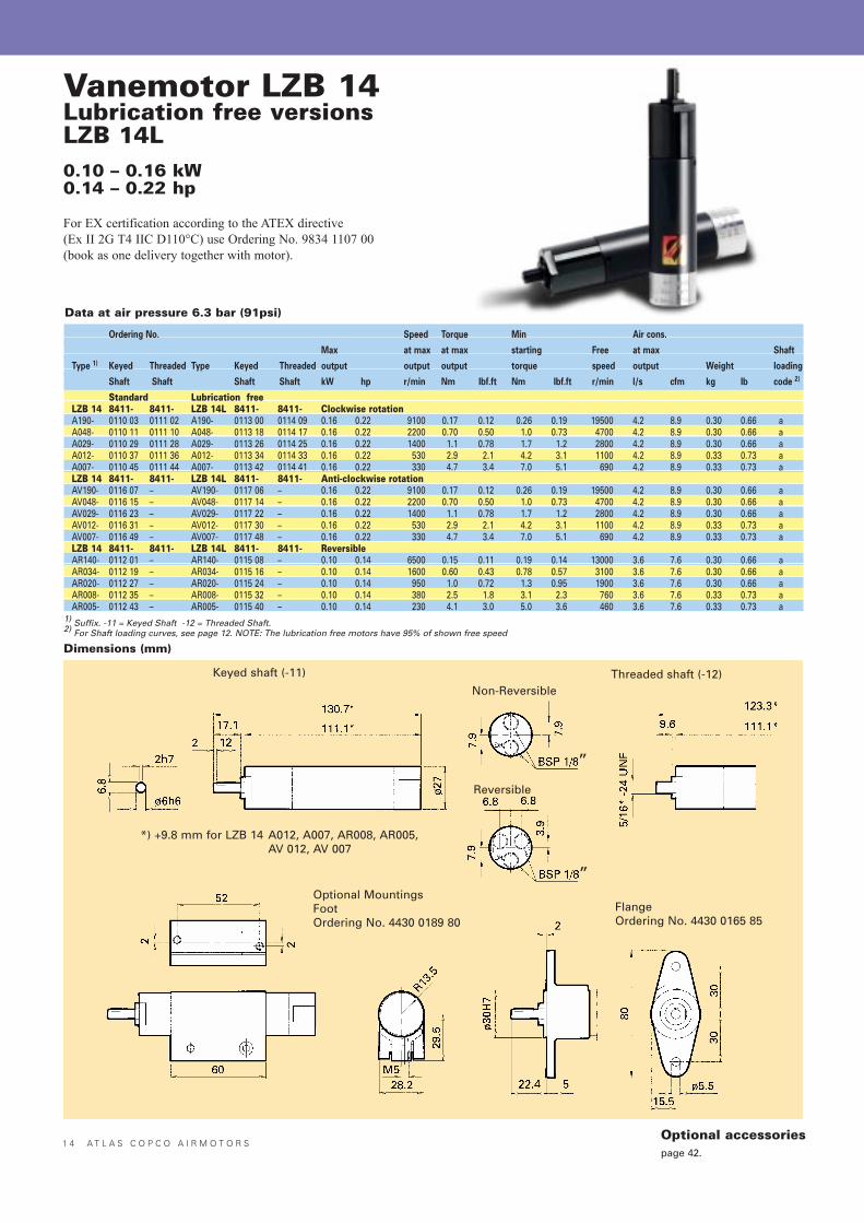
Vanemotor LZB 14Lubrication free versionsLZB 14L0.10 – 0.16 kW0.14 – 0.22 hp
For EX certification according to the ATEX directive (Ex II 2G T4 IIC D110°C) use Ordering No. 9834 1107 00(book as one delivery together with motor).
Keyed shaft (-11) Threaded shaft (-12)Non-Reversible
Reversible
FlangeOrdering No. 4430 0165 85
Optional MountingsFootOrdering No. 4430 0189 80
*) +9.8 mm for LZB 14 A012, A007, AR008, AR005, AV 012, AV 007
Ordering No. Speed Torque Min Air cons.
Max at max at max starting Free at max Shaft
Type 1) Keyed Threaded Type Keyed Threaded output output output torque speed output Weight loading
Shaft Shaft Shaft Shaft kW hp r/min Nm Ibf.ft Nm Ibf.ft r/min l/s cfm kg Ib code 2)
Standard Lubrication freeLZB 14 8411- 8411- LZB 14L 8411- 8411- Clockwise rotationA190- 0110 03 0111 02 A190- 0113 00 0114 09 0.16 0.22 9100 0.17 0.12 0.26 0.19 19500 4.2 8.9 0.30 0.66 aA048- 0110 11 0111 10 A048- 0113 18 0114 17 0.16 0.22 2200 0.70 0.50 1.0 0.73 4700 4.2 8.9 0.30 0.66 aA029- 0110 29 0111 28 A029- 0113 26 0114 25 0.16 0.22 1400 1.1 0.78 1.7 1.2 2800 4.2 8.9 0.30 0.66 aA012- 0110 37 0111 36 A012- 0113 34 0114 33 0.16 0.22 530 2.9 2.1 4.2 3.1 1100 4.2 8.9 0.33 0.73 aA007- 0110 45 0111 44 A007- 0113 42 0114 41 0.16 0.22 330 4.7 3.4 7.0 5.1 690 4.2 8.9 0.33 0.73 aLZB 14 8411- 8411- LZB 14L 8411- 8411- Anti-clockwise rotationAV190- 0116 07 – AV190- 0117 06 – 0.16 0.22 9100 0.17 0.12 0.26 0.19 19500 4.2 8.9 0.30 0.66 aAV048- 0116 15 – AV048- 0117 14 – 0.16 0.22 2200 0.70 0.50 1.0 0.73 4700 4.2 8.9 0.30 0.66 aAV029- 0116 23 – AV029- 0117 22 – 0.16 0.22 1400 1.1 0.78 1.7 1.2 2800 4.2 8.9 0.30 0.66 aAV012- 0116 31 – AV012- 0117 30 – 0.16 0.22 530 2.9 2.1 4.2 3.1 1100 4.2 8.9 0.33 0.73 aAV007- 0116 49 – AV007- 0117 48 – 0.16 0.22 330 4.7 3.4 7.0 5.1 690 4.2 8.9 0.33 0.73 aLZB 14 8411- 8411- LZB 14L 8411- 8411- ReversibleAR140- 0112 01 – AR140- 0115 08 – 0.10 0.14 6500 0.15 0.11 0.19 0.14 13000 3.6 7.6 0.30 0.66 aAR034- 0112 19 – AR034- 0115 16 – 0.10 0.14 1600 0.60 0.43 0.78 0.57 3100 3.6 7.6 0.30 0.66 aAR020- 0112 27 – AR020- 0115 24 – 0.10 0.14 950 1.0 0.72 1.3 0.95 1900 3.6 7.6 0.30 0.66 aAR008- 0112 35 – AR008- 0115 32 – 0.10 0.14 380 2.5 1.8 3.1 2.3 760 3.6 7.6 0.33 0.73 aAR005- 0112 43 – AR005- 0115 40 – 0.10 0.14 230 4.1 3.0 5.0 3.6 460 3.6 7.6 0.33 0.73 a
1) Suffix. -11 = Keyed Shaft -12 = Threaded Shaft.2) For Shaft loading curves, see page 12. NOTE: The lubrication free motors have 95% of shown free speed
Dimensions (mm)
Data at air pressure 6.3 bar (91psi)
”
”
Optional accessoriespage 42.
A T L A S C O P C O A I R M O T O R S 1 5
Nm LZB 14 A190 l/s
r/min
kW0.180.160.140.120.100.080.060.040.02
0.350.300.250.200.150.100.05
54321
4000 8000 2000012000 16000
Nm LZB 14 A048 l/s
r/min
kW0.180.160.140.120.100.080.060.040.02
1.41.21.00.80.60.40.2
54321
1000 2000 50003000 4000
Nm LZB 14 A029 l/s
r/min
kW0.180.160.140.120.100.080.060.040.02
2.42.01.61.20.80.4
54321
500 1000 30001500 2000 2500
Nm LZB 14 A012 l/s
r/min
kW0.180.160.140.120.100.080.060.040.02
654321
54321
300 600 1200900
Nm LZB 14 A007 l/s
r/min
kW0.180.160.140.120.100.080.060.040.02
987654321
54321
100 300 700500200 400 600
Nm LZB 14 AR140 l/s
r/min
kW0.10
0.08
0.06
0.04
0.02
0.3
0.2
0.1
5
4
3
2
1
3000 9000 150006000 12000
Nm LZB 14 AR034 l/s
r/min
kW0.10
0.08
0.06
0.04
0.02
1.2
0.8
0.4
5
4
3
2
1
500 1500 35001000 2000 2500 3000
Nm LZB 14 AR008 l/s
r/min
kW0.10
0.08
0.06
0.04
0.02
5
4
3
2
1
5
4
3
2
1
100 300 800200 400 500 600 700
Nm LZB 14 AR020 l/s
r/min
kW0.10
0.08
0.06
0.04
0.02
2.0
1.6
1.2
0.8
0.4
5
4
3
2
1
400 1200 2000800 1600
Nm LZB 14 AR005 l/s
r/min
kW0.10
0.08
0.06
0.04
0.02
8
6
4
2
5
4
3
2
1
100 300 500200 400
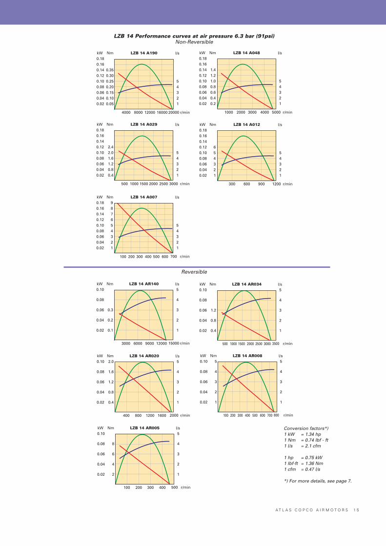
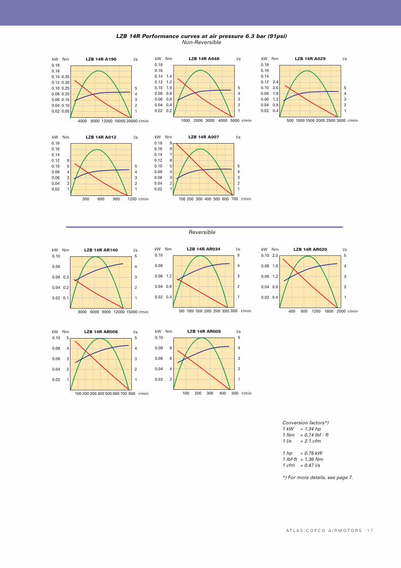
LZB 14 Performance curves at air pressure 6.3 bar (91psi)Non-Reversible
Reversible
Conversion factors*)1 kW = 1.34 hp1 Nm = 0.74 Ibf - ft1 l/s = 2.1 cfm
1 hp = 0.75 kW1 Ibf-ft = 1.36 Nm1 cfm = 0.47 l/s
*) For more details, see page 7.
1 6 A T L A S C O P C O A I R M O T O R S
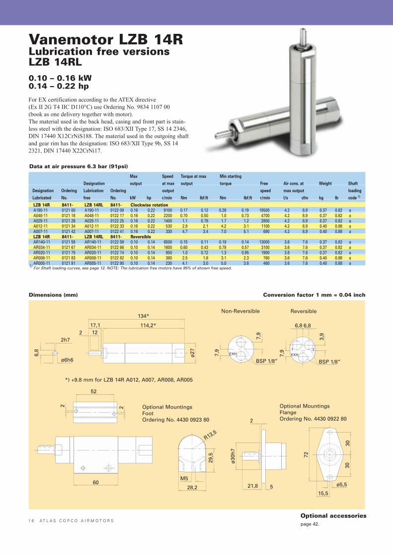
Vanemotor LZB 14RLubrication free versionsLZB 14RL0.10 – 0.16 kW0.14 – 0.22 hp
7,9
6,8
BSP 1/8”
7,9
EXH
6,8
1 2
7,9
EXH
3,9
BSP 1/8”
134*
ø27
114,2*17,1122
2h7
ø6h6
6,8
M5
28,2
R13,5
29,5
ø30
h7
21,8
2
5
72
3030
ø5,5
15,5
60
22
52
Non-Reversible Reversible
Optional MountingsFlangeOrdering No. 4430 0922 80
Optional MountingsFootOrdering No. 4430 0923 80
*) +9.8 mm for LZB 14R A012, A007, AR008, AR005
Max Speed Torque at max Min starting
Designation output at max output torque Free Air cons. at Weight Shaft
Designation Ordering Lubrication Ordering output speed max output loading
Lubricated No. free No. kW hp r/min Nm Ibf.ft Nm Ibf.ft r/min l/s cfm kg Ib code 1)
LZB 14R 8411- LZB 14RL 8411- Clockwise rotationA190-11 0121 00 A190-11 0122 09 0.16 0.22 9100 0.17 0.12 0.26 0.19 19500 4.2 8.9 0.37 0.82 aA048-11 0121 18 A048-11 0122 17 0.16 0.22 2200 0.70 0.50 1.0 0.73 4700 4.2 8.9 0.37 0.82 aA029-11 0121 26 A029-11 0122 25 0.16 0.22 1400 1.1 0.78 1.7 1.2 2800 4.2 8.9 0.37 0.82 aA012-11 0121 34 A012-11 0122 33 0.16 0.22 530 2.9 2.1 4.2 3.1 1100 4.2 8.9 0.40 0.88 aA007-11 0121 42 A007-11 0122 41 0.16 0.22 330 4.7 3.4 7.0 5.1 690 4.2 8.9 0.40 0.88 aLZB 14R 8411- LZB 14RL 8411- ReversibleAR140-11 0121 59 AR140-11 0122 58 0.10 0.14 6500 0.15 0.11 0.19 0.14 13000 3.6 7.6 0.37 0.82 aAR034-11 0121 67 AR034-11 0122 66 0.10 0.14 1600 0.60 0.43 0.78 0.57 3100 3.6 7.6 0.37 0.82 aAR020-11 0121 75 AR020-11 0122 74 0.10 0.14 950 1.0 0.72 1.3 0.95 1900 3.6 7.6 0.37 0.82 aAR008-11 0121 83 AR008-11 0122 82 0.10 0.14 380 2.5 1.8 3.1 2.3 760 3.6 7.6 0.40 0.88 aAR005-11 0121 91 AR005-11 0122 90 0.10 0.14 230 4.1 3.0 5.0 3.6 460 3.6 7.6 0.40 0.88 a
1) For Shaft loading curves, see page 12. NOTE: The lubrication free motors have 95% of shown free speed.
Dimensions (mm)
Data at air pressure 6.3 bar (91psi)
Conversion factor 1 mm = 0.04 inch
For EX certification according to the ATEX directive (Ex II 2G T4 IIC D110°C) use Ordering No. 9834 1107 00(book as one delivery together with motor).The material used in the back head, casing and front part is stain-less steel with the designation: ISO 683/XII Type 17, SS 14 2346,DIN 17440 X12CrNiS188. The material used in the outgoing shaftand gear rim has the designation: ISO 683/XII Type 9b, SS 142321, DIN 17440 X22CrNi17.
Optional accessoriespage 42.
A T L A S C O P C O A I R M O T O R S 1 7
Nm LZB 14R A190 l/s
r/min
kW0.180.160.140.120.100.080.060.040.02
0.350.300.250.200.150.100.05
54321
4000 8000 2000012000 16000
Nm LZB 14R A048 l/s
r/min
kW0.180.160.140.120.100.080.060.040.02
1.41.21.00.80.60.40.2
54321
1000 2000 50003000 4000
Nm LZB 14R A029 l/s
r/min
kW0.180.160.140.120.100.080.060.040.02
2.42.01.61.20.80.4
54321
500 1000 30001500 2000 2500
Nm LZB 14R A012 l/s
r/min
kW0.180.160.140.120.100.080.060.040.02
654321
54321
300 1200600 900
Nm LZB 14R A007 l/s
r/min
kW0.180.160.140.120.100.080.060.040.02
987654321
54321
100 700200 300 400 500 600
Nm LZB 14R AR020 l/s
r/min
kW0.10
0.08
0.06
0.04
0.02
2.0
1.6
1.2
0.8
0.4
5
4
3
2
1
400 2000800 1200 1600
Nm LZB 14R AR140 l/s
r/min
kW0.10
0.08
0.06
0.04
0.02
0.3
0.2
0.1
5
4
3
2
1
3000 150006000 9000 12000
Nm LZB 14R AR008 l/s
r/min
kW0.10
0.08
0.06
0.04
0.02
5
4
3
2
1
5
4
3
2
1
100 800200 300 400 500 600 700
Nm LZB 14R AR034 l/s
r/min
kW0.10
0.08
0.06
0.04
0.02
1.2
0.8
0.4
5
4
3
2
1
500 35001000 1500 2000 2500 3000
Nm LZB 14R AR005 l/s
r/min
kW0.10
0.08
0.06
0.04
0.02
8
6
4
2
5
4
3
2
1
100 500200 300 400
LZB 14R Performance curves at air pressure 6.3 bar (91psi)Non-Reversible
Reversible
Conversion factors*)1 kW = 1.34 hp1 Nm = 0.74 Ibf - ft1 l/s = 2.1 cfm
1 hp = 0.75 kW1 Ibf-ft = 1.36 Nm1 cfm = 0.47 l/s
*) For more details, see page 7.
1 8 A T L A S C O P C O A I R M O T O R S
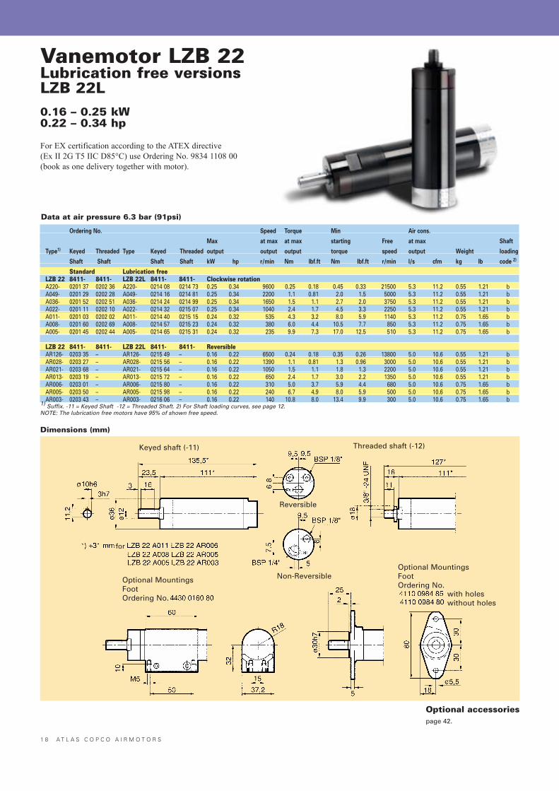
Vanemotor LZB 22Lubrication free versionsLZB 22L0.16 – 0.25 kW0.22 – 0.34 hp
For EX certification according to the ATEX directive (Ex II 2G T5 IIC D85°C) use Ordering No. 9834 1108 00(book as one delivery together with motor).
Ordering No. Speed Torque Min Air cons.
Max at max at max starting Free at max Shaft
Type1) Keyed Threaded Type Keyed Threaded output output output torque speed output Weight loading
Shaft Shaft Shaft Shaft kW hp r/min Nm Ibf.ft Nm Ibf.ft r/min l/s cfm kg Ib code 2)
Standard Lubrication freeLZB 22 8411- 8411- LZB 22L 8411- 8411- Clockwise rotationA220- 0201 37 0202 36 A220- 0214 08 0214 73 0.25 0.34 9600 0.25 0.18 0.45 0.33 21500 5.3 11.2 0.55 1.21 bA049- 0201 29 0202 28 A049- 0214 16 0214 81 0.25 0.34 2200 1.1 0.81 2.0 1.5 5000 5.3 11.2 0.55 1.21 bA036- 0201 52 0202 51 A036- 0214 24 0214 99 0.25 0.34 1650 1.5 1.1 2.7 2.0 3750 5.3 11.2 0.55 1.21 bA022- 0201 11 0202 10 A022- 0214 32 0215 07 0.25 0.34 1040 2.4 1.7 4.5 3.3 2250 5.3 11.2 0.55 1.21 bA011- 0201 03 0202 02 A011- 0214 40 0215 15 0.24 0.32 535 4.3 3.2 8.0 5.9 1140 5.3 11.2 0.75 1.65 bA008- 0201 60 0202 69 A008- 0214 57 0215 23 0.24 0.32 380 6.0 4.4 10.5 7.7 850 5.3 11.2 0.75 1.65 bA005- 0201 45 0202 44 A005- 0214 65 0215 31 0.24 0.32 235 9.9 7.3 17.0 12.5 510 5.3 11.2 0.75 1.65 b
LZB 22 8411- 8411- LZB 22L 8411- 8411- ReversibleAR126- 0203 35 – AR126- 0215 49 – 0.16 0.22 6500 0.24 0.18 0.35 0.26 13800 5.0 10.6 0.55 1.21 bAR028- 0203 27 – AR028- 0215 56 – 0.16 0.22 1390 1.1 0.81 1.3 0.96 3000 5.0 10.6 0.55 1.21 bAR021- 0203 68 – AR021- 0215 64 – 0.16 0.22 1050 1.5 1.1 1.8 1.3 2200 5.0 10.6 0.55 1.21 bAR013- 0203 19 – AR013- 0215 72 – 0.16 0.22 650 2.4 1.7 3.0 2.2 1350 5.0 10.6 0.55 1.21 bAR006- 0203 01 – AR006- 0215 80 – 0.16 0.22 310 5.0 3.7 5.9 4.4 680 5.0 10.6 0.75 1.65 bAR005- 0203 50 – AR005- 0215 98 – 0.16 0.22 240 6.7 4.9 8.0 5.9 500 5.0 10.6 0.75 1.65 bAR003- 0203 43 – AR003- 0216 06 – 0.16 0.22 140 10.8 8.0 13.4 9.9 300 5.0 10.6 0.75 1.65 b
1) Suffix. -11 = Keyed Shaft -12 = Threaded Shaft. 2) For Shaft loading curves, see page 12.NOTE: The lubrication free motors have 95% of shown free speed.
Keyed shaft (-11) Threaded shaft (-12)
Non-Reversible
with holeswithout holes
Optional MountingsFootOrdering No.
Reversible
Optional MountingsFootOrdering No.
for
Dimensions (mm)
Data at air pressure 6.3 bar (91psi)
Optional accessoriespage 42.
A T L A S C O P C O A I R M O T O R S 1 9
Nm LZB 22 A220 l/s
r/min
kW0.30
0.25
0.20
0.15
0.10
0.05
0.6
0.5
0.4
0.3
0.2
0.1
6
4
2
2000010000
Nm LZB 22 A049 l/s
r/min
kW
0.25
0.20
0.15
0.10
0.05
2.5
2.0
1.5
1.0
0.5
6
4
2
40002000 6000
Nm LZB 22 A036 l/s
r/min
kW0.30
0.25
0.20
0.15
0.10
0.05
3.0
2.5
2.0
1.5
1.0
0.5
6
4
2
20001000 3000 4000
Nm LZB 22 A022 l/s
r/min
kW
0.25
0.20
0.15
0.10
0.05
5
4
3
2
1
6
4
2
1000500 1500 2000 2500
Nm LZB 22 A011 l/s
r/min
kW
0.25
0.20
0.15
0.10
0.05
10
8
6
4
2
6
4
2
400200 600 800 12001000
Nm LZB 22 A008 l/s
r/min
kW
0.25
0.20
0.15
0.10
0.05
12
10
8
6
4
2
6
4
2
400200 600 800 1000
Nm LZB 22 A005 l/s
r/min
kW
0.25
0.20
0.15
0.10
0.05
20
16
12
8
4
6
4
2
200100 300 400 600500
Nm LZB 22 AR126 l/s
r/min
kW0.18
0.15
0.12
0.09
0.06
0.03
0.5
0.4
0.3
0.2
0.1
6
4
2
4000 8000 12000
Nm LZB 22 AR028 l/s
r/min
kW0.18
0.15
0.12
0.09
0.06
0.03
2.0
1.6
1.2
0.8
0.4
6
4
2
1000 2000 3000
Nm LZB 22 AR021 l/s
r/min
kW0.18
0.15
0.12
0.09
0.06
0.03
2.4
2.0
1.6
1.2
0.8
0.4
6
4
2
500 1000 1500 2000 2500
Nm LZB 22 AR013 l/s
r/min
kW0.18
0.15
0.12
0.09
0.06
0.03
4
3
2
1
6
4
2
300 600 900 1200 1500
Nm LZB 22 AR006 l/s
r/min
kW0.18
0.15
0.12
0.09
0.06
0.03
10
8
6
4
2
6
4
2
200 400 600 800
Nm LZB 22 AR005 l/s
r/min
kW0.18
0.15
0.12
0.09
0.06
0.03
12
10
8
6
4
2
6
4
2
200 400 600
Nm LZB 22 AR003 l/s
r/min
kW0.18
0.15
0.12
0.09
0.06
0.03
20
16
12
8
4
6
4
2
100 200 300
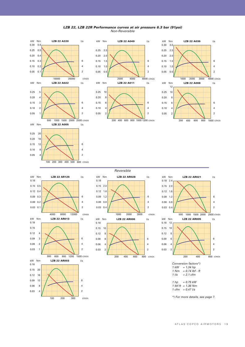
LZB 22, LZB 22R Performance curves at air pressure 6.3 bar (91psi)Non-Reversible
Reversible
Conversion factors*)1 kW = 1.34 hp1 Nm = 0.74 Ibf - ft1 l/s = 2.1 cfm
1 hp = 0.75 kW1 Ibf-ft = 1.36 Nm1 cfm = 0.47 l/s
*) For more details, see page 7.
2 0 A T L A S C O P C O A I R M O T O R S
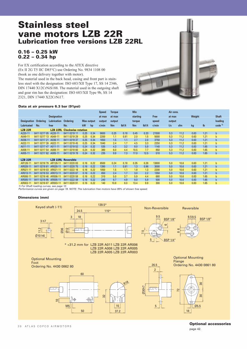
Stainless steelvane motors LZB 22RLubrication free versions LZB 22RL0.16 – 0.25 kW0.22 – 0.34 hp
Speed Torque Min Air cons.
Designation at max at max starting Free at max Weight Shaft
Designation Ordering Lubrication Ordering Max output output output torque speed output loading
Lubricated No. free No. kW hp r/min Nm Ibf.ft Nm Ibf.ft r/min l/s cfm kg Ib code 1)
LZB 22R LZB 22RL Clockwise rotationA220-11 8411 0217 05 A220-11 8411 0219 11 0.25 0.34 9600 0.25 0.18 0.45 0.33 21500 5.3 11.2 0.63 1.21 bA049-11 8411 0217 13 A049-11 8411 0219 29 0.25 0.34 2200 1.1 0.81 2.0 1.5 5000 5.3 11.2 0.63 1.21 bA036-11 8411 0217 21 A036-11 8411 0219 37 0.25 0.34 1650 1.5 1.1 2.7 2.0 3750 5.3 11.2 0.63 1.21 bA022-11 8411 0217 39 A022-11 8411 0219 45 0.25 0.34 1040 2.4 1.7 4.5 3.3 2250 5.3 11.2 0.63 1.21 bA011-11 8411 0217 47 A011-11 8411 0219 52 0.24 0.32 535 4.3 3.2 8.0 5.9 1140 5.3 11.2 0.83 1.65 bA008-11 8411 0217 54 A008-11 8411 0219 60 0.24 0.32 380 6.0 4.4 10.5 7.7 850 5.3 11.2 0.83 1.65 bA005-11 8411 0217 62 A005-11 8411 0219 78 0.24 0.32 235 9.9 7.3 17.0 12.5 510 5.3 11.2 0.83 1.65 b
LZB 22R LZB 22RL ReversibleAR126-11 8411 0218 79 AR126-11 8411 0220 83 0.16 0.22 6500 0.24 0.18 0.35 0.26 13800 5.0 10.6 0.63 1.21 bAR028-11 8411 0218 61 AR028-11 8411 0220 75 0.16 0.22 1390 1.1 0.81 1.3 0.96 3000 5.0 10.6 0.63 1.21 bAR021-11 8411 0219 03 AR021-11 8411 0222 16 0.16 0.22 1050 1.5 1.1 1.8 1.3 2200 5.0 10.6 0.63 1.21 bAR013-11 8411 0218 53 AR013-11 8411 0220 67 0.16 0.22 650 2.4 1.7 3.0 2.2 1350 5.0 10.6 0.63 1.21 bAR006-11 8411 0218 46 AR006-11 8411 0220 59 0.16 0.22 310 5.0 3.7 5.9 4.4 680 5.0 10.6 0.83 1.65 bAR005-11 8411 0218 95 AR005-11 8411 0222 08 0.16 0.22 240 6.7 4.9 8.0 5.9 500 5.0 10.6 0.83 1.65 bAR003-11 8411 0218 87 AR003-11 8411 0220 91 0.16 0.22 140 10.8 8.0 13.4 9.9 300 5.0 10.6 0.83 1.65 b
1) For Shaft loading curves, see page 12.Performance curves are given on page 19. NOTE: The lubrication free motors have 95% of shown free speed.
Data at air pressure 6.3 bar (91psi)
For EX certification according to the ATEX directive (Ex II 2G T5 IIC D85°C) use Ordering No. 9834 1108 00(book as one delivery together with motor).The material used in the back head, casing and front part is stain-less steel with the designation: ISO 683/XII Type 17, SS 14 2346,DIN 17440 X12CrNiS188. The material used in the outgoing shaftand gear rim has the designation: ISO 683/XII Type 9b, SS 142321, DIN 17440 X22CrNi17.
Dimensions (mm)
Keyed shaft (-11)
* +31.2 mm for LZB 22R A011 LZB 22R AR006LZB 22R A008 LZB 22R AR005LZB 22R A005 LZB 22R AR003
Non-Reversible Reversible
Optional MountingFlangeOrdering No. 4430 0861 80
Optional MountingFootOrdering No. 4430 0862 80
Optional accessoriespage 42.
A T L A S C O P C O A I R M O T O R S 2 1
Free Air Shaft
Designation Ordering Designation Ordering speed consumtion Weight loading
Lubricated No. Lubrication free No. r/min l/s cfm kg lb code 1)
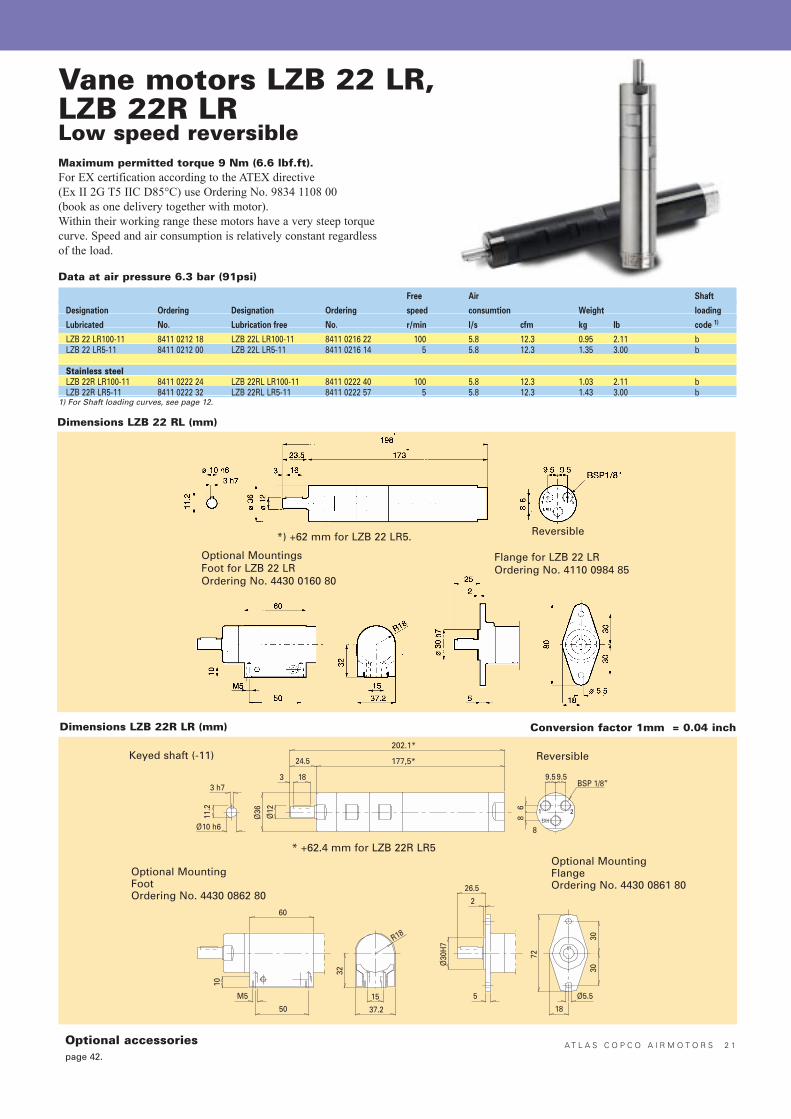
LZB 22 LR100-11 8411 0212 18 LZB 22L LR100-11 8411 0216 22 100 5.8 12.3 0.95 2.11 bLZB 22 LR5-11 8411 0212 00 LZB 22L LR5-11 8411 0216 14 5 5.8 12.3 1.35 3.00 b
Stainless steelLZB 22R LR100-11 8411 0222 24 LZB 22RL LR100-11 8411 0222 40 100 5.8 12.3 1.03 2.11 bLZB 22R LR5-11 8411 0222 32 LZB 22RL LR5-11 8411 0222 57 5 5.8 12.3 1.43 3.00 b
1) For Shaft loading curves, see page 12.
Vane motors LZB 22 LR,LZB 22R LRLow speed reversibleMaximum permitted torque 9 Nm (6.6 lbf.ft).For EX certification according to the ATEX directive (Ex II 2G T5 IIC D85°C) use Ordering No. 9834 1108 00(book as one delivery together with motor).Within their working range these motors have a very steep torquecurve. Speed and air consumption is relatively constant regardlessof the load.
Data at air pressure 6.3 bar (91psi)
Dimensions LZB 22 RL (mm)
Optional MountingsFoot for LZB 22 LROrdering No. 4430 0160 80
Reversible
Flange for LZB 22 LROrdering No. 4110 0984 85
Dimensions LZB 22R LR (mm) Conversion factor 1mm = 0.04 inch
Keyed shaft (-11)
* +62.4 mm for LZB 22R LR5
Reversible
Optional MountingFlangeOrdering No. 4430 0861 80
Optional MountingFootOrdering No. 4430 0862 80
*) +62 mm for LZB 22 LR5.
Optional accessoriespage 42.
2 2 A T L A S C O P C O A I R M O T O R S
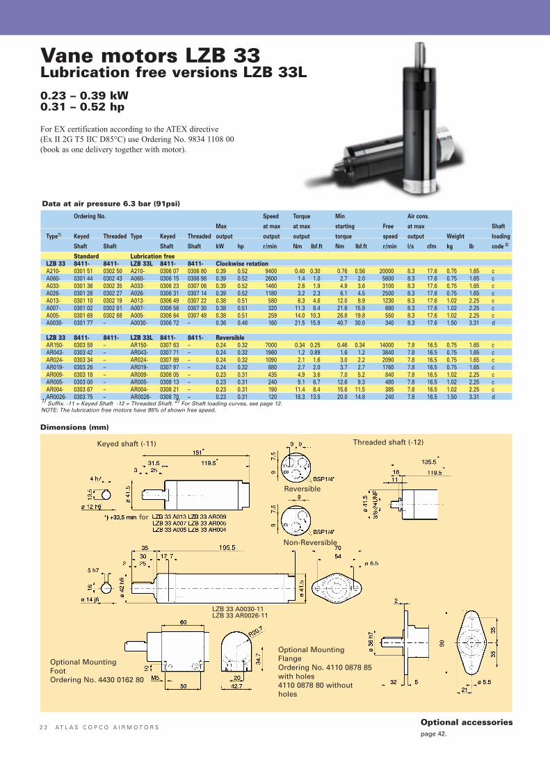
Vane motors LZB 33Lubrication free versions LZB 33L0.23 – 0.39 kW0.31 – 0.52 hp
For EX certification according to the ATEX directive (Ex II 2G T5 IIC D85°C) use Ordering No. 9834 1108 00(book as one delivery together with motor).
Ordering No. Speed Torque Min Air cons.
Max at max at max starting Free at max Shaft
Type1) Keyed Threaded Type Keyed Threaded output output output torque speed output Weight loading
Shaft Shaft Shaft Shaft kW hp r/min Nm Ibf.ft Nm Ibf.ft r/min l/s cfm kg Ib code 2)
Standard Lubrication freeLZB 33 8411- 8411- LZB 33L 8411- 8411- Clockwise rotationA210- 0301 51 0302 50 A210- 0306 07 0306 80 0.39 0.52 9400 0.40 0.30 0.76 0.56 20000 8.3 17.6 0.75 1.65 cA060- 0301 44 0302 43 A060- 0306 15 0306 98 0.39 0.52 2600 1.4 1.0 2.7 2.0 5600 8.3 17.6 0.75 1.65 cA033- 0301 36 0302 35 A033- 0306 23 0307 06 0.39 0.52 1460 2.6 1.9 4.9 3.6 3100 8.3 17.6 0.75 1.65 cA026- 0301 28 0302 27 A026- 0306 31 0307 14 0.39 0.52 1180 3.2 2.3 6.1 4.5 2500 8.3 17.6 0.75 1.65 cA013- 0301 10 0302 19 A013- 0306 49 0307 22 0.38 0.51 580 6.3 4.6 12.0 8.9 1230 8.3 17.6 1.02 2.25 cA007- 0301 02 0302 01 A007- 0306 56 0307 30 0.38 0.51 320 11.3 8.4 21.6 15.9 680 8.3 17.6 1.02 2.25 cA005- 0301 69 0302 68 A005- 0306 64 0307 48 0.38 0.51 259 14.0 10.3 26.8 19.8 550 8.3 17.6 1.02 2.25 cA0030- 0301 77 – A0030- 0306 72 – 0.36 0.48 160 21.5 15.9 40.7 30.0 340 8.3 17.6 1.50 3.31 d
LZB 33 8411- 8411- LZB 33L 8411- 8411- ReversibleAR150- 0303 59 – AR150- 0307 63 – 0.24 0.32 7000 0.34 0.25 0.46 0.34 14000 7.8 16.5 0.75 1.65 cAR043- 0303 42 – AR043- 0307 71 – 0.24 0.32 1960 1.2 0.89 1.6 1.2 3840 7.8 16.5 0.75 1.65 cAR024- 0303 34 – AR024- 0307 89 – 0.24 0.32 1090 2.1 1.6 3.0 2.2 2090 7.8 16.5 0.75 1.65 cAR019- 0303 26 – AR019- 0307 97 – 0.24 0.32 880 2.7 2.0 3.7 2.7 1760 7.8 16.5 0.75 1.65 cAR009- 0303 18 – AR009- 0308 05 – 0.23 0.31 435 4.9 3.6 7.0 5.2 840 7.8 16.5 1.02 2.25 cAR005- 0303 00 – AR005- 0308 13 – 0.23 0.31 240 9.1 6.7 12.6 9.3 480 7.8 16.5 1.02 2.25 cAR004- 0303 67 – AR004- 0308 21 – 0.23 0.31 190 11.4 8.4 15.6 11.5 385 7.8 16.5 1.02 2.25 cAR0026- 0303 75 – AR0026- 0308 70 – 0.23 0.31 120 18.3 13.5 20.0 14.8 240 7.8 16.5 1.50 3.31 d
1) Suffix. -11 = Keyed Shaft -12 = Threaded Shaft. 2) For Shaft loading curves, see page 12.NOTE: The lubrication free motors have 95% of shown free speed.
Data at air pressure 6.3 bar (91psi)
Dimensions (mm)
Keyed shaft (-11) Threaded shaft (-12)
Non-Reversible
Optional MountingFlangeOrdering No. 4110 0878 85with holes4110 0878 80 withoutholes
Reversible
Optional MountingFootOrdering No. 4430 0162 80
for
LZB 33 A0030-11LZB 33 AR0026-11
Optional accessoriespage 42.
A T L A S C O P C O A I R M O T O R S 2 3
Nm
6
5
4
3
2
1
LZB 33 A026 l/s
10
8
6
4
2
1000 2000 3000 r/min
kW
0.4
0.3
0.2
0.1
Nm
12
10
8
6
4
2
LZB 33 A013 l/s
10
8
6
4
2
300 900 1500 r/min
kW
0.4
0.3
0.2
0.1
Nm
20
16
12
8
4
LZB 33 A007 l/s
10
8
6
4
2
200 400 600 r/min
kW
0.4
0.3
0.2
0.1
800
Nm
24
20
16
12
8
4
LZB 33 A005 l/s
10
8
6
4
2
200 400 600 r/min
kW
0.4
0.3
0.2
0.1
Nm
48
36
24
12
LZB 33 A0030 l/s
12
10
8
6
4
2
100 200 400 r/min
kW
0.4
0.3
0.2
0.1
Nm
0.6
0.5
0.4
0.3
0.2
0.1
LZB 33 AR150
3000 6000 9000 r/min
kW
0.3
0.2
0.1
l/s
10
8
6
4
2
12000 15000
Nm
2.5
2.0
1.5
1.0
0.5
LZB 33 AR043
1000 2000 3000 r/min
kW
0.3
0.2
0.1
l/s
10
8
6
4
2
4000
Nm
4
3
2
1
LZB 33 AR024
500 1000 1500 r/min
kW
0.3
0.2
0.1
l/s
10
8
6
4
2
2000 2500
Nm
5
4
3
2
1
LZB 33 AR019
500 1000 1500 r/min
kW
0.3
0.2
0.1
l/s
10
8
6
4
2
2000
Nm
10
8
6
4
2
LZB 33 AR009
200 400 600 r/min
kW
0.3
0.2
0.1
l/s
10
8
6
4
2
800 1000
Nm
16
12
8
4
LZB 33 AR005
100 200 300 r/min
kW
0.3
0.2
0.1
l/s
10
8
6
4
2
500400
Nm
20
16
12
8
4
LZB 33 AR004
100 200 r/min
kW
0.3
0.2
0.1
l/s
10
8
6
4
2
400300
Nm
36
24
12
LZB 33 AR0026
100 150 r/min
kW
0.3
0.2
0.1
l/s
10
8
6
4
2
25020050
Nm
5
4
3
2
1
LZB 33 A033 l/s
10
8
6
4
2
1000 2000 3000 r/min
kW
0.4
0.3
0.2
0.1
Nm
3.2
2.8
2.4
2.0
1.6
1.2
0.8
0.4
LZB 33 A060 l/s
12
10
8
6
4
2
2000 4000 6000 r/min
kW
0.4
0.3
0.2
0.1
Nm
0.8
0.6
0.4
0.2
LZB 33 A210 l/s
10
8
6
4
2
5000 10000 15000 20000 r/min
kW
0.4
0.3
0.2
0.1
600 1200
300
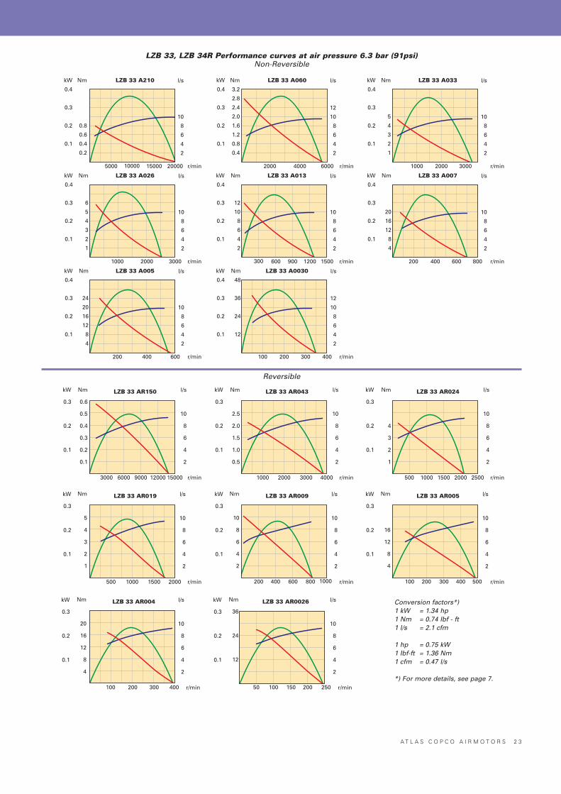
Conversion factors*)1 kW = 1.34 hp1 Nm = 0.74 Ibf - ft1 l/s = 2.1 cfm
1 hp = 0.75 kW1 Ibf-ft = 1.36 Nm1 cfm = 0.47 l/s
*) For more details, see page 7.
Reversible
LZB 33, LZB 34R Performance curves at air pressure 6.3 bar (91psi)Non-Reversible
2 4 A T L A S C O P C O A I R M O T O R S
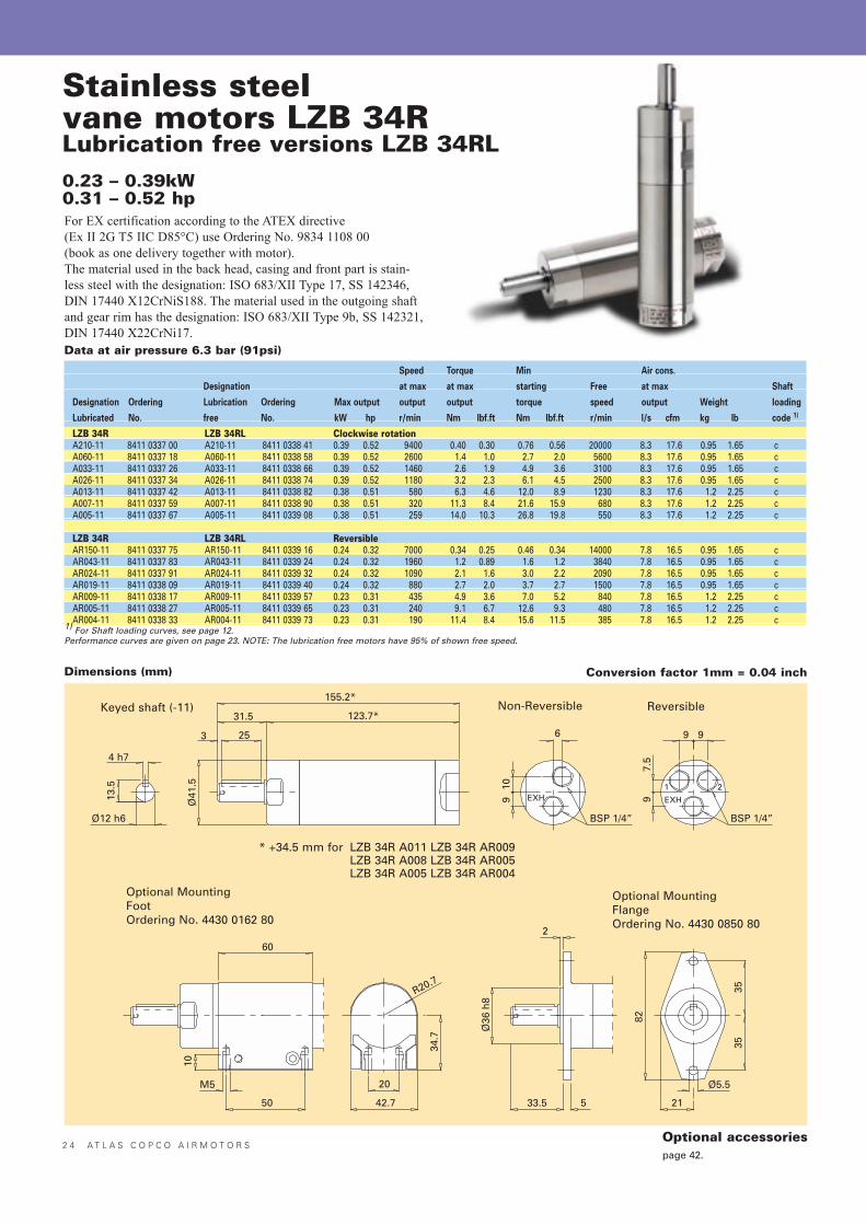
Stainless steelvane motors LZB 34RLubrication free versions LZB 34RL0.23 – 0.39kW0.31 – 0.52 hp
Speed Torque Min Air cons.
Designation at max at max starting Free at max Shaft
Designation Ordering Lubrication Ordering Max output output output torque speed output Weight loading
Lubricated No. free No. kW hp r/min Nm Ibf.ft Nm Ibf.ft r/min l/s cfm kg Ib code 1)
LZB 34R LZB 34RL Clockwise rotationA210-11 8411 0337 00 A210-11 8411 0338 41 0.39 0.52 9400 0.40 0.30 0.76 0.56 20000 8.3 17.6 0.95 1.65 cA060-11 8411 0337 18 A060-11 8411 0338 58 0.39 0.52 2600 1.4 1.0 2.7 2.0 5600 8.3 17.6 0.95 1.65 cA033-11 8411 0337 26 A033-11 8411 0338 66 0.39 0.52 1460 2.6 1.9 4.9 3.6 3100 8.3 17.6 0.95 1.65 cA026-11 8411 0337 34 A026-11 8411 0338 74 0.39 0.52 1180 3.2 2.3 6.1 4.5 2500 8.3 17.6 0.95 1.65 cA013-11 8411 0337 42 A013-11 8411 0338 82 0.38 0.51 580 6.3 4.6 12.0 8.9 1230 8.3 17.6 1.2 2.25 cA007-11 8411 0337 59 A007-11 8411 0338 90 0.38 0.51 320 11.3 8.4 21.6 15.9 680 8.3 17.6 1.2 2.25 cA005-11 8411 0337 67 A005-11 8411 0339 08 0.38 0.51 259 14.0 10.3 26.8 19.8 550 8.3 17.6 1.2 2.25 c
LZB 34R LZB 34RL ReversibleAR150-11 8411 0337 75 AR150-11 8411 0339 16 0.24 0.32 7000 0.34 0.25 0.46 0.34 14000 7.8 16.5 0.95 1.65 cAR043-11 8411 0337 83 AR043-11 8411 0339 24 0.24 0.32 1960 1.2 0.89 1.6 1.2 3840 7.8 16.5 0.95 1.65 cAR024-11 8411 0337 91 AR024-11 8411 0339 32 0.24 0.32 1090 2.1 1.6 3.0 2.2 2090 7.8 16.5 0.95 1.65 cAR019-11 8411 0338 09 AR019-11 8411 0339 40 0.24 0.32 880 2.7 2.0 3.7 2.7 1500 7.8 16.5 0.95 1.65 cAR009-11 8411 0338 17 AR009-11 8411 0339 57 0.23 0.31 435 4.9 3.6 7.0 5.2 840 7.8 16.5 1.2 2.25 cAR005-11 8411 0338 27 AR005-11 8411 0339 65 0.23 0.31 240 9.1 6.7 12.6 9.3 480 7.8 16.5 1.2 2.25 cAR004-11 8411 0338 33 AR004-11 8411 0339 73 0.23 0.31 190 11.4 8.4 15.6 11.5 385 7.8 16.5 1.2 2.25 c
1) For Shaft loading curves, see page 12.Performance curves are given on page 23. NOTE: The lubrication free motors have 95% of shown free speed.
Data at air pressure 6.3 bar (91psi)
Keyed shaft (-11) Non-Reversible
Optional MountingFlangeOrdering No. 4430 0850 80
Reversible
Optional MountingFootOrdering No. 4430 0162 80
For EX certification according to the ATEX directive (Ex II 2G T5 IIC D85°C) use Ordering No. 9834 1108 00(book as one delivery together with motor).The material used in the back head, casing and front part is stain-less steel with the designation: ISO 683/XII Type 17, SS 142346,DIN 17440 X12CrNiS188. The material used in the outgoing shaftand gear rim has the designation: ISO 683/XII Type 9b, SS 142321,DIN 17440 X22CrNi17.
Dimensions (mm) Conversion factor 1mm = 0.04 inch
* +34.5 mm for LZB 34R A011 LZB 34R AR009LZB 34R A008 LZB 34R AR005LZB 34R A005 LZB 34R AR004
Optional accessoriespage 42.
A T L A S C O P C O A I R M O T O R S 2 5
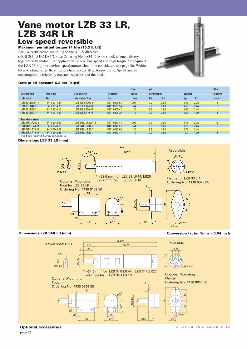
Vane motor LZB 33 LR,LZB 34R LRLow speed reversible
Free Air Shaft
Designation Ordering Designation Ordering speed consumtion Weight loading
Lubricated No. Lubrication free No. r/min l/s cfm kg lb code 1)
LZB 33 LR200-11 8411 0314 31 LZB 33L LR200-11 8411 0308 62 200 9.9 21.0 1.25 2.78 cLZB 33 LR44-11 8411 0314 23 LZB 33L LR44-11 8411 0308 54 44 9.9 21.0 1.55 3.44 cLZB 33 LR20-11 8411 0314 15 LZB 33L LR20-11 8411 0308 47 20 9.9 21.0 1.55 3.44 cLZB 33 LR10-11 8411 0314 07 LZB 33L LR10-11 8411 0308 39 10 9.9 21.0 1.80 4.00 c
Stainless steelLZB 34R LR200-11 8411 0343 02 LZB 34RL LR200-11 8411 0343 44 200 9.9 21.0 1.45 2.78 cLZB 34R LR44-11 8411 0343 10 LZB 34RL LR44-11 8411 0343 51 44 9.9 21.0 1.75 3.44 cLZB 34R LR20-11 8411 0343 28 LZB 34RL LR20-11 8411 0343 69 20 9.9 21.0 1.75 3.44 cLZB 34R LR10-11 8411 0343 36 LZB 34RL LR10-11 8411 0343 77 10 9.9 21.0 2.0 4.00 c
1) For Shaft loading curves, see page 12.
Data at air pressure 6.3 bar (91psi)
Maximum permitted torque 14 Nm (10.3 lbf.ft)For EX certification according to the ATEX directive (Ex II 2G T5 IIC D85°C) use Ordering No. 9834 1108 00 (book as one deliverytogether with motor). For applications where low speed and high torque are requiredthe LZB 33 high torque/low speed motors should be considered, see page 26. Withintheir working range these motors have a very steep torque curve. Speed and air consumption is relatively constant regardless of the load.
Dimensions LZB 33 LR (mm)
Dimensions LZB 34R LR (mm) Conversion factor 1mm = 0.04 inch
Keyed shaft (-11)
Optional MountingFlangeOrdering No. 4430 0850 80
Reversible
Optional MountingFootOrdering No. 4430 0855 80
* +34.5 mm for LZB 34R LR 44 LZB 34R LR20+69 mm for LZB 34R LR 10
Optional MountingFoot for LZB 33 LROrdering No. 4430 0162 80
* +33.5 mm for LZB 33 LR44, LR20+67 mm for LZB 33 LR10
Reversible
Flange for LZB 33 LROrdering No. 4110 0878 85
Optional accessoriespage 42.
2 6 A T L A S C O P C O A I R M O T O R S
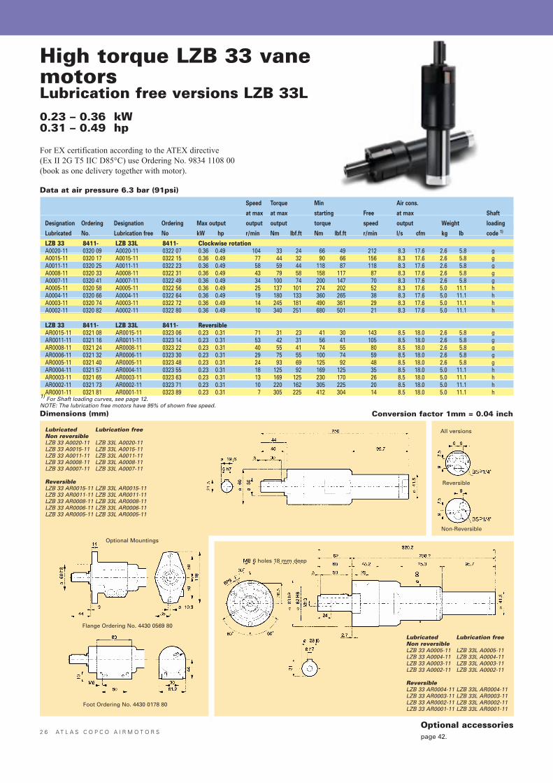
High torque LZB 33 vanemotorsLubrication free versions LZB 33L0.23 – 0.36 kW0.31 – 0.49 hp
For EX certification according to the ATEX directive (Ex II 2G T5 IIC D85°C) use Ordering No. 9834 1108 00(book as one delivery together with motor).
Speed Torque Min Air cons.
at max at max starting Free at max Shaft
Designation Ordering Designation Ordering Max output output output torque speed output Weight loading
Lubricated No. Lubrication free No kW hp r/min Nm Ibf.ft Nm Ibf.ft r/min l/s cfm kg lb code 1)
LZB 33 8411- LZB 33L 8411- Clockwise rotationA0020-11 0320 09 A0020-11 0322 07 0.36 0.49 104 33 24 66 49 212 8.3 17.6 2.6 5.8 gA0015-11 0320 17 A0015-11 0322 15 0.36 0.49 77 44 32 90 66 156 8.3 17.6 2.6 5.8 gA0011-11 0320 25 A0011-11 0322 23 0.36 0.49 58 59 44 118 87 118 8.3 17.6 2.6 5.8 gA0008-11 0320 33 A0008-11 0322 31 0.36 0.49 43 79 58 158 117 87 8.3 17.6 2.6 5.8 gA0007-11 0320 41 A0007-11 0322 49 0.36 0.49 34 100 74 200 147 70 8.3 17.6 2.6 5.8 gA0005-11 0320 58 A0005-11 0322 56 0.36 0.49 25 137 101 274 202 52 8.3 17.6 5.0 11.1 hA0004-11 0320 66 A0004-11 0322 64 0.36 0.49 19 180 133 360 265 38 8.3 17.6 5.0 11.1 hA0003-11 0320 74 A0003-11 0322 72 0.36 0.49 14 245 181 490 361 29 8.3 17.6 5.0 11.1 hA0002-11 0320 82 A0002-11 0322 80 0.36 0.49 10 340 251 680 501 21 8.3 17.6 5.0 11.1 h
LZB 33 8411- LZB 33L 8411- ReversibleAR0015-11 0321 08 AR0015-11 0323 06 0.23 0.31 71 31 23 41 30 143 8.5 18.0 2.6 5.8 gAR0011-11 0321 16 AR0011-11 0323 14 0.23 0.31 53 42 31 56 41 105 8.5 18.0 2.6 5.8 gAR0008-11 0321 24 AR0008-11 0323 22 0.23 0.31 40 55 41 74 55 80 8.5 18.0 2.6 5.8 gAR0006-11 0321 32 AR0006-11 0323 30 0.23 0.31 29 75 55 100 74 59 8.5 18.0 2.6 5.8 gAR0005-11 0321 40 AR0005-11 0323 48 0.23 0.31 24 93 69 125 92 48 8.5 18.0 2.6 5.8 gAR0004-11 0321 57 AR0004-11 0323 55 0.23 0.31 18 125 92 169 125 35 8.5 18.0 5.0 11.1 hAR0003-11 0321 65 AR0003-11 0323 63 0.23 0.31 13 169 125 230 170 26 8.5 18.0 5.0 11.1 hAR0002-11 0321 73 AR0002-11 0323 71 0.23 0.31 10 220 162 305 225 20 8.5 18.0 5.0 11.1 hAR0001-11 0321 81 AR0001-11 0323 89 0.23 0.31 7 305 225 412 304 14 8.5 18.0 5.0 11.1 h
1) For Shaft loading curves, see page 12.NOTE: The lubrication free motors have 95% of shown free speed.
Data at air pressure 6.3 bar (91psi)
Dimensions (mm) Conversion factor 1mm = 0.04 inch
Lubricated Lubrication freeNon reversibleLZB 33 A0020-11 LZB 33L A0020-11LZB 33 A0015-11 LZB 33L A0015-11LZB 33 A0011-11 LZB 33L A0011-11LZB 33 A0008-11 LZB 33L A0008-11LZB 33 A0007-11 LZB 33L A0007-11
ReversibleLZB 33 AR0015-11 LZB 33L AR0015-11LZB 33 AR0011-11 LZB 33L AR0011-11LZB 33 AR0008-11 LZB 33L AR0008-11LZB 33 AR0006-11 LZB 33L AR0006-11LZB 33 AR0005-11 LZB 33L AR0005-11
Lubricated Lubrication freeNon reversibleLZB 33 A0005-11 LZB 33L A0005-11LZB 33 A0004-11 LZB 33L A0004-11LZB 33 A0003-11 LZB 33L A0003-11LZB 33 A0002-11 LZB 33L A0002-11
ReversibleLZB 33 AR0004-11 LZB 33L AR0004-11LZB 33 AR0003-11 LZB 33L AR0003-11LZB 33 AR0002-11 LZB 33L AR0002-11LZB 33 AR0001-11 LZB 33L AR0001-11
Reversible
All versions
Non-Reversible
Optional Mountings
Flange Ordering No. 4430 0569 80
Foot Ordering No. 4430 0178 80
6 holes 18 mm deep
Optional accessoriespage 42.
A T L A S C O P C O A I R M O T O R S 2 7
Nm LZB 33 A0020 l/s
r/min
kW0.40
0.35
0.30
0.25
0.20
0.15
0.10
0.05
70
60
50
40
30
20
10
10
8
6
4
2
10050 150 200 250
Nm LZB 33 A0015 l/s
r/min
kW0.40
0.35
0.30
0.25
0.20
0.15
0.10
0.05
100
80
60
40
20
10
8
6
4
2
20 40 60 80 100 120 140 160
Nm LZB 33 A0011 l/s
r/min
kW0.40
0.35
0.30
0.25
0.20
0.15
0.10
0.05
120
100
80
60
40
20
10
8
6
4
2
20 40 60 80 100 120
Nm LZB 33 A0008 l/s
r/min
kW0.40
0.35
0.30
0.25
0.20
0.15
0.10
0.05
160
140
120
100
80
60
40
20
10
8
6
4
2
20 40 60 80 100
Nm LZB 33 A0007 l/s
r/min
kW0.40
0.35
0.30
0.25
0.20
0.15
0.10
0.05
200
175
150
125
100
75
50
25
10
8
6
4
2
20 30 60 70504010
Nm LZB 33 A0005 l/s
r/min
kW0.40
0.35
0.30
0.25
0.20
0.15
0.10
0.05
300
250
200
150
100
50
10
8
6
4
2
20 30 60504010
Nm LZB 33 A0004 l/s
r/min
kW0.40
0.35
0.30
0.25
0.20
0.15
0.10
0.05
400
350
300
250
200
150
100
50
10
8
6
4
2
10 15 3025205 35 40
Nm LZB 33 A0003 l/s
r/min
kW0.40
0.35
0.30
0.25
0.20
0.15
0.10
0.05
500
400
300
200
100
10
8
6
4
2
10 15 3025205
Nm LZB 33 A0002 l/s
r/min
kW0.40
0.35
0.30
0.25
0.20
0.15
0.10
0.05
700
600
500
400
300
200
100
10
8
6
4
2
10 15 25205
Nm LZB 33 AR0015 l/s
r/min
kW0.25
0.20
0.15
0.10
0.05
60
40
20
12
8
4
60 90 15012030
Nm LZB 33 AR0011 l/s
r/min
kW0.25
0.20
0.15
0.10
0.05
80
60
40
20
12
8
4
40 60 1208020 100
Nm LZB 33 AR0008 l/s
r/min
kW0.25
0.20
0.15
0.10
0.05
120
80
40
12
8
4
40 60 802010 30 50 70
Nm LZB 33 AR0006 l/s
r/min
kW0.25
0.20
0.15
0.10
0.05
160
120
80
40
12
8
4
40 602010 30 50
Nm LZB 33 AR0005 l/s
r/min
kW0.25
0.20
0.15
0.10
0.05
200
160
120
80
40
12
8
4
402010 30 50
Nm LZB 33 AR0004 l/s
r/min
kW0.25
0.20
0.15
0.10
0.05
250
200
150
100
50
12
8
4
252010 30 35155
Nm LZB 33 AR0003 l/s
r/min
kW0.25
0.20
0.15
0.10
0.05
400
300
200
100
12
8
4
252010 30155
Nm LZB 33 AR0002 l/s
r/min
kW0.25
0.20
0.15
0.10
0.05
500
400
300
200
100
12
8
4
16128 204
Nm LZB 33 AR0001 l/s
r/min
kW0.25
0.20
0.15
0.10
0.05
600
400
200
12
8
4
864 162 10 12 14
Reversible
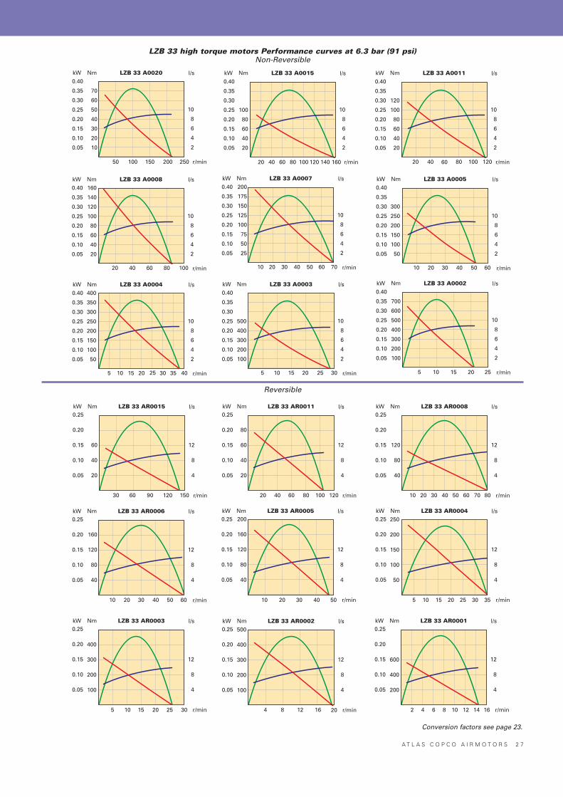
LZB 33 high torque motors Performance curves at 6.3 bar (91 psi)Non-Reversible
Conversion factors see page 23.
2 8 A T L A S C O P C O A I R M O T O R S
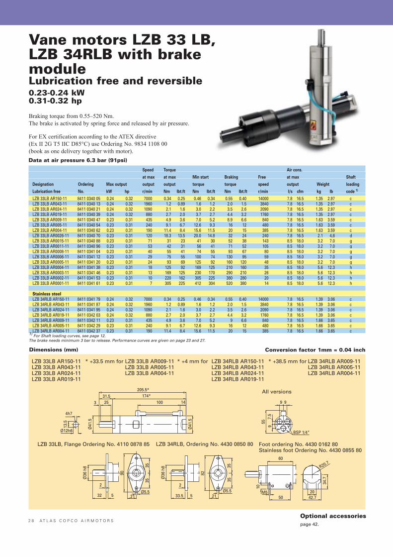
Vane motors LZB 33 LB,LZB 34RLB with brakemoduleLubrication free and reversible
Speed Torque Air cons.
at max at max Min start Braking Free at max Shaft
Designation Ordering Max output output output torque torque speed output Weight loading
Lubrication free No. kW hp r/min Nm lbt.ft Nm lbt.ft Nm lbt.ft r/min l/s cfm kg lb code 1)
LZB 33LB AR150-11 8411 0340 05 0.24 0.32 7000 0.34 0.25 0.46 0.34 0.55 0.40 14000 7.8 16.5 1.35 2.97 cLZB 33LB AR043-11 8411 0340 13 0.24 0.32 1960 1.2 0.89 1.6 1.2 2.0 1.5 3840 7.8 16.5 1.35 2.97 cLZB 33LB AR024-11 8411 0340 21 0.24 0.32 1090 2.1 1.6 3.0 2.2 3.5 2.6 2090 7.8 16.5 1.35 2.97 c LZB 33LB AR019-11 8411 0340 39 0.24 0.32 880 2.7 2.0 3.7 2.7 4.4 3.2 1760 7.8 16.5 1.35 2.97 cLZB 33LB AR009-11 8411 0340 47 0.23 0.31 435 4.9 3.6 7.0 5.2 8.9 6.6 840 7.8 16.5 1.63 3.59 cLZB 33LB AR005-11 8411 0340 54 0.23 0.31 240 9.1 6.7 12.6 9.3 16 12 480 7.8 16.5 1.63 3.59 cLZB 33LB AR004-11 8411 0340 62 0.23 0.31 190 11.4 8.4 15.6 11.5 20 15 385 7.8 16.5 1.63 3.59 cLZB 33LB AR0026-11 8411 0340 70 0.23 0.31 120 18.3 13.5 20.0 14.8 32 24 240 7.8 16.5 2.1 4,6 dLZB 33LB AR0015-11 8411 0340 88 0.23 0.31 71 31 23 41 30 52 38 143 8.5 18.0 3.2 7.0 gLZB 33LB AR0011-11 8411 0340 96 0.23 0.31 53 42 31 56 41 71 52 105 8.5 18.0 3.2 7.0 gLZB 33LB AR0008-11 8411 0341 04 0.23 0.31 40 55 41 74 55 93 67 80 8.5 18.0 3.2 7.0 gLZB 33LB AR0006-11 8411 0341 12 0.23 0.31 29 75 55 100 74 130 95 59 8.5 18.0 3.2 7.0 gLZB 33LB AR0005-11 8411 0341 20 0.23 0.31 24 93 69 125 92 160 120 48 8.5 18.0 3.2 7.0 gLZB 33LB AR0004-11 8411 0341 38 0.23 0.31 18 125 92 169 125 210 160 35 8.5 18.0 5.6 12.3 hLZB 33LB AR0003-11 8411 0341 46 0.23 0.31 13 169 125 230 170 290 210 26 8.5 18.0 5.6 12.3 hLZB 33LB AR0002-11 8411 0341 53 0.23 0.31 10 220 162 305 225 380 280 20 8.5 18.0 5.6 12.3 hLZB 33LB AR0001-11 8411 0341 61 0.23 0.31 7 305 225 412 304 520 380 14 8.5 18.0 5.6 12.3 h
Stainless steelLZB 34RLB AR150-11 8411 0341 79 0.24 0.32 7000 0.34 0.25 0.46 0.34 0.55 0.40 14000 7.8 16.5 1.39 3.06 cLZB 34RLB AR043-11 8411 0341 87 0.24 0.32 1960 1.2 0.89 1.6 1.2 2.0 1.5 3840 7.8 16.5 1.39 3.06 cLZB 34RLB AR024-11 8411 0341 95 0.24 0.32 1090 2.1 1.6 3.0 2.2 3.5 2.6 2090 7.8 16.5 1.39 3.06 cLZB 34RLB AR019-11 8411 0342 03 0.24 0.32 880 2.7 2.0 3.7 2.7 4.4 3.2 1760 7.8 16.5 1.39 3.06 cLZB 34RLB AR009-11 8411 0342 11 0.23 0.31 435 4.9 3.6 7.0 5.2 9 6.6 840 7.8 16.5 1.66 3.65 cLZB 34RLB AR005-11 8411 0342 29 0.23 0.31 240 9.1 6.7 12.6 9.3 16 12 480 7.8 16.5 1.66 3.65 cLZB 34RLB AR004-11 8411 0342 37 0.23 0.31 190 11.4 8.4 15.6 11.5 20 15 385 7.8 16.5 1.66 3.65 c
1) For Shaft loading curves, see page 12.The brake needs minimum 3 bar to release. Performance curves are given on page 23 and 27.
Data at air pressure 6.3 bar (91psi)
0.23-0.24 kW0.31-0.32 hp
Braking torque from 0.55�520 Nm.The brake is activated by spring force and released by air pressure.
For EX certification according to the ATEX directive (Ex II 2G T5 IIC D85°C) use Ordering No. 9834 1108 00(book as one delivery together with motor).
LZB 33LB AR150-11 * +33.5 mm for LZB 33LB AR009-11LZB 33LB AR043-11 LZB 33LB AR005-11LZB 33LB AR024-11 LZB 33LB AR004-11LZB 33LB AR019-11
All versions
LZB 33LB, Flange Ordering No. 4110 0878 85 LZB 34RLB, Ordering No. 4430 0850 80 Foot ordering No. 4430 0162 80Stainless foot Ordering No. 4430 0855 80
* +4 mm for LZB 34RLB AR150-11LZB 34RLB AR043-11LZB 34RLB AR024-11LZB 34RLB AR019-11
* +38.5 mm for LZB 34RLB AR009-11LZB 34RLB AR005-11LZB 34RLB AR004-11
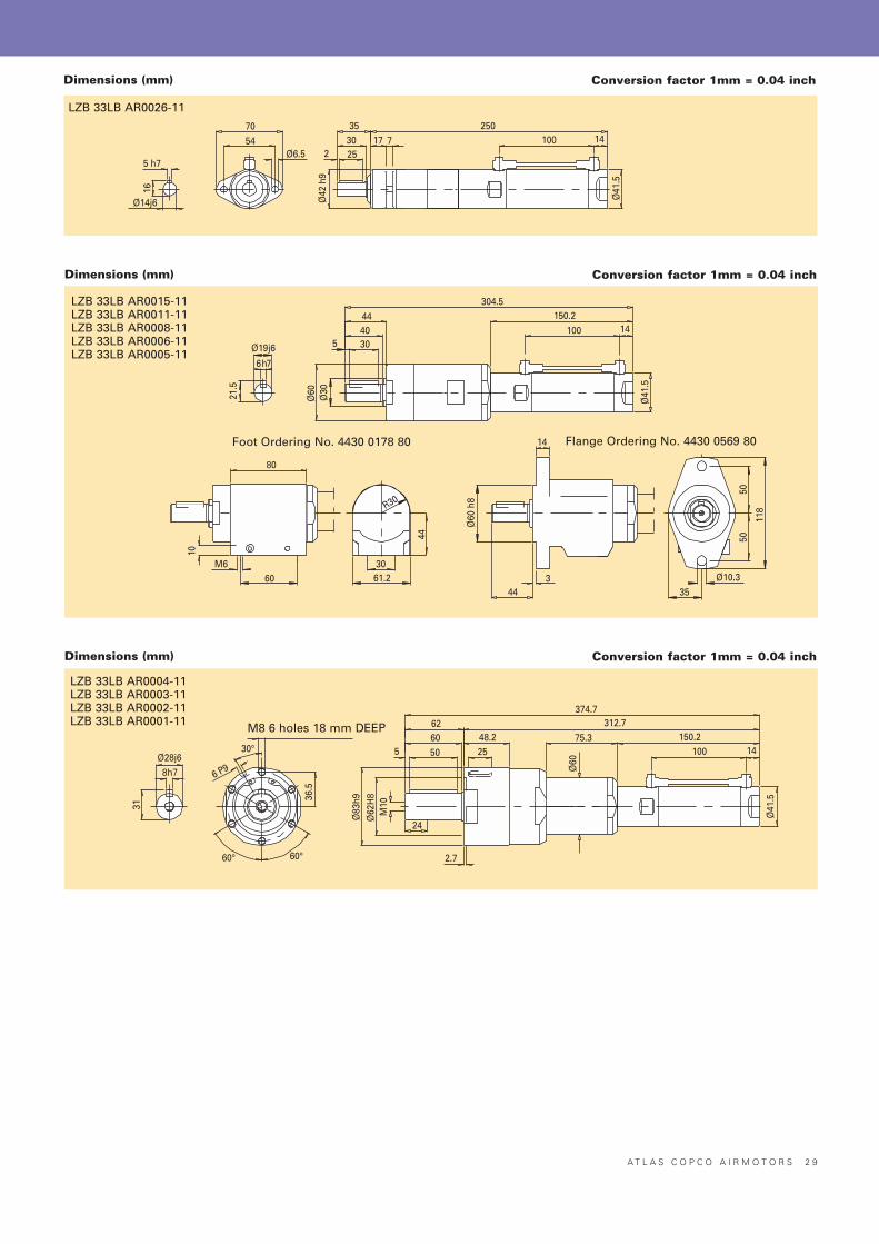
Dimensions (mm) Conversion factor 1mm = 0.04 inch
Optional accessoriespage 42.
A T L A S C O P C O A I R M O T O R S 2 9
Dimensions (mm) Conversion factor 1mm = 0.04 inch
LZB 33LB AR0026-11
Dimensions (mm) Conversion factor 1mm = 0.04 inch
100
LZB 33LB AR0015-11LZB 33LB AR0011-11LZB 33LB AR0008-11LZB 33LB AR0006-11LZB 33LB AR0005-11
Foot Ordering No. 4430 0178 80 Flange Ordering No. 4430 0569 80
Dimensions (mm) Conversion factor 1mm = 0.04 inch
LZB 33LB AR0004-11LZB 33LB AR0003-11LZB 33LB AR0002-11LZB 33LB AR0001-11 M8 6 holes 18 mm DEEP
3 0 A T L A S C O P C O A I R M O T O R S
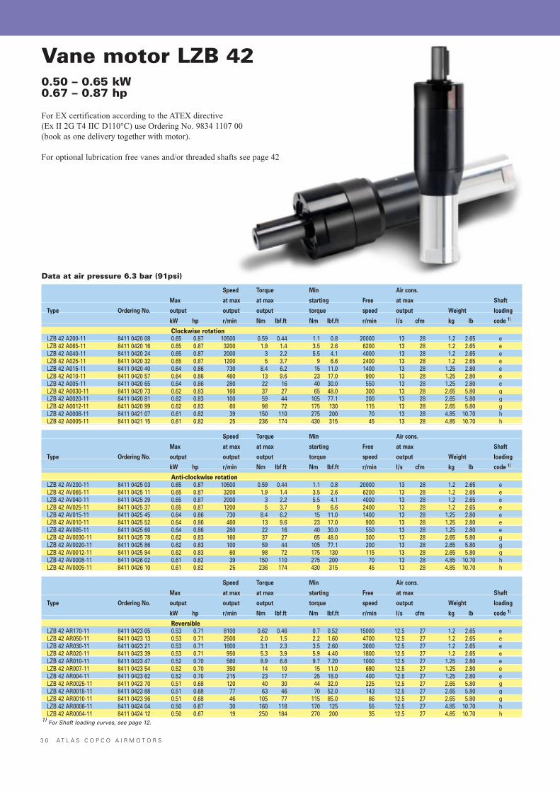
Vane motor LZB 420.50 – 0.65 kW0.67 – 0.87 hp
For EX certification according to the ATEX directive (Ex II 2G T4 IIC D110°C) use Ordering No. 9834 1107 00(book as one delivery together with motor).
For optional lubrication free vanes and/or threaded shafts see page 42
Speed Torque Min Air cons.
Max at max at max starting Free at max Shaft
Type Ordering No. output output output torque speed output Weight loading
kW hp r/min Nm lbf.ft Nm lbf.ft r/min l/s cfm kg lb code 1)
Clockwise rotationLZB 42 A200-11 8411 0420 08 0.65 0.87 10500 0.59 0.44 1.1 0.8 20000 13 28 1.2 2.65 eLZB 42 A065-11 8411 0420 16 0.65 0.87 3200 1.9 1.4 3.5 2.6 6200 13 28 1.2 2.65 eLZB 42 A040-11 8411 0420 24 0.65 0.87 2000 3 2.2 5.5 4.1 4000 13 28 1.2 2.65 eLZB 42 A025-11 8411 0420 32 0.65 0.87 1200 5 3.7 9 6.6 2400 13 28 1.2 2.65 eLZB 42 A015-11 8411 0420 40 0.64 0.86 730 8.4 6.2 15 11.0 1400 13 28 1.25 2.80 eLZB 42 A010-11 8411 0420 57 0.64 0.86 460 13 9.6 23 17.0 900 13 28 1.25 2.80 eLZB 42 A005-11 8411 0420 65 0.64 0.86 280 22 16 40 30.0 550 13 28 1.25 2.80 eLZB 42 A0030-11 8411 0420 73 0.62 0.83 160 37 27 65 48.0 300 13 28 2.65 5.80 gLZB 42 A0020-11 8411 0420 81 0.62 0.83 100 59 44 105 77.1 200 13 28 2.65 5.80 gLZB 42 A0012-11 8411 0420 99 0.62 0.83 60 98 72 175 130 115 13 28 2.65 5.80 gLZB 42 A0008-11 8411 0421 07 0.61 0.82 39 150 110 275 200 70 13 28 4.85 10.70 hLZB 42 A0005-11 8411 0421 15 0.61 0.82 25 236 174 430 315 45 13 28 4.85 10.70 h
Speed Torque Min Air cons.
Max at max at max starting Free at max Shaft
Type Ordering No. output output output torque speed output Weight loading
kW hp r/min Nm lbf.ft Nm lbf.ft r/min l/s cfm kg lb code 1)
Anti-clockwise rotationLZB 42 AV200-11 8411 0425 03 0.65 0.87 10500 0.59 0.44 1.1 0.8 20000 13 28 1.2 2.65 eLZB 42 AV065-11 8411 0425 11 0.65 0.87 3200 1.9 1.4 3.5 2.6 6200 13 28 1.2 2.65 eLZB 42 AV040-11 8411 0425 29 0.65 0.87 2000 3 2.2 5.5 4.1 4000 13 28 1.2 2.65 eLZB 42 AV025-11 8411 0425 37 0.65 0.87 1200 5 3.7 9 6.6 2400 13 28 1.2 2.65 eLZB 42 AV015-11 8411 0425 45 0.64 0.86 730 8.4 6.2 15 11.0 1400 13 28 1.25 2.80 eLZB 42 AV010-11 8411 0425 52 0.64 0.86 460 13 9.6 23 17.0 900 13 28 1.25 2.80 eLZB 42 AV005-11 8411 0425 60 0.64 0.86 280 22 16 40 30.0 550 13 28 1.25 2.80 eLZB 42 AV0030-11 8411 0425 78 0.62 0.83 160 37 27 65 48.0 300 13 28 2.65 5.80 gLZB 42 AV0020-11 8411 0425 86 0.62 0.83 100 59 44 105 77.1 200 13 28 2.65 5.80 gLZB 42 AV0012-11 8411 0425 94 0.62 0.83 60 98 72 175 130 115 13 28 2.65 5.80 gLZB 42 AV0008-11 8411 0426 02 0.61 0.82 39 150 110 275 200 70 13 28 4.85 10.70 hLZB 42 AV0005-11 8411 0426 10 0.61 0.82 25 236 174 430 315 45 13 28 4.85 10.70 h
Speed Torque Min Air cons.
Max at max at max starting Free at max Shaft
Type Ordering No. output output output torque speed output Weight loading
kW hp r/min Nm lbf.ft Nm lbf.ft r/min l/s cfm kg lb code 1)
ReversibleLZB 42 AR170-11 8411 0423 05 0.53 0.71 8100 0.62 0.46 0.7 0.52 15000 12.5 27 1.2 2.65 eLZB 42 AR050-11 8411 0423 13 0.53 0.71 2500 2.0 1.5 2.2 1.60 4700 12.5 27 1.2 2.65 eLZB 42 AR030-11 8411 0423 21 0.53 0.71 1600 3.1 2.3 3.5 2.60 3000 12.5 27 1.2 2.65 eLZB 42 AR020-11 8411 0423 39 0.53 0.71 950 5.3 3.9 5.9 4.40 1800 12.5 27 1.2 2.65 eLZB 42 AR010-11 8411 0423 47 0.52 0.70 560 8.9 6.6 9.7 7.20 1000 12.5 27 1.25 2.80 eLZB 42 AR007-11 8411 0423 54 0.52 0.70 350 14 10 15 11.0 690 12.5 27 1.25 2.80 eLZB 42 AR004-11 8411 0423 62 0.52 0.70 215 23 17 25 18.0 400 12.5 27 1.25 2.80 eLZB 42 AR0025-11 8411 0423 70 0.51 0.68 120 40 30 44 32.0 225 12.5 27 2.65 5.80 gLZB 42 AR0015-11 8411 0423 88 0.51 0.68 77 63 46 70 52.0 143 12.5 27 2.65 5.80 gLZB 42 AR0010-11 8411 0423 96 0.51 0.68 46 105 77 115 85.0 86 12.5 27 2.65 5.80 gLZB 42 AR0006-11 8411 0424 04 0.50 0.67 30 160 118 170 125 55 12.5 27 4.85 10.70 hLZB 42 AR0004-11 8411 0424 12 0.50 0.67 19 250 184 270 200 35 12.5 27 4.85 10.70 h
1) For Shaft loading curves, see page 12.
Data at air pressure 6.3 bar (91psi)
A T L A S C O P C O A I R M O T O R S 3 1
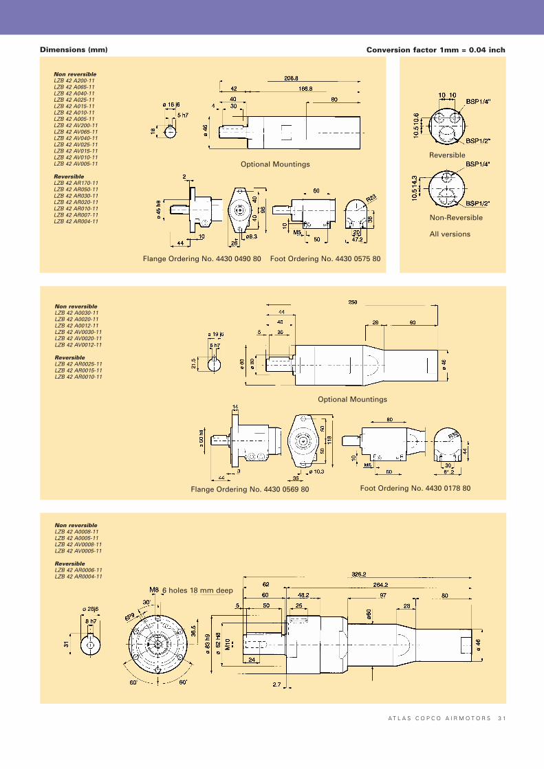
Dimensions (mm) Conversion factor 1mm = 0.04 inch
Non reversibleLZB 42 A200-11LZB 42 A065-11LZB 42 A040-11LZB 42 A025-11LZB 42 A015-11LZB 42 A010-11LZB 42 A005-11LZB 42 AV200-11LZB 42 AV065-11LZB 42 AV040-11LZB 42 AV025-11LZB 42 AV015-11LZB 42 AV010-11LZB 42 AV005-11
ReversibleLZB 42 AR170-11LZB 42 AR050-11LZB 42 AR030-11LZB 42 AR020-11LZB 42 AR010-11LZB 42 AR007-11LZB 42 AR004-11
Non reversibleLZB 42 A0030-11LZB 42 A0020-11LZB 42 A0012-11LZB 42 AV0030-11LZB 42 AV0020-11LZB 42 AV0012-11
ReversibleLZB 42 AR0025-11LZB 42 AR0015-11LZB 42 AR0010-11
Non reversibleLZB 42 A0008-11LZB 42 A0005-11LZB 42 AV0008-11LZB 42 AV0005-11
ReversibleLZB 42 AR0006-11LZB 42 AR0004-11
Optional Mountings
Flange Ordering No. 4430 0490 80 Foot Ordering No. 4430 0575 80
Optional Mountings
Flange Ordering No. 4430 0569 80 Foot Ordering No. 4430 0178 80
6 holes 18 mm deep
Reversible
Non-Reversible
All versions
3 2 A T L A S C O P C O A I R M O T O R S
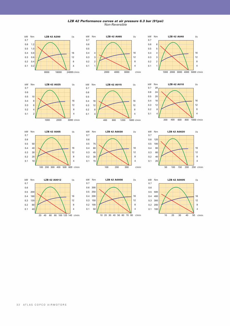
Nm LZB 42 A200 l/s
r/min
kW0.7
0.6
0.5
0.4
0.3
0.2
0.1
1.2
1.0
0.8
0.6
0.4
0.2
16
12
8
4
8000 16000 24000
Nm LZB 42 A065 l/s
r/min
kW0.7
0.6
0.5
0.4
0.3
0.2
0.1
4
3
2
1
16
12
8
4
2000 4000 6000
Nm LZB 42 A040 l/s
r/min
kW0.7
0.6
0.5
0.4
0.3
0.2
0.1
6
5
4
3
2
1
16
12
8
4
1000 2000 40003000 5000
Nm LZB 42 A025 l/s
r/min
kW0.7
0.6
0.5
0.4
0.3
0.2
0.1
10
8
6
4
2
16
12
8
4
1000 2000 3000
Nm LZB 42 A015 l/s
r/min
kW0.7
0.6
0.5
0.4
0.3
0.2
0.1
16
12
8
4
16
12
8
4
400 800 1200 1600
Nm LZB 42 A010 l/s
r/min
kW0.7
0.6
0.5
0.4
0.3
0.2
0.1
28
24
20
16
12
8
4
16
12
8
4
200 400 600 1000800
Nm LZB 42 A005 l/s
r/min
kW0.7
0.6
0.5
0.4
0.3
0.2
0.1
50
40
30
20
10
16
12
8
4
100 200 300 600400 500
Nm LZB 42 A0030 l/s
r/min
kW0.7
0.6
0.5
0.4
0.3
0.2
0.1
75
60
45
30
15
16
12
8
4
100 200 300
Nm LZB 42 A0020 l/s
r/min
kW0.7
0.6
0.5
0.4
0.3
0.2
0.1
120
100
80
60
40
20
16
12
8
4
50 100 150
Nm LZB 42 A0012 l/s
r/min
kW0.7
0.6
0.5
0.4
0.3
0.2
0.1
200
160
120
80
40
16
12
8
4
20 80 12040 60 100 140
Nm LZB 42 A0008 l/s
r/min
kW0.7
0.6
0.5
0.4
0.3
0.2
0.1
300
250
200
150
100
50
16
12
8
4
10 40 6020 30 50 70 80
Nm LZB 42 A0005 l/s
r/min
kW0.7
0.6
0.5
0.4
0.3
0.2
0.1
500
400
300
200
100
16
12
8
4
10 4020 30 50
200 250
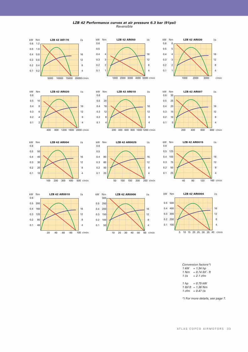
LZB 42 Performance curves at air pressure 6.3 bar (91psi)Non-Reversible
A T L A S C O P C O A I R M O T O R S 3 3
Nm LZB 42 AR170 l/s
r/min
kW0.6
0.5
0.4
0.3
0.2
0.1
1.2
1.0
0.8
0.6
0.4
0.2
16
12
8
4
5000 10000 2000015000
Nm LZB 42 AR050 l/s
r/min
kW0.6
0.5
0.4
0.3
0.2
0.1
4
3
2
1
16
12
8
4
1000 2000 40003000 5000
Nm LZB 42 AR030 l/s
r/min
kW0.6
0.5
0.4
0.3
0.2
0.1
6
5
4
3
2
1
16
12
8
4
1000 2000 3000
Nm LZB 42 AR020 l/s
r/min
kW0.6
0.5
0.4
0.3
0.2
0.1
10
8
6
4
2
16
12
8
4
400 800 16001200 2000
Nm LZB 42 AR010 l/s
r/min
kW0.6
0.5
0.4
0.3
0.2
0.1
20
16
12
8
4
16
12
8
4
200 400 800600 1200
Nm LZB 42 AR007 l/s
r/min
kW0.6
0.5
0.4
0.3
0.2
0.1
30
25
20
15
10
5
16
12
8
4
200 400 600 800
Nm LZB 42 AR004 l/s
r/min
kW0.6
0.5
0.4
0.3
0.2
0.1
50
40
30
20
10
16
12
8
4
100 200 300 500400
Nm LZB 42 AR0025 l/s
r/min
kW0.6
0.5
0.4
0.3
0.2
0.1
80
60
40
20
16
12
8
4
50 100 150 250200
Nm LZB 42 AR0015 l/s
r/min
kW0.6
0.5
0.4
0.3
0.2
0.1
125
100
75
50
25
16
12
8
4
40 80 120 160
Nm LZB 42 AR0010 l/s
r/min
kW0.6
0.5
0.4
0.3
0.2
0.1
200
160
120
80
40
16
12
8
4
20 40 80 10060
Nm LZB 42 AR0006 l/s
r/min
kW
0.5
0.4
0.3
0.2
0.1
300
250
200
150
100
50
16
12
8
4
10 20 40 6030 50
Nm LZB 42 AR0004 l/s
r/min
kW
0.5
0.4
0.3
0.2
0.1
500
400
300
200
100
16
12
8
4
5 10 20 4015 25 30 35
1000
LZB 42 Performance curves at air pressure 6.3 bar (91psi)Reversible
Conversion factors*)1 kW = 1.34 hp1 Nm = 0.74 Ibf - ft1 l/s = 2.1 cfm
1 hp = 0.75 kW1 Ibf-ft = 1.36 Nm1 cfm = 0.47 l/s
*) For more details, see page 7.
3 4 A T L A S C O P C O A I R M O T O R S
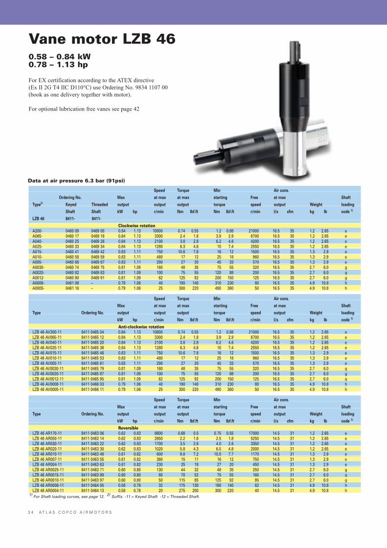
Vane motor LZB 460.58 – 0.84 kW0.78 – 1.13 hp
For EX certification according to the ATEX directive (Ex II 2G T4 IIC D110°C) use Ordering No. 9834 1107 00(book as one delivery together with motor).
For optional lubrication free vanes see page 42
Speed Torque Min Air cons.
Ordering No. Max at max at max starting Free at max Shaft
Type2) Keyed Threaded output output output torque speed output Weight loading
Shaft Shaft kW hp r/min Nm lbf.ft Nm lbf.ft r/min l/s cfm kg lb code 1)
LZB 46 8411- 8411-
Clockwise rotationA200- 0460 09 0469 00 0.84 1.13 10800 0.74 0.55 1.2 0.88 21000 16.5 35 1.2 2.65 eA065- 0460 17 0469 18 0.84 1.13 3300 2.4 1.8 3.9 2.9 6700 16.5 35 1.2 2.65 eA040- 0460 25 0469 26 0.84 1.13 2100 3.8 2.8 6.2 4.6 4200 16.5 35 1.2 2.65 eA025- 0460 33 0469 34 0.84 1.13 1280 6.3 4.6 10 7.4 2550 16.5 35 1.2 2.65 eA015- 0460 41 0469 42 0.83 1.11 750 10.6 7.8 16 12 1500 16.5 35 1.3 2.9 eA010- 0460 58 0469 59 0.83 1.11 480 17 12 25 18 960 16.5 35 1.3 2.9 eA005- 0460 66 0469 67 0.83 1.11 290 27 20 45 33 570 16.5 35 1.3 2.9 eA0030- 0460 74 0469 75 0.81 1.09 160 48 35 75 55 320 16.5 35 2.7 6.0 gA0020- 0460 82 0469 83 0.81 1.09 100 75 55 120 88 200 16.5 35 2.7 6.0 gA0012- 0460 90 0469 91 0.81 1.09 62 125 92 200 150 125 16.5 35 2.7 6.0 gA0008- 0461 08 – 0.79 1.06 40 190 140 310 230 80 16.5 35 4.9 10.8 hA0005- 0461 16 – 0.79 1.06 25 300 220 490 360 50 16.5 35 4.9 10.8 h
Speed Torque Min Air cons.
Max at max at max starting Free at max Shaft
Type Ordering No. output output output torque speed output Weight loading
kW hp r/min Nm lbf.ft Nm lbf.ft r/min l/s cfm kg lb code 1)
Anti-clockwise rotationLZB 46 AV200-11 8411 0465 04 0.84 1.13 10800 0.74 0.55 1.2 0.88 21000 16.5 35 1.2 2.65 eLZB 46 AV065-11 8411 0465 12 0.84 1.13 3300 2.4 1.8 3.9 2.9 6700 16.5 35 1.2 2.65 eLZB 46 AV040-11 8411 0465 20 0.84 1.13 2100 3.8 2.8 6.2 4.6 4200 16.5 35 1.2 2.65 eLZB 46 AV025-11 8411 0465 38 0.84 1.13 1280 6.3 4.6 10 7.4 2550 16.5 35 1.2 2.65 eLZB 46 AV015-11 8411 0465 46 0.83 1.11 750 10.6 7.8 16 12 1500 16.5 35 1.3 2.9 eLZB 46 AV010-11 8411 0465 53 0.83 1.11 480 17 12 25 18 960 16.5 35 1.3 2.9 eLZB 46 AV005-11 8411 0465 61 0.83 1.11 290 27 20 45 33 570 16.5 35 1.3 2.9 eLZB 46 AV0030-11 8411 0465 79 0.81 1.09 160 48 35 75 55 320 16.5 35 2.7 6.0 gLZB 46 AV0020-11 8411 0465 87 0.81 1.09 100 75 55 120 88 200 16.5 35 2.7 6.0 gLZB 46 AV0012-11 8411 0465 95 0.81 1.09 62 125 92 200 150 125 16.5 35 2.7 6.0 gLZB 46 AV0008-11 8411 0466 03 0.79 1.06 40 190 140 310 230 80 16.5 35 4.9 10.8 hLZB 46 AV0005-11 8411 0466 11 0.79 1.06 25 300 220 490 360 50 16.5 35 4.9 10.8 h
Speed Torque Min Air cons.
Max at max at max starting Free at max Shaft
Type Ordering No. output output output torque speed output Weight loading
kW hp r/min Nm lbf.ft Nm lbf.ft r/min l/s cfm kg lb code 1)
ReversibleLZB 46 AR170-11 8411 0463 06 0.62 0.83 8600 0.68 0.5 0.75 0.55 17000 14.5 31 1.2 2.65 eLZB 46 AR050-11 8411 0463 14 0.62 0.83 2650 2.2 1.6 2.5 1.8 5250 14.5 31 1.2 2.65 eLZB 46 AR030-11 8411 0463 22 0.62 0.83 1700 3.5 2.6 4.0 2.6 3350 14.5 31 1.2 2.65 eLZB 46 AR020-11 8411 0463 30 0.62 0.83 1020 5.8 4.3 6.5 4.8 2000 14.5 31 1.2 2.65 eLZB 46 AR010-11 8411 0463 48 0.61 0.82 600 9.8 7.2 10.5 7.7 1170 14.5 31 1.3 2.9 eLZB 46 AR007-11 8411 0463 55 0.61 0.82 380 15 11 16 12 750 14.5 31 1.3 2.9 eLZB 46 AR004-11 8411 0463 63 0.61 0.82 230 25 18 27 20 450 14.5 31 1.3 2.9 eLZB 46 AR0025-11 8411 0463 71 0.60 0.80 130 44 32 48 35 250 14.5 31 2.7 6.0 gLZB 46 AR0015-11 8411 0463 89 0.60 0.80 80 70 52 75 55 160 14.5 31 2.7 6.0 gLZB 46 AR0010-11 8411 0463 97 0.60 0.80 50 115 85 125 92 95 14.5 31 2.7 6.0 gLZB 46 AR0006-11 8411 0464 05 0.58 0.78 32 175 130 190 140 62 14.5 31 4.9 10.8 hLZB 46 AR0004-11 8411 0464 13 0.58 0.78 20 275 200 300 220 40 14.5 31 4.9 10.8 h
1) For Shaft loading curves, see page 12. 2) Suffix. -11 = Keyed Shaft -12 = Threaded Shaft.
Data at air pressure 6.3 bar (91psi)
A T L A S C O P C O A I R M O T O R S 3 5
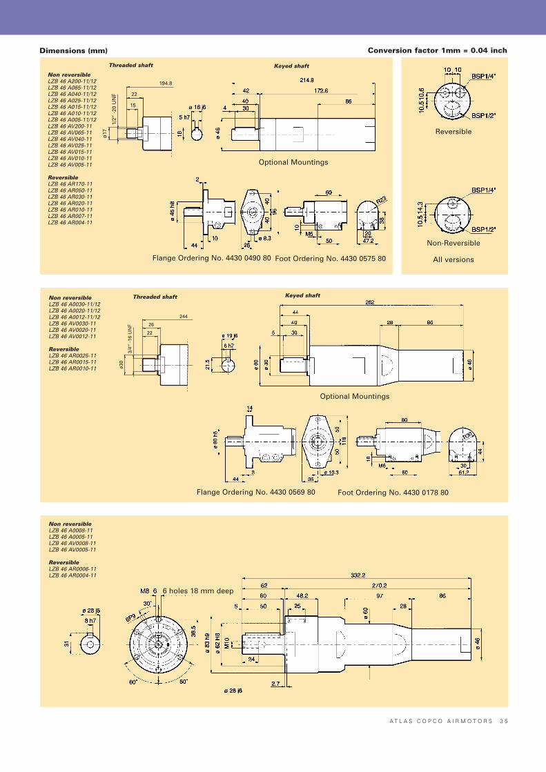
Conversion factor 1mm = 0.04 inch
Non reversibleLZB 46 A200-11/12LZB 46 A065-11/12LZB 46 A040-11/12LZB 46 A025-11/12LZB 46 A015-11/12LZB 46 A010-11/12LZB 46 A005-11/12LZB 46 AV200-11LZB 46 AV065-11LZB 46 AV040-11LZB 46 AV025-11LZB 46 AV015-11LZB 46 AV010-11LZB 46 AV005-11
ReversibleLZB 46 AR170-11LZB 46 AR050-11LZB 46 AR030-11LZB 46 AR020-11LZB 46 AR010-11LZB 46 AR007-11LZB 46 AR004-11
Non reversibleLZB 46 A0030-11/12LZB 46 A0020-11/12LZB 46 A0012-11/12LZB 46 AV0030-11LZB 46 AV0020-11LZB 46 AV0012-11
ReversibleLZB 46 AR0025-11LZB 46 AR0015-11LZB 46 AR0010-11
Non reversibleLZB 46 A0008-11LZB 46 A0005-11LZB 46 AV0008-11LZB 46 AV0005-11
ReversibleLZB 46 AR0006-11LZB 46 AR0004-11
Dimensions (mm)
Optional Mountings
Flange Ordering No. 4430 0490 80 Foot Ordering No. 4430 0575 80
Optional Mountings
Flange Ordering No. 4430 0569 80 Foot Ordering No. 4430 0178 80
6 holes 18 mm deep
Threaded shaft
Threaded shaft Keyed shaft
Keyed shaft
Non-Reversible
All versions
Reversible
194.8
22
15
1/2“
-20
UN
F
ø17
244
26
22
3/4“
-16
UN
F
ø30
3 6 A T L A S C O P C O A I R M O T O R S
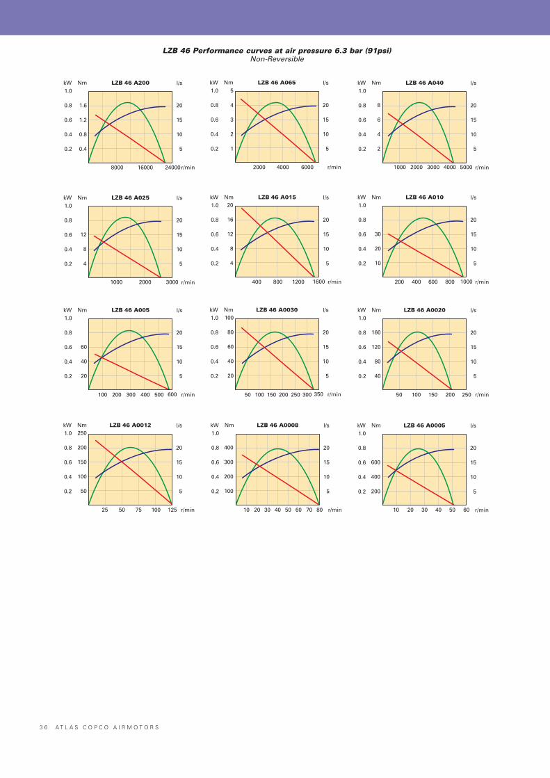
Nm LZB 46 A200 l/s
r/min
kW1.0
0.8
0.6
0.4
0.2
1.6
1.2
0.8
0.4
20
15
10
5
8000 16000 24000
Nm LZB 46 A065 l/s
r/min
kW1.0
0.8
0.6
0.4
0.2
5
4
3
2
1
20
15
10
5
2000 4000 6000
Nm LZB 46 A040 l/s
r/min
kW1.0
0.8
0.6
0.4
0.2
8
6
4
2
20
15
10
5
1000 2000 3000 4000 5000
Nm LZB 46 A025 l/s
r/min
kW1.0
0.8
0.6
0.4
0.2
12
8
4
20
15
10
5
1000 2000 3000
Nm LZB 46 A015 l/s
r/min
kW1.0
0.8
0.6
0.4
0.2
20
16
12
8
4
20
15
10
5
400 800 16001200
Nm LZB 46 A010 l/s
r/min
kW1.0
0.8
0.6
0.4
0.2
30
20
10
20
15
10
5
200 400 1000600 800
Nm LZB 46 A005 l/s
r/min
kW1.0
0.8
0.6
0.4
0.2
60
40
20
20
15
10
5
100 200 600300 400 500
Nm LZB 46 A0030 l/s
r/min
kW1.0
0.8
0.6
0.4
0.2
100
80
60
40
20
20
15
10
5
50 100 350150 200 250 300
Nm LZB 46 A0020 l/s
r/min
kW1.0
0.8
0.6
0.4
0.2
160
120
80
40
20
15
10
5
50 100 150 200 250
Nm LZB 46 A0012 l/s
r/min
kW1.0
0.8
0.6
0.4
0.2
250
200
150
100
50
20
15
10
5
25 50 75 100 125
Nm LZB 46 A0008 l/s
r/min
kW1.0
0.8
0.6
0.4
0.2
400
300
200
100
20
15
10
5
10 20 30 60 8040 50 70
Nm LZB 46 A0005 l/s
r/min
kW1.0
0.8
0.6
0.4
0.2
600
400
200
20
15
10
5
10 20 30 6040 50
LZB 46 Performance curves at air pressure 6.3 bar (91psi)Non-Reversible
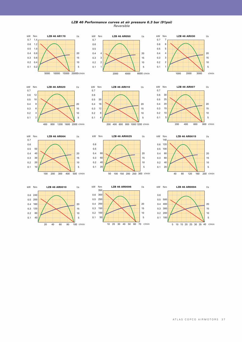
A T L A S C O P C O A I R M O T O R S 3 7
Nm LZB 46 AR170 l/s
r/min
kW0.7
0.6
0.5
0.4
0.3
0.2
0.1
1.4
1.2
1.0
0.8
0.6
0.4
0.2
20
15
10
5
5000 10000 2000015000
Nm LZB 46 AR050 l/s
r/min
kW0.7
0.6
0.5
0.4
0.3
0.2
0.1
4
3
2
1
20
15
10
5
2000 60004000
Nm LZB 46 AR030 l/s
r/min
kW0.7
0.6
0.5
0.4
0.3
0.2
0.1
7
6
5
4
3
2
1
20
15
10
5
1000 30002000
Nm LZB 46 AR020 l/s
r/min
kW0.7
0.6
0.5
0.4
0.3
0.2
0.1
12
10
8
6
4
2
20
15
10
5
400 1600800 1200 2000
Nm LZB 46 AR010 l/s
r/min
kW0.7
0.6
0.5
0.4
0.3
0.2
0.1
20
16
12
8
4
20
15
10
5
200 800400 600 12001000
Nm LZB 46 AR007 l/s
r/min
kW0.7
0.6
0.5
0.4
0.3
0.2
0.1
30
25
20
15
10
5
20
15
10
5
200 400 800600
Nm LZB 46 AR004 l/s
r/min
kW0.7
0.6
0.5
0.4
0.3
0.2
0.1
50
40
30
20
10
20
15
10
5
100 200 500300 400
Nm LZB 46 AR0025 l/s
r/min
kW
0.6
0.5
0.4
0.3
0.2
0.1
80
60
40
20
20
15
10
5
50 100 300150 200 250
Nm LZB 46 AR0015 l/s
r/min
kW
0.6
0.5
0.4
0.3
0.2
0.1
140
120
100
80
60
40
20
20
15
10
5
40 20080 120 160
Nm LZB 46 AR0010 l/s
r/min
kW
0.6
0.5
0.4
0.3
0.2
0.1
240
200
160
120
80
40
20
15
10
5
20 10040 60 80
Nm LZB 46 AR0006 l/s
r/min
kW
0.6
0.5
0.4
0.3
0.2
0.1
350
300
250
200
150
100
50
20
15
10
5
10 7020 30 5040 60
Nm LZB 46 AR0004 l/s
r/min
kW
0.6
0.5
0.4
0.3
0.2
0.1
500
400
300
200
100
20
15
10
5
5 4010 15 2520 30 35
LZB 46 Performance curves at air pressure 6.3 bar (91psi)Reversible
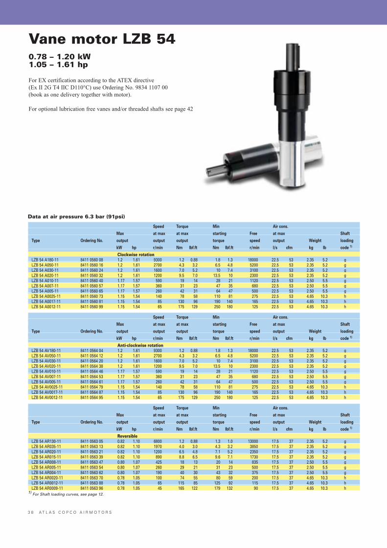
3 8 A T L A S C O P C O A I R M O T O R S
Vane motor LZB 540.78 – 1.20 kW1.05 – 1.61 hp
For EX certification according to the ATEX directive (Ex II 2G T4 IIC D110°C) use Ordering No. 9834 1107 00(book as one delivery together with motor).
For optional lubrication free vanes and/or threaded shafts see page 42
Speed Torque Min Air cons.
Max at max at max starting Free at max Shaft
Type Ordering No. output output output torque speed output Weight loading
kW hp r/min Nm lbf.ft Nm lbf.ft r/min l/s cfm kg lb code 1)
Clockwise rotationLZB 54 A180-11 8411 0560 08 1.2 1.61 9300 1.2 0.88 1.8 1.3 18000 22.5 53 2.35 5.2 gLZB 54 A050-11 8411 0560 16 1.2 1.61 2700 4.3 3.2 6.5 4.8 5200 22.5 53 2.35 5.2 gLZB 54 A030-11 8411 0560 24 1.2 1.61 1600 7.0 5.2 10 7.4 3100 22.5 53 2.35 5.2 gLZB 54 A020-11 8411 0560 32 1.2 1.61 1200 9.5 7.0 13.5 10 2300 22.5 53 2.35 5.2 gLZB 54 A010-11 8411 0560 40 1.17 1.57 590 19 14 28 21 1120 22.5 53 2.50 5.5 gLZB 54 A007-11 8411 0560 57 1.17 1.57 360 31 23 47 35 680 22.5 53 2.50 5.5 gLZB 54 A005-11 8411 0560 65 1.17 1.57 260 42 31 64 47 500 22.5 53 2.50 5.5 gLZB 54 A0025-11 8411 0560 73 1.15 1.54 140 78 58 110 81 275 22.5 53 4.65 10.3 hLZB 54 A0017-11 8411 0560 81 1.15 1.54 85 130 96 190 140 165 22.5 53 4.65 10.3 hLZB 54 A0012-11 8411 0560 99 1.15 1.54 65 175 129 250 180 125 22.5 53 4.65 10.3 h
Speed Torque Min Air cons.
Max at max at max starting Free at max Shaft
Type Ordering No. output output output torque speed output Weight loading
kW hp r/min Nm lbf.ft Nm lbf.ft r/min l/s cfm kg lb code 1)
Anti-clockwise rotationLZB 54 AV180-11 8411 0564 04 1.2 1.61 9300 1.2 0.88 1.8 1.3 18000 22.5 53 2.35 5.2 gLZB 54 AV050-11 8411 0564 12 1.2 1.61 2700 4.3 3.2 6.5 4.8 5200 22.5 53 2.35 5.2 gLZB 54 AV030-11 8411 0564 20 1.2 1.61 1600 7.0 5.2 10 7.4 3100 22.5 53 2.35 5.2 gLZB 54 AV020-11 8411 0564 38 1.2 1.61 1200 9.5 7.0 13.5 10 2300 22.5 53 2.35 5.2 gLZB 54 AV010-11 8411 0564 46 1.17 1.57 590 19 14 28 21 1120 22.5 53 2.50 5.5 gLZB 54 AV007-11 8411 0564 53 1.17 1.57 360 31 23 47 35 680 22.5 53 2.50 5.5 gLZB 54 AV005-11 8411 0564 61 1.17 1.57 260 42 31 64 47 500 22.5 53 2.50 5.5 gLZB 54 AV0025-11 8411 0564 79 1.15 1.54 140 78 58 110 81 275 22.5 53 4.65 10.3 hLZB 54 AV0017-11 8411 0564 87 1.15 1.54 85 130 96 190 140 165 22.5 53 4.65 10.3 hLZB 54 AV0012-11 8411 0564 95 1.15 1.54 65 175 129 250 180 125 22.5 53 4.65 10.3 h
Speed Torque Min Air cons.
Max at max at max starting Free at max Shaft
Type Ordering No. output output output torque speed output Weight loading
kW hp r/min Nm lbf.ft Nm lbf.ft r/min l/s cfm kg lb code 1)
ReversibleLZB 54 AR130-11 8411 0563 05 0.82 1.10 6800 1.2 0.88 1.3 1.0 13000 17.5 37 2.35 5.2 gLZB 54 AR035-11 8411 0563 13 0.82 1.10 1970 4.0 3.0 4.3 3.2 3850 17.5 37 2.35 5.2 gLZB 54 AR020-11 8411 0563 21 0.82 1.10 1200 6.5 4.8 7.1 5.2 2350 17.5 37 2.35 5.2 gLZB 54 AR015-11 8411 0563 39 0.82 1.10 890 8.8 6.5 9.6 7.1 1730 17.5 37 2.35 5.2 gLZB 54 AR008-11 8411 0563 47 0.80 1.07 425 18 13 20 14 835 17.5 37 2.50 5.5 gLZB 54 AR005-11 8411 0563 54 0.80 1.07 260 29 21 31 23 500 17.5 37 2.50 5.5 gLZB 54 AR004-11 8411 0563 62 0.80 1.07 190 40 30 43 32 375 17.5 37 2.50 5.5 gLZB 54 AR0020-11 8411 0563 70 0.78 1.05 100 74 55 80 59 200 17.5 37 4.65 10.3 hLZB 54 AR0012-11 8411 0563 88 0.78 1.05 65 115 85 125 92 115 17.5 37 4.65 10.3 hLZB 54 AR0009-11 8411 0563 96 0.78 1.05 45 165 122 179 132 90 17.5 37 4.65 10.3 h
1) For Shaft loading curves, see page 12.
Data at air pressure 6.3 bar (91psi)
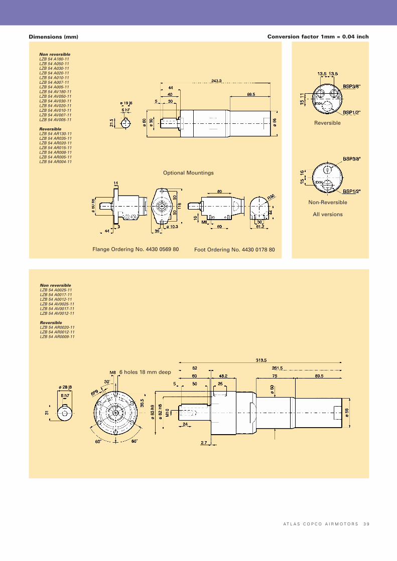
A T L A S C O P C O A I R M O T O R S 3 9
Non reversibleLZB 54 A180-11LZB 54 A050-11LZB 54 A030-11LZB 54 A020-11LZB 54 A010-11LZB 54 A007-11LZB 54 A005-11LZB 54 AV180-11LZB 54 AV050-11LZB 54 AV030-11LZB 54 AV020-11LZB 54 AV010-11LZB 54 AV007-11LZB 54 AV005-11
ReversibleLZB 54 AR130-11LZB 54 AR035-11LZB 54 AR020-11LZB 54 AR015-11LZB 54 AR008-11LZB 54 AR005-11LZB 54 AR004-11
Non reversibleLZB 54 A0025-11LZB 54 A0017-11LZB 54 A0012-11LZB 54 AV0025-11LZB 54 AV0017-11LZB 54 AV0012-11
ReversibleLZB 54 AR0020-11LZB 54 AR0012-11LZB 54 AR0009-11
Conversion factor 1mm = 0.04 inchDimensions (mm)
Optional Mountings
Flange Ordering No. 4430 0569 80 Foot Ordering No. 4430 0178 80
6 holes 18 mm deep
Reversible
Non-Reversible
All versions
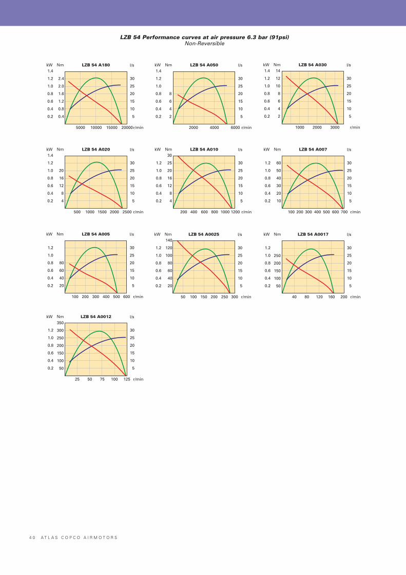
4 0 A T L A S C O P C O A I R M O T O R S
Nm LZB 54 A180 l/s
r/min
kW1.4
1.2
1.0
0.8
0.6
0.4
0.2
2.4
2.0
1.6
1.2
0.8
0.4
30
25
20
15
10
5
5000 10000 15000 20000
Nm LZB 54 A050 l/s
r/min
kW1.4
1.2
1.0
0.8
0.6
0.4
0.2
8
6
4
2
30
25
20
15
10
5
2000 4000 6000
Nm LZB 54 A030 l/s
r/min
kW1.4
1.2
1.0
0.8
0.6
0.4
0.2
14
12
10
8
6
4
2
30
25
20
15
10
5
1000 2000 3000
Nm LZB 54 A020 l/s
r/min
kW1.4
1.2
1.0
0.8
0.6
0.4
0.2
20
16
12
8
4
30
25
20
15
10
5
500 1000 20001500 2500
Nm LZB 54 A010 l/s
r/min
kW
1.2
1.0
0.8
0.6
0.4
0.2
30
25
20
16
12
8
4
30
25
20
15
10
5
200 400 800600 12001000
Nm LZB 54 A007 l/s
r/min
kW
1.2
1.0
0.8
0.6
0.4
0.2
60
50
40
30
20
10
30
25
20
15
10
5
100 200 400300 700500 600
Nm LZB 54 A005 l/s
r/min
kW
1.2
1.0
0.8
0.6
0.4
0.2
80
60
40
20
30
25
20
15
10
5
100 200 400300 500 600
Nm LZB 54 A0025 l/s
r/min
kW
1.2
1.0
0.8
0.6
0.4
0.2
140
120
100
80
60
40
20
30
25
20
15
10
5
50 100 200150 250 300
Nm LZB 54 A0017 l/s
r/min
kW
1.2
1.0
0.8
0.6
0.4
0.2
250
200
150
100
50
30
25
20
15
10
5
40 80 120 160 200
Nm LZB 54 A0012 l/s
r/min
kW
1.2
1.0
0.8
0.6
0.4
0.2
350
300
250
200
150
100
50
30
25
20
15
10
5
25 50 75 100 125
LZB 54 Performance curves at air pressure 6.3 bar (91psi)Non-Reversible
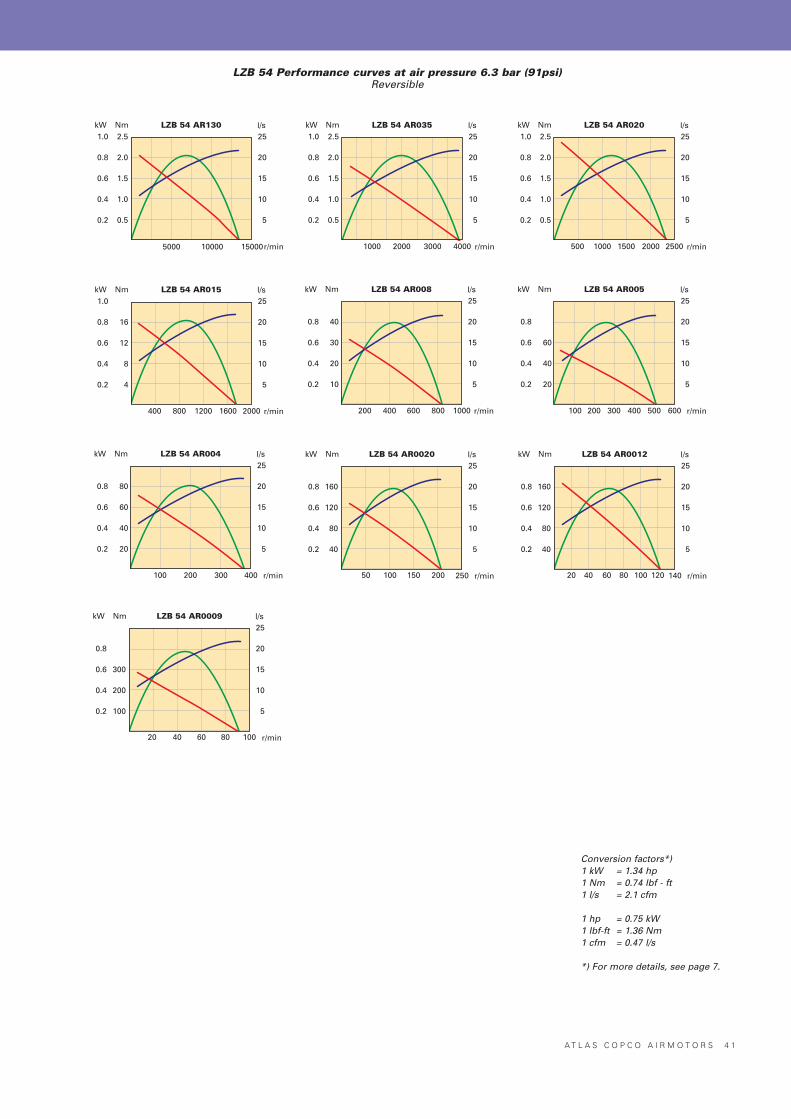
A T L A S C O P C O A I R M O T O R S 4 1
Nm LZB 54 AR130 l/s
r/min
kW1.0
0.8
0.6
0.4
0.2
2.5
2.0
1.5
1.0
0.5
25
20
15
10
5
5000 10000 15000
Nm LZB 54 AR035 l/s
r/min
kW1.0
0.8
0.6
0.4
0.2
2.5
2.0
1.5
1.0
0.5
25
20
15
10
5
1000 2000 40003000
Nm LZB 54 AR020 l/s
r/min
kW1.0
0.8
0.6
0.4
0.2
2.5
2.0
1.5
1.0
0.5
25
20
15
10
5
500 1000 25001500 2000
Nm LZB 54 AR015 l/s
r/min
kW1.0
0.8
0.6
0.4
0.2
16
12
8
4
25
20
15
10
5
400 800 20001200 1600
Nm LZB 54 AR008 l/s
r/min
kW
0.8
0.6
0.4
0.2
40
30
20
10
25
20
15
10
5
200 400 1000600 800
Nm LZB 54 AR005 l/s
r/min
kW
0.8
0.6
0.4
0.2
60
40
20
25
20
15
10
5
100 200 600300 400 500
Nm LZB 54 AR004 l/s
r/min
kW
0.8
0.6
0.4
0.2
80
60
40
20
25
20
15
10
5
100 200 300 400
Nm LZB 54 AR0020 l/s
r/min
kW
0.8
0.6
0.4
0.2
160
120
80
40
25
20
15
10
5
50 100 150 250200
Nm LZB 54 AR0012 l/s
r/min
kW
0.8
0.6
0.4
0.2
160
120
80
40
25
20
15
10
5
20 40 60 14010080 120
Nm LZB 54 AR0009 l/s
r/min
kW
0.8
0.6
0.4
0.2
300
200
100
25
20
15
10
5
20 40 60 10080
LZB 54 Performance curves at air pressure 6.3 bar (91psi)Reversible
Conversion factors*)1 kW = 1.34 hp1 Nm = 0.74 Ibf - ft1 l/s = 2.1 cfm
1 hp = 0.75 kW1 Ibf-ft = 1.36 Nm1 cfm = 0.47 l/s
*) For more details, see page 7.

Key chuck and quick chuck for LZB 22/33-12Body Capacity Ordering No.
Chuck type Mount diameter (mm) (mm)
Key chuck 3/8-24 UNF 30 0 - 6.5 4021 0283 00Key chuck 3/8-24 UNF 36 2.0 - 10.0 4021 0416 00Key chuck 3/8-24 UNF 46 2.0 - 13.0 4021 0289 00Quick chuck 3/8-24 UNF 34 0 - 6.5 4021 0401 00Quick chuck 3/8-24 UNF 36 0 - 10.0 4021 0402 00Quick chuck 3/8-24 UNF 36 2.0 - 13.0 4021 0403 00
Collet chuck and collets for LZB 22/33-12Capacity Ordering No.
mm in
Collet holder cpl. 4110 0844 90Collet 3 4150 0081 00Collet 5 4150 0075 01Collet 6 4150 0075 00Collet 8 5/16 4150 0074 00Collet 1/8 4150 0082 00Collet 5/32 4150 0648 00Collet 3/16 4150 0649 00Collet 1/4 4150 0076 00
4 2 A T L A S C O P C O A I R M O T O R S
Threaded shafts for re-building standard motorsMotor Thread dimension Ordering No.
LZB 42 A200 1/2"–20 UNF 4430 0868 80LZB 42 A065 1/2"–20 UNF 4430 0868 80LZB 42 A040 1/2"–20 UNF 4430 0868 81LZB 42 A025 1/2"–20 UNF 4430 0868 82LZB 42 A015 1/2"–20 UNF 4430 0869 80LZB 42 A010 1/2"–20 UNF 4430 0869 80LZB 42 A005 1/2"–20 UNF 4430 0869 80LZB 42 A0030 3/4"–16 UNF 4430 0870 80LZB 42 A0020 3/4"–16 UNF 4430 0870 80LZB 42 A0012 3/4"–16 UNF 4430 0870 80LZB 54 A180 1/2"–20 UNF 4430 0871 80LZB 54 A050 1/2"–20 UNF 4430 0871 80LZB 54 A030 1/2"–20 UNF 4430 0871 81LZB 54 A020 1/2"–20 UNF 4430 0871 82LZB 54 A010 3/4"–16 UNF 4430 0870 80LZB 54 A007 3/4"–16 UNF 4430 0870 80LZB 54 A005 3/4"–16 UNF 4430 0870 80
Accessories for LZB air motors
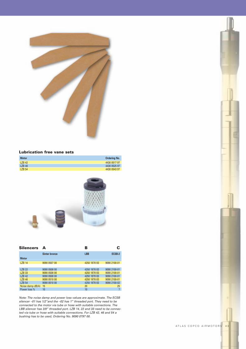
A T L A S C O P C O A I R M O T O R S 4 3
Lubrication free vane setsMotor Ordering No.
LZB 42 4430 0517 97LZB 46 4430 0525 97LZB 54 4430 0543 97
Silencers A B CSinter bronze LBB ECSB-2
Motor
LZB 14 9090 0507 00 4250 1878 83 9090 2100-01
LZB 22 9090 0508 00 4250 1878 83 9090 2100-01LZB 33 9090 0508 00 4250 1878 83 9090 2100-01LZB 42 9090 0508 00 4250 1878 83 9090 2100-01LZB 46 9090 0510 00 4250 1878 83 9090 2100-01LZB 54 9090 0510 00 4250 1878 83 9090 2100-02Noise damp dB(A) 15 20 25Power loss % 10 10 7
Note: The noise damp and power loss values are approximate. The ECSBsilencer –01 has 1/2”and the –02 has 1” threaded port. They need to beconnected to the motor via tube or hose with suitable connections. TheLBB silencer has 3/8” threaded port. LZB 14, 22 and 33 need to be connec-ted via tube or hose with suitable connections. For LZB 42, 46 and 54 abushing has to be used, Ordering No. 9090 0797 00.
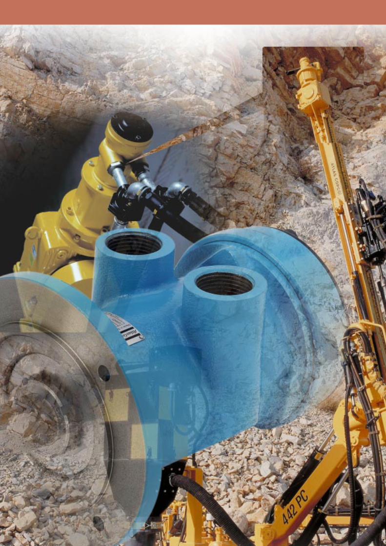
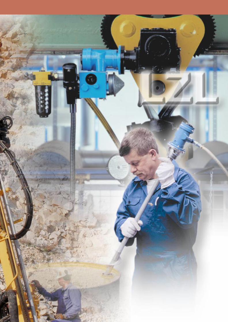
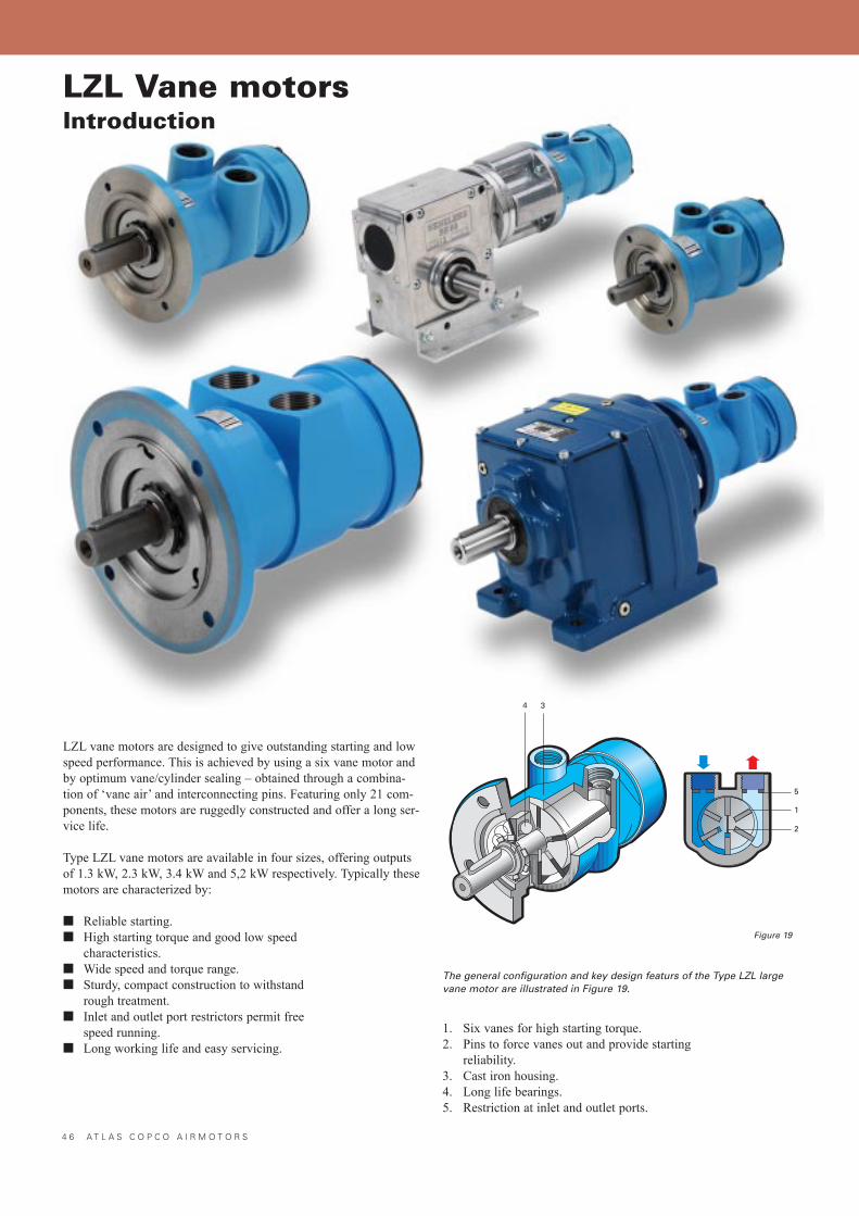
4 6 A T L A S C O P C O A I R M O T O R S
LZL vane motors are designed to give outstanding starting and lowspeed performance. This is achieved by using a six vane motor andby optimum vane/cylinder sealing � obtained through a combina-tion of �vane air� and interconnecting pins. Featuring only 21 com-ponents, these motors are ruggedly constructed and offer a long ser-vice life.
Type LZL vane motors are available in four sizes, offering outputsof 1.3 kW, 2.3 kW, 3.4 kW and 5,2 kW respectively. Typically thesemotors are characterized by:
■ Reliable starting.■ High starting torque and good low speed
characteristics.■ Wide speed and torque range.■ Sturdy, compact construction to withstand
rough treatment.■ Inlet and outlet port restrictors permit free
speed running.■ Long working life and easy servicing.
1. Six vanes for high starting torque.2. Pins to force vanes out and provide starting
reliability.3. Cast iron housing.4. Long life bearings.5. Restriction at inlet and outlet ports.
LZL Vane motorsIntroduction
The general configuration and key design featurs of the Type LZL largevane motor are illustrated in Figure 19.
Figure 19
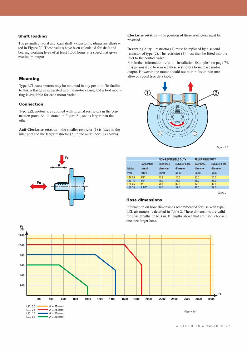
A T L A S C O P C O A I R M O T O R S 4 7
Shaft loading
The permitted radial and axial shaft extension loadings are illustra-ted in Figure 20. These values have been calculated for shaft andbearing working lives of at least 1,000 hours at a speed that givesmaximum output.
Clockwise rotation � the position of these restrictors must bereversed.
Reversing duty � restrictor (1) must be replaced by a secondrestrictor of type (2). The restrictor (1) must then be fitted into theinlet to the control valve.For further information refer to �Installation Examples� on page 74.It is permissable to remove these restrictors to increase motor output. However, the motor should not be run faster than max allowed speed (see data table).
Mounting
Type LZL vane motors may be mounted in any position. To facilita-te this, a flange is integrated into the motor casing and a foot moun-ting is available for each motor variant.
Connection
Type LZL motors are supplied with internal restrictors in the con-nection ports. As illustrated in Figure 21, one is larger than theother.
Anti-Clockwise rotation � the smaller restrictor (1) is fitted in theinlet port and the larger restrictor (2) in the outlet port (as shown).
Fr
1200
1000
800
600
400
200
200012001000800600400200
Fa(N)
1400 1600 1800
LZL 35LZL 25LZL 15LZL 05
A = 25 mmA = 25 mmA = 25 mmA = 20 mm
30002200 2400 2600 2800
NON-REVERSIBLE DUTY REVERSIBLE DUTY
Connection Inlet hose Exhaust hose Inlet hose Exhaust hose
Motor thread diameter dimaeter diameter diameter
type (BSP) (mm) (mm) (mm) (mm)
LZL 05 1/2" 12.5 20.0 20.0 20.0LZL 15 3/4" 16.0 25.0 25.0 25.0LZL 25 1" 20.0 32.0 32.0 32.0LZL 35 1 1/4" 20.0 32.0 32.0 32.0
Figure 20
Figure 21
Table 2
Hose dimensions
Information on hose dimensions recommended for use with typeLZL air motors is detailed in Table 2. These dimensions are validfor hose lengths up to 3 m. If lengths above that are used, choose aone size larger hose.
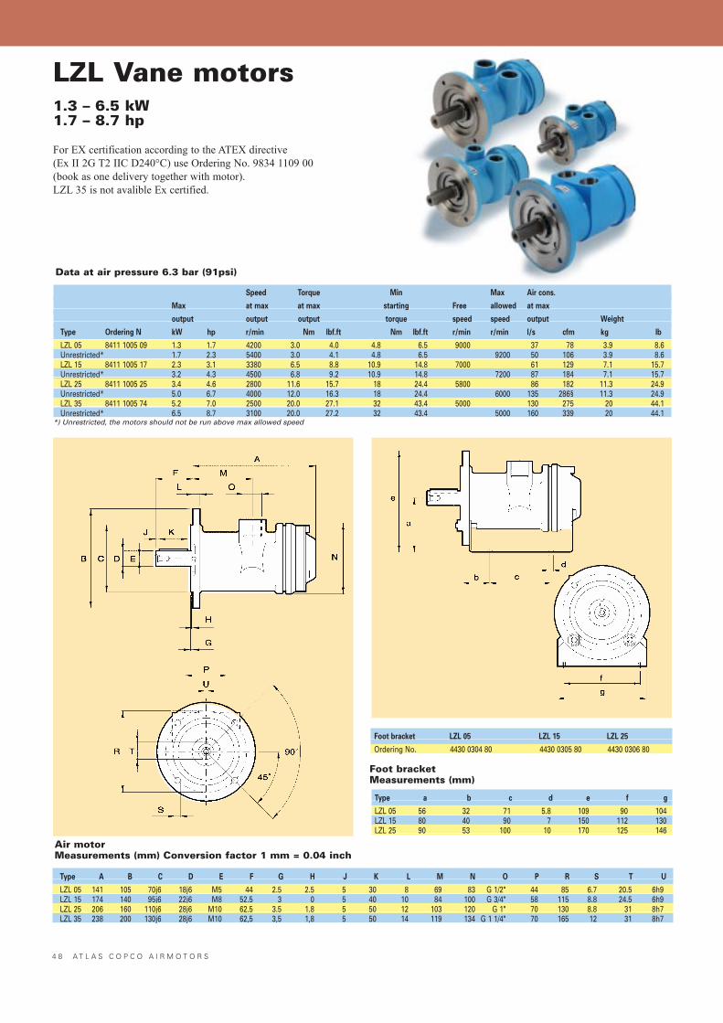
4 8 A T L A S C O P C O A I R M O T O R S
LZL Vane motors1.3 – 6.5 kW1.7 – 8.7 hp
For EX certification according to the ATEX directive (Ex II 2G T2 IIC D240°C) use Ordering No. 9834 1109 00(book as one delivery together with motor).LZL 35 is not avalible Ex certified.
Speed Torque Min Max Air cons.
Max at max at max starting Free allowed at max
output output output torque speed speed output Weight
Type Ordering N kW hp r/min Nm lbf.ft Nm lbf.ft r/min r/min l/s cfm kg lb
LZL 05 8411 1005 09 1.3 1.7 4200 3.0 4.0 4.8 6.5 9000 37 78 3.9 8.6Unrestricted* 1.7 2.3 5400 3.0 4.1 4.8 6.5 9200 50 106 3.9 8.6LZL 15 8411 1005 17 2.3 3.1 3380 6.5 8.8 10.9 14.8 7000 61 129 7.1 15.7Unrestricted* 3.2 4.3 4500 6.8 9.2 10.9 14.8 7200 87 184 7.1 15.7LZL 25 8411 1005 25 3.4 4.6 2800 11.6 15.7 18 24.4 5800 86 182 11.3 24.9Unrestricted* 5.0 6.7 4000 12.0 16.3 18 24.4 6000 135 286§ 11.3 24.9LZL 35 8411 1005 74 5.2 7.0 2500 20.0 27.1 32 43.4 5000 130 275 20 44.1Unrestricted* 6.5 8.7 3100 20.0 27.2 32 43.4 5000 160 339 20 44.1
*) Unrestricted, the motors should not be run above max allowed speed
Type A B C D E F G H J K L M N O P R S T U
LZL 05 141 105 70j6 18j6 M5 44 2.5 2.5 5 30 8 69 83 G 1/2" 44 85 6.7 20.5 6h9LZL 15 174 140 95j6 22j6 M8 52.5 3 0 5 40 10 84 100 G 3/4" 58 115 8.8 24.5 6h9LZL 25 206 160 110j6 28j6 M10 62.5 3.5 1.8 5 50 12 103 120 G 1" 70 130 8.8 31 8h7LZL 35 238 200 130j6 28j6 M10 62,5 3,5 1,8 5 50 14 119 134 G 1 1/4" 70 165 12 31 8h7
Foot bracket LZL 05 LZL 15 LZL 25
Ordering No. 4430 0304 80 4430 0305 80 4430 0306 80
Type a b c d e f g
LZL 05 56 32 71 5.8 109 90 104LZL 15 80 40 90 7 150 112 130LZL 25 90 53 100 10 170 125 146
Foot bracketMeasurements (mm)
Air motorMeasurements (mm) Conversion factor 1 mm = 0.04 inch
Data at air pressure 6.3 bar (91psi)
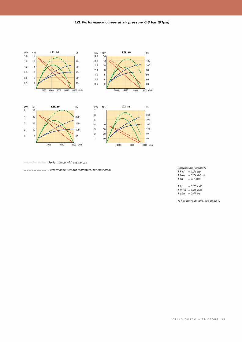
A T L A S C O P C O A I R M O T O R S 4 9
LZL 05
2000 4000 6000 8000 10000 r/min
15
30
45
60
75
l/s
0.3
0.6
0.9
1.2
1.5
1.8kW
1
2
3
4
5
6Nm LZL 15
2000 4000 6000 8000 r/min
20
40
60
80
100
120
l/s
0.5
1.0
1.5
2.0
2.5
3.0
3.5kW
2
4
6
8
10
12
14Nm
LZL 25
2000 4000 6000 r/min
50
100
150
200
l/s
1
2
3
4
5kW
5
10
15
20
25Nm LZL 35
2000 4000 6000 r/min
40
80
120
160
200
240
l/s
1
2
3
4
5
6
7kW
10
20
30
40
Nm
Conversion Factors*)1 kW = 1.34 hp1 Nm = 0.74 Ibf - ft1 l/s = 2.1 cfm
1 hp = 0.75 kW1 Ibf-ft = 1.36 Nm1 cfm = 0.47 l/s
*) For more details, see page 7.
LZL Performance curves at air pressure 6.3 bar (91psi)
Performance with restrictors
Performance without restrictors, (unrestricted)
–––––---------
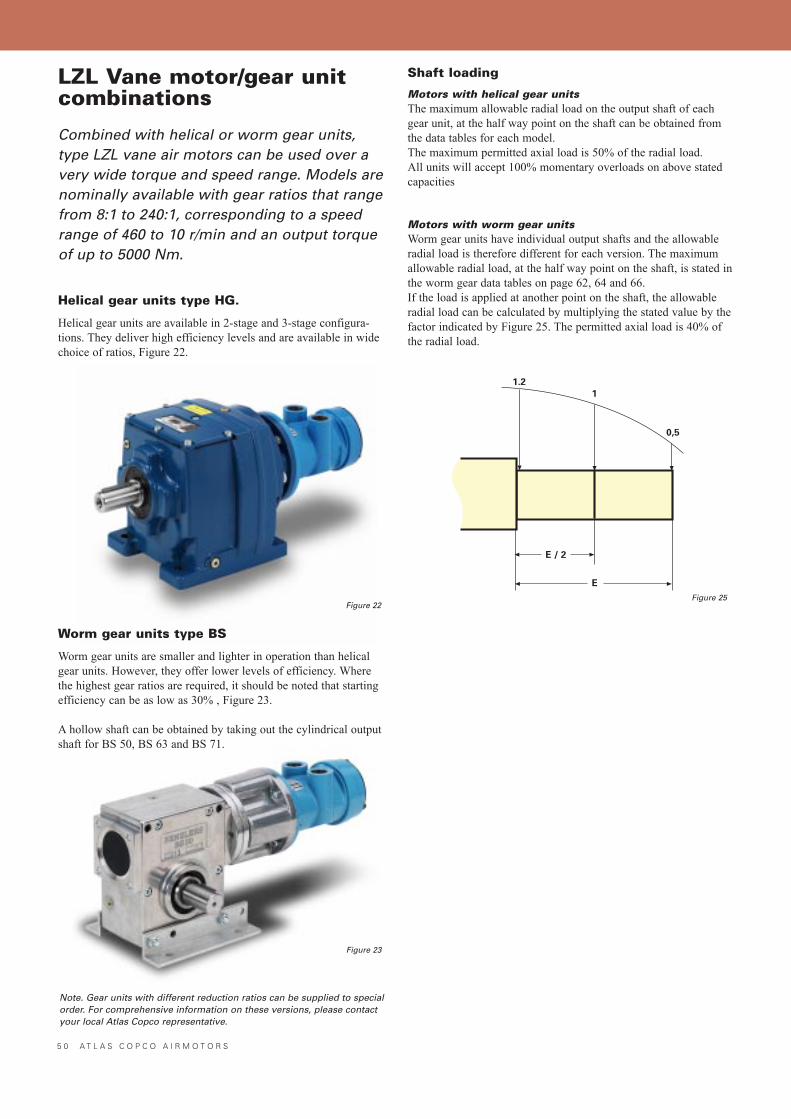
5 0 A T L A S C O P C O A I R M O T O R S
LZL Vane motor/gear unitcombinations
Combined with helical or worm gear units,type LZL vane air motors can be used over avery wide torque and speed range. Models arenominally available with gear ratios that rangefrom 8:1 to 240:1, corresponding to a speedrange of 460 to 10 r/min and an output torqueof up to 5000 Nm.
Helical gear units type HG.
Helical gear units are available in 2-stage and 3-stage configura-tions. They deliver high efficiency levels and are available in widechoice of ratios, Figure 22.
Worm gear units type BS
Worm gear units are smaller and lighter in operation than helicalgear units. However, they offer lower levels of efficiency. Wherethe highest gear ratios are required, it should be noted that startingefficiency can be as low as 30% , Figure 23.
A hollow shaft can be obtained by taking out the cylindrical outputshaft for BS 50, BS 63 and BS 71.
Shaft loading
Motors with helical gear unitsThe maximum allowable radial load on the output shaft of eachgear unit, at the half way point on the shaft can be obtained fromthe data tables for each model.The maximum permitted axial load is 50% of the radial load.All units will accept 100% momentary overloads on above statedcapacities
Motors with worm gear unitsWorm gear units have individual output shafts and the allowableradial load is therefore different for each version. The maximumallowable radial load, at the half way point on the shaft, is stated inthe worm gear data tables on page 62, 64 and 66.If the load is applied at another point on the shaft, the allowableradial load can be calculated by multiplying the stated value by thefactor indicated by Figure 25. The permitted axial load is 40% ofthe radial load.
Figure 22
Figure 23
1.2
1
0,5
E / 2
E
Note. Gear units with different reduction ratios can be supplied to specialorder. For comprehensive information on these versions, please contactyour local Atlas Copco representative.
Figure 25
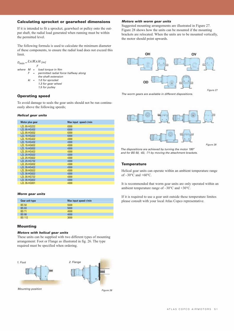
A T L A S C O P C O A I R M O T O R S 5 1
Calculating sprocket or gearwheel dimensions
If it is intended to fit a sprocket, gearwheel or pulley onto the out-put shaft, the radial load generated when running must be withinthe permitted level.
The following formula is used to calculate the minimum diameterof these components, to ensure the radial load does not exceed thislimit.
Dmin = 2 x M x kt [m]F
where M = load torque in NmF = permitted radial force halfway along
the shaft extensionkt = 1.0 for sprocket
1.3 for gear wheel1.5 for pulley
Operating speed
To avoid damage to seals the gear units should not be run continu-ously above the following speeds;
Helical gear units
Motor plus gear Max input speed r/min
LZL 05-HG222 6300LZL 05-HG432 6300LZL 05-HG632 6300LZL 15-HG222 6300LZL 15-HG422 4300LZL 15-HG432 4300LZL 15-HG632 4300LZL 15-HG832 4300LZL 25-HG422 4300LZL 25-HG522 4300LZL 25-HG622 4300LZL 25-HG732 4300LZL 25-HG832 4300LZL 35-HG422 4300LZL 35-HG522 4300LZL 35-HG622 4300LZL 35-HG722 4300LZL 35-HG822 4300LZL 35-HG931 4300
Worm gear units
Gear unit type Max input speed r/min
BS 50 5500BS 63 5000BS 71 4500BS 88 4000BS 112 3000
Mounting
Motors with helical gear unitsThese units can be supplied with two different types of mountingarrangement: Foot or Flange as illustrated in fig. 26. The typerequired must be specified when ordering.
Figure 26
1. Foot
Mounting position
2. Flange
Motors with worm gear unitsSuggested mounting arrangements are illustrated in Figure 27.Figure 28 shows how the units can be mounted if the mountingbrackets are relocated. When the units are to be mounted vertically,the motor should point upwards.
Temperature
Helical gear units can operate within an ambient temperature rangeof �30°C and +60°C.
It is recommended that worm gear units are only operated within anambient temperature range of �30°C and +30°C.
If it is required to use a gear unit outside these temperature limitesplease consult with your local Atlas Copco representative.
Figure 27
The worm gears are available in different dispositions.
The dispositions are achieved by turning the motor 180°and for BS 50, -63, -71 by moving the attachment brackets.
Figure 28
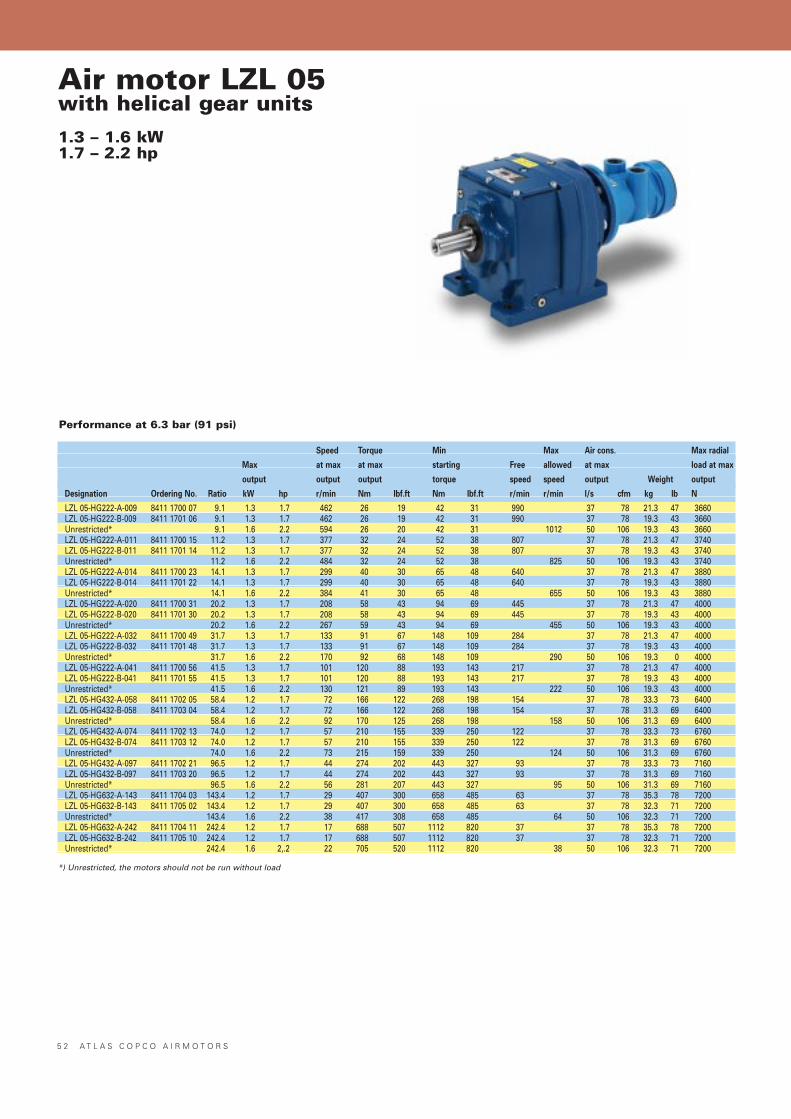
Air motor LZL 05with helical gear units1.3 – 1.6 kW1.7 – 2.2 hp
Performance at 6.3 bar (91 psi)
Speed Torque Min Max Air cons. Max radial
Max at max at max starting Free allowed at max load at max
output output output torque speed speed output Weight output
Designation Ordering No. Ratio kW hp r/min Nm lbf.ft Nm lbf.ft r/min r/min l/s cfm kg lb N
LZL 05-HG222-A-009 8411 1700 07 9.1 1.3 1.7 462 26 19 42 31 990 37 78 21.3 47 3660LZL 05-HG222-B-009 8411 1701 06 9.1 1.3 1.7 462 26 19 42 31 990 37 78 19.3 43 3660Unrestricted* 9.1 1.6 2.2 594 26 20 42 31 1012 50 106 19.3 43 3660LZL 05-HG222-A-011 8411 1700 15 11.2 1.3 1.7 377 32 24 52 38 807 37 78 21.3 47 3740LZL 05-HG222-B-011 8411 1701 14 11.2 1.3 1.7 377 32 24 52 38 807 37 78 19.3 43 3740Unrestricted* 11.2 1.6 2.2 484 32 24 52 38 825 50 106 19.3 43 3740LZL 05-HG222-A-014 8411 1700 23 14.1 1.3 1.7 299 40 30 65 48 640 37 78 21.3 47 3880LZL 05-HG222-B-014 8411 1701 22 14.1 1.3 1.7 299 40 30 65 48 640 37 78 19.3 43 3880Unrestricted* 14.1 1.6 2.2 384 41 30 65 48 655 50 106 19.3 43 3880LZL 05-HG222-A-020 8411 1700 31 20.2 1.3 1.7 208 58 43 94 69 445 37 78 21.3 47 4000LZL 05-HG222-B-020 8411 1701 30 20.2 1.3 1.7 208 58 43 94 69 445 37 78 19.3 43 4000Unrestricted* 20.2 1.6 2.2 267 59 43 94 69 455 50 106 19.3 43 4000LZL 05-HG222-A-032 8411 1700 49 31.7 1.3 1.7 133 91 67 148 109 284 37 78 21.3 47 4000LZL 05-HG222-B-032 8411 1701 48 31.7 1.3 1.7 133 91 67 148 109 284 37 78 19.3 43 4000Unrestricted* 31.7 1.6 2.2 170 92 68 148 109 290 50 106 19.3 0 4000LZL 05-HG222-A-041 8411 1700 56 41.5 1.3 1.7 101 120 88 193 143 217 37 78 21.3 47 4000LZL 05-HG222-B-041 8411 1701 55 41.5 1.3 1.7 101 120 88 193 143 217 37 78 19.3 43 4000Unrestricted* 41.5 1.6 2.2 130 121 89 193 143 222 50 106 19.3 43 4000LZL 05-HG432-A-058 8411 1702 05 58.4 1.2 1.7 72 166 122 268 198 154 37 78 33.3 73 6400LZL 05-HG432-B-058 8411 1703 04 58.4 1.2 1.7 72 166 122 268 198 154 37 78 31.3 69 6400Unrestricted* 58.4 1.6 2.2 92 170 125 268 198 158 50 106 31.3 69 6400LZL 05-HG432-A-074 8411 1702 13 74.0 1.2 1.7 57 210 155 339 250 122 37 78 33.3 73 6760LZL 05-HG432-B-074 8411 1703 12 74.0 1.2 1.7 57 210 155 339 250 122 37 78 31.3 69 6760Unrestricted* 74.0 1.6 2.2 73 215 159 339 250 124 50 106 31.3 69 6760LZL 05-HG432-A-097 8411 1702 21 96.5 1.2 1.7 44 274 202 443 327 93 37 78 33.3 73 7160LZL 05-HG432-B-097 8411 1703 20 96.5 1.2 1.7 44 274 202 443 327 93 37 78 31.3 69 7160Unrestricted* 96.5 1.6 2.2 56 281 207 443 327 95 50 106 31.3 69 7160LZL 05-HG632-A-143 8411 1704 03 143.4 1.2 1.7 29 407 300 658 485 63 37 78 35.3 78 7200LZL 05-HG632-B-143 8411 1705 02 143.4 1.2 1.7 29 407 300 658 485 63 37 78 32.3 71 7200Unrestricted* 143.4 1.6 2.2 38 417 308 658 485 64 50 106 32.3 71 7200LZL 05-HG632-A-242 8411 1704 11 242.4 1.2 1.7 17 688 507 1112 820 37 37 78 35.3 78 7200LZL 05-HG632-B-242 8411 1705 10 242.4 1.2 1.7 17 688 507 1112 820 37 37 78 32.3 71 7200Unrestricted* 242.4 1.6 2,.2 22 705 520 1112 820 38 50 106 32.3 71 7200
*) Unrestricted, the motors should not be run without load
5 2 A T L A S C O P C O A I R M O T O R S
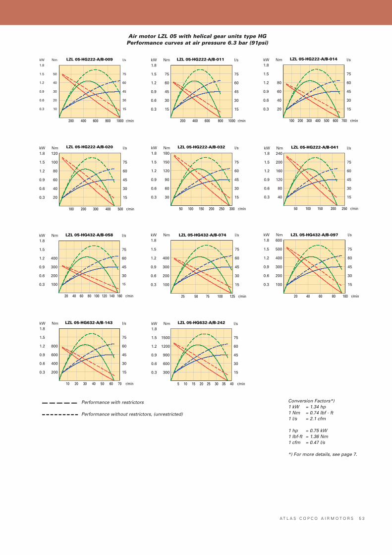
LZL 05-HG222-A/B-009
200 400 600 800 1000 r/min
15
30
45
60
75
l/s
0.3
0.6
0.9
1.2
1.5
1.8
kW
10
20
30
40
50
Nm LZL 05-HG222-A/B-014
100 200 300 400 500 600 700 r/min
15
30
45
60
75
l/s
0.3
0.6
0.9
1.2
1.5
1.8kW
20
40
60
80
Nm
LZL 05-HG222-A/B-020
100 200 300 400 500 r/min
15
30
45
60
75
l/s
0.3
0.6
0.9
1.2
1.5
1.8kW
20
40
60
80
100
120Nm LZL 05-HG222-A/B-032
50 100 150 200 250 300 r/min
15
30
45
60
75
l/s
0.3
0.6
0.9
1.2
1.5
1.8kW
30
60
90
120
150
180Nm
LZL 05-HG222-A/B-011
200 400 600 800 1000 r/min
15
30
45
60
75
l/s
0.3
0.6
0.9
1.2
1.5
1.8kW
15
30
45
60
75
Nm
LZL 05-HG222-A/B-041
50 100 150 200 250 r/min
15
30
45
60
75
l/s
0.3
0.6
0.9
1.2
1.5
1.8kW
40
80
120
160
200
240Nm
LZL 05-HG432-A/B-058
20 40 60 80 100 120 140 160 r/min
15
30
45
60
75
l/s
0.3
0.6
0.9
1.2
1.5
1.8kW
100
200
300
400
Nm LZL 05-HG432-A/B-074
25 50 75 100 125 r/min
15
30
45
60
75
l/s
0.3
0.6
0.9
1.2
1.5
1.8kW
100
200
300
400
Nm LZL 05-HG432-A/B-097
20 40 60 80 100 r/min
15
30
45
60
75
l/s
0.3
0.6
0.9
1.2
1.5
1.8kW
100
200
300
400
500
600Nm
LZL 05-HG632-A/B-143
15
30
45
60
75
l/s
0.3
0.6
0.9
1.2
1.5
1.8kW
200
400
600
800
Nm
10 20 30 40 50 60 70 r/min
LZL 05-HG632-A/B-242
5 10 15 20 25 30 35 40 r/min
15
30
45
60
75
l/s
0.3
0.6
0.9
1.2
1.5
1.8kW
300
600
900
1200
1500
Nm
Conversion Factors*)1 kW = 1.34 hp1 Nm = 0.74 Ibf - ft1 l/s = 2.1 cfm
1 hp = 0.75 kW1 Ibf-ft = 1.36 Nm1 cfm = 0.47 l/s
*) For more details, see page 7.
Air motor LZL 05 with helical gear units type HGPerformance curves at air pressure 6.3 bar (91psi)
A T L A S C O P C O A I R M O T O R S 5 3
Performance with restrictors
Performance without restrictors, (unrestricted)
–––––---------
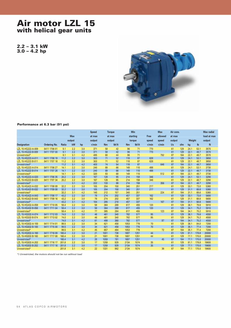
5 4 A T L A S C O P C O A I R M O T O R S
Air motor LZL 15with helical gear units
2.2 – 3.1 kW3.0 – 4.2 hp
Performance at 6.3 bar (91 psi)
Speed Torque Min Max Air cons. Max radial
Max at max at max starting Free allowed at max load at max
output output output torque speed speed output Weight output
Designation Ordering No. Ratio kW hp r/min Nm lbf.ft Nm lbf.ft r/min r/min l/s cfm kg lb N
LZL 15-HG222-A-009 8411 1706 01 9.1 2.2 3.0 371 58 42 96 71 770 61 129 24.1 53.1 3570LZL 15-HG222-B-009 8411 1707 00 9.1 2.2 3.0 371 58 42 96 71 770 61 129 22.1 48.7 3570Unrestricted* 9.1 3.1 4.2 495 60 44 96 71 792 87 184 22.1 48.7 3570LZL 15-HG222-A-011 8411 1706 19 11.2 2.2 3.0 303 71 52 118 87 628 61 129 24.1 53.1 3650LZL 15-HG222-B-011 8411 1707 18 11.2 2.2 3.0 303 71 52 118 87 628 61 129 22.1 48.7 3650Unrestricted* 11.2 3.1 4.2 403 74 54 118 87 646 87 184 22.1 48.7 3650LZL 15-HG222-A-014 8411 1706 27 14.1 2.2 3.0 240 89 66 149 110 498 61 129 24.1 53.1 3730LZL 15-HG222-B-014 8411 1707 26 14.1 2.2 3.0 240 89 66 149 110 498 61 129 22.1 48.7 3730Unrestricted* 14.1 3.1 4.2 320 93 68 149 110 512 87 184 22.1 48.7 3730LZL 15-HG222-A-020 8411 1706 35 20.2 2.2 3.0 167 128 95 214 158 346 61 129 24.1 53.1 3290LZL 15-HG222-B-020 8411 1707 34 20.2 2.2 3.0 167 128 95 214 158 346 61 129 22.1 48.7 3290Unrestricted* 3.1 4.2 222 133 98 214 158 356 87 184 22.1 48.7 3290LZL 15-HG422-A-032 8411 1708 09 32.2 2.2 3.0 105 204 150 340 251 217 61 129 33.1 73.0 5360LZL 15-HG422-B-032 8411 1709 08 32.2 2.2 3.0 105 204 150 340 251 217 61 129 31.1 68.6 5360Unrestricted* 32.2 3.1 4.2 140 212 157 340 251 224 87 184 31.1 68.6 5360LZL 15-HG422-A-043 8411 1708 17 43.2 2.2 3.0 78 274 202 457 337 162 61 129 33.1 73.0 5600LZL 15-HG422-B-043 8411 1709 16 43.2 2.2 3.0 78 274 202 457 337 162 61 129 31.1 68.6 5600Unrestricted* 43.2 3.1 4.2 104 285 210 457 337 167 87 184 31.1 68.6 5600LZL 15-HG432-A-058 8411 1710 05 58.4 2.2 3.0 58 364 269 617 455 120 61 129 36.1 79.6 5910LZL 15-HG432-B-058 8411 1711 04 58.4 2.2 3.0 58 364 269 617 455 120 61 129 34.1 75.2 5910Unrestricted* 58.4 3.1 4.2 77 385 284 617 455 123 87 184 34.1 75.2 5910LZL 15-HG532-A-074 8411 1712 03 74.0 2.2 3.0 46 461 340 782 577 95 61 129 36.1 79.6 4550LZL 15-HG532-B-074 8411 1713 02 74.0 2.2 3.0 46 461 340 782 577 95 61 129 34.1 75.2 4550Unrestricted* 74.0 3.1 4.2 61 488 360 782 577 97 87 184 34.1 75.2 4550LZL 15-HG632-A-100 8411 1714 01 99.5 2.2 3.0 34 621 458 1053 776 70 61 129 38.1 84.0 7200LZL 15-HG632-B-100 8411 1715 00 99.5 2.2 3.0 34 621 458 1053 776 70 61 129 35.1 77.4 7200Unrestricted* 99.5 3.1 4.2 45 657 484 1053 776 72 87 184 35.1 77.4 7200LZL 15-HG832-A-160 8411 1716 09 160.4 2.2 3.0 21 1001 738 1697 1251 44 61 129 81.1 178.8 20000LZL 15-HG832-B-160 8411 1717 08 160.4 2.2 3.0 21 1001 738 1697 1251 44 61 129 77.1 170.0 20000Unrestricted* 160.4 3.1 4.2 28 1059 781 1697 1251 45 87 184 77.1 170.0 20000LZL 15-HG832-A-202 8411 1716 17 201.8 2.2 3.0 17 1259 929 2134 1574 35 61 129 81.1 178.8 19600LZL 15-HG832-B-202 8411 1717 16 201.8 2.2 3.0 17 1259 929 2134 1574 35 61 129 77.1 170.0 19600Unrestricted* 201.8 3.1 4.2 22 1331 982 2134 1574 36 87 184 77.1 170.0 19600
*) Unrestricted, the motors should not be run without load

A T L A S C O P C O A I R M O T O R S 5 5
LZL 15-HG222-A/B-009
200 400 600 800 r/min
20
40
60
80
100
120
l/s
0.5
1.0
1.5
2.0
2.5
3.0
3.5kW
20
40
60
80
100
120
Nm LZL 15-HG222-A/B-011
100 200 300 400 500 600 700 r/min
20
40
60
80
100
120
l/s
0.5
1.0
1.5
2.0
2.5
3.0
3.5kW
20
40
60
80
100
120
140Nm LZL 15-HG222-A/B-014
100 200 300 400 500 600 r/min
20
40
60
80
100
120
l/s
0.5
1.0
1.5
2.0
2.5
3.0
3.5kW
30
60
90
120
150
180
Nm
LZL 15-HG422-A/B-032
50 100 150 200 250 r/min
20
40
60
80
100
120
l/s
0.5
1.0
1.5
2.0
2.5
3.0
3.5kW
100
200
300
400
Nm LZL 15-HG422-A/B-043
40 80 120 160 200 r/min
20
40
60
80
100
120
l/s
0.5
1.0
1.5
2.0
2.5
3.0
3.5kW
100
200
300
400
500
600
NmLZL 15-HG222-A/B-020
100 200 300 400 r/min
20
40
60
80
100
120
l/s
0.5
1.0
1.5
2.0
2.5
3.0
3.5kW
50
100
150
200
250
Nm
LZL 15-HG432-A/B-058
25 50 75 100 125 r/min
20
40
60
80
100
120
l/s
0.5
1.0
1.5
2.0
2.5
3.0
3.5kW
100
200
300
400
500
600
700Nm LZL 15-HG532-A/B-074
20 40 60 80 100 r/min
20
40
60
80
100
120
l/s
0.5
1.0
1.5
2.0
2.5
3.0
3.5kW
150
300
450
600
750
900
Nm LZL 15-HG632-A/B-100
1020 3040 5060 7080 r/min
20
40
60
80
100
120
l/s
0.5
1.0
1.5
2.0
2.5
3.0
3.5kW
300
600
900
1200
Nm
LZL 15-HG832-A/B-160
10 20 30 40 50 r/min
20
40
60
80
100
120
l/s
0.5
1.0
1.5
2.0
2.5
3.0
3.5kW
400
800
1200
1600
2000
Nm LZL 15-HG832-A/B-202
5 10 15 20 25 30 35 40 r/min
20
40
60
80
100
120
l/s
0.5
1.0
1.5
2.0
2.5
3.0
3.5kW
400
800
1200
1600
2000
2400
Nm
Conversion Factors*)1 kW = 1.34 hp1 Nm = 0.74 Ibf - ft1 l/s = 2.1 cfm
1 hp = 0.75 kW1 Ibf-ft = 1.36 Nm1 cfm = 0.47 l/s
*) For more details, see page 7.
Air motor LZL 15 with helical gear units type HGPerformance curves at air pressure 6.3 bar (91psi)
Performance with restrictors
Performance without restrictors, (unrestricted)
–––––---------
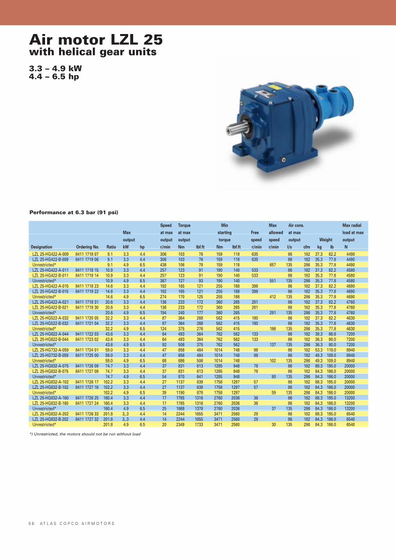
5 6 A T L A S C O P C O A I R M O T O R S
Air motor LZL 25with helical gear units3.3 – 4.9 kW4.4 – 6.5 hp
Performance at 6.3 bar (91 psi)
Speed Torque Min Max Air cons. Max radial
Max at max at max starting Free allowed at max load at max
output output output torque speed speed output Weight output
Designation Ordering No. Ratio kW hp r/min Nm lbf.ft Nm lbf.ft r/min r/min l/s cfm kg lb N
LZL 25-HG422-A-009 8411 1718 07 9.1 3.3 4.4 306 103 76 159 118 635 86 182 37.3 82.2 4490LZL 25-HG422-B-009 8411 1719 06 9.1 3.3 4.4 306 103 76 159 118 635 86 182 35.3 77.8 4490Unrestricted* 9.1 4.9 6.5 438 106 78 159 118 657 135 286 35.3 77.8 4490LZL 25-HG422-A-011 8411 1718 15 10.9 3.3 4.4 257 123 91 190 140 533 86 182 37.3 82.2 4580LZL 25-HG422-B-011 8411 1719 14 10.9 3.3 4.4 257 123 91 190 140 533 86 182 35.3 77.8 4580Unrestricted* 10.9 4.9 6.5 367 127 93 190 140 551 135 286 35.3 77.8 4580LZL 25-HG422-A-015 8411 1718 23 14.6 3.3 4.4 192 165 121 255 188 398 86 182 37.3 82.2 4690LZL 25-HG422-B-015 8411 1719 22 14.6 3.3 4.4 192 165 121 255 188 398 86 182 35.3 77.8 4690Unrestricted* 14.6 4.9 6.5 274 170 125 255 188 412 135 286 35.3 77.8 4690LZL 25-HG422-A-021 8411 1718 31 20.6 3.3 4.4 136 233 172 360 265 281 86 182 37.3 82.2 4760LZL 25-HG422-B-021 8411 1719 30 20.6 3.3 4.4 136 233 172 360 265 281 86 182 35.3 77.8 4760Unrestricted* 20.6 4.9 6.5 194 240 177 360 265 291 135 286 35.3 77.8 4760LZL 25-HG522-A-032 8411 1720 05 32.2 3.3 4.4 87 364 268 562 415 180 86 182 37.3 82.2 4630LZL 25-HG522-B-032 8411 1721 04 32.2 3.3 4.4 87 364 268 562 415 180 86 182 35.3 77.8 4630Unrestricted* 32.2 4.9 6.5 124 375 276 562 415 186 135 286 35.3 77.8 4630LZL 25-HG622-A-044 8411 1722 03 43.6 3.3 4.4 64 493 364 762 562 133 86 182 39.3 86.6 7200LZL 25-HG622-B-044 8411 1723 02 43.6 3.3 4.4 64 493 364 762 562 133 86 182 36.3 80.0 7200Unrestricted* 43.6 4.9 6.5 92 508 375 762 562 137 135 286 36.3 80.0 7200LZL 25-HG732-A-059 8411 1724 01 59.0 3.3 4.4 47 656 484 1014 748 98 86 182 53.3 118.0 8940LZL 25-HG732-B-059 8411 1725 00 59.0 3.3 4.4 47 656 484 1014 748 98 86 182 49.3 109.0 8940Unrestricted* 59.0 4.9 6.5 68 686 506 1014 748 102 135 286 49.3 109.0 8940LZL 25-HG832-A-075 8411 1726 09 74.7 3.3 4.4 37 831 613 1285 948 78 86 182 88.3 195.0 20000LZL 25-HG832-B-075 8411 1727 08 74.7 3.3 4.4 37 831 613 1285 948 78 86 182 84.3 186.0 20000Unrestricted* 74.7 4.9 6.5 54 870 641 1285 948 80 135 286 84.3 186.0 20000LZL 25-HG832-A-102 8411 1726 17 102.2 3.3 4.4 27 1137 839 1758 1297 57 86 182 88.3 195.0 20000LZL 25-HG832-B-102 8411 1727 16 102.2 3.3 4.4 27 1137 839 1758 1297 57 86 182 84.3 186.0 20000Unrestricted* 102.2 4.9 6.5 39 1190 878 1758 1297 59 135 286 84.3 186.0 20000LZL 25-HG832-A-160 8411 1726 25 160.4 3.3 4.4 17 1785 1316 2760 2036 36 86 182 88.3 195.0 13200LZL 25-HG832-B-160 8411 1727 24 160.4 3.3 4.4 17 1785 1316 2760 2036 36 86 182 84.3 186.0 13200Unrestricted* 160.4 4.9 6.5 25 1868 1378 2760 2036 37 135 286 84.3 186.0 13200LZL 25-HG832-A-202 8411 1726 33 201.8 3,.3 4.4 14 2244 1655 3471 2560 29 86 182 88.3 195.0 6540LZL 25-HG832-B-202 8411 1727 32 201.8 3,.3 4.4 14 2244 1655 3471 2560 29 86 182 84.3 186.0 6540Unrestricted* 201.8 4.9 6.5 20 2349 1733 3471 2560 30 135 286 84.3 186.0 6540
*) Unrestricted, the motors should not be run without load
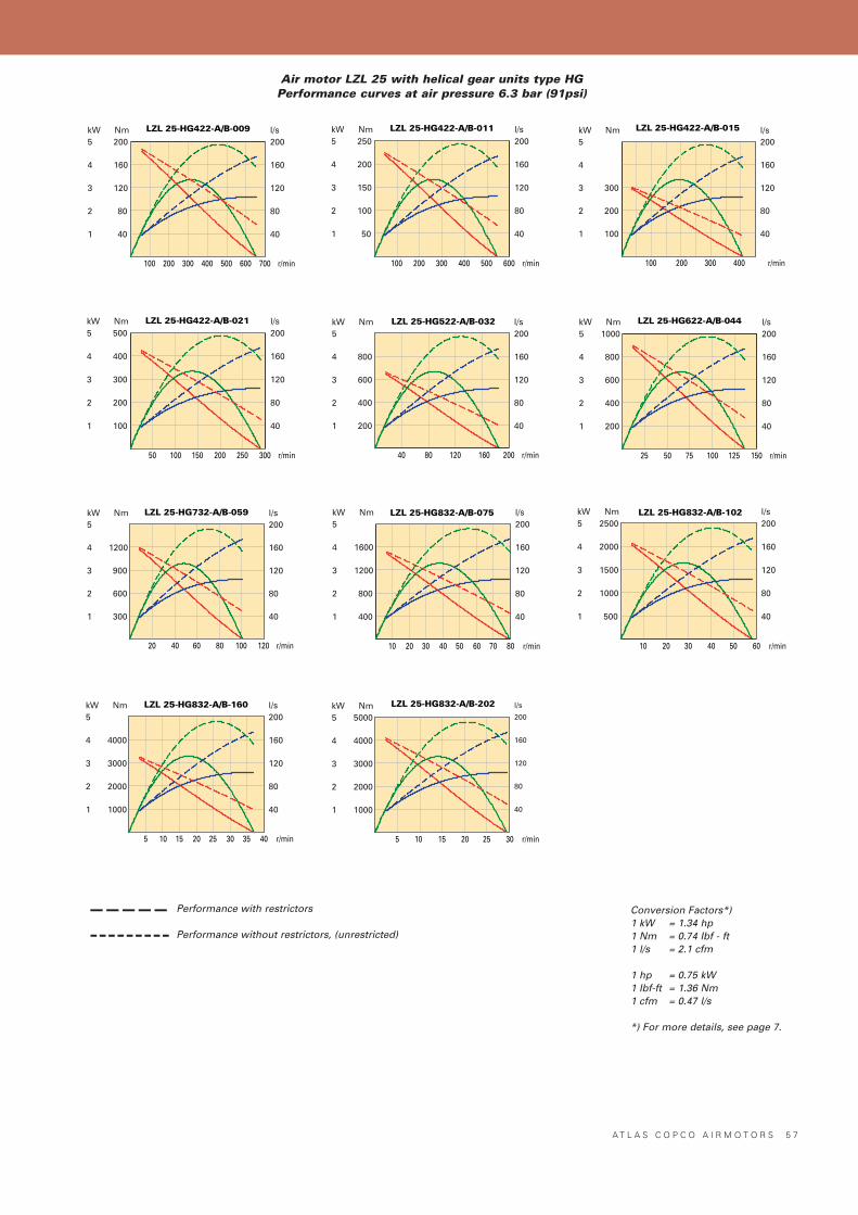
A T L A S C O P C O A I R M O T O R S 5 7
LZL 25-HG422-A/B-009
100 200 300 400 500 600 700 r/min
40
80
120
160
200l/s
1
2
3
4
5kW
40
80
120
160
200Nm LZL 25-HG422-A/B-015
100 200 300 400 r/min
40
80
120
160
200l/s
1
2
3
4
5kW
100
200
300
Nm
LZL 25-HG422-A/B-021
50 100 150 200 250 300 r/min
40
80
120
160
200l/s
1
2
3
4
5kW
100
200
300
400
500Nm
LZL 25-HG422-A/B-011
100 200 300 400 500 600 r/min
40
80
120
160
200l/s
1
2
3
4
5kW
50
100
150
200
250Nm
LZL 25-HG522-A/B-032
40 80 120 160 200 r/min
40
80
120
160
200l/s
1
2
3
4
5kW
200
400
600
800
Nm LZL 25-HG622-A/B-044
25 50 75 100 125 150 r/min
40
80
120
160
200l/s
1
2
3
4
5kW
200
400
600
800
1000Nm
LZL 25-HG732-A/B-059
20 40 60 80 100 120 r/min
40
80
120
160
200l/s
1
2
3
4
5kW
300
600
900
1200
Nm LZL 25-HG832-A/B-075
10 20 30 40 50 60 70 80 r/min
40
80
120
160
200l/s
1
2
3
4
5kW
400
800
1200
1600
Nm LZL 25-HG832-A/B-102
10 20 30 40 50 60 r/min
40
80
120
160
200l/s
1
2
3
4
5kW
500
1000
1500
2000
2500Nm
LZL 25-HG832-A/B-160
5 10 15 20 25 30 35 40 r/min
40
80
120
160
200l/s
1
2
3
4
5kW
1000
2000
3000
4000
Nm LZL 25-HG832-A/B-202
5 10 15 20 25 30 r/min
40
80
120
160
200
l/s
1
2
3
4
5kW
1000
2000
3000
4000
5000Nm
Conversion Factors*)1 kW = 1.34 hp1 Nm = 0.74 Ibf - ft1 l/s = 2.1 cfm
1 hp = 0.75 kW1 Ibf-ft = 1.36 Nm1 cfm = 0.47 l/s
*) For more details, see page 7.
Air motor LZL 25 with helical gear units type HGPerformance curves at air pressure 6.3 bar (91psi)
Performance with restrictors
Performance without restrictors, (unrestricted)
–––––---------
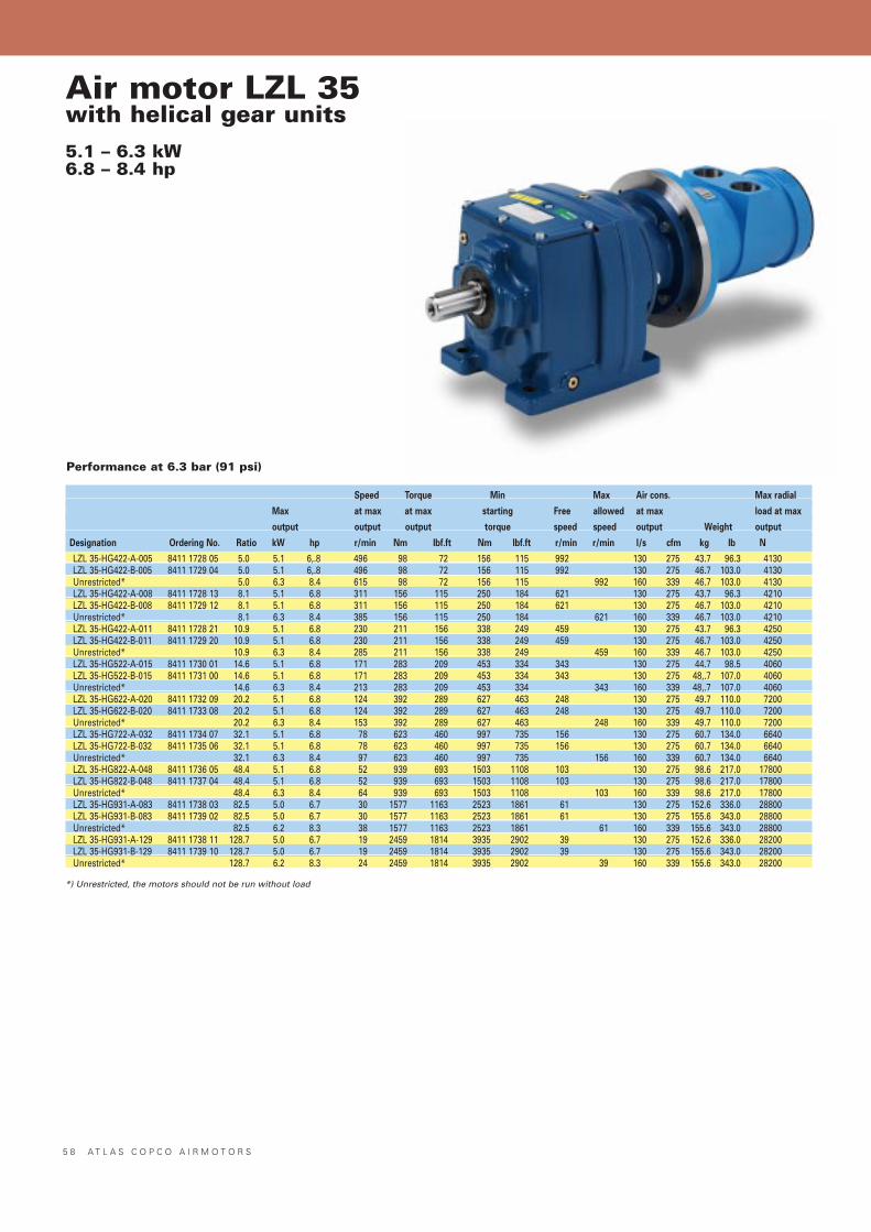
5 8 A T L A S C O P C O A I R M O T O R S
Air motor LZL 35with helical gear units5.1 – 6.3 kW6.8 – 8.4 hp
Performance at 6.3 bar (91 psi)
Speed Torque Min Max Air cons. Max radial
Max at max at max starting Free allowed at max load at max
output output output torque speed speed output Weight output
Designation Ordering No. Ratio kW hp r/min Nm lbf.ft Nm lbf.ft r/min r/min l/s cfm kg lb N
LZL 35-HG422-A-005 8411 1728 05 5.0 5.1 6,.8 496 98 72 156 115 992 130 275 43.7 96.3 4130LZL 35-HG422-B-005 8411 1729 04 5.0 5.1 6,.8 496 98 72 156 115 992 130 275 46.7 103.0 4130Unrestricted* 5.0 6.3 8.4 615 98 72 156 115 992 160 339 46.7 103.0 4130LZL 35-HG422-A-008 8411 1728 13 8.1 5.1 6.8 311 156 115 250 184 621 130 275 43.7 96.3 4210LZL 35-HG422-B-008 8411 1729 12 8.1 5.1 6.8 311 156 115 250 184 621 130 275 46.7 103.0 4210Unrestricted* 8.1 6.3 8.4 385 156 115 250 184 621 160 339 46.7 103.0 4210LZL 35-HG422-A-011 8411 1728 21 10.9 5.1 6.8 230 211 156 338 249 459 130 275 43.7 96.3 4250LZL 35-HG422-B-011 8411 1729 20 10.9 5.1 6.8 230 211 156 338 249 459 130 275 46.7 103.0 4250Unrestricted* 10.9 6.3 8.4 285 211 156 338 249 459 160 339 46.7 103.0 4250LZL 35-HG522-A-015 8411 1730 01 14.6 5.1 6.8 171 283 209 453 334 343 130 275 44.7 98.5 4060LZL 35-HG522-B-015 8411 1731 00 14.6 5.1 6.8 171 283 209 453 334 343 130 275 48,.7 107.0 4060Unrestricted* 14.6 6.3 8.4 213 283 209 453 334 343 160 339 48,.7 107.0 4060LZL 35-HG622-A-020 8411 1732 09 20.2 5.1 6.8 124 392 289 627 463 248 130 275 49.7 110.0 7200LZL 35-HG622-B-020 8411 1733 08 20.2 5.1 6.8 124 392 289 627 463 248 130 275 49.7 110.0 7200Unrestricted* 20.2 6.3 8.4 153 392 289 627 463 248 160 339 49.7 110.0 7200LZL 35-HG722-A-032 8411 1734 07 32.1 5.1 6.8 78 623 460 997 735 156 130 275 60.7 134.0 6640LZL 35-HG722-B-032 8411 1735 06 32.1 5.1 6.8 78 623 460 997 735 156 130 275 60.7 134.0 6640Unrestricted* 32.1 6.3 8.4 97 623 460 997 735 156 160 339 60.7 134.0 6640LZL 35-HG822-A-048 8411 1736 05 48.4 5.1 6.8 52 939 693 1503 1108 103 130 275 98.6 217.0 17800LZL 35-HG822-B-048 8411 1737 04 48.4 5.1 6.8 52 939 693 1503 1108 103 130 275 98.6 217.0 17800Unrestricted* 48.4 6.3 8.4 64 939 693 1503 1108 103 160 339 98.6 217.0 17800LZL 35-HG931-A-083 8411 1738 03 82.5 5.0 6.7 30 1577 1163 2523 1861 61 130 275 152.6 336.0 28800LZL 35-HG931-B-083 8411 1739 02 82.5 5.0 6.7 30 1577 1163 2523 1861 61 130 275 155.6 343.0 28800Unrestricted* 82.5 6.2 8.3 38 1577 1163 2523 1861 61 160 339 155.6 343.0 28800LZL 35-HG931-A-129 8411 1738 11 128.7 5.0 6.7 19 2459 1814 3935 2902 39 130 275 152.6 336.0 28200LZL 35-HG931-B-129 8411 1739 10 128.7 5.0 6.7 19 2459 1814 3935 2902 39 130 275 155.6 343.0 28200Unrestricted* 128.7 6.2 8.3 24 2459 1814 3935 2902 39 160 339 155.6 343.0 28200
*) Unrestricted, the motors should not be run without load
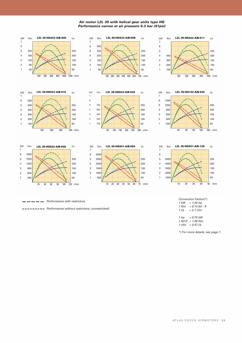
K A P I T E L R U B R I K
A T L A S C O P C O A I R M O T O R S 5 9
Air motor LZL 35 with helical gear units type HGPerformance curves at air pressure 6.3 bar (91psi)
LZL 35-HG422-A/B-005
200 400 600 800 1000 1200 r/min
50
100
150
200
250
l/s
1
2
3
4
5
6
7kW
40
80
120
160
200
Nm LZL 35-HG422-A/B-008
100 200 300 400 500 600 700 r/min
50
100
150
200
250
l/s
1
2
3
4
5
6
7kW
50
100
150
200
250
300
Nm LZL 35-HG422-A/B-011
100 200 300 400 500 r/min
50
100
150
200
250
l/s
1
2
3
4
5
6
7kW
100
200
300
400
Nm
LZL 35-HG522-A/B-015
100 200 300 400 r/min
50
100
150
200
250
l/s
1
2
3
4
5
6
7kW
100
200
300
400
500
600
Nm LZL 35-HG622-A/B-020
50 100 150 200 250 300 r/min
50
100
150
200
250
l/s
1
2
3
4
5
6
7
kW
150
300
450
600
750
Nm LZL 35-HG722-A/B-032
40 80 120 160 200 r/min
50
100
150
200
250
l/s
1
2
3
4
5
6
7kW
200
400
600
800
1000
1200
Nm
LZL 35-HG822-A/B-048
20 40 60 80 100 120 r/min
50
100
150
200
250
l/s
1
2
3
4
5
6
7kW
300
600
900
1200
1500
1800
Nm LZL 35-HG931-A/B-083
10 20 30 40 50 60 70 r/min
50
100
150
200
250
l/s
1
2
3
4
5
6
7kW
500
1000
1500
2000
2500
3000
Nm LZL 35-HG931-A/B-129
10 20 30 40 50 r/min
50
100
150
200
250
l/s
1
2
3
4
5
6
7kW
1000
2000
3000
4000
5000
Nm
Conversion Factors*)1 kW = 1.34 hp1 Nm = 0.74 Ibf - ft1 l/s = 2.1 cfm
1 hp = 0.75 kW1 Ibf-ft = 1.36 Nm1 cfm = 0.47 l/s
*) For more details, see page 7.
Performance with restrictors
Performance without restrictors, (unrestricted)
–––––---------
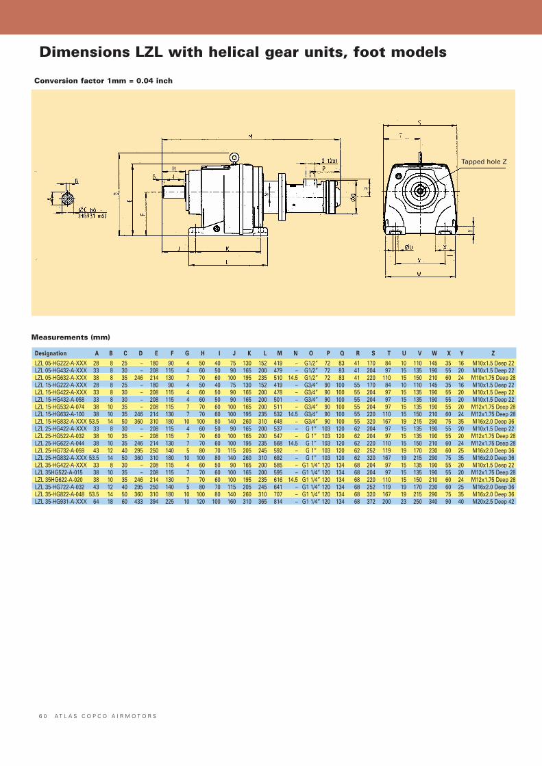
6 0 A T L A S C O P C O A I R M O T O R S
Dimensions LZL with helical gear units, foot models
DesignationDesignation AA BB CC DD E E FF GG H H II JJ KK LL MM NN OO PP QQ RR SS TT UU VV WW XX Y Y ZZ
LZL 05-HG222-A-XXX 28 8 25 – 180 90 4 50 40 75 130 152 419 – G1/2” 72 83 41 170 84 10 110 145 35 16 M10x1.5 Deep 22LZL 05-HG432-A-XXX 33 8 30 – 208 115 4 60 50 90 165 200 479 – G1/2” 72 83 41 204 97 15 135 190 55 20 M10x1.5 Deep 22LZL 05-HG632-A-XXX 38 8 35 246 214 130 7 70 60 100 195 235 510 14.5 G1/2” 72 83 41 220 110 15 150 210 60 24 M10x1.75 Deep 28LZL 15-HG222-A-XXX 28 8 25 – 180 90 4 50 40 75 130 152 419 – G3/4” 90 100 55 170 84 10 110 145 35 16 M10x1.5 Deep 22LZL 15-HG422-A-XXX 33 8 30 – 208 115 4 60 50 90 165 200 478 – G3/4” 90 100 55 204 97 15 135 190 55 20 M10x1.5 Deep 22LZL 15-HG432-A-058 33 8 30 – 208 115 4 60 50 90 165 200 501 – G3/4” 90 100 55 204 97 15 135 190 55 20 M10x1.5 Deep 22LZL 15-HG532-A-074 38 10 35 – 208 115 7 70 60 100 165 200 511 – G3/4” 90 100 55 204 97 15 135 190 55 20 M12x1.75 Deep 28LZL 15-HG632-A-100 38 10 35 246 214 130 7 70 60 100 195 235 532 14.5 G3/4” 90 100 55 220 110 15 150 210 60 24 M12x1.75 Deep 28LZL 15-HG832-A-XXX 53.5 14 50 360 310 180 10 100 80 140 260 310 648 – G3/4” 90 100 55 320 167 19 215 290 75 35 M16x2.0 Deep 36LZL 25-HG422-A-XXX 33 8 30 – 208 115 4 60 50 90 165 200 537 – G 1” 103 120 62 204 97 15 135 190 55 20 M10x1.5 Deep 22LZL 25-HG522-A-032 38 10 35 – 208 115 7 70 60 100 165 200 547 – G 1” 103 120 62 204 97 15 135 190 55 20 M12x1.75 Deep 28LZL 25-HG622-A-044 38 10 35 246 214 130 7 70 60 100 195 235 568 14.5 G 1” 103 120 62 220 110 15 150 210 60 24 M12x1.75 Deep 28LZL 25-HG732-A-059 43 12 40 295 250 140 5 80 70 115 205 245 592 – G 1” 103 120 62 252 119 19 170 230 60 25 M16x2.0 Deep 36LZL 25-HG832-A-XXX 53.5 14 50 360 310 180 10 100 80 140 260 310 692 – G 1” 103 120 62 320 167 19 215 290 75 35 M16x2.0 Deep 36LZL 35-HG422-A-XXX 33 8 30 – 208 115 4 60 50 90 165 200 585 – G1 1/4” 120 134 68 204 97 15 135 190 55 20 M10x1.5 Deep 22LZL 35HG522-A-015 38 10 35 – 208 115 7 70 60 100 165 200 595 – G1 1/4” 120 134 68 204 97 15 135 190 55 20 M12x1.75 Deep 28LZL 35HG622-A-020 38 10 35 246 214 130 7 70 60 100 195 235 616 14.5 G1 1/4” 120 134 68 220 110 15 150 210 60 24 M12x1.75 Deep 28LZL 35-HG722-A-032 43 12 40 295 250 140 5 80 70 115 205 245 641 – G1 1/4” 120 134 68 252 119 19 170 230 60 25 M16x2.0 Deep 36LZL 35-HG822-A-048 53.5 14 50 360 310 180 10 100 80 140 260 310 707 – G1 1/4” 120 134 68 320 167 19 215 290 75 35 M16x2.0 Deep 36LZL 35-HG931-A-XXX 64 18 60 433 394 225 10 120 100 160 310 365 814 – G1 1/4” 120 134 68 372 200 23 250 340 90 40 M20x2.5 Deep 42
Conversion factor 1mm = 0.04 inch
Measurements (mm)
Tapped hole Z
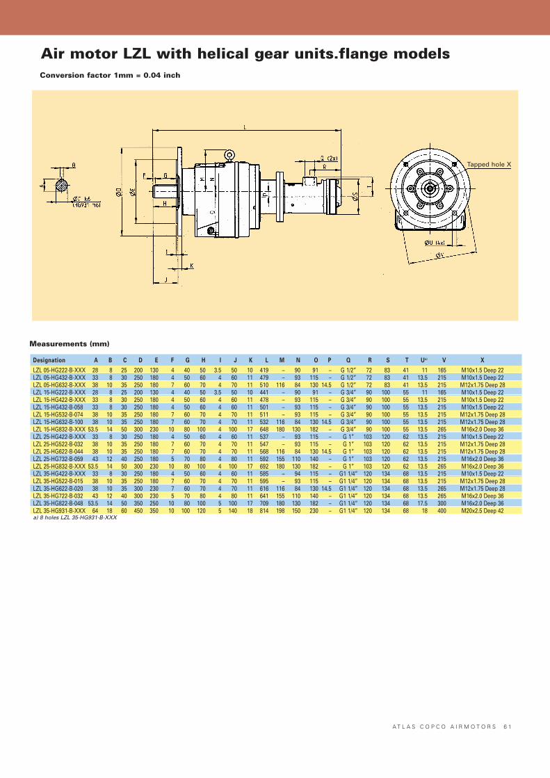
A T L A S C O P C O A I R M O T O R S 6 1
Air motor LZL with helical gear units.flange modelsConversion factor 1mm = 0.04 inch
DesignationDesignation AA BB CC DD E E FF GG H H II JJ KK LL MM NN OO PP QQ RR SS TT UU a)a) VV XX
LZL 05-HG222-B-XXX 28 8 25 200 130 4 40 50 3.5 50 10 419 – 90 91 – G 1/2” 72 83 41 11 165 M10x1.5 Deep 22LZL 05-HG432-B-XXX 33 8 30 250 180 4 50 60 4 60 11 479 – 93 115 – G 1/2” 72 83 41 13.5 215 M10x1.5 Deep 22LZL 05-HG632-B-XXX 38 10 35 250 180 7 60 70 4 70 11 510 116 84 130 14.5 G 1/2” 72 83 41 13.5 215 M12x1.75 Deep 28LZL 15-HG222-B-XXX 28 8 25 200 130 4 40 50 3.5 50 10 441 – 90 91 – G 3/4” 90 100 55 11 165 M10x1.5 Deep 22LZL 15-HG422-B-XXX 33 8 30 250 180 4 50 60 4 60 11 478 – 93 115 – G 3/4” 90 100 55 13.5 215 M10x1.5 Deep 22LZL 15-HG432-B-058 33 8 30 250 180 4 50 60 4 60 11 501 – 93 115 – G 3/4” 90 100 55 13.5 215 M10x1.5 Deep 22LZL 15-HG532-B-074 38 10 35 250 180 7 60 70 4 70 11 511 – 93 115 – G 3/4” 90 100 55 13.5 215 M12x1.75 Deep 28LZL 15-HG632-B-100 38 10 35 250 180 7 60 70 4 70 11 532 116 84 130 14.5 G 3/4” 90 100 55 13.5 215 M12x1.75 Deep 28LZL 15-HG832-B-XXX 53.5 14 50 300 230 10 80 100 4 100 17 648 180 130 182 – G 3/4” 90 100 55 13.5 265 M16x2.0 Deep 36LZL 25-HG422-B-XXX 33 8 30 250 180 4 50 60 4 60 11 537 – 93 115 – G 1” 103 120 62 13.5 215 M10x1.5 Deep 22LZL 25-HG522-B-032 38 10 35 250 180 7 60 70 4 70 11 547 – 93 115 – G 1” 103 120 62 13.5 215 M12x1.75 Deep 28LZL 25-HG622-B-044 38 10 35 250 180 7 60 70 4 70 11 568 116 84 130 14.5 G 1” 103 120 62 13.5 215 M12x1.75 Deep 28LZL 25-HG732-B-059 43 12 40 250 180 5 70 80 4 80 11 592 155 110 140 – G 1” 103 120 62 13.5 215 M16x2.0 Deep 36LZL 25-HG832-B-XXX 53.5 14 50 300 230 10 80 100 4 100 17 692 180 130 182 – G 1” 103 120 62 13.5 265 M16x2.0 Deep 36LZL 35-HG422-B-XXX 33 8 30 250 180 4 50 60 4 60 11 585 – 94 115 – G1 1/4” 120 134 68 13.5 215 M10x1.5 Deep 22LZL 35-HG522-B-015 38 10 35 250 180 7 60 70 4 70 11 595 – 93 115 – G1 1/4” 120 134 68 13.5 215 M12x1.75 Deep 28LZL 35-HG622-B-020 38 10 35 300 230 7 60 70 4 70 11 616 116 84 130 14.5 G1 1/4” 120 134 68 13.5 265 M12x1.75 Deep 28LZL 35-HG722-B-032 43 12 40 300 230 5 70 80 4 80 11 641 155 110 140 – G1 1/4” 120 134 68 13.5 265 M16x2.0 Deep 36LZL 35-HG822-B-048 53.5 14 50 350 250 10 80 100 5 100 17 709 180 130 182 – G1 1/4” 120 134 68 17.5 300 M16x2.0 Deep 36LZL 35-HG931-B-XXX 64 18 60 450 350 10 100 120 5 140 18 814 198 150 230 – G1 1/4” 120 134 68 18 400 M20x2.5 Deep 42a) 8 holes LZL 35-HG931-B-XXX
Measurements (mm)
Tapped hole X
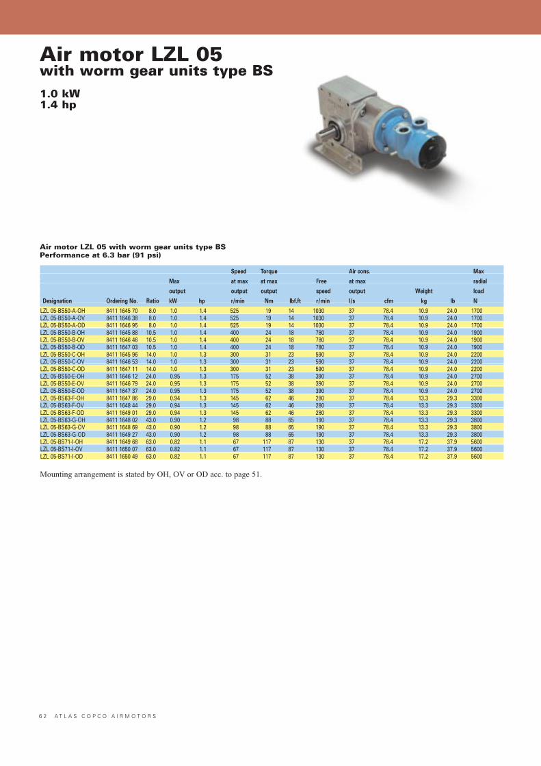
6 2 A T L A S C O P C O A I R M O T O R S
Air motor LZL 05with worm gear units type BS1.0 kW1.4 hp
Air motor LZL 05 with worm gear units type BSPerformance at 6.3 bar (91 psi)
Speed Torque Air cons. Max
Max at max at max Free at max radial
output output output speed output Weight load
Designation Ordering No. Ratio kW hp r/min Nm lbf.ft r/min l/s cfm kg lb N
LZL 05-BS50-A-OH 8411 1645 70 8.0 1.0 1.4 525 19 14 1030 37 78.4 10.9 24.0 1700LZL 05-BS50-A-OV 8411 1646 38 8.0 1.0 1.4 525 19 14 1030 37 78.4 10.9 24.0 1700LZL 05-BS50-A-OD 8411 1646 95 8.0 1.0 1.4 525 19 14 1030 37 78.4 10.9 24.0 1700LZL 05-BS50-B-OH 8411 1645 88 10.5 1.0 1.4 400 24 18 780 37 78.4 10.9 24.0 1900LZL 05-BS50-B-OV 8411 1646 46 10.5 1.0 1.4 400 24 18 780 37 78.4 10.9 24.0 1900LZL 05-BS50-B-OD 8411 1647 03 10.5 1.0 1.4 400 24 18 780 37 78.4 10.9 24.0 1900LZL 05-BS50-C-OH 8411 1645 96 14.0 1.0 1.3 300 31 23 590 37 78.4 10.9 24.0 2200LZL 05-BS50-C-OV 8411 1646 53 14.0 1.0 1.3 300 31 23 590 37 78.4 10.9 24.0 2200LZL 05-BS50-C-OD 8411 1647 11 14.0 1.0 1.3 300 31 23 590 37 78.4 10.9 24.0 2200LZL 05-BS50-E-OH 8411 1646 12 24.0 0.95 1.3 175 52 38 390 37 78.4 10.9 24.0 2700LZL 05-BS50-E-OV 8411 1646 79 24.0 0.95 1.3 175 52 38 390 37 78.4 10.9 24.0 2700LZL 05-BS50-E-OD 8411 1647 37 24.0 0.95 1.3 175 52 38 390 37 78.4 10.9 24.0 2700LZL 05-BS63-F-OH 8411 1647 86 29.0 0.94 1.3 145 62 46 280 37 78.4 13.3 29.3 3300LZL 05-BS63-F-OV 8411 1648 44 29.0 0.94 1.3 145 62 46 280 37 78.4 13.3 29.3 3300LZL 05-BS63-F-OD 8411 1649 01 29.0 0.94 1.3 145 62 46 280 37 78.4 13.3 29.3 3300LZL 05-BS63-G-OH 8411 1648 02 43.0 0.90 1.2 98 88 65 190 37 78.4 13.3 29.3 3800LZL 05-BS63-G-OV 8411 1648 69 43.0 0.90 1.2 98 88 65 190 37 78.4 13.3 29.3 3800LZL 05-BS63-G-OD 8411 1649 27 43.0 0.90 1.2 98 88 65 190 37 78.4 13.3 29.3 3800LZL 05-BS71-I-OH 8411 1649 68 63.0 0.82 1.1 67 117 87 130 37 78.4 17.2 37.9 5600LZL 05-BS71-I-OV 8411 1650 07 63.0 0.82 1.1 67 117 87 130 37 78.4 17.2 37.9 5600LZL 05-BS71-I-OD 8411 1650 49 63.0 0.82 1.1 67 117 87 130 37 78.4 17.2 37.9 5600
Mounting arrangement is stated by OH, OV or OD acc. to page 51.
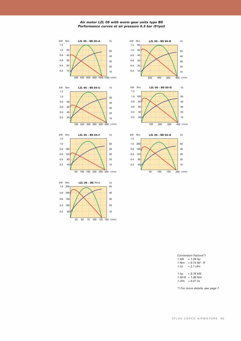
A T L A S C O P C O A I R M O T O R S 6 3
Nm LZL 05 – BS 50–A l/s
r/min
kW
1200400 600 800
1.2
1.0
0.8
0.6
0.4
0.2
200 1000
50
40
30
20
10
50
40
30
20
10
Nm LZL 05 – BS 50–B l/s
r/min
kW
800400 600
1.2
1.0
0.8
0.6
0.4
0.2
200
60
50
40
30
20
10
50
40
30
20
10
Nm LZL 05 – BS 50–C l/s
r/min
kW
400 600
1.2
1.0
0.8
0.6
0.4
0.2
200
80
60
40
20
50
40
30
20
10
500300100
Nm LZL 05 – BS 63–F l/s
r/min
kW
200 300
1.2
1.0
0.8
0.6
0.4
0.2
100
160
120
80
40
50
40
30
20
10
25015050
Nm LZL 05 – BS 63–G l/s
r/min
kW
200
1.2
1.0
0.8
0.6
0.4
0.2
100
200
160
120
80
40
50
40
30
20
10
15050
Nm LZL 05 – BS 71–I l/s
r/min
kW
150
1.0
0.8
0.6
0.4
0.2
75
250
200
150
100
50
50
40
30
20
10
1005025 125
Nm LZL 05 – BS 50–G l/s
r/min
kW
200 300
1.2
1.0
0.8
0.6
0.4
0.2
100
100
80
60
40
20
50
40
30
20
10
400
Conversion Factors*)1 kW = 1.34 hp1 Nm = 0.74 Ibf - ft1 l/s = 2.1 cfm
1 hp = 0.75 kW1 Ibf-ft = 1.36 Nm1 cfm = 0.47 l/s
*) For more details, see page 7.
Air motor LZL 05 with worm gear units type BSPerformance curves at air pressure 6.3 bar (91psi)
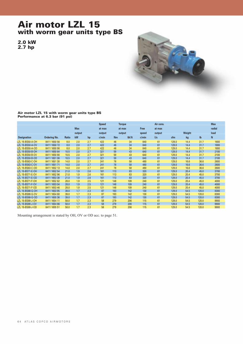
6 4 A T L A S C O P C O A I R M O T O R S
Air motor LZL 15with worm gear units type BS2.0 kW2.7 hp
Air motor LZL 15 with worm gear units type BSPerformance at 6.3 bar (91 psi)
Speed Torque Air cons. Max
Max at max at max Free at max radial
output output output speed output Weight load
Designation Ordering No. Ratio kW hp r/min Nm lbf.ft r/min l/s cfm kg lb N
LZL 15-BS50-A-OH 8411 1650 56 8.0 2.0 2.7 422 46 34 840 61 129.0 14.4 31.7 1800LZL 15-BS50-A-OV 8411 1650 72 8.0 2.0 2.7 422 46 34 840 61 129.0 14.4 31.7 1800LZL 15-BS50-A-OD 8411 1650 98 8.0 2.0 2.7 422 46 34 840 61 129.0 14.4 31.7 1800LZL 15-BS50-B-OH 8411 1650 64 10.5 2.0 2.7 321 59 43 640 61 129.0 14.4 31.7 2100LZL 15-BS50-B-OV 8411 1650 80 10.5 2.0 2.7 321 59 43 640 61 129.0 14.4 31.7 2100LZL 15-BS50-B-OD 8411 1651 06 10.5 2.0 2.7 321 59 43 640 61 129.0 14.4 31.7 2100LZL 15-BS63-C-OH 8411 1651 30 14.0 2.0 2.7 241 78 58 480 61 129.0 16.6 36.6 2600LZL 15-BS63-C-OV 8411 1651 71 14.0 2.0 2.7 241 78 58 480 61 129.0 16.6 36.6 2600LZL 15-BS63-C-OD 8411 1652 13 14.0 2.0 2.7 241 78 58 480 61 129.0 16.6 36.6 2600LZL 15-BS71-E-OH 8411 1652 54 21.0 1.9 2.6 161 113 83 320 61 129.0 20.4 45.0 3700LZL 15-BS71-E-OV 8411 1652 96 21.0 1.9 2.6 161 113 83 320 61 129.0 20.4 45.0 3700LZL 15-BS71-E-OD 8411 1653 38 21.0 1.9 2.6 161 113 83 320 61 129.0 20.4 45.0 3700LZL 15-BS71-F-OH 8411 1652 62 28.0 1.9 2.5 121 148 109 240 61 129.0 20.4 45.0 4000LZL 15-BS71-F-OV 8411 1653 04 28.0 1.9 2.5 121 148 109 240 61 129.0 20.4 45.0 4000LZL 15-BS71-F-OD 8411 1653 46 28.0 1.9 2.5 121 148 109 240 61 129.0 20.4 45.0 4000LZL 15-BS88-G-OH 8411 1653 95 39.0 1.7 2.3 87 193 142 130 61 129.0 54.5 120.0 8300LZL 15-BS88-G-OV 8411 1654 60 39.0 1.7 2.3 87 193 142 130 61 129.0 54.5 120.0 8300LZL 15-BS88-G-OD 8411 1655 36 39.0 1.7 2.3 87 193 142 130 61 129.0 54.5 120.0 8300LZL 15-BS88-J-OH 8411 1654 11 58.0 1.7 2.3 58 279 206 115 61 129.0 54.5 120.0 9900LZL 15-BS88-J-OV 8411 1654 86 58.0 1.7 2.3 58 279 206 115 61 129.0 54.5 120.0 9900LZL 15-BS88-J-OD 8411 1655 51 58.0 1.7 2.3 58 279 206 115 61 129.0 54.5 120.0 9900
Mounting arrangement is stated by OH, OV or OD acc. to page 51.
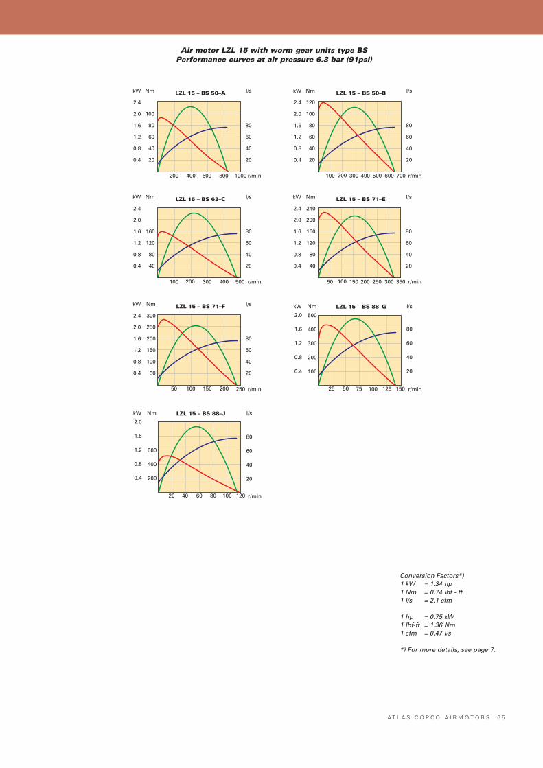
A T L A S C O P C O A I R M O T O R S 6 5
Nm
100
80
60
40
20
LZL 15 – BS 50–A l/s
80
60
40
20
200 r/min
kW
2.4
2.0
1.6
1.2
0.8
0.4
400 600 800 1000
Nm
120
100
80
60
40
20
LZL 15 – BS 50–B l/s
80
60
40
20
200 r/min
kW
2.4
2.0
1.6
1.2
0.8
0.4
300 400 600 700100 500
Nm
160
120
80
40
LZL 15 – BS 63–C l/s
80
60
40
20
200 r/min
kW
2.4
2.0
1.6
1.2
0.8
0.4
300 400100 500
Nm
240
200
160
120
80
40
LZL 15 – BS 71–E l/s
80
60
40
20
100 r/min
kW
2.4
2.0
1.6
1.2
0.8
0.4
150 200 300 35050 250
Nm
300
250
200
150
100
50
LZL 15 – BS 71–F l/s
80
60
40
20
r/min
kW
2.4
2.0
1.6
1.2
0.8
0.4
100 25050 150 200
Nm LZL 15 – BS 88–J l/s
r/min
kW
12040 60 80
600
400
200
2.0
1.6
1.2
0.8
0.4
80
60
40
20
20 100
Nm LZL 15 – BS 88–G l/s
r/min
kW
7550 100 125
500
400
300
200
100
2.0
1.6
1.2
0.8
0.4
80
60
40
20
25 150
Conversion Factors*)1 kW = 1.34 hp1 Nm = 0.74 Ibf - ft1 l/s = 2.1 cfm
1 hp = 0.75 kW1 Ibf-ft = 1.36 Nm1 cfm = 0.47 l/s
*) For more details, see page 7.
Air motor LZL 15 with worm gear units type BSPerformance curves at air pressure 6.3 bar (91psi)
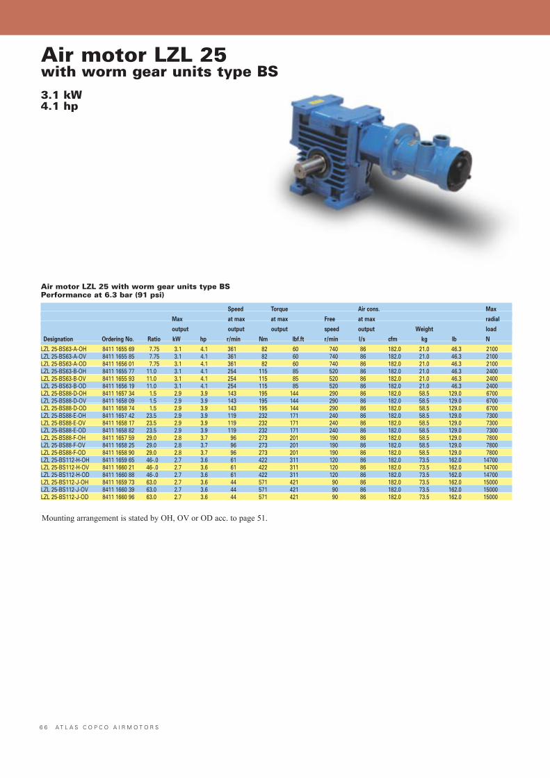
6 6 A T L A S C O P C O A I R M O T O R S
Air motor LZL 25with worm gear units type BS3.1 kW4.1 hp
Air motor LZL 25 with worm gear units type BSPerformance at 6.3 bar (91 psi)
Mounting arrangement is stated by OH, OV or OD acc. to page 51.
Speed Torque Air cons. Max
Max at max at max Free at max radial
output output output speed output Weight load
Designation Ordering No. Ratio kW hp r/min Nm lbf.ft r/min l/s cfm kg lb N
LZL 25-BS63-A-OH 8411 1655 69 7.75 3.1 4.1 361 82 60 740 86 182.0 21.0 46.3 2100LZL 25-BS63-A-OV 8411 1655 85 7.75 3.1 4.1 361 82 60 740 86 182.0 21.0 46.3 2100LZL 25-BS63-A-OD 8411 1656 01 7.75 3.1 4.1 361 82 60 740 86 182.0 21.0 46.3 2100LZL 25-BS63-B-OH 8411 1655 77 11.0 3.1 4.1 254 115 85 520 86 182.0 21.0 46.3 2400LZL 25-BS63-B-OV 8411 1655 93 11.0 3.1 4.1 254 115 85 520 86 182.0 21.0 46.3 2400LZL 25-BS63-B-OD 8411 1656 19 11.0 3.1 4.1 254 115 85 520 86 182.0 21.0 46.3 2400LZL 25-BS88-D-OH 8411 1657 34 1.5 2.9 3.9 143 195 144 290 86 182.0 58.5 129.0 6700LZL 25-BS88-D-OV 8411 1658 09 1.5 2.9 3.9 143 195 144 290 86 182.0 58.5 129.0 6700LZL 25-BS88-D-OD 8411 1658 74 1.5 2.9 3.9 143 195 144 290 86 182.0 58.5 129.0 6700LZL 25-BS88-E-OH 8411 1657 42 23.5 2.9 3.9 119 232 171 240 86 182.0 58.5 129.0 7300LZL 25-BS88-E-OV 8411 1658 17 23.5 2.9 3.9 119 232 171 240 86 182.0 58.5 129.0 7300LZL 25-BS88-E-OD 8411 1658 82 23.5 2.9 3.9 119 232 171 240 86 182.0 58.5 129.0 7300LZL 25-BS88-F-OH 8411 1657 59 29.0 2.8 3.7 96 273 201 190 86 182.0 58.5 129.0 7800LZL 25-BS88-F-OV 8411 1658 25 29.0 2.8 3.7 96 273 201 190 86 182.0 58.5 129.0 7800LZL 25-BS88-F-OD 8411 1658 90 29.0 2.8 3.7 96 273 201 190 86 182.0 58.5 129.0 7800LZL 25-BS112-H-OH 8411 1659 65 46-.0 2.7 3.6 61 422 311 120 86 182.0 73.5 162.0 14700LZL 25-BS112-H-OV 8411 1660 21 46-.0 2.7 3.6 61 422 311 120 86 182.0 73.5 162.0 14700LZL 25-BS112-H-OD 8411 1660 88 46-.0 2.7 3.6 61 422 311 120 86 182.0 73.5 162.0 14700LZL 25-BS112-J-OH 8411 1659 73 63.0 2.7 3.6 44 571 421 90 86 182.0 73.5 162.0 15000LZL 25-BS112-J-OV 8411 1660 39 63.0 2.7 3.6 44 571 421 90 86 182.0 73.5 162.0 15000LZL 25-BS112-J-OD 8411 1660 96 63.0 2.7 3.6 44 571 421 90 86 182.0 73.5 162.0 15000
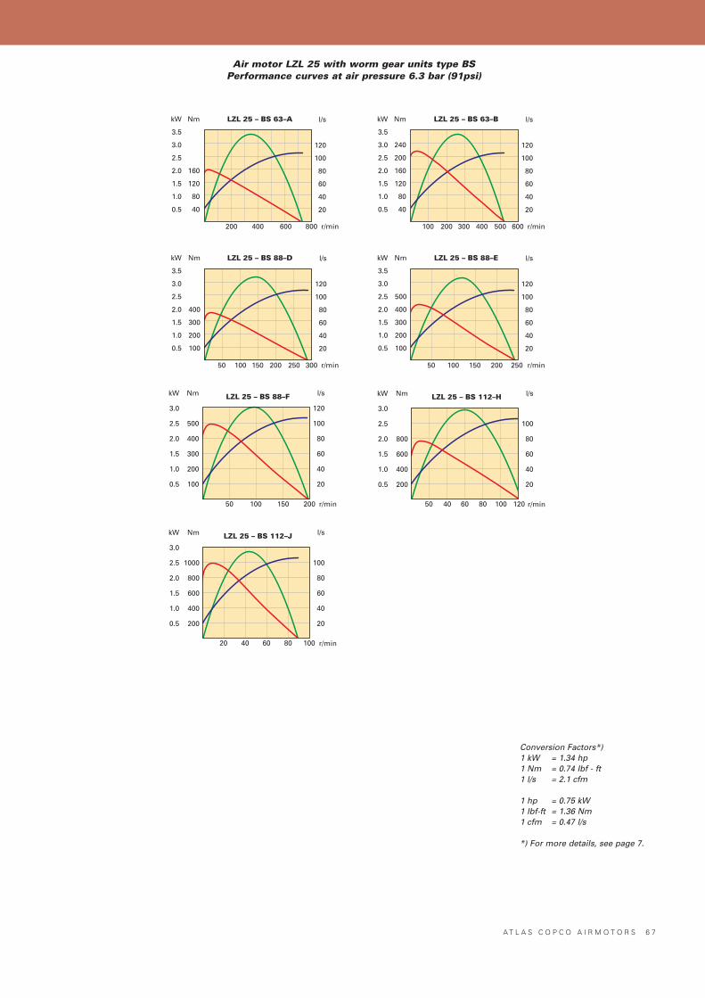
A T L A S C O P C O A I R M O T O R S 6 7
Nm
160
120
80
40
LZL 25 – BS 63–A l/s
120
100
80
60
40
20
200 r/min
kW
3.5
3.0
2.5
2.0
1.5
1.0
0.5
400 600 800
Nm
240
200
160
120
80
40
LZL 25 – BS 63–B l/s
120
100
80
60
40
20
200 r/min
kW
3.5
3.0
2.5
2.0
1.5
1.0
0.5
400 500 600300100
Nm
400
300
200
100
LZL 25 – BS 88–D l/s
120
100
80
60
40
20
100 r/min
kW
3.5
3.0
2.5
2.0
1.5
1.0
0.5
200 250 30015050
Nm
500
400
300
200
100
LZL 25 – BS 88–E l/s
120
100
80
60
40
20
100 r/min
kW
3.5
3.0
2.5
2.0
1.5
1.0
0.5
200 25015050
Nm
500
400
300
200
100
LZL 25 – BS 88–F l/s
120
100
80
60
40
20
100 r/min
kW
3.0
2.5
2.0
1.5
1.0
0.5
20015050
Nm
800
600
400
200
LZL 25 – BS 112–H l/s
100
80
60
40
20
40 r/min
kW
3.0
2.5
2.0
1.5
1.0
0.5
806050 100 120
Nm
1000
800
600
400
200
LZL 25 – BS 112–J l/s
100
80
60
40
20
40 r/min
kW
3.0
2.5
2.0
1.5
1.0
0.5
806020 100
Conversion Factors*)1 kW = 1.34 hp1 Nm = 0.74 Ibf - ft1 l/s = 2.1 cfm
1 hp = 0.75 kW1 Ibf-ft = 1.36 Nm1 cfm = 0.47 l/s
*) For more details, see page 7.
Air motor LZL 25 with worm gear units type BSPerformance curves at air pressure 6.3 bar (91psi)
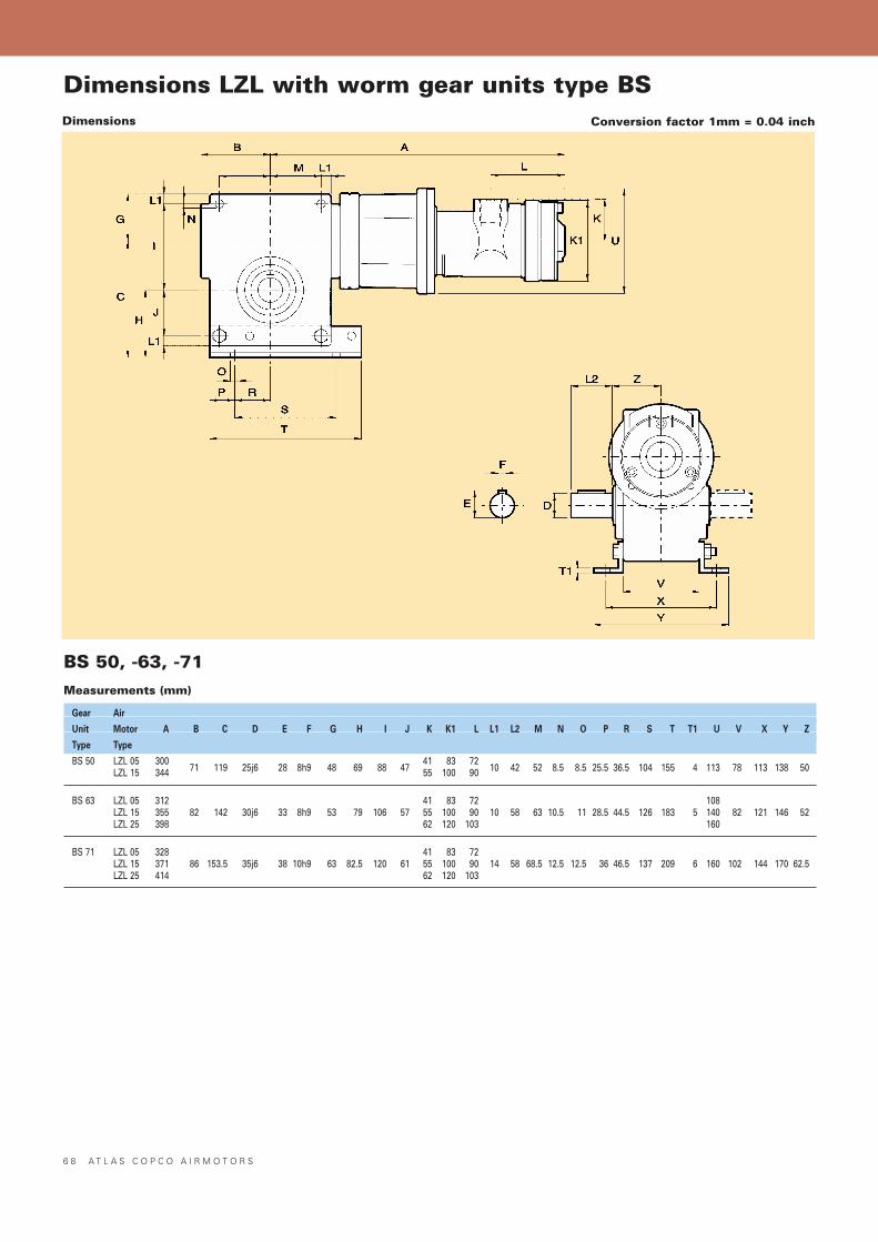
Conversion factor 1mm = 0.04 inchDimensions
6 8 A T L A S C O P C O A I R M O T O R S
BS 50, -63, -71Measurements (mm)
Dimensions LZL with worm gear units type BS
Gear Air
Unit Motor A B C D E F G H I J K K1 L L1 L2 M N O P R S T T1 U V X Y Z
Type Type
BS 50 LZL 05 300 41 83 72LZL 15 344 71 119 25j6 28 8h9 48 69 88 47 55 100 90 10 42 52 8.5 8.5 25.5 36.5 104 155 4 113 78 113 138 50
BS 63 LZL 05 312 41 83 72 108LZL 15 355 82 142 30j6 33 8h9 53 79 106 57 55 100 90 10 58 63 10.5 11 28.5 44.5 126 183 5 140 82 121 146 52LZL 25 398 62 120 103 160
BS 71 LZL 05 328 41 83 72LZL 15 371 86 153.5 35j6 38 10h9 63 82.5 120 61 55 100 90 14 58 68.5 12.5 12.5 36 46.5 137 209 6 160 102 144 170 62.5LZL 25 414 62 120 103
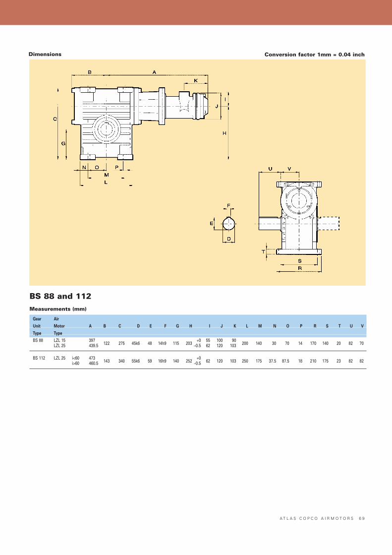
A T L A S C O P C O A I R M O T O R S 6 9
BS 88 and 112Measurements (mm)
Gear Air
Unit Motor A B C D E F G H I J K L M N O P R S T U V
Type Type
BS 88 LZL 15 397 +0 55 100 90LZL 25 439.5 122 275 45k6 48 14h9 115 203 –0.5 62 120 103 200 140 30 70 14 170 140 20 82 70
BS 112 LZL 25 i<60 473 +0i>60 460.5 143 340 55k6 59 16h9 140 252 –0.5 62 120 103 250 175 37.5 87.5 18 210 175 23 82 82
Conversion factor 1mm = 0.04 inchDimensions
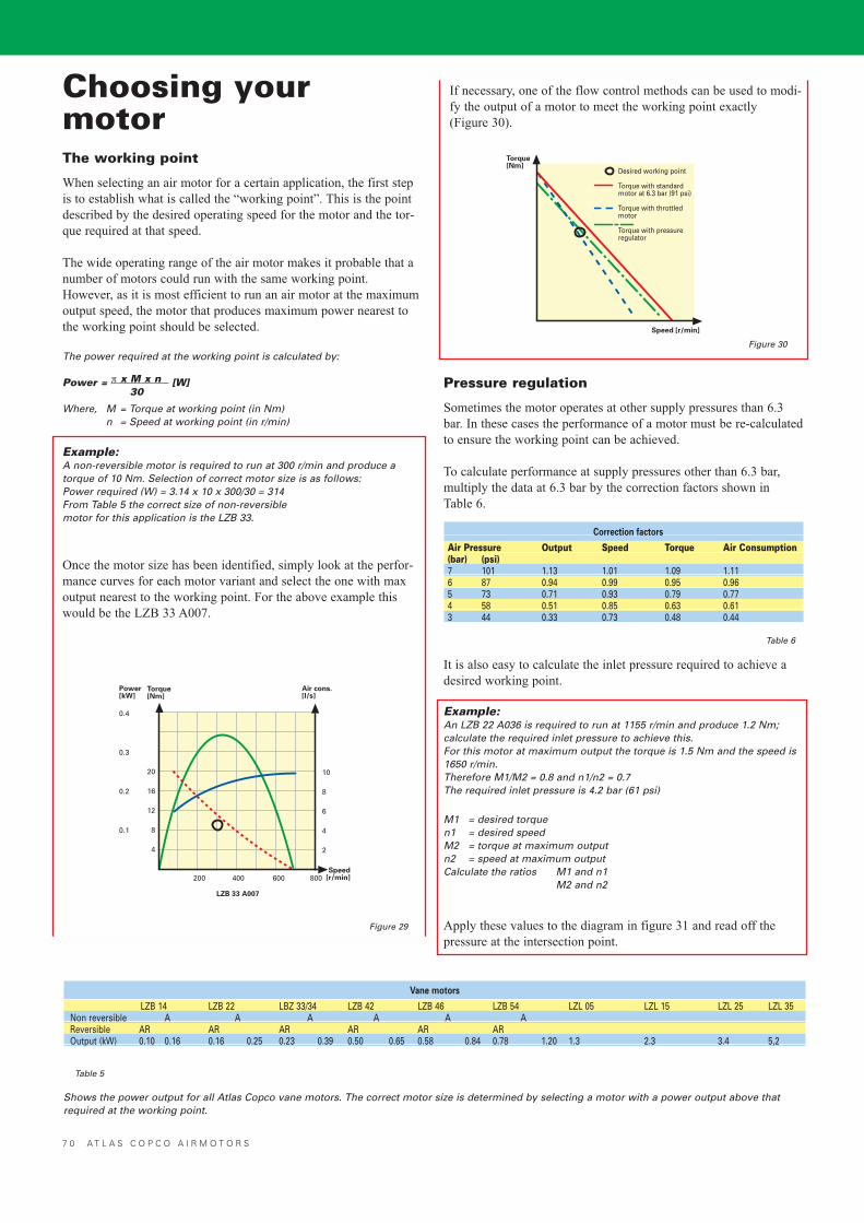
Torque[Nm]
Speed [r/min]
Desired working point
Torque with standardmotor at 6.3 bar (91 psi)
Torque with throttledmotor
Torque with pressureregulator
7 0 A T L A S C O P C O A I R M O T O R S
Choosing yourmotorThe working point
When selecting an air motor for a certain application, the first stepis to establish what is called the �working point�. This is the pointdescribed by the desired operating speed for the motor and the tor-que required at that speed.
The wide operating range of the air motor makes it probable that anumber of motors could run with the same working point.However, as it is most efficient to run an air motor at the maximumoutput speed, the motor that produces maximum power nearest tothe working point should be selected.
The power required at the working point is calculated by:
Power = π x M x n [W]30
Where, M = Torque at working point (in Nm)n = Speed at working point (in r/min)
Example:A non-reversible motor is required to run at 300 r/min and produce atorque of 10 Nm. Selection of correct motor size is as follows: Power required (W) = 3.14 x 10 x 300/30 = 314From Table 5 the correct size of non-reversible motor for this application is the LZB 33.
Once the motor size has been identified, simply look at the perfor-mance curves for each motor variant and select the one with maxoutput nearest to the working point. For the above example thiswould be the LZB 33 A007.
Apply these values to the diagram in figure 31 and read off thepressure at the intersection point.
Vane motors
LZB 14 LZB 22 LBZ 33/34 LZB 42 LZB 46 LZB 54 LZL 05 LZL 15 LZL 25 LZL 35Non reversible A A A A A AReversible AR AR AR AR AR AROutput (kW) 0.10 0.16 0.16 0.25 0.23 0.39 0.50 0.65 0.58 0.84 0.78 1.20 1.3 2.3 3.4 5,2
Shows the power output for all Atlas Copco vane motors. The correct motor size is determined by selecting a motor with a power output above thatrequired at the working point.
Table 5
Torque[Nm]
0.4
0.3
0.2
0.1
200Speed
[r/min]
Air cons.[l/s]
Power[kW]
20
16
12
8
4
10
8
6
4
2
400 600 800
LZB 33 A007
Pressure regulation
Sometimes the motor operates at other supply pressures than 6.3bar. In these cases the performance of a motor must be re-calculatedto ensure the working point can be achieved.
To calculate performance at supply pressures other than 6.3 bar,multiply the data at 6.3 bar by the correction factors shown in Table 6.
Correction factors
Air Pressure Output Speed Torque Air Consumption(bar) (psi)7 101 1.13 1.01 1.09 1.116 87 0.94 0.99 0.95 0.965 73 0.71 0.93 0.79 0.774 58 0.51 0.85 0.63 0.613 44 0.33 0.73 0.48 0.44
It is also easy to calculate the inlet pressure required to achieve adesired working point.
Example:An LZB 22 A036 is required to run at 1155 r/min and produce 1.2 Nm;calculate the required inlet pressure to achieve this.For this motor at maximum output the torque is 1.5 Nm and the speed is1650 r/min.Therefore M1/M2 = 0.8 and n1/n2 = 0.7The required inlet pressure is 4.2 bar (61 psi)
M1 = desired torquen1 = desired speedM2 = torque at maximum outputn2 = speed at maximum outputCalculate the ratios M1 and n1
M2 and n2
Figure 30
Table 6
Figure 29
If necessary, one of the flow control methods can be used to modi-fy the output of a motor to meet the working point exactly(Figure 30).
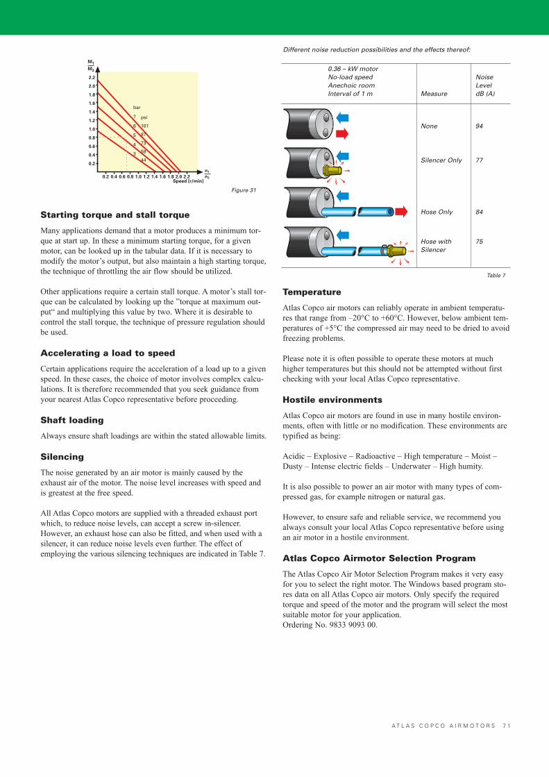
A T L A S C O P C O A I R M O T O R S 7 1
Starting torque and stall torque
Many applications demand that a motor produces a minimum tor-que at start up. In these a minimum starting torque, for a givenmotor, can be looked up in the tabular data. If it is necessary tomodify the motor�s output, but also maintain a high starting torque,the technique of throttling the air flow should be utilized.
Other applications require a certain stall torque. A motor�s stall tor-que can be calculated by looking up the �torque at maximum out-put� and multiplying this value by two. Where it is desirable tocontrol the stall torque, the technique of pressure regulation shouldbe used.
Accelerating a load to speed
Certain applications require the acceleration of a load up to a givenspeed. In these cases, the choice of motor involves complex calcu-lations. It is therefore recommended that you seek guidance fromyour nearest Atlas Copco representative before proceeding.
Shaft loading
Always ensure shaft loadings are within the stated allowable limits.
Silencing
The noise generated by an air motor is mainly caused by theexhaust air of the motor. The noise level increases with speed andis greatest at the free speed.
All Atlas Copco motors are supplied with a threaded exhaust portwhich, to reduce noise levels, can accept a screw in-silencer.However, an exhaust hose can also be fitted, and when used with asilencer, it can reduce noise levels even further. The effect ofemploying the various silencing techniques are indicated in Table 7.
Different noise reduction possibilities and the effects thereof:
Temperature
Atlas Copco air motors can reliably operate in ambient temperatu-res that range from �20°C to +60°C. However, below ambient tem-peratures of +5°C the compressed air may need to be dried to avoidfreezing problems.
Please note it is often possible to operate these motors at muchhigher temperatures but this should not be attempted without firstchecking with your local Atlas Copco representative.
Hostile environments
Atlas Copco air motors are found in use in many hostile environ-ments, often with little or no modification. These environments aretypified as being:
Acidic � Explosive � Radioactive � High temperature � Moist �Dusty � Intense electric fields � Underwater � High humity.
It is also possible to power an air motor with many types of com-pressed gas, for example nitrogen or natural gas.
However, to ensure safe and reliable service, we recommend youalways consult your local Atlas Copco representative before usingan air motor in a hostile environment.
Atlas Copco Airmotor Selection Program
The Atlas Copco Air Motor Selection Program makes it very easyfor you to select the right motor. The Windows based program sto-res data on all Atlas Copco air motors. Only specify the requiredtorque and speed of the motor and the program will select the mostsuitable motor for your application.Ordering No. 9833 9093 00.
0.36 – kW motorNo-load speed NoiseAnechoic room LevelInterval of 1 m Measure dB (A)
None 94
Silencer Only 77
Hose Only 84
Hose with 75Silencer
Table 7
2.2
2.0
1.8
1.6
1.4
1.2
1.0
0.8
0.6
0.4
0.2
Speed [r/min]
bar
7
6
5
4
3
M1
M2
0.2 0.4 0.6 0.8 1.0 1.2 1.4 1.6 1.8 2.0 2.2
psi
101
87
73
58
44
n1
n2
Figure 31
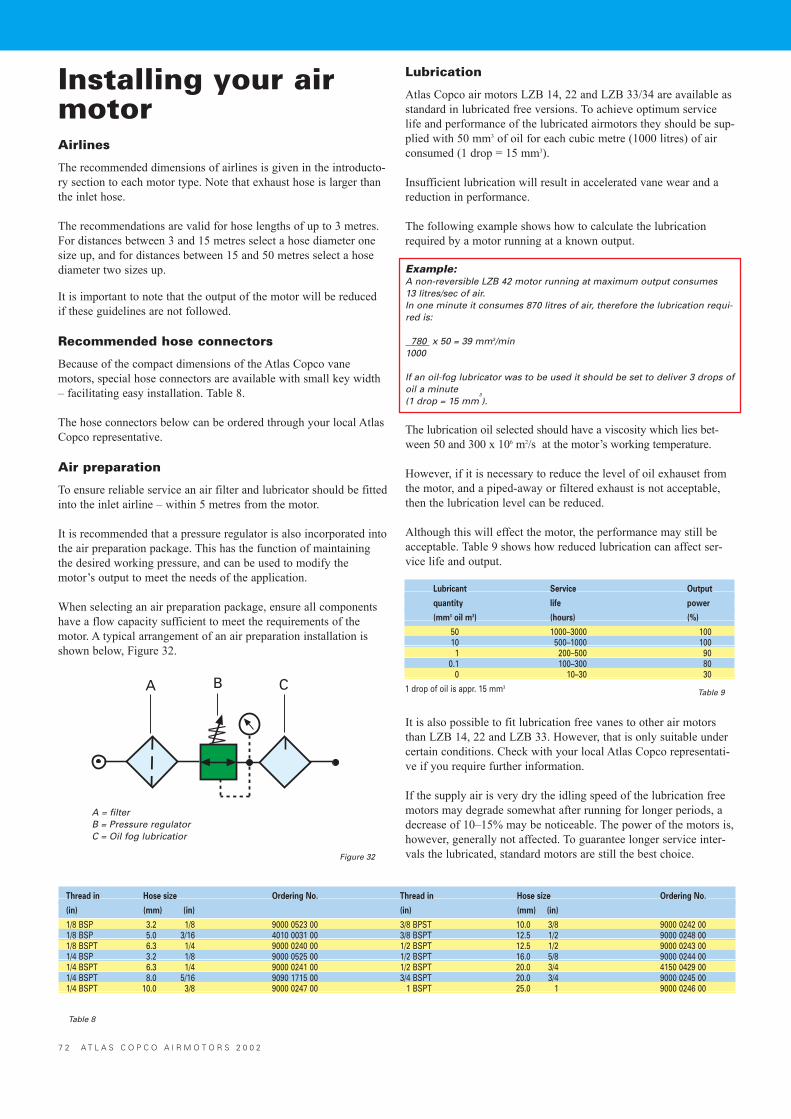
Installing your airmotorAirlines
The recommended dimensions of airlines is given in the introducto-ry section to each motor type. Note that exhaust hose is larger thanthe inlet hose.
The recommendations are valid for hose lengths of up to 3 metres.For distances between 3 and 15 metres select a hose diameter onesize up, and for distances between 15 and 50 metres select a hosediameter two sizes up.
It is important to note that the output of the motor will be reducedif these guidelines are not followed.
Recommended hose connectors
Because of the compact dimensions of the Atlas Copco vanemotors, special hose connectors are available with small key width� facilitating easy installation. Table 8.
The hose connectors below can be ordered through your local AtlasCopco representative.
Air preparation
To ensure reliable service an air filter and lubricator should be fittedinto the inlet airline � within 5 metres from the motor.
It is recommended that a pressure regulator is also incorporated intothe air preparation package. This has the function of maintainingthe desired working pressure, and can be used to modify themotor�s output to meet the needs of the application.
When selecting an air preparation package, ensure all componentshave a flow capacity sufficient to meet the requirements of themotor. A typical arrangement of an air preparation installation isshown below, Figure 32.
Lubrication
Atlas Copco air motors LZB 14, 22 and LZB 33/34 are available asstandard in lubricated free versions. To achieve optimum servicelife and performance of the lubricated airmotors they should be sup-plied with 50 mm3 of oil for each cubic metre (1000 litres) of airconsumed (1 drop = 15 mm3).
Insufficient lubrication will result in accelerated vane wear and areduction in performance.
The following example shows how to calculate the lubricationrequired by a motor running at a known output.
Example:A non-reversible LZB 42 motor running at maximum output consumes 13 litres/sec of air.In one minute it consumes 870 litres of air, therefore the lubrication requi-red is:
780 x 50 = 39 mm3/min1000
If an oil-fog lubricator was to be used it should be set to deliver 3 drops ofoil a minute (1 drop = 15 mm
3
).
The lubrication oil selected should have a viscosity which lies bet-ween 50 and 300 x 106 m2/s at the motor�s working temperature.
However, if it is necessary to reduce the level of oil exhauset fromthe motor, and a piped-away or filtered exhaust is not acceptable,then the lubrication level can be reduced.
Although this will effect the motor, the performance may still beacceptable. Table 9 shows how reduced lubrication can affect ser-vice life and output.
It is also possible to fit lubrication free vanes to other air motorsthan LZB 14, 22 and LZB 33. However, that is only suitable undercertain conditions. Check with your local Atlas Copco representati-ve if you require further information.
If the supply air is very dry the idling speed of the lubrication freemotors may degrade somewhat after running for longer periods, adecrease of 10�15% may be noticeable. The power of the motors is,however, generally not affected. To guarantee longer service inter-vals the lubricated, standard motors are still the best choice.
Thread in Hose size Ordering No. Thread in Hose size Ordering No.
(in) (mm) (in) (in) (mm) (in)
1/8 BSP 3.2 1/8 9000 0523 00 3/8 BPST 10.0 3/8 9000 0242 001/8 BSP 5.0 3/16 4010 0031 00 3/8 BSPT 12.5 1/2 9000 0248 001/8 BSPT 6.3 1/4 9000 0240 00 1/2 BSPT 12.5 1/2 9000 0243 001/4 BSP 3.2 1/8 9000 0525 00 1/2 BSPT 16.0 5/8 9000 0244 001/4 BSPT 6.3 1/4 9000 0241 00 1/2 BSPT 20.0 3/4 4150 0429 001/4 BSPT 8.0 5/16 9090 1715 00 3/4 BSPT 20.0 3/4 9000 0245 001/4 BSPT 10.0 3/8 9000 0247 00 1 BSPT 25.0 1 9000 0246 00
Table 8
Lubricant Service Output
quantity life power
(mm3 oil m3) (hours) (%)
50 1000–3000 10010 500–1000 1001 200–500 90
0.1 100–300 800 10–30 30
1 drop of oil is appr. 15 mm3
Figure 32
Table 9
7 2 A T L A S C O P C O A I R M O T O R S 2 0 0 2
A = filterB = Pressure regulatorC = Oil fog lubricatior
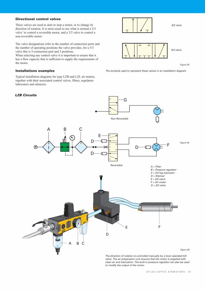
A T L A S C O P C O A I R M O T O R S 7 3
Directional control valves
These valves are used to start or stop a motor, or to change itsdirection of rotation. It is most usual to use what is termed a 5/3valve� to control a reversible motor, and a 3/2 valve to control anon-reversible motor.
The valve designations refer to the number of connection ports andthe number of operating positions the valve provides, for a 5/3valve this is 5-connection port and 3 positions. When selecting any control valve it is important to ensure that ithas a flow capacity that is sufficient to supply the requirements ofthe motor.
Installations examples
Typical installation diagrams for type LZB and LZL air motors,together with their associated control valves, filters, regulatorslubricators and silencers.
Figure 33
Figure 34
Figure 35
The symbols used to represent these valves in an installation diagram.
The direction of rotation is controlled manually by a lever-operated 5/3valve. The air preparation unit ensures that the motor is supplied withclean air and lubrication. The built-in pressure regulator can also be usedto modify the output of the motor.
A = FilterB = Pressure regulatorC = Oil fog lubricatorD = SilencerE = 5/3 valveF = Air motorG = 3/2 valve
LZB Circuits
Non-Reversible
Reversible
3/2 valve
5/3 valve
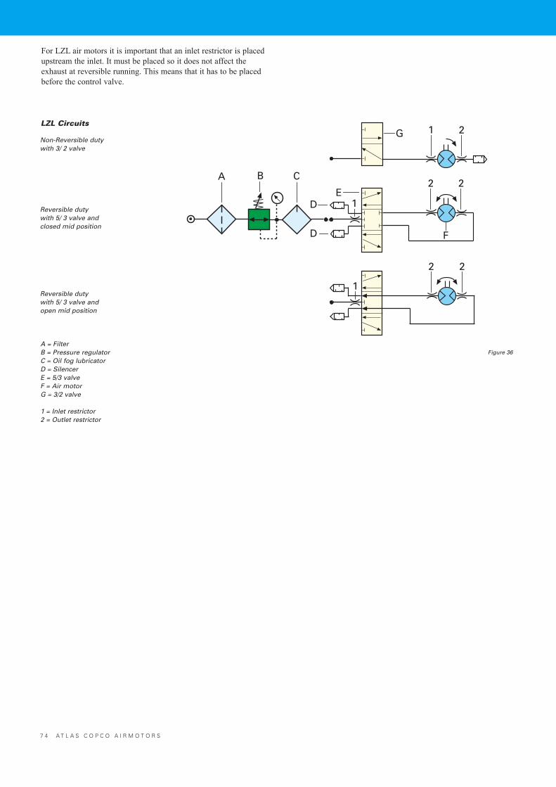
7 4 A T L A S C O P C O A I R M O T O R S
LZL Circuits
Non-Reversible dutywith 3/ 2 valve
Reversible dutywith 5/ 3 valve andclosed mid position
Reversible dutywith 5/ 3 valve andopen mid position
A = FilterB = Pressure regulatorC = Oil fog lubricatorD = SilencerE = 5/3 valveF = Air motorG = 3/2 valve
1 = Inlet restrictor2 = Outlet restrictor
For LZL air motors it is important that an inlet restrictor is placedupstream the inlet. It must be placed so it does not affect theexhaust at reversible running. This means that it has to be placedbefore the control valve.
Figure 36
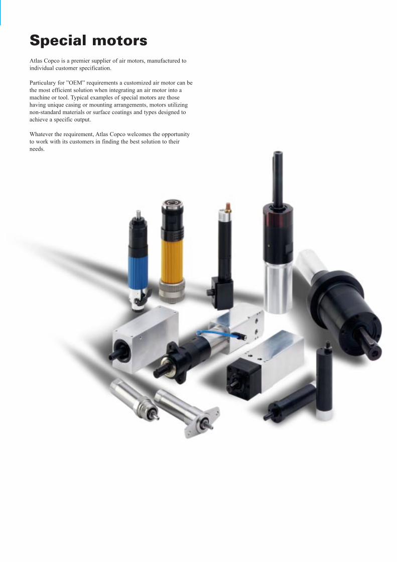
Special motorsAtlas Copco is a premier supplier of air motors, manufactured toindividual customer specification.
Particulary for �OEM� requirements a customized air motor can bethe most efficient solution when integrating an air motor into amachine or tool. Typical examples of special motors are thosehaving unique casing or mounting arrangements, motors utilizingnon-standard materials or surface coatings and types designed toachieve a specific output.
Whatever the requirement, Atlas Copco welcomes the opportunityto work with its customers in finding the best solution to theirneeds.
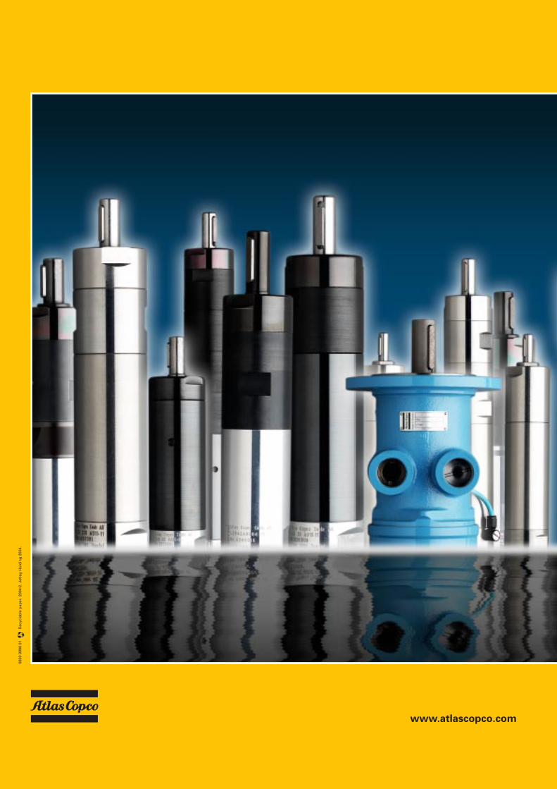
9833
899
8 01
R
ecyc
lab
le p
aper
. 200
4:2.
Jet
lag
Ho
ldin
g 2
004.
www.atlascopco.com


![[Atlas Copco] Compressed Air Manual(Bookos.org)](https://static.fdocuments.in/doc/165x107/577cc7611a28aba711a0c4b5/atlas-copco-compressed-air-manualbookosorg.jpg)

