
ATC-SDK (Sector Design Kit) User’s Guide · ATC-SDK (Sector Design Kit) User’s Guide ... This...
13
ATC-SDK (Sector Design Kit) User’s Guide Introduction Thank you for your interest in ATCsimulator2. This simple guide will assist you in understanding how the ATC- SDK is intended to be used, and how you can modify sectors to your own desires. It is assumed that you possess certain skills and understanding of navigation data, and the use of other graphic application software that will permit you to edit and create airspace for use with ATCsimulator2. Disclaimer This ATC-SDK is offered as is, and we do not offer assistance with other programs that you can use to provide data sources for the ATC-SDK. Our tech support will be limited to the ATC-SDK and any error conditions that you may encounter in its use. But, no warranty is expressed or implied as to the accuracy of the data that you are able to provide and/or modify and how this might impact game play in ATCsimulator2. There can be instances whereby the simulator may crash due to information that you have edited yourself. You are assuming all risk in the use of this ATC-SDK. We have made every attempt to trap any error condition that may arise, but as can be found in any software application, there may be something that we simply did not anticipate. But, we will explore any problem and seek to correct it in the ATC-SDK as it applies to the ATC-SDK application itself. Before You Begin Collect the data that you will need to create/edit your airspace. This includes airports, runways, navigation aids, waypoints, terminal waypoints, victor airway data, ILS marker data, approach plates, frequency information, STARS/SIDS, aircraft schedules (both civilian and commercial). All of this information will be needed to successfully create a sector that can be used with ATCsimulator2.
Transcript of ATC-SDK (Sector Design Kit) User’s Guide · ATC-SDK (Sector Design Kit) User’s Guide ... This...

ATC-SDK (Sector Design Kit) User’s Guide
Introduction Thank you for your interest in ATCsimulator2. This simple guide will assist you in understanding how the ATC-SDK is intended to be used, and how you can modify sectors to your own desires. It is assumed that you possess certain skills and understanding of navigation data, and the use of other graphic application software that will permit you to edit and create airspace for use with ATCsimulator2.
Disclaimer This ATC-SDK is offered as is, and we do not offer assistance with other programs that you can use to provide data sources for the ATC-SDK. Our tech support will be limited to the ATC-SDK and any error conditions that you may encounter in its use. But, no warranty is expressed or implied as to the accuracy of the data that you are able to provide and/or modify and how this might impact game play in ATCsimulator2. There can be instances whereby the simulator may crash due to information that you have edited yourself. You are assuming all risk in the use of this ATC-SDK. We have made every attempt to trap any error condition that may arise, but as can be found in any software application, there may be something that we simply did not anticipate. But, we will explore any problem and seek to correct it in the ATC-SDK as it applies to the ATC-SDK application itself.
Before You Begin Collect the data that you will need to create/edit your airspace. This includes airports, runways, navigation aids, waypoints, terminal waypoints, victor airway data, ILS marker data, approach plates, frequency information, STARS/SIDS, aircraft schedules (both civilian and commercial). All of this information will be needed to successfully create a sector that can be used with ATCsimulator2.

Starting The ATC-SDK As with every component of ATCsimulator2, you can start the program using; START > Programs > AEROSOFT > ATC-SDK (Sector Design Kit) The following form will appear:
Your screen may appear different, such as a white background with black range rings. This is because there have been no custom colors defined. Once a sector is loaded, you can modify the view settings and color settings to your liking. To begin editing a sector, double-click the name of the sector you wish to edit in the list on the left. You should first open a sector and look around to get an idea as to how editing a sector is accomplished.
Status Line At the bottom of the screen is a status line that will display your cursor position in X/Y coordinates (nautical miles), and the latitude/longitude equivalent as you move the cursor about the radarscope area. It also displays the distance and angle from the current cursor position, to the center of the airspace in typical 360 degrees of rotation clockwise with 360 degrees as North.

Creating A New Sector When you are ready to create a new sector, you must determine the name of the sector, the 3 or 4 letter identifier, and you must have the latitude/longitude coordinates for the main airport to be used in this sector available. This information is critical to the creation of a new sector. Once this information has been entered, the SDK will copy the folder “TEMPLATE” to the “SECTORS” folder of ATCsimulator2, using the 3 or 4 letter identifier you have provided as the new destination folder. This sector will not be usable until it passes the Analysis routine of the ATC-SDK. This will prevent using this in the simulator until it is ready.
Sequence Of Data Entry When creating a new sector, information must be entered in a certain order before additional data can be added. The list below will help guide you through the steps of creating a new sector. FIRST ELEMENT SECOND ELEMENT THIRD ELEMENT AIRPORTS RUNWAYS APPROACHES
COMMUNICATIONS TERMINAL WAYPOINTS
NAVAIDS HOLDS/AIRWAYS/ARRIVAL OR DEPARTURE ROUTES WAYPOINTS HOLDS/AIRWAYS/ARRIVAL OR DEPARTURE ROUTES TERMINAL WAYPOINTS HOLDS/AIRWAYS/ARRIVAL OR DEPARTURE ROUTES USER POINTS HOLDS/AIRWAYS/ARRIVAL OR DEPARTURE ROUTES AIRPORTS SERVED ARRIVALS or DEPARTURES TRAFFIC
Importing Graphics You can use other drawing programs such as AutoCAD to draw roads, coastlines, and video maps for NORTH, SOUTH, EAST and WEST. A template has been provided in DXF format or Drawing Interchange Format. This file can be imported into another application that supports this format. You can then draw the elements on the pre-defined layers. The layers are as follows: BORDER This layer will depict border data ROADS This layer will depict roadways COASTLINE This layer will depict coastlines NORTH This layer will depict a northern traffic flow map SOUTH This layer will depict a southern traffic flow map EAST This layer will depict a eastern traffic flow map WEST This layer will depict a western traffic flow map Layer 0 contains graphics of range rings spaced every 10 miles to 60 miles radius. You can use this as a guide to determine placement of your graphics. This layer is ignored when the data is imported into the ATC-SDK. Once you create your desired graphic objects, use the application to export the data as a DXF Release 14 format. At this time, this is the only supported import format. Note: If you create any video map for use in your sector, the only graphics that will be drawn during gameplay is what is contained in your map files. So, be sure to draw all of the content you wish to be visible during gameplay on the appropriate layer of your map.

Minimum Safe Altitude Data We are exploring a means of importing elevation data from any location on the earth. We will provide this capability in a later update. At the moment, once a new sector is created, the MSA.DAT file is created using the single MSA data you enter for the sector definition. The format of the MSA.DAT file is a grid of 156 x 156 elements of elevation data, in hundredths of feet. For instance 010 = 1000’ AGL. A sector is an area that is 60 miles radius from the central airport for the sector. This equates to a 120 x 120 nautical mile square area. The scale factored used to draw the sector is roughly 1.29 to compensate for statute miles. Thus, the data is 156 x 156. The file contains 156 rows of 156 columns of information. 010,010,012,013, etc… 010,010,012,013, etc… . .
The key to creating this data yourself is to first find the latitude/longitude origin of the sector, and then determine the elevation at every single statute mile in 78 miles in all directions from that origin. You would then store the data in integer format for each hundredths of feet.
Analyzing Your Sector Before you can use the sector you have created, you will need to run FILE > DATA > ANALYSIS. This routine will check your data and determine if it meets with minimum conditions to be usable in ATCsimulator2. If there are any problem areas, they will be denoted in RED. Some data can be denoted in red, but not prevent being used by the simulator as shown in the example below.
In the figure above, there are no coastlines or roads or holding patterns, but this itself will not prevent gameplay.

Customizing Options There are two areas that can be used to customize, color and view. By default the map area is presented as white, and each element is assigned a different color. You can customize the colors for view to better suit your desires. I prefer a black background that more closely resembles the STARS color scheme as shown in the following figure:
You can also pick and choose which items you wish to be visible when editing. This can improve redraw speed, as well as improve the view so it is less cluttered.
After A Sector Is Added Once you define a new sector, it is added to the file “APPROACH.DAT” so that it is listed on the main menu of ATCSimulator2. Once it is added, it cannot be removed using the ATC-SDK. You can however, edit the file “APPROACH.DAT” using any text editor and remove it manually. The folder however, will still remain.
Sharing Your Sector After you create a new sector, you may wish to share with your friends. To do this, simply make a zip file of the contents of the folder containing your sector. You can freely distribute this to your friends. Be sure to tell them the name and title of your sector. If you make any callsign additions or aircraft additions using the ATC-SDK,
you will also need to provide the files “master.cs” and “master.ac” to support your creation. These files are contained in the root ATCsimulator2 folder.
Use of Radio Frequencies One thing that is important is that your approach control frequency is not used by any airport within your airspace. The approach control frequency will be associated with the main airport serving the sector. Be certain this frequency is unique and not assigned to any tower of your airspace. If the frequency is used by a control tower, you will never be able to complete the transfer of communication and an error will be recorded during landing for both failing to transfer communication, and for low altitude alerts.
Latitude/Longitude number formats Latitude and longitude coordinates can be entered in a variety of ways, and unrelated databases may depict the information differently. The ATC-SDK will allow for the use of the following formats: North 36° 10’ 29.99” = N36102999 West 95° 39’ 53” = W095395300
If there is no fractional portion of the “seconds” of the coordinate, add 2 zeros at the end as is indicated in “53” or “5300” above. Also, preceed any longitude of less than 100 with a zero, as shown in “95” or “095” above.
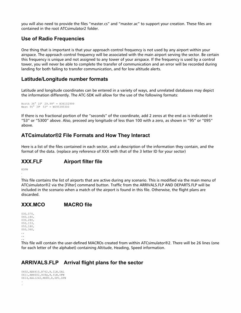
ATCsimulator®2 File Formats and How They Interact Here is a list of the files contained in each sector, and a description of the information they contain, and the format of the data. (replace any reference of XXX with that of the 3 letter ID for your sector) XXX.FLF Airport filter file KDFW . .
This file contains the list of airports that are active during any scenario. This is modified via the main menu of ATCsimulator®2 via the [Filter] command button. Traffic from the ARRIVALS.FLP AND DEPARTS.FLP will be included in the scenario when a match of the airport is found in this file. Otherwise, the flight plans are discarded. XXX.MCO MACRO file 030,070, 040,180, 030,280, 050,153, 050,180, 050,360, ,, ,, ,, This file will contain the user-defined MACROs created from within ATCsimulator®2. There will be 26 lines (one for each letter of the alphabet) containing Altitude, Heading, Speed information.
ARRIVALS.FLP Arrival flight plans for the sector 0602,ABX410,B762,R,ILN,DAL 0611,ABX602,DC8Q,R,ILN,DFW 0614,AAL1242,MD80,R,SFO,DFW . .

This file contains the arrival flight plans that are read when a scenario/timeslot is selected. The format is; Arrival time over the initial fix, Aircraft Callsign, Aircraft Type, Equipment Code, Departure Airport, Arrival Airport
DEPARTS.FLP Departure flight plans for the sector 0600,LHN606,B72Q,R,DFW,SAT 0601,LXJ220,LR60,R,DAL,ASE 0605,DAL992,B752,A,DFW,ATL . .
This file contains the departure flight plans that are read when a scenario/timeslot is selected. The format is; Departure time at the departure airport, Aircraft Callsign, Aircraft Type, Equipment Code, Departure Airport, Destination Airport
RWSTATUS.DAT Runway open/close status file. 0F2,RW17,B,O 0F2,RW35,B,O 1F9,RW17,B,O 1F9,RW35,B,O . .
This file contains the runway status for every airport in the sector. This file is modified via the [Runway] command button from the ATCsimulator®2 main menu. The format is as follows; Airport ID, Runway ID, Runway Use is [A]rrival, [D]eparture or [B]oth, Runway is either [O]pen or [C]losed
ATCS.INI Saved simulator settings on exit from the sim in ARTS-IIIa mode
Strobe,False .knbPANEL,9 .knbCOMPASS,9 .knbFIX,3 .knbALPHA,8 .knbVFR,0 . .
This file contains the positional information for list items on the scope and various other settings changed during scenario execution in ARTS mode of operation. Occasionally, some list items will disappear from view in the simulator. If you delete this file manually, it will be recreated with default position data and will restore items into view once again. These items should not be edited manually, nor does the ATC-SDK provide a way to edit them.
STARS.INI Saved simulator settings on exit from the sim in STARS mode
STROBE,False .SCALEWIDTH,92.88 .SCALEHEIGHT,-92.88 .SCALETOP,46.44 .SCALELEFT,-46.44 . .
This file contains the positional information for list items on the scope and various other settings changed during scenario execution in STARS mode of operation. Occasionally, some list items will disappear from view in the simulator. If you delete this file manually, it will be recreated with default position data and will restore items into view once again. These items should not be edited manually, nor does the ATC-SDK provide a way to edit them.
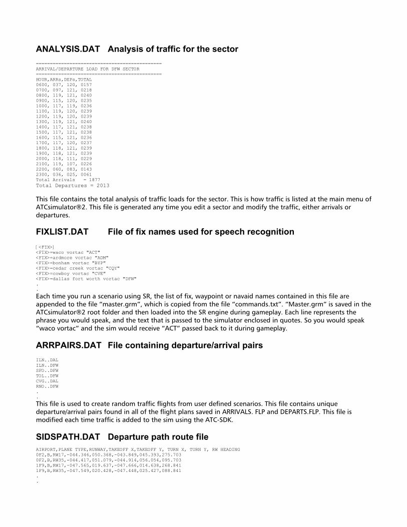
ANALYSIS.DAT Analysis of traffic for the sector ============================================= ARRIVAL/DEPARTURE LOAD FOR DFW SECTOR ============================================= HOUR,ARRs,DEPs,TOTAL 0600, 037, 120, 0157 0700, 097, 121, 0218 0800, 119, 121, 0240 0900, 115, 120, 0235 1000, 117, 119, 0236 1100, 119, 120, 0239 1200, 119, 120, 0239 1300, 119, 121, 0240 1400, 117, 121, 0238 1500, 117, 121, 0238 1600, 115, 121, 0236 1700, 117, 120, 0237 1800, 118, 121, 0239 1900, 118, 121, 0239 2000, 118, 111, 0229 2100, 119, 107, 0226 2200, 060, 083, 0143 2300, 036, 025, 0061 Total Arrivals = 1877 Total Departures = 2013 This file contains the total analysis of traffic loads for the sector. This is how traffic is listed at the main menu of ATCsimulator®2. This file is generated any time you edit a sector and modify the traffic, either arrivals or departures.
FIXLIST.DAT File of fix names used for speech recognition [<FIX>] <FIX>=waco vortac "ACT" <FIX>=ardmore vortac "ADM" <FIX>=bonham vortac "BYP" <FIX>=cedar creek vortac "CQY" <FIX>=cowboy vortac "CVE" <FIX>=dallas fort worth vortac "DFW" . .
Each time you run a scenario using SR, the list of fix, waypoint or navaid names contained in this file are appended to the file “master.grm”, which is copied from the file “commands.txt”. “Master.grm” is saved in the ATCsimulator®2 root folder and then loaded into the SR engine during gameplay. Each line represents the phrase you would speak, and the text that is passed to the simulator enclosed in quotes. So you would speak “waco vortac” and the sim would receive “ACT” passed back to it during gameplay.
ARRPAIRS.DAT File containing departure/arrival pairs ILN..DAL ILN..DFW SFO..DFW TOL..DFW CVG..DAL RNO..DFW . .
This file is used to create random traffic flights from user defined scenarios. This file contains unique departure/arrival pairs found in all of the flight plans saved in ARRIVALS. FLP and DEPARTS.FLP. This file is modified each time traffic is added to the sim using the ATC-SDK. SIDSPATH.DAT Departure path route file AIRPORT,PLANE TYPE,RUNWAY,TAKEOFF X,TAKEOFF Y, TURN X, TURN Y, RW HEADING 0F2,B,RW17,-044.346,050.368,-043.849,045.393,275.703 0F2,B,RW35,-044.417,051.079,-044.914,056.054,095.703 1F9,B,RW17,-047.565,019.637,-047.666,014.638,268.841 1F9,B,RW35,-047.549,020.428,-047.448,025.427,088.841 . .

This file is a little complicated. This information is the path to be flown once an aircraft departs the runway. A turn point is created before the aircraft flies the intended exit route from the sector. The first line contains a header of the data that follows. The PLANE TYPE element is not used at this time. The TAKEOFF X, TAKEOFF Y, TURN X, TURN Y and RW HEADING data elements are referenced as internal coordinates/angles. These values are automatically created when a runway is created/edited in the ATC-SDK. These values are stored to speed up the simulator so the translation of Lat/Long coordinates is avoided during gameplay.
AIRWAYS.DAT No longer used
AIRWAYS.TMP Airway Data File V114 ROPER FERET BYP V124 BYP MONTE PRX V15 ACT DRILL THING CQY BYP RABOO ADM V16 MQP JEN CELTC ACUFF CQY EYRIE . .
This file is used to draw airways on the sector display. The airway name is listed first, followed by the names of the fixes that make up the airway. The display of airways is controlled by the VFR MAP INTENSITY knob in ARTS mode. Deleting any fix manually in the other source files could cause a potential problem when the simulator attempts to draw the airway and the fix cannot be found.
COASTAL.DAT Graphic data for coastline information LINE,START 041.377,068.466 041.656,067.587 041.953,066.448 041.805,065.840 041.792,064.904 . .
This file contains the line information which depict coastlines. The mark of a new line is denoted with “LINE,START”, followed by a series of X, Y coordinates. The coordinate system is relative to the center of the radarscope, expressed in miles. The display of coastal information is controlled by the VIDEO MAP INTENSITY knob in ARTS mode.
ROADS.DAT Roadway line information LINE,START 034.4457,-058.7161 034.6230,-058.4902 034.6946,-058.0324 035.0636,-057.5237 . .
This file contains the line information which depict roads. The mark of a new line is denoted with “LINE,START”, followed by a series of X, Y coordinates. The coordinate system is relative to the center of the radarscope, expressed in miles. The display of roads is controlled by the VFR MAP INTENSITY knob in ARTS mode. XXXMAINE.MAP Map used for traffic that flows to/from the east XXXMAINN.MAP Map used for traffic that flows to/from the north XXXMAINW.MAP Map used for traffic that flows to/from the west XXXMAINS.MAP Map used for traffic that flows to/from the south LINE,START 4.376 , 23.02 5.56 , 22.713 LINE,START 3.624 , 18.103 3.961 , 19.324 LINE,START 4.28 , 20.494 4.586 , 21.622 . .

Each of these files will contain line information in radarscope mileage coordinates to depict line segments to the user. If there is only one video map available, regardless of traffic flow direction, it can be copied to each of the 4 file names so it is used at all times. Otherwise, 4 separate maps can be defined and saved under the appropriate filename for that flow of traffic. If VIDEO MAP is checked at the main menu of ATCsimulator®2, and a matching map for the flow direction is not found, no map information will be drawn. The display of the video map is controlled by the VIDEO MAP INTENSITY knob in ARTS mode. Creation of this data is accomplished using a program such as AutoCAD or other drafting program that can output the data as a DXF (Drawing Interchange Format) file. Creating this by hand can be accomplished, but is very time consuming. MSA.DAT See Minimum Safe Altitude Data
at the beginning of this document.
DEFINES.DAT Definitions of this sector
Airspace Name,MainAirport,AirspaceLatitude,AirspaceLongitude,RadarLatitude,RadarLongitude,MagneticVariation,MSA DALLAS/FORT WORTH INTERNATIONAL,KDFW,N32534542,W097021392,N32534542,W097021392,E0058,01000
This file contains information you entered when the sector was created. The first line is the header of the data that is to follow. This file is used to calculate mileage offsets of all related sector data.
AIRPORTS.DAT Airport Data File ICAO,Airport Name,Elevation,Latitude,Longitude,MagVar,Mapx,Mapy,Merx,Mery 0F2,BOWIE MUN,01101,N33360598,W097463202,E0090,-044.381,050.723,4942.322,2146.565 1F9,BRIDGEPORT MUN,00851,N33102872,W097494233,E0080,-047.559,019.982,4939.144,2115.824 4T6,MIDLOTHIAN/WAXAHACHIE MUN,00713,N32272195,W096544468,E0060,007.501,-031.410,4994.204,2064.433 . .
The first line of this file contains a header of the data that is to follow. Most of this information is from the data you enter using the ATC-SDK. Some elements such as the Mapx,Mapy,Merx,Mery values are calculated internally by the ATC-SDK and saved for use by the simulator during gameplay. RUNWAYS.DAT Runway Data File Airport,L RW/D RW,RW Length,RW Width,RW Elev,RW Bearing,Mapx1,Mapy1,Mapx2,Mapy2,Lat1,Long1,Lat2,Long2 0F2,RW17/RW35,03602,060,01101,1700,-044.417,051.079,-044.346,050.368,N33362372,W097463413,N33354826,W097462993 1F9,RW17/RW35,04009,060,00851,1700,-047.549,020.428,-047.565,019.637,N33105107,W097494175,N33101141,W097494272 4T6,RW18/RW36,05000,075,00686,1800,007.535,-030.921,007.467,-031.898,N32274663,W096544263,N32265727,W096544672 . .
The first line of this file contains a header of the data that is to follow. Most of this information is from the data you enter using the ATC-SDK. Some elements such as the Mapx,Mapy,Merx,Mery values are calculated internally by the ATC-SDK and saved for use by the simulator during gameplay. The RW Bearing is expressed as an integer value and is divided by 10 during gameplay. So, 1700 = 170.0 degrees. MARKERS.DAT ILS Marker Data File Airport,ID,Type,Runway,RwyX,RwyY,MkrLat,MkrLon,MkrX,MkrY,LocClass,LocCHAR,LocID,MagVar,Altitude KADS,IADS,MM,RW15,011.889,005.685,N32585518,W096503237,011.713,006.163,,,,E0058,02000 KADS,IADS,OM,RW15,011.889,005.685,N33023959,W096521390,010.018,010.631,,,,E0058,02000 KADS,ITBQ,MM,RW33,011.889,005.685,N32555355,W096491001,013.089,002.548,,,,E0058,02000 KAFW,IUPE,IM,RW16L,-016.997,007.301,N32595950,W097191652,-017.074,007.443,,,,E0058,02400 . .
The first line of this file contains a header of the data that is to follow. Most of this information is from the data you enter using the ATC-SDK. Some elements such as the RwyX,RwyY,Mkrx,Mkry values are calculated internally by the ATC-SDK and saved for use by the simulator during gameplay. The values for LocClass, LocCHAR and LocID are not currently used and reserved for a later date.

NAVAIDS.DAT Navaid Information File ID,Freq,Class,VOR Latitude,VOR Longitude,DME Ident,DME Latitude,DME Longitude,MapX,Mapy,Merx,Mery,VOR Name ACT,11530,VT,N31394440,W097160850,,N31394440,W097160850,-013.935,-087.707,4972.768,2008.135,WACO ADM,11670,VT,N34124165,W097100597,,N34124165,W097100597,-007.882,094.895,4978.821,2190.737,ARDMORE BYP,11460,VT,N33321495,W096140274,,N33321495,W096140274,048.273,046.093,5034.976,2141.935,BONHAM . .
The first line of this file contains a header of the data that is to follow. Most of this information is from the data you enter using the ATC-SDK. Some elements such as the Mapx,Mapy,Merx,Mery values are calculated internally by the ATC-SDK and saved for use by the simulator during gameplay. As you can see the DME Ident feature is blank, and not currently used by the sim, but reserved for a later date.
TERM_WPS.DAT Terminal Waypoint Data File Location,ID,Type,Latitude,Longitude,MagVar,Mapx,Mapy,Merx,Mery KGVT,CD17,ICF,N33150130,W096074127,E0052,054.642,025.422,5041.345,2121.264 KGVT,CF17,ICF,N33161998,W096034049,E0051,058.662,026.993,5045.365,2122.835 KGVT,CLYDE,RAF,N33101413,W096055576,E0052,056.404,019.691,5043.107,2115.533 KGVT,MAJOR,O F,N33092261,W096034870,E0051,058.525,018.664,5045.228,2114.506 . .
The first line of this file contains a header of the data that is to follow. Most of this information is from the data you enter using the ATC-SDK. Some elements such as the Mapx,Mapy,Merx,Mery values are calculated internally by the ATC-SDK and saved for use by the simulator during gameplay. WAYPOINTS.DAT Waypoint/Fix Data File ID,Type,Usage,Latitude,Longitude,MagVar,Mapx,Mapy,Merx,Mery ACKME,RFE,B,N33505124,W097404027,E0061,-038.508,068.494,4948.195,2164.336 ACUFF,R,L,N32105342,W096363903,E0055,025.627,-050.940,5012.330,2044.902 ADDMO,CAF,L,N34135887,W096555627,E0057,006.305,096.454,4993.008,2192.296 ADEMS,RFE,L,N32271350,W096445625,E0056,017.326,-031.577,5004.028,2064.265 . .
The first line of this file contains a header of the data that is to follow. Most of this information is from the data you enter using the ATC-SDK. Some elements such as the Mapx,Mapy,Merx,Mery values are calculated internally by the ATC-SDK and saved for use by the simulator during gameplay. USERPNTS.DAT User-defined Waypoint Data File WP01,042.340,026.644 WP02,026.644,039.966 WP03,026.644,040.098 WP04,-025.985,040.230 . .
These points are created by the user, and no lat/long coordinate pairs are saved with the information. They are used to help guide the aircraft along a particular route, and are not displayed on the radarscope during gameplay. Create these points to create custom paths that you wish for the aircraft to follow. APSERVED.DAT Directional Airport Reference Data File 517 BPT,SE GGG,E SRR,W LBB,W HOU,SE . . .
This file contains a reference to the cardinal direction of the destination/departure airports from the center of the radarscope. The first line entry is the number of airports referenced in the file. That is followed by the AIRPORT ID, DIRECTION from the center of the radarscope. This file is used to build arrival and departure flight paths that put the aircraft on a course that resembles reality. For instance, any aircraft flying out of your sector going to BPT, will leave via the route defined for a Southeasterly (SE) direction. If at a later date, you wanted

BPT traffic to exit to the north, simply change SE to N. The same rule applies for arrivals; any aircraft coming from BPT will enter from the route defined for a SE approach. ENTRY.DAT Entry Route Data File P NE 2 ZFW 127.45 WP01 060 NA MANOS NA NA J NE 2 ZFW 127.45 WP02 130 NA CARBS NA NA . .
This file is used to store the routes that aircraft will fly when entering the sector. There will be a total of 16 entry paths for either [J]et or [P]rop aircraft. The format for each route is as follows; “P NE 2 ZFW 127.45”
This is a “Prop” or “P” route from the “NE” with “2” fixes, and the connecting center facility is “ZFW” on “127.45” The route points are; The first point is “WP01” with an altitude crossing restriction of “060” and NO speed restriction, shown as “NA” The second point is “MANOS” with no altitude or speed restriction, indicated by “NA” for both. EXIT.DAT Exit Route Data File P NE 1 ZFW 127.45 WP17 100 NA J NE 1 ZFW 127.45 WP18 170 NA . .
This file is used to store the routes that aircraft will fly when leaving the sector. There will be a total of 16 exit paths for either [J]et or [P]rop aircraft. The format for each route is as follows; “P NE 1 ZFW 127.45”
This is a “Prop” or “P” route that will exit to the “NE” with “1” fix, and the connecting center facility is “ZFW” on “127.45” The only point in the route is; “WP17” with an exit altitude of “100” and no speed restriction.
NAMES.DAT No Longer Used
FREQ.DAT Communication Frequency Data File 4T6,APP,0012520 4T6,DEP,0012520 4T6,TWR,0012520 . .
This file contains the frequency information for each airport in the sector. Each line will contain the airport name, facility control position, and frequency expressed as the true frequency * 100. APP=Approach Control, DEP=Departure Control, TWR = Tower Control. NO TWR should have the same frequency assigned as that used by the main airport of the sector. For instance, DFW’s main APP frequency is “125.0”. Meaning, “125.0” is reserved for use by approach control at DFW only! If you have a TWR with that frequency, you can never transfer communication to the tower, which will result in a handoff error.

HOLDS.DAT Holding Pattern Data File FIXID,Inbound,TurnDir,Length,Time,MinAlt,MaxAlt,Speed ACKME,1950,R, ,10, ,17999, BRIAN,3080,R, ,10, ,17999, CHECK,0160,R, ,10, ,17999, . .
This file is used for published holding pattern information. The Length, MinAlt, and Speed settings are not currently used by the simulator, and reserved for future use.
LOCALIZER.DAT No Longer Used
USABLE.DAT Control File True or False
This file controls whether or not the simulator can use the sector. If all tests are passed, “True” will be recorded here. If there is something not quite right with the data for this sector, “False” is recorded. To override this setting, edit with NOTEPAD and save “True” in this file. This will then force the sector to be usable by the simulator. Some sectors that ship with the product will fail the analysis due to issues that are not important to gameplay, such as missing frequencies at airports that do not have any traffic to/from them. So, overriding this setting would be acceptable in that situation. But, in doing so, you are telling the simulator that everything is okay. Should there be something wrong with the data, it could result in crashing of the simulator, so beware. How Routes Are Constructed When flight plans are loaded into the simulator, a few things are taken into account; #1, the type of aircraft, is it a Jet or a Prop? #2, the departure or destination airport, from/to which direction from the area? So, here is what happens. Using the flight plan of the aircraft, read the departure/destination airport pair. Using the destination airport, open the “APSERVED.DAT” file and retrieve the arrival or exit direction. Now, with the direction recorded, open the ENTRY.DAT or EXIT.DAT and retrieve the route information for this particular type of flight, and aircraft type. Now, piece together the route segments forming the arrival/departure path of the aircraft and add it to the queue of aircraft in the arrival/departure tab list. Editing Aircraft Callsigns Be aware that adding/changing callsigns to the program will result in the REAL pilot voices failing to speak the changes. The REAL option provides for prerecorded pilot phrases to match the existing callsigns. Once you add something new, there is no recorded phrase that will match it. Your only choice is to then use the SYNTHETIC pilot voice; it can speak everything contained in the callsign file.
Tech Support For any problem related to the application, please send an email to [email protected] explaining the nature of the error, and possibly provide a copy of the sector you are editing when the error occurs. We will work promptly to correct the problem.