
ATC “NITTA CHANGE SYSTEM” “XC60” · PDF fileatc “nitta change...
32
ATC “NITTA CHANGE SYSTEM” “XC60” USERS GUIDE MAINTENANCE & INSTRUCTION MANUAL Nitta Corporation BUSINESS DEVELOPMENT CENTER MECHATRONICS SYSTEMS DEPT.
Transcript of ATC “NITTA CHANGE SYSTEM” “XC60” · PDF fileatc “nitta change...
ATC “NITTA CHANGE SYSTEM”
“XC60”
USERS GUIDE MAINTENANCE & INSTRUCTION
MANUAL
Nitta Corporation BUSINESS DEVELOPMENT CENTER MECHATRONICS SYSTEMS DEPT.

- - 1
CONTENTS PRECAUTIONARY NOTES ・・・・・・・・・・・・ 3 1.EQUIPMENT DESCRIPTION ··············································································································································· 4
1-1 Robot side ···································································································································································· 4 1-1-1 Robot Adaptor ························································································································································· 4 1-1-2 Robot Adaptor Plate (OPTION) ···························································································································· 5 1-2 Tool Side······································································································································································ 5 1-2-1 Tooling Adaptor······················································································································································· 5 1-2-2 Tooling Adaptor Plate (OPTION)·························································································································· 5 1-3 Option ··········································································································································································· 5
2.COMPONENTS ······················································································································································· 6 3.STANDARD SPECIFICATION········································································································ 7
3-1 XC60 Main Body specification.································································································································· 7 3-2 Chucking sensor specification····································································································································· 8 3-2-1 Ace contact sensor ··················································································································································· 8 3-2-2 Chuck /Unchuck lead switch·································································································································· 9 3-3 Load Allowance and Installation Notes ·················································································································· 10 3-4 Power Load Allowance ············································································································································· 10
4.IDENTIFYING THE XC60·············································································································· 11 5.INSTALLATION ············································································································································· 12
5-1 Robot Adaptor···························································································································································· 12 5-2 Tooling Adaptor························································································································································· 12 5-3 Chuck/Unchuck Port Connections ···························································································································· 13 5-4 Wiring ········································································································································································· 13 5-5 User Air Connections················································································································································ 13 5-6 Cable Settlement ························································································································································ 13 5-7 Tool Changer Installing Considerations··················································································································· 14 5-7-1 Tool Changer Application····································································································································· 14 5-7-2 Tool Changer Surroundings ·································································································································· 14 5-7-3 I-mark ····································································································································································· 14
6.OPERATION AND PROGRAMMING ·························································································· 15
6-1 Operation and Programming ····································································································································· 15 6-2 Basic Flow of The NITTA CHANGE SYSTEM·································································································· 15 6-3 NITTA CHANGE SYSTEM Interlocks ·················································································································· 16 6-4 Operation Considerations··········································································································································· 16 6-5 Emergency ·································································································································································· 18 6-5-1 Manual Separation of XC60 ································································································································ 18 6-5-2 Collision or Interference Managements ··············································································································· 19 6-5-3 Water splashing treatment····································································································································· 19 6-6 Attention in the usage of servo motor in the tool side ···················································································· 19
- - 2
7.INSPECTION AND MAINTENANCE ······················································································ 20 7-1 Inspection and Maintenance Schedule ····················································································································· 20 7-2 Inspection Spots ························································································································································· 21 7-3 Maintenance outlines ················································································································································· 22 7-3-1 Lubrication on the XC60 Body··························································································································· 22 7-3-2 Replacing electrical contacts of the Tooling Adaptor ······················································································· 22 7-3-3 Replacing O-Rings of the Air Port····················································································································· 23 7-3-4 Checking Chucking Sensor··································································································································· 24 7-3-5 Replacing Tapered Pin·········································································································································· 24 7-3-6 Replacing Locating Bushings ······························································································································· 25 7-3-7 Replacing Tooling Adaptor Lock-pins ················································································································ 25
8.SPARE PARTS ················································································································································· 26 9.BACK UP SYSTEM······································································································································ 26 10.TROUBLE SHOOTING·························································································································· 27
10-1 Trouble Factors (Cause Chart) ·································································································································· 27 10-2 Trouble phenomena and shooting······························································································································ 27 10-2-1 The NITTA CHANGE SYSTEM does not work.····························································································· 27 10-2-2 The NITTA CHANGE SYSTEM can not exchange signals ··········································································· 29 10-2-3 The NITTA CHANGE SYSTEM has air leakage····························································································· 30 10-2-4 The NITTA CHANGE SYSTEM gets heat ······································································································· 30 10-2-5 Tool (Gun, Hand, etc.) does not work ··············································································································· 30
REFERENCE DRAWINGS

- - 3
PRECAUTIONARY NOTES
The use of this document is reserved exclusively for the use of Nitta Corporation (hereinafter “the Corporation”) customers and personnel. The information and drawings contained herein are the sole property of the Corporation, and shall not be divulged to any third party without the prior written consent of the Corporation. The Corporation makes no warranty of any kind with regard to this user's guide, including, but not limited to, implied warranties or fitness for a particular purpose. The Corporation shall not be liable for any errors contained herein or for incidental or consequential damages in connection with the performance or use of this user's guide. This manual contains all the information about XC60 for proper operation and maintenance. Please, make sure that all the personnel read and understand this manual thoroughly before using the NITTA CHANGE SYSTEM XC60 system, and certainly hand this manual to the person who operates this system. Please, check the inside of packages, and make sure about next 2 items are inside of the shipment.
1. Installing bolts 2. Preliminary parts (depending on special arrangement)
We carefully pack our shipments. But, unfortunately you find any missing parts, please contact with our offices on the cover of this manual. Thank you for choosing our NITTA CHANGE SYSTEM.

- - 4
1.EQUIPMENT DESCRIPTION The NITTA CHANGE SYSTEM is the pneumatic auto-tool exchanger. It is made up of two parts : a Robot Adaptor and a Tooling Adaptor. The system can be attached to any tooling by a optional adaptor plate, and also equips chucking mechanisms such as connecting pins and air ports. 1-1 Robot side 1-1-1 Robot Adaptor The Robot Adaptor is the basic part of the NITTA CHANGE SYSTEM. This adaptor equips the sensor, which indicates the state of chucking mechanisms. This sensor outputs “CHUCK”, “UNCHUCK” and “FACE” signals. [Chucking Mechanism]
The Robot Adaptor and the Tool Adaptor are connected each other by cams. These cams have special mechanism, which automatically adjusts for any dimensional error that may occur during chucking. These cams are driven by air cylinders, and designed so that they will not release even if the units is subjected to more than its rated load capacity. If an extreme load is applied, the chucking surfaces of both the robot and tooling adaptors separate slightly but never release. And the springs extend air cylinders provide fale-safe mechanism which avoids falling the tooling adaptor off even if the units looses its air pressure accidentally. [Chucking Sensing Signals]
・Chuck complete signal(CHUCK) This signal indicates that the cams of both adaptors are completely chucked. That is, it indicates that the robot can move the Tooling Adaptor from the tool storage fixture.
・Cam released signal(UNCHUCK)
This signal indicates that the locking cam is retracted in the Robot Adaptor. That is, it indicates that the cams are at the proper position to allow the Robot Adaptor to approach or unchuck the Tooling Adaptor.
・Face contact(FACE)
This signal indicates that the faces of both adaptors are in contact each other. That is, it indicates that the chucking surfaces of both adaptors are properly contacted, so that the cams can be brought into engagement.
[Chucking mechanism]
Six air connection ports and fifteen electrical signal contacts are provided in the NITTA CHANGE SYSTEM XC60.
- - 5
1-1-2 Robot Adaptor Plate (OPTION) The Robot Adaptor plate allows the mating of the Robot Adaptor unit to your robot. Nitta Corporation can provide the Robot Adaptor plate, or you can provide your own Robot Adaptor plate.
Refer to the Reference Drawings at the back of this manual for details on the bolt drilling locations.
1-2 Tool Side 1-2-1 Tooling Adaptor
The Tooling Adaptor is another basic part of the NITTA CHANGE SYSTEM and allows your tools to be attached. The locking cams of the Robot Adaptor will be engaged to the lock pins of this adaptor.
1-2-2 Tooling Adaptor Plate (OPTION)
The Tooling Adaptor plate allows the mating of the Tooling Adaptor unit and your tools. Like the Robot Adaptor plate, Nitta Corporation can provide the Tooling Adaptor plate, or you can provide your own Tooling Adaptor plate.
Refer to the Reference Drawing at the back of this manual for details on the bolt drilling locations.
1-3 Option
Please ask us about the details of non-standard options such as signal-pin module, electric module and pneumatic module.

- - 6
2.COMPONENTS
This system is composed of the XC60 Body and the signal-pin Assembly. This assembly consists of fifteen electrical signal contacts with spring contact pin.
Fig. 1 System
Robot Adaptor
Tooling Adaptor
Tooling Adaptor Plate
Cap Bolt
Robot
Cap Bolt(M8×45)
Cap Bolt(M8×40)
Cap Bolt
Cap Bolt(M10)
- - 7
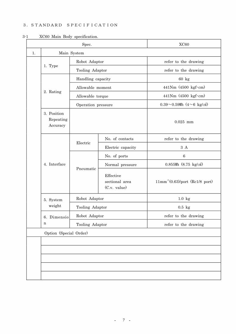
3.STANDARD SPECIFICATION 3-1 XC60 Main Body specification.
Spec. XC60
1. Main System
Robot Adaptor refer to the drawing 1. Type
Tooling Adaptor refer to the drawing
Handling capacity 60 kg
Allowable moment 441Nm (4500 kgf・cm)
Allowable torque 441Nm (4500 kgf・cm) 2. Rating
Operation pressure 0.39~0.59 (4~6 kg/)
3. Position Repeating Accuracy
0.025 mm
No. of contacts refer to the drawing Electric
Electric capacity 3 A
No. of ports 6
Normal pressure 0.855 (8.75 kg/) 4. Interface Pneumatic
Effective sectional area (C.v. value)
11mm2(0.63)/port (Rc1/8 port)
Robot Adaptor 1.0 kg 5. System weight Tooling Adaptor 0.5 kg
Robot Adaptor refer to the drawing
6. Dimension Tooling Adaptor refer to the drawing
Option (Special Order)
- - 8
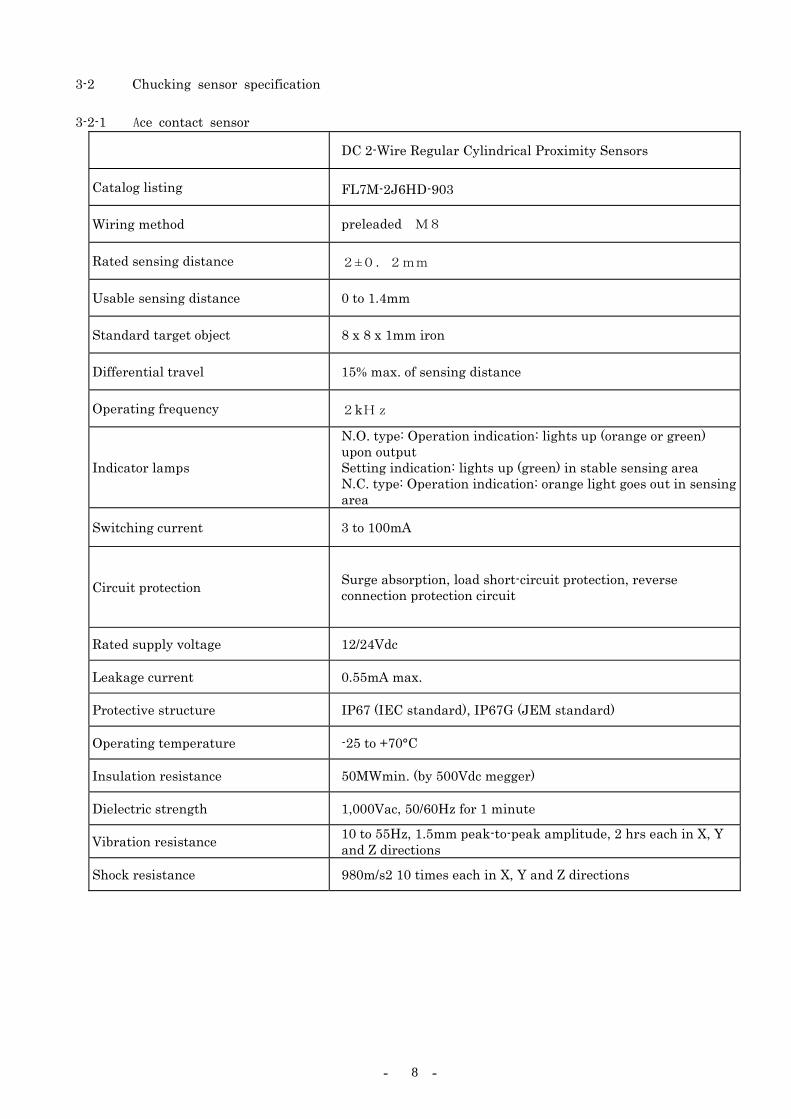
3-2 Chucking sensor specification 3-2-1 Ace contact sensor
DC 2-Wire Regular Cylindrical Proximity Sensors
Catalog listing FL7M-2J6HD-903
Wiring method preleaded M8
Rated sensing distance 2±0.2mm
Usable sensing distance 0 to 1.4mm
Standard target object 8 x 8 x 1mm iron
Differential travel 15% max. of sensing distance
Operating frequency 2kHz
Indicator lamps
N.O. type: Operation indication: lights up (orange or green) upon output Setting indication: lights up (green) in stable sensing area N.C. type: Operation indication: orange light goes out in sensing area
Switching current 3 to 100mA
Circuit protection Surge absorption, load short-circuit protection, reverse connection protection circuit
Rated supply voltage 12/24Vdc
Leakage current 0.55mA max.
Protective structure IP67 (IEC standard), IP67G (JEM standard)
Operating temperature -25 to +70°C
Insulation resistance 50MWmin. (by 500Vdc megger)
Dielectric strength 1,000Vac, 50/60Hz for 1 minute
Vibration resistance 10 to 55Hz, 1.5mm peak-to-peak amplitude, 2 hrs each in X, Y and Z directions
Shock resistance 980m/s2 10 times each in X, Y and Z directions
- - 9
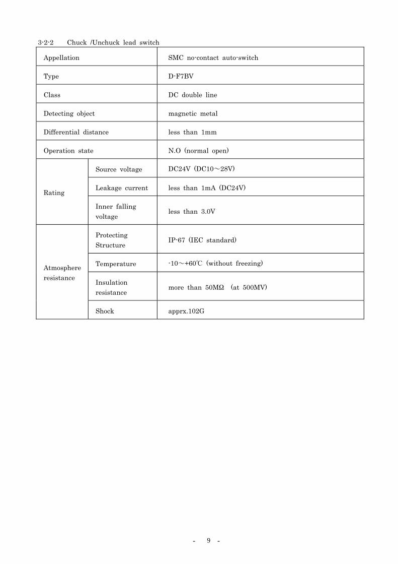
3-2-2 Chuck /Unchuck lead switch
Appellation SMC no-contact auto-switch
Type D-F7BV
Class DC double line
Detecting object magnetic metal
Differential distance less than 1mm
Operation state N.O (normal open)
Source voltage DC24V (DC10~28V)
Leakage current less than 1mA (DC24V) Rating
Inner falling voltage
less than 3.0V
Protecting Structure
IP-67 (IEC standard)
Temperature -10~+60 (without freezing)
Insulation resistance
more than 50MΩ (at 500MV)
Atmosphere resistance
Shock apprx.102G

- - 10
3-3 Load Allowance and Installation Notes The specified rating load, moment and torque of NITTA CHANGE SYSTEM XC60 expresses the active state after the system is installed on a robot. The system should be setted with consideration of inertia and acceleration generated by movements of the robot, so that the maximum load of normal operation will never be over those ratings. The rating load, moment and torque are explained on figure 2.
carrying load W = 60kg
eccentricity L = 22 ltlm +
allowable bending moment M = L×W×GR (note)
= 10050
×60×9.8×1.5≦441 N・m 4500kgf・cm
allowable twisting torque T = 1t×W×GR (note)
= 10050
×60×9.8×1.5≦441 N・m 4500kgf・cm
(note) GR represents the acceleration of the Robot at normal motion in automatic operations. GR value of a robot will be different on each other. Please refer to the manufacture of your robots about the precise GR value.(Generally, GR is sited between 1.5 to 2.0G)
Fig. 2 Definition of load rating 3-4 Power Load Allowance
The NITTA CHANGE SYSTEM XC60 can carry 15A of the maximum current in all, when it has the standard signal-pin assembly (15 connecting pins). And it can carry 3A, 110V per pin. However, the current over 3A should not be applied on adjacent pins at the same time when the plural numbers of user signal pins are used.
1 00
8 0
6 0
4 0
2 0
2 0 4 0 6 0 8 0 1 0 0
l m ( c m)
6 0
W= 6 0 k g
W= 3 0 k g
- - 11
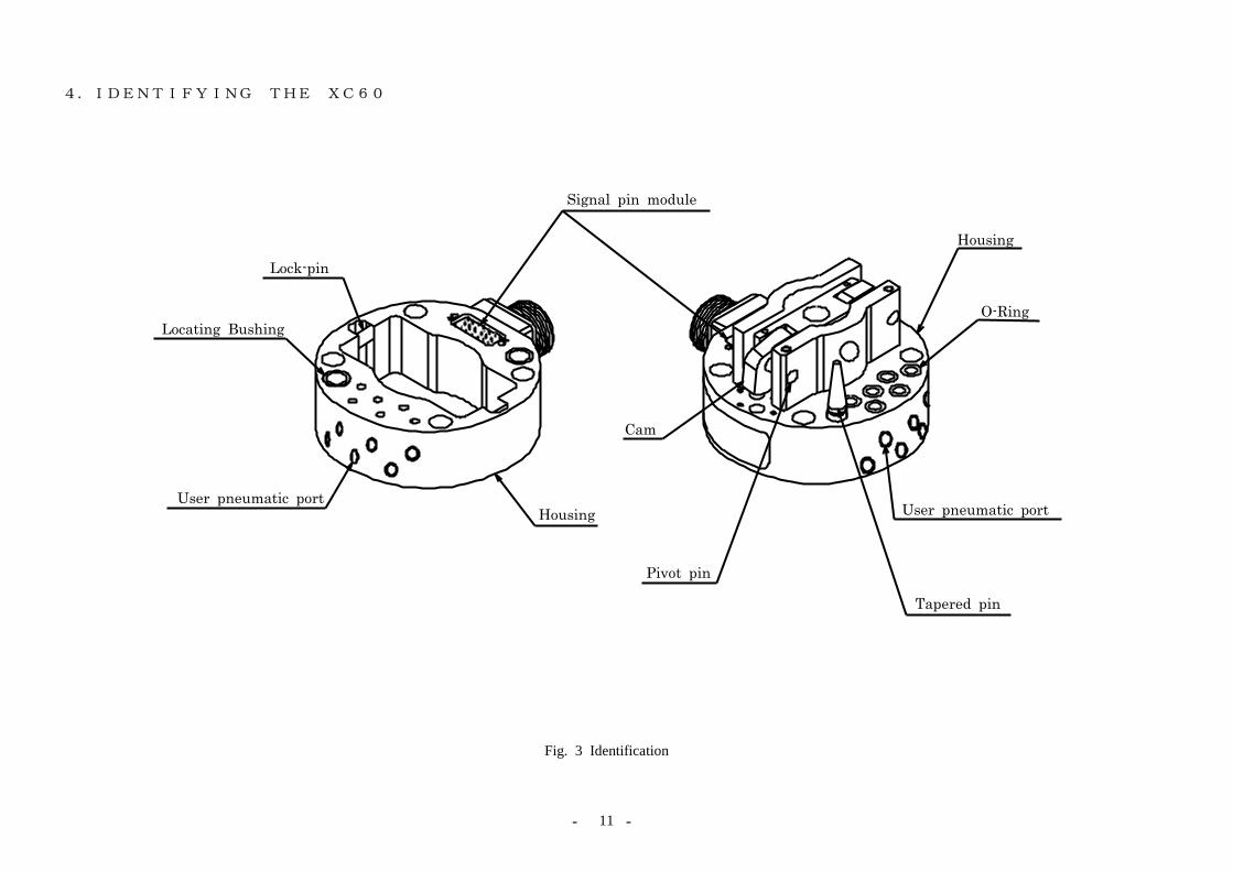
4.IDENTIFYING THE XC60
Fig. 3 Identification
Locating Bushing
Housing
Lock-pin
Signal pin module
Pivot pin
Cam
Tapered pin
HousingUser pneumatic port
User pneumatic port
O-Ring

- - 12
5.INSTALLATION 5-1 Robot Adaptor
The Robot Adaptor is composed of the Robot Adaptor Body and the Adaptor Plate. To install the Robot Adaptor to your robot, remove the Robot Adaptor Plate from the Robot Adaptor Body, first. Next, machine mating holes in the Robot Adaptor Plate. And then, attach the plate to your robot. Last, attach the Robot Adaptor Body to the Adaptor Plate by four bolts.
(Refer to fig.1) × 4 Installation Bolts M8 length 50mm (※ tighten with the plain and spring washers)
5-2 Tooling Adaptor
The Tooling Adaptor is also composed of the Tooling Adaptor Body and the Tooling Adaptor Plate. To install the Tooling Adaptor, remove the Tooling Adaptor Plate from the Tooling Adaptor Body. And machine mating holes in the Tooling Adaptor Plate. Then, attach the plate to the Tooling Adaptor. (Refer to fig.1)
× 4 Installation Bolts M8 length 45mm (※ tighten with the plain and spring washers)
>>>>>>>>>>>>>>>>>>>>>>CAUTION<<<<<<<<<<<<<<<<<<<<<<
・EVEN IF A REMOVING OF THE ADAPTOR PLATE FROM THE ADAPTOR BODY IS NOT NECESSARRY FOR INSTALLATION, UNSCREW THE INSTALLING BOLTS AND APPLY A COAT OF THE LOCKTIGHT ON THE BOLTS BEFORE TIGHTENING THEM ON THE BODY AGAIN. MAKE SURE THIS PROCESSES BECAUSE THE INSTALLING BOLTS ARE NOT COMPLETELY TIGHTENED WHEN THE SYSTEM IS SHIPPED.
・BE SURE TO COUNTERSINK THE SCREW HOLES DEEP ENOUGH SO THAT THE MOUNTING SCREWS WILL NOT PROJECT BEYOND THE ADAPTOR PLATE SURFACE.
>>>>>>>>>>>>>>>>>>>>>>>>>><<<<<<<<<<<<<<<<<<<<<<<<<

- - 13
5-3 Chuck/Unchuck Port Connections Plumb a single solenoid four-way air valve to the chucking mechanism ports labeled “CHUCK” and “UNCHUCK.” Be sure to plumb the normally pressurized line (solenoid de-energized) to the port labeled “CHUCK” so that the chucking mechanism will remain in the chucked state in the event of a power failure. >>>>>>>>>>>>>>>>>>>>>>CAUTION<<<<<<<<<<<<<<<<<<<<<<
Don’t plumb into UNCHUCK port if it doesn’t necessary to change tool side (if robot side and tool side are always coupled together). Please keep the air pressure into CHUCK port all the time under the above condition.
>>>>>>>>>>>>>>>>>>>>>>>>>><<<<<<<<<<<<<<<<<<<<<<<<< 5-4 Wiring
Refer to the appropriate electrical schematic in the Reference Drawings section of this manual and wire your robot inputs and outputs as required by your application through the electrical connector mounted on the contact block mounted on the body of the Robot Adaptor. Be sure to incorporate the NITTA CHANGE SYSTEM internal sensors within your robot (line, etc.) control program. These signals can be accessed at the electrical connector mentioned above.
5-5 User Air Connections
Plumb your air lines as required by your tool (Material Handling Apparatus, welding, guns, etc.) application to the ports on the Robot Adaptor Body. These ports on are provided as part of the standard specification on the Robot Adaptor unit.
>>>>>>>>>>>>>>>>>>>>>>CAUTION<<<<<<<<<<<<<<<<<<<<<<
・ TOOL CHANGER AIR CONNECTIONS. PLEASE, PLUMB AIR LINES WITH A CONNECTION OF AIR VALVES WHICH IS NOT ALLOWING THE AIR FLOW INTO“UNCHUCK”PORTS WHEN A POWER FAILURE OF THE AIR VALVE OCCURS, EVETHOUGH THE TOOL CHANGER IS PROVIDED WITH A FAIL-SAFE MECHANISM WHICH PREVENTS A FALLING OFF OF THE TOOL EVEN IF THE PRESSURE OF AIR LINE IS UNEXPECTEDLY LOST.
>>>>>>>>>>>>>>>>>>>>>>>>>><<<<<<<<<<<<<<<<<<<<<<<<< 5-6 Cable Settlement
Damage of connectors or electric module, or breakage of wires may occur when a extreme force of stress is applied. Fix the cables of robot side at a place around the connector of the Robot Adaptor by using spiral tubes or bands, etc. Make sure that a excessive force is not applied on the cables or hoses during your robot is rotating its hand. An example of fixing cable with brackets is showing on figure 4.
Fig.4 An example of cable fixation
- - 14
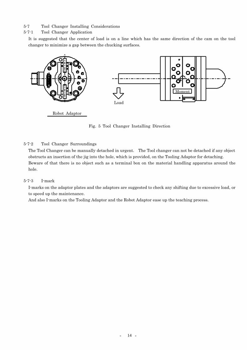
5-7 Tool Changer Installing Considerations 5-7-1 Tool Changer Application
It is suggested that the center of load is on a line which has the same direction of the cam on the tool changer to minimize a gap between the chucking surfaces.
Fig. 5 Tool Changer Installing Direction 5-7-2 Tool Changer Surroundings
The Tool Changer can be manually detached in urgent. The Tool changer can not be detached if any object obstructs an insertion of the jig into the hole, which is provided, on the Tooling Adaptor for detaching. Beware of that there is no object such as a terminal box on the material handling apparatus around the hole.
5-7-3 I-mark
I-marks on the adaptor plates and the adaptors are suggested to check any shifting due to excessive load, or to speed up the maintenance. And also I-marks on the Tooling Adaptor and the Robot Adaptor ease up the teaching process.
Load
Robot Adaptor
Moment

- - 15
6.OPERATION AND PROGRAMMING 6-1 Operation and Programming
This chapter shows the example of the interlock signals surrounding the XC60. Exchanging signals, which synchronize the robot with surrounding systems or confirm movements of the robot are necessary to maintain reliance and safety on the XC60. The XC60 has three sensors for detecting movements of itself. Refer to “1.EQUIPMENT DESCRIPTION” for details.
6-2 Basic Flow of The NITTA CHANGE SYSTEM Please adjust the interlocks of your robot with referring to this flow chart Indicates processing condition.
Input Robot Output External Input
XC60 Chucking Sensor controlling
solenoid valve Fixture
Limit switch Robot motion Face Chuck Unchuck Chuck Unchuck Tool side
C
H
U
C
K
I
N
G
Waiting position ↓
Moving ↓
Near by chucking position ↓
Approaching ↓
Chucking position ↓
Chuck ↓
Chucking completion ↓
Moving ↓
Working
OFF ↓
↓
↓
ON
↓
↓
↓
↓
OFF ↓
↓
↓
↓
ON
↓
↓
↓
ON ↓
↓
↓
↓
OFF
↓
↓
↓
OFF ↓ ↓ ↓ ↓
ON ↓ ↓ ↓
ON ↓ ↓ ↓ ↓
OFF ↓ ↓ ↓
ON ↓
↓
↓
↓
↓
↓
OFF ↓
U
N
C
H
U
C
K
I
N
G
Working
↓
Moving
↓
Unchuck position
↓
Unchuck
↓
Leaving
↓
Near by unchucking position
↓
Moving
↓
Waiting
ON
↓
↓
↓
OFF
↓
↓
↓
ON
↓
↓
OFF
↓
↓
↓
↓
OFF
↓
↓
ON
↓
↓
↓
↓
ON
↓
↓
OFF
↓
↓
↓
↓
OFF
↓
↓
ON
↓
↓
↓
↓
OFF
↓
ON
↓
↓
↓
↓
↓
During Robot is working, condition the signal as “Face ON.”

- - 16
6-3 NITTA CHANGE SYSTEM Interlocks Setting next four signals are suggested for safe and smooth operation of the Tool Changer.
1) Low Pneumatic Detection Signal
This is a signal, which warns lost of the Tool Changer pneumatics. It stops a manner of the robot when the signal is off.
2) Tool existence detection signal
This is a signal, which detects existence of the tools on the Tool Storage Fixture. This Interlock signal allows the Unchuck valve open only when all the tools are on the Fixture. So, it prevents falling off of the tools for the event of unexpected situation.
3) Tool Number Identification Signal
This is a signal, which checks the matching between the equipped tool and its programmed number. So, the signal is useful when several robots chuck with the Material Handling apparatus from the same Tool Storage Fixture.
4) Tool changer Manner Indication Lamp
Setting lamps, which indicate the ON/OFF state of signal such as the Chuck, Unchuck, Face, or User signal, are suggested for understanding condition of the system for trouble detection.
6-4 Operation Considerations The Tool Changer requires that the chucking surfaces of both the Robot and the Tooling Adaptors are in parallel during chucking action. If the interface parallelism is not obtained, chucking or separation difficulties may occur. A compliant Tool Support Fixture is recommended when the parallelism of the Robot or the Fixture can not be obtained. When the fixture has compliance, teaching the chucking can be done by that the robot presses the Robot Adaptor against the Tooling Adaptor as if both faces of the Adaptors cohere each other (design a compliance with considerations about such thing as thrust of the robot, weight of the tool, flatness, and discrepancy of the center). A partial load of the tool or reaction forces on electric connections and ports for pneumatic or cooling water cause to leaning of the Tooling Adaptor followed by twisting of a part of the chucking mechanism at their separation, so that the Adaptors will not separate completely. In this case, it is necessary for the robot to press the Robot Adaptor against the Tooling Adaptor, as same as the application of chucking, in order to keep a fixed position of the Tooling Adaptor just after the separation. (Preventing lean, shift, etc.) At this time of the separation movement, the tool should be certainly on the Fixture. Teach the separation movement to the robot with a series of manner that confirming the disengagement of the mechanism followed by smooth retreating of the Robot Adaptor without being trapped.

- - 17
For avoid these troubles mentioned in the prior page, it is recommended that the Fixture of the Tool Changer is sited in horizontal. But, if a vertical setting is the only plan to be allowed because of available space, be sure with next considerations.
1) No jolting of the Tool Storage Fixture (without compliance). 2) No shifting of the Tool (Material Handling Apparatus, etc.) during chucking/separation movements of the Tooling Adaptor. (A structure supported at a point as close as possible to the Tooling Adaptor) 3) Satisfying the rigidity of the fixture not to be bent and the anchor bolts of the Fixture should not be pulled out or loosen by pressure application of the Tooling Adaptor during chucking. 4) Wear resistance of the Fixture support parts at the Tooling Side. Using exchangeable parts are suggested.
WHEN THE TOOLING ADAPTOR IS NOT AT THE FIXED POSITION FOR THE TOOLING STORAGE FIXTURE, DO NOT INADVERTENTLY OPERATE THE CAMS. RELEASING THE TOOLING ADAPTOR WHEN THE TOOLING ADAPTOR IS NOT ATTHE FIXED POSITION FOR THE TOOLING STORAGE FIXTURE MAY NOT ONLY DAMAGE THE TOOLING ADAPTOR UNIT AND PERIPHERAL EQUIPMENT BUT ALSO CAUSE HARM TO THE OPERATOR.
When using the NITTA CHANGE SYSTEM for burring or other material removal operations, be sure to position the Tooling Adaptor Support Fixture so that the Tooling Adaptors are protected from contamination by removed material, coolants, and so forth. Use a self-open/close cover (NITTA CHANGE SYSTEM Cover) for the Tool Adaptor protection. If the Fixture is exposed to bad environment such as spatter, drops and dust. For oily environment, keep good contact on signal pins by cleaning with blowing, etc. Nitta Corporation is providing standardized surrounding equipments of the NITTA CHANGE SYSTEM. Please ask for such equipments the Fixture, the NITTA CHANGE SYSTEM Cover, and the Falling off Prevention system, etc. when you need.

- - 18
6-5 Emergency 6-5-1 Manual Separation of XC60
XC60 has holes on the Tooling Adaptor. So that the cams will be manually turned off for separation.
① Be sure that the falling preventions is prepared strong enough so that the Tooling will not fall.
(Example, suspending Tools by Rope) ② Confirm the air application on "UNCHUCK" port ③ Turn back the cams carefully (without any scratching on the cam's surface) with a screwdriver, etc.
When a cam is turned back, the gap between chucking surfaces of the XC60 is produced and distortion may occur. So, minimize the gap not to produce distortion during the separation.
Fig. 6 Manual separation
Robot Adaptor
Tooling Adaptor
Screwdriver

- - 19
6-5-2 Collision or Interference Managements When a robot or the jigs (gun, transformer, etc.) on the robot collides or interfere with the Work, do the checks and the treatments as the following chart. A collision applies excessive force which cause to deterioration of the durable years on the NITTA CHANGE SYSTEM. Therefore, making an earlier periodic inspection is suggested even though the any disorder is not found on the system. Refer the chapter “7.Maintenance and Inspection" about replacing the body and damaged parts.
Interference, collision treatment
Inspection points Method Disorder management 1 crack visually check body replacement 2 housing distortion visually check body replacement 3 bolt looseness check the part tighten up
4 cam chuck/unchuck movement and signals
manually turn ON/OFF the valve with checking the signal and the movement
body replacement
5 gap between chucking surfaces Visually check the damages on cam surface, lock pin, pivot pin, and interface.
replacing damaged parts
6 jolt for rotating visually check the damage of taper pin, bushing, the looseness of bolt
replacing damaged parts
7 damage on electric signal pin, connector and cable
visually check check signals on I/O plate
body replacement or replacing damaged parts
6-5-3 Water splashing treatment
Avoid splashing with water for long period. The system does not matter with little spattering. But, if the system is covered with water, do the checks and treatments showing below.
Water splashing treatment
Inspection points Method Treatment
1 electric points and proximity switch signals
Check any short on I/O unit side. Visually check standing water
wipe off with cloth
2 cam, lock-pin tapered pin visually check apply grease 3 O-Ring fitting part visually check apply grease
4 other points covered with water
visually check with standing water
wipe and apply oil on naked part of metal
6-6 Attention in the usage of servo motor in the tool side
If you use tools with servo motor like servo gun and servo matehan, Install the memory battery in tool side because encoder memory will be erased at the uncouple time.
- - 20
7.INSPECTION AND MAINTENANCE 7-1 Inspection and Maintenance Schedule
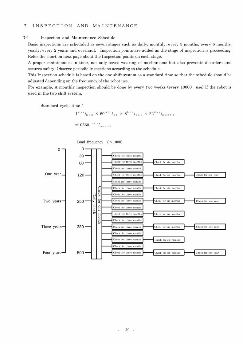
Basic inspections are scheduled as seven stages such as daily, monthly, every 3 months, every 6 months, yearly, every 2 years and overhaul. Inspection points are added as the stage of inspection is proceeding. Refer the chart on next page about the Inspection points on each stage. A proper maintenance in time, not only saves wearing of mechanisms but also prevents disorders and secures safety. Observe periodic Inspections according to the schedule. This Inspection schedule is based on the one shift system as a standard time so that the schedule should be adjusted depending on the frequency of the robot use. For example, A monthly inspection should be done by every two weeks (every 10000 use) if the robot is used in the two shift system.
Standard cycle time :
1use/min × 60min/hr × 8hrs/day × 22day/month
=10560 use/month
One year
Check for three months
0
Two years
Three years
Four years
0
30
60
120
250
380
500
Load frequency (×1000)
Check for three months
Check for three months
Check for three months
Check for three months
Check for three months
Check for three months
Check for three months
Check for three months
Check for three months
Check for three months
Check for three months
Check for three months
Check for three months
Check for three months
Check for three months
Check for six months
Check for six months
Check for six months
Check for six months
Check for six months
Check for six months
Check for six months
Check for six months
Check for one year
Check for one year
Check for one year
Check for one year
Daily check
Check for one m
onth
- - 21
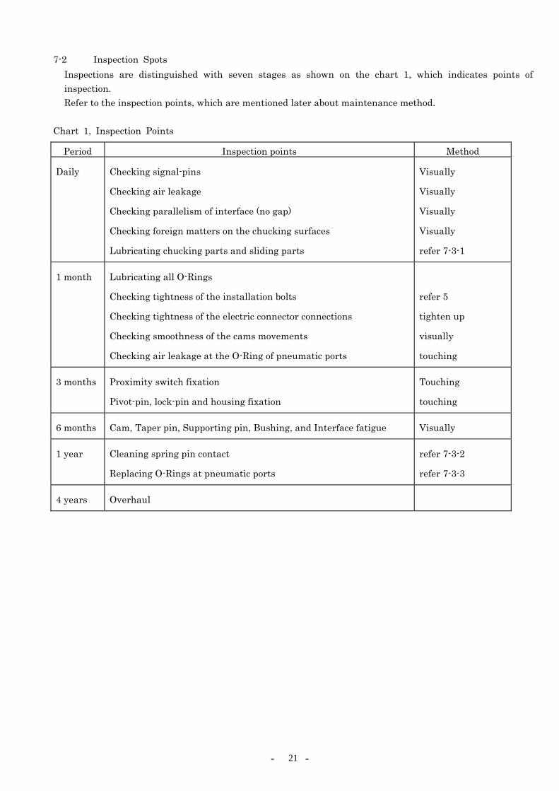
7-2 Inspection Spots Inspections are distinguished with seven stages as shown on the chart 1, which indicates points of inspection. Refer to the inspection points, which are mentioned later about maintenance method.
Chart 1, Inspection Points
Period Inspection points Method
Daily Checking signal-pins
Checking air leakage
Checking parallelism of interface (no gap)
Checking foreign matters on the chucking surfaces
Lubricating chucking parts and sliding parts
Visually
Visually
Visually
Visually
refer 7-3-1
1 month Lubricating all O-Rings
Checking tightness of the installation bolts
Checking tightness of the electric connector connections
Checking smoothness of the cams movements
Checking air leakage at the O-Ring of pneumatic ports
refer 5
tighten up
visually
touching
3 months Proximity switch fixation
Pivot-pin, lock-pin and housing fixation
Touching
touching
6 months Cam, Taper pin, Supporting pin, Bushing, and Interface fatigue Visually
1 year Cleaning spring pin contact
Replacing O-Rings at pneumatic ports
refer 7-3-2
refer 7-3-3
4 years Overhaul
- - 22
7-3 Maintenance outlines Daily maintenance without removing the Adaptors from the system is mentioned in this chapter.
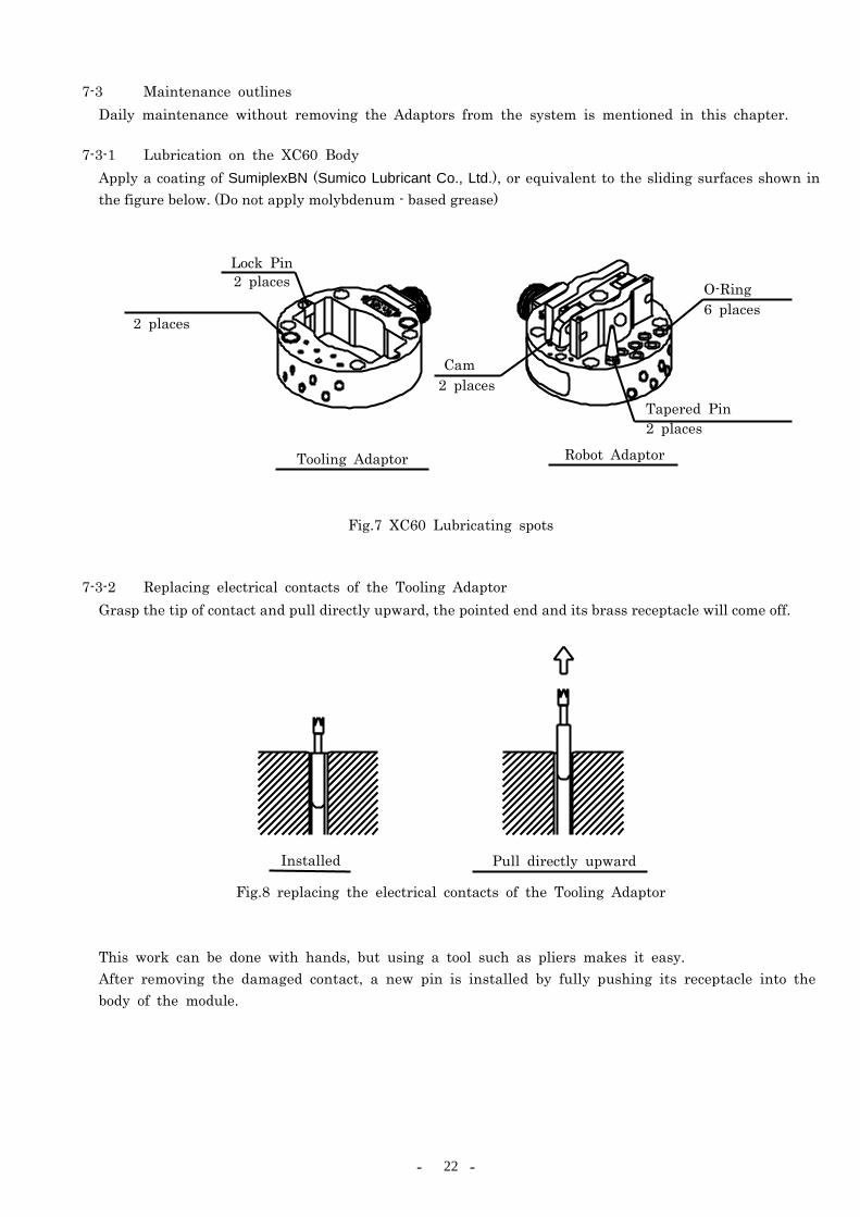
7-3-1 Lubrication on the XC60 Body Apply a coating of SumiplexBN (Sumico Lubricant Co., Ltd.), or equivalent to the sliding surfaces shown in the figure below. (Do not apply molybdenum - based grease)
Fig.7 XC60 Lubricating spots
7-3-2 Replacing electrical contacts of the Tooling Adaptor
Grasp the tip of contact and pull directly upward, the pointed end and its brass receptacle will come off.
Fig.8 replacing the electrical contacts of the Tooling Adaptor
This work can be done with hands, but using a tool such as pliers makes it easy. After removing the damaged contact, a new pin is installed by fully pushing its receptacle into the body of the module.
Lock Pin
O-Ring
Cam
Tapered Pin
Tooling Adaptor
2 places
2 places
2 places
6 places
2 places
Robot Adaptor
Installed Pull directly upward

- - 23
Check height and movement of the pins. If a pin is broken in the receptacle, use a pointed file(φ2~3mm, mid) to pull out the pin.
Fig. 9 removing a broken pin 7-3-3 Replacing O-Rings of the Air Port
The Robot Adaptor has O-Rings of the Air Port as shown on figure below. Replace a O-Ring if any damage or air leakage occurs. The old O-Rings may be removed by marking-off pin. In this time, be careful not to scratch the Robot Housing. The new O-Ring should be replaced in air port after a coating of grease application (SumiplexBN or equivalent). Check any damage on pneumatic ports, tapered pin, wear of bushings, and/or wrong teaching. These disorders may cause frequent damages of O-Rings. (refer 6-4)
Fig. 10 Replacing O-Rings of the Air Port
File
Spring
② Push and rotate ③ Pull upward ① Broken
Robot Adaptor
Marking-off Pin
O-Ring
- - 24
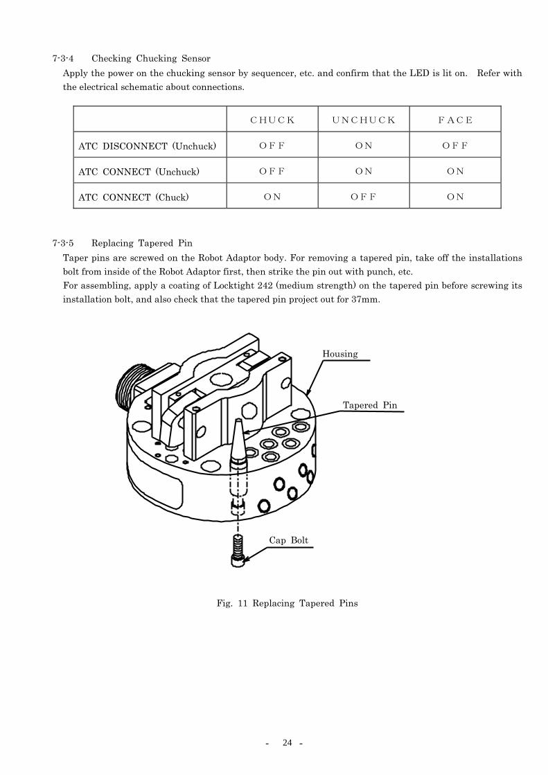
7-3-4 Checking Chucking Sensor Apply the power on the chucking sensor by sequencer, etc. and confirm that the LED is lit on. Refer with the electrical schematic about connections.
CHUCK UNCHUCK FACE
ATC DISCONNECT (Unchuck) OFF ON OFF
ATC CONNECT (Unchuck) OFF ON ON
ATC CONNECT (Chuck) ON OFF ON
7-3-5 Replacing Tapered Pin
Taper pins are screwed on the Robot Adaptor body. For removing a tapered pin, take off the installations bolt from inside of the Robot Adaptor first, then strike the pin out with punch, etc. For assembling, apply a coating of Locktight 242 (medium strength) on the tapered pin before screwing its installation bolt, and also check that the tapered pin project out for 37mm.
Fig. 11 Replacing Tapered Pins
Housing
Tapered Pin
Cap Bolt

- - 25
7-3-6 Replacing Locating Bushings Locating Bushings are pressed in the Tooling Adaptor body. For replacing, strike the Bushing out from A side.
Fig. 12 Replacing Bushing 7-3-7 Replacing Tooling Adaptor Lock-pins
Lock-pins are assembled as slide fit. For Replacing, untaught the setting screw and strike the pin out with the special jig. Apply small amount of Locktight 222 (Low strength) on the setting screw after inserting the pin. Then, tight the setting screw with adjusting the position of hole B.
Fig. 13 Replacing Lock-pins
Locating Bushing
Tooling Adaptor
A
Lock Pin
Setting screw
Tooling Adaptor
Special jig
B
- - 26
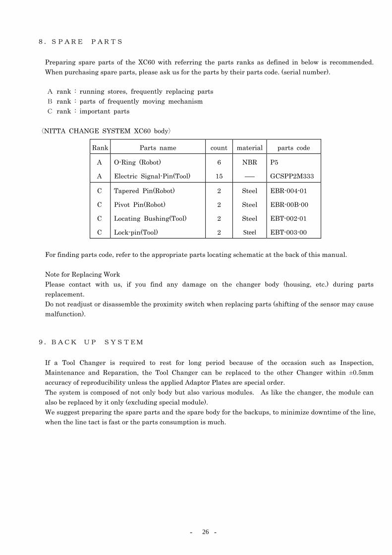
8.SPARE PARTS
Preparing spare parts of the XC60 with referring the parts ranks as defined in below is recommended. When purchasing spare parts, please ask us for the parts by their parts code. (serial number).
A rank : running stores, frequently replacing parts B rank : parts of frequently moving mechanism C rank : important parts
〈NITTA CHANGE SYSTEM XC60 body〉
Rank Parts name count material parts code
A
A
O-Ring (Robot)
Electric Signal-Pin(Tool)
6
15
NBR
――
P5
GCSPP2M333
C
C
C
C
Tapered Pin(Robot)
Pivot Pin(Robot)
Locating Bushing(Tool)
Lock-pin(Tool)
2
2
2
2
Steel
Steel
Steel
Steel
EBR-004-01
EBR-00B-00
EBT-002-01
EBT-003-00
For finding parts code, refer to the appropriate parts locating schematic at the back of this manual.
Note for Replacing Work Please contact with us, if you find any damage on the changer body (housing, etc.) during parts replacement. Do not readjust or disassemble the proximity switch when replacing parts (shifting of the sensor may cause malfunction).
9.BACK UP SYSTEM
If a Tool Changer is required to rest for long period because of the occasion such as Inspection, Maintenance and Reparation, the Tool Changer can be replaced to the other Changer within ±0.5mm accuracy of reproducibility unless the applied Adaptor Plates are special order. The system is composed of not only body but also various modules. As like the changer, the module can also be replaced by it only (excluding special module). We suggest preparing the spare parts and the spare body for the backups, to minimize downtime of the line, when the line tact is fast or the parts consumption is much.

- - 27
10.TROUBLE SHOOTING 10-1 Trouble Factors (Cause Chart)
The NITTA CHANGE SYSTEM does not work. ・Tools do not reposition for chucking.
・Gap is produced at the chucking surfaces.
・System is unable to chucked.
・System is unable to unchucked.
The NITTA CHANGE SYSTEM can not exchange signals. ・Chuck sensor does not work.
・Unchuck sensor does not work.
・Face sensor does not work.
The NITTA CHANGE SYSTEM has air leakage. ・Air leakage at input pneumatic port.
The NITTA CHANGE SYSTEM gets heat. ・The Adaptor body gets heat.
Tool (Guns, Hand, etc.) does not work. ・Lost of pneumatics.
・Unable to exchange CHANGE SYSTEM signals through electric signal-pins.
10-2 Trouble phenomena and shooting 10-2-1 The NITTA CHANGE SYSTEM does not work. Tools Do Not Reposition for Chucking
1) Check any gap between the Adaptors. ・・・・・Readjust the teaching. 2) Check any damage or extreme wears of
tapered pins. ・・・・・Replace the tapered pin.(Refer 7-3-5)
3) Check any damage or extreme wear of locating bushings.
・・・・・Replace the locating bushing(Refer 7-3-6)
4) Check looseness of installation bolts. ・・・・・Tighten up the bolt (Refer 5) 5) Check any overload on the body to change its
shape. ・・・・・Contact with our office.
6) Check any load over the rating. ・・・・・Contact with our office.
- - 28
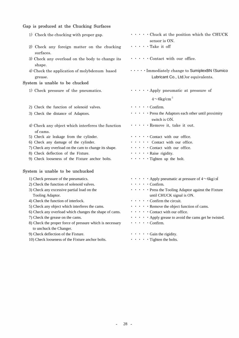
Gap is produced at the Chucking Surfaces
1) Check the chucking with proper gap.
・・・・・Chuck at the position which the CHUCK sensor is ON.
2) Check any foreign matter on the chucking surfaces.
・・・・・Take it off
3) Check any overload on the body to change its shape.
・・・・・Contact with our office.
4) Check the application of molybdenum based grease.
・・・・・Immediately change to SumiplexBN (Sumico Lubricant Co., Ltd.)or equivalents.
System is unable to be chucked
1) Check pressure of the pneumatics.
・・・・・Apply pneumatic at pressure of
4~6kg/cm2
2) Check the function of solenoid valves. ・・・・・Confirm. 3) Check the distance of Adaptors.
・・・・・Press the Adaptors each other until proximity switch is ON.
4) Check any object which interferes the function of cams.
・・・・・Remove it, take it out.
5) Check air leakage from the cylinder. ・・・・・Contact with our office. 6) Check any damage of the cylinder. ・・・・・ Contact with our office. 7) Check any overload on the cam to change its shape. ・・・・・Contact with our office. 8) Check deflection of the Fixture. ・・・・・Raise rigidity. 9) Check looseness of the Fixture anchor bolts. ・・・・・Tighten up the bolt.
System is unable to be unchucked
1) Check pressure of the pneumatics. ・・・・・Apply pneumatic at pressure of 4~6kg/ 2) Check the function of solenoid valves. ・・・・・Confirm. 3) Check any excessive partial load on the
Tooling Adaptor. ・・・・・Press the Tooling Adaptor against the Fixture
until CHUCK signal is ON.4) Check the function of interlock. ・・・・・Confirm the circuit. 5) Check any object which interferes the cams. ・・・・・Remove the object function of cams. 6) Check any overload which changes the shape of cams. ・・・・・Contact with our office. 7) Check the grease on the cams. ・・・・・Apply grease to avoid the cams get be twisted. 8) Check the proper force of pressure which is necessary
to unchuck the Changer. ・・・・・Confirm.
9) Check deflection of the Fixture. ・・・・・Gain the rigidity. 10) Check looseness of the Fixture anchor bolts. ・・・・・Tighten the bolts.
- - 29
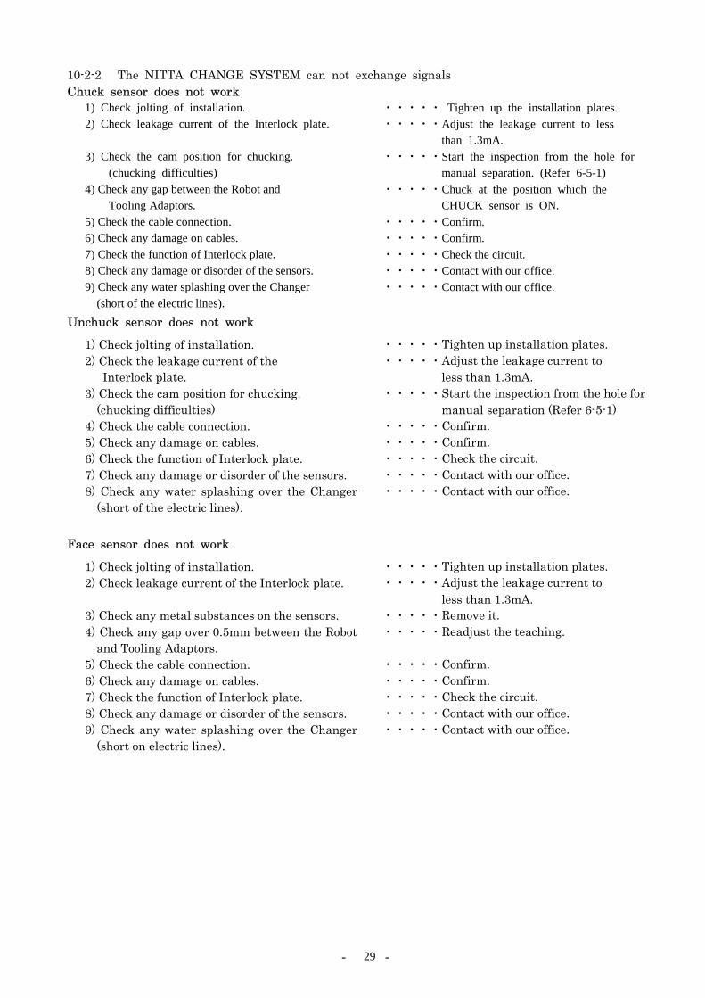
10-2-2 The NITTA CHANGE SYSTEM can not exchange signals Chuck sensor does not work
1) Check jolting of installation. ・・・・・ Tighten up the installation plates. 2) Check leakage current of the Interlock plate.
・・・・・Adjust the leakage current to less than 1.3mA.
3) Check the cam position for chucking. (chucking difficulties)
・・・・・Start the inspection from the hole for manual separation. (Refer 6-5-1)
4) Check any gap between the Robot and Tooling Adaptors.
・・・・・Chuck at the position which the CHUCK sensor is ON.
5) Check the cable connection. ・・・・・Confirm. 6) Check any damage on cables. ・・・・・Confirm. 7) Check the function of Interlock plate. ・・・・・Check the circuit. 8) Check any damage or disorder of the sensors. ・・・・・Contact with our office. 9) Check any water splashing over the Changer
(short of the electric lines). ・・・・・Contact with our office.
Unchuck sensor does not work
1) Check jolting of installation. ・・・・・Tighten up installation plates. 2) Check the leakage current of the
Interlock plate. ・・・・・Adjust the leakage current to
less than 1.3mA. 3) Check the cam position for chucking.
(chucking difficulties) ・・・・・Start the inspection from the hole for
manual separation (Refer 6-5-1) 4) Check the cable connection. ・・・・・Confirm. 5) Check any damage on cables. ・・・・・Confirm. 6) Check the function of Interlock plate. ・・・・・Check the circuit. 7) Check any damage or disorder of the sensors. ・・・・・Contact with our office. 8) Check any water splashing over the Changer
(short of the electric lines). ・・・・・Contact with our office.
Face sensor does not work
1) Check jolting of installation. ・・・・・Tighten up installation plates. 2) Check leakage current of the Interlock plate.
・・・・・Adjust the leakage current to less than 1.3mA.
3) Check any metal substances on the sensors. ・・・・・Remove it. 4) Check any gap over 0.5mm between the Robot
and Tooling Adaptors. ・・・・・Readjust the teaching.
5) Check the cable connection. ・・・・・Confirm. 6) Check any damage on cables. ・・・・・Confirm. 7) Check the function of Interlock plate. ・・・・・Check the circuit. 8) Check any damage or disorder of the sensors. ・・・・・Contact with our office. 9) Check any water splashing over the Changer
(short on electric lines). ・・・・・Contact with our office.

- - 30
10-2-3 The NITTA CHANGE SYSTEM has air leakage Air leakage at input pneumatic port
1) Check any damage on O-Ring of the Air Port on the Robot Adaptor.
・・・・・Replace O-Ring. (Refer 7-3-3)
2) Check connection of the one touch joint of pneumatic.
・・・・・Confirm.
3) Check the applications of hoses. ・・・・・Confirm. 4) Check any gap between the chucking surface
of the Robot and Tooling Adaptors. ・・・・・Chuck completely
10-2-4 The NITTA CHANGE SYSTEM gets heat The Adaptor body gets heat
1) Check the high temperature in atmosphere. ・・・・・Keep away from heat 2) Check the electric power on signal spring-pin. ・・・・・Keep power application within the rating.
10-2-5 Tool (Gun, Hand, etc.) does not work Lost of pneumatics
1) Check the pressure of pneumatic.
・・・・・Apply pneumatic at pressure less than 8.75kg/cm2
2) Check the function of solenoid valves Adaptors.
・・・・・Confirm.
3) Check the chucking of the Robot and Tooling Adaptors.
・・・・・Chuck completely (CHUCH sensor should be ON).
4) Check extreme bending or twisting on the hose.
・・・・・Confirm.
5) Check any damage on O-Rings of the Robot Adaptor.
・・・・・Replace O-Rings.
6) Check coincidence of port number between the Robot and Tooling Adaptor.
・・・・・Confirm.
7) Check any damage on the Tool. ・・・・・Confirm.
Unable to exchange signals through electric signal-pins
1) Check transmissions of signals to electric signal-pins.
・・・・・Check with tester, etc.
2) Check any damage on tools. ・・・・・Confirm. 3) Check extreme bending or twisting on the
signal cables. ・・・・・Confirm.
4) Check the connection of connectors. ・・・・・Connect completely. 5) Check the chucking of the Robot and Tooling
Adaptor. ・・・・・Chuck completely.
(CHUCK sensor should be ON) 6) Check any damage on the electric signal-pin
module. ・・・・・Contact with our office.
7) Check any foreign matter or damage on electric signal-pins of module.
・・・・・Replace electric signal-pin. (Refer 7-3-2)
8) Check any projection or dent of electric signal-pin(height of pins should be same).
・・・・・Contact with our office.
9) Check the movement of electric signal-pin (movement should be smooth).
・・・・・Replace electric signal-pins. (Refer 7-3-2)

- - 31
ATC “NITTA CHANGE SYSTEM” “XC60” USERS GUIDE
MAINTENANCE & INSTRUCTION MANUAL
Written Date 2010, October Edition 2 Edit・Issue Nitta Corporation
BUSINESS DEVELOPMENT CENTER MECHATRONICS SYSTEMS DEPT.
Contact Nitta Corporation BUSINESS DEVELOPMENT CENTER
Tokyo Branch 8-2-1, Ginza, Cyuo-ku, Tokyo, 104-0061 Japan
TEL +81-3-6744-2720 FAX +81-3-6744-2721
Nagoya Branch 1-17-23, Meieki-minami, Nakamura-ku, Nagoya, 450-0003 Japan
TEL +81-52-589-1310 FAX +81-52-586-5707
E-Mail:[email protected] URL:http://www.nitta.co.jp/product/mechasen/top.html
Please contact the nearest office for the content of this book.
When use in EU market, translate this book into official language at the place of installation.
This book occasionally changes the description matter without a previous notice for the improvement.
It is prohibited to reprint, and to reproduce this book without permission.


![The XC60 range at a glance. - MY VOLVO LIBRARY2].pdf · The XC60 range at a glance. 28 XC60 SE Rec Retail On the Road Basic £ VAT @ 17.5% £ Price £ Price ...](https://static.fdocuments.in/doc/165x107/60065874611d214d1974ddc0/the-xc60-range-at-a-glance-my-volvo-2pdf-the-xc60-range-at-a-glance-28-xc60.jpg)