
AT91SAM9RL64 Hands-On 01 Web 1 -...
34
AT91SAM9RL64 Hands-on 01: Getting Started with the AT91LIB Prerequisites • Hands-On - None • Knowledge Requirements - Basic understanding of microcontrollers - Basic knowledge of the C language - Basic knowledge of Integrated Development Tools • PC Platform - Windows ® 2000, Windows ® XP, Windows ® Vista • Software Requirements - IAR EWARM 5.20 - AT91SAM-ICE Drivers • Hardware - AT91SAM9RL-EK - AT91SAM-ICE (JTAG probe) - Null modem serial cable • Skill Level - Beginner • Estimated Completion Time - 90 minutes Introduction The purpose of this hands-on is to get confident with the IAR EWARM tool-chain and the AT91LIB. All exercises are based on our AT91SAM9RL Evaluation Kit. The following items will be reviewed: • IAR EWARM Compile Debug Add peripheral low level API to existing project • AT91SAM Software AT91LIB Getting Started project 32-bit AT91SAM Microcontrollers Training AT91-0001
Transcript of AT91SAM9RL64 Hands-On 01 Web 1 -...

AT91SAM9RL64 Hands-on 01: Getting Started with the AT91LIB
Prerequisites • Hands-On
- None • Knowledge Requirements
- Basic understanding of microcontrollers - Basic knowledge of the C language - Basic knowledge of Integrated Development Tools
• PC Platform - Windows ® 2000, Windows ® XP, Windows ® Vista
• Software Requirements - IAR EWARM 5.20 - AT91SAM-ICE Drivers
• Hardware - AT91SAM9RL-EK - AT91SAM-ICE (JTAG probe) - Null modem serial cable
• Skill Level - Beginner
• Estimated Completion Time - 90 minutes
Introduction The purpose of this hands-on is to get confident with the IAR EWARM tool-chain and the AT91LIB. All exercises are based on our AT91SAM9RL Evaluation Kit.
The following items will be reviewed:
• IAR EWARM
� Compile
� Debug
� Add peripheral low level API to existing project
• AT91SAM Software
� AT91LIB
� Getting Started project
32-bit AT91SAM
Microcontrollers
Training AT91-0001

2 AT91 Hands-On
Training AT91-0001
Document Overview The hands-on is split into several different assignments. Each assignment is further divided into individual sections to simplify understanding.
Throughout this document you will find some special icons. These icons are used to identify different sections of assignments and ease complexity.
Information Delivers contextual information about a specific topic
Tip Highlights useful tips and techniques
To do Highlights objectives to be completed in italicized text
Result Highlights the expected result of an assignment step
Warning Indicates important information
Abbreviations • AT91LIB: AT91SAM Software Library

AT91 Hands-On 01
3
Training AT91-0001
Table of Contents Prerequisites ....................................................................................... 1
Introduction......................................................................................... 1
Document Overview ........................................................................... 2
Abbreviations...................................................................................... 2
Table of Contents................................................................................ 3
1 Hardware Requirement.................................................................... 5
1.1 Evaluation Kit....................................................................................................... 5
1.2 Emulator .............................................................................................................. 5
2 Software Requirement..................................................................... 6
2.1 Development tools............................................................................................... 6
3 Hands-On Setup............................................................................... 7
3.1 Objectives............................................................................................................ 7
3.2 AT91SAM Software Package.............................................................................. 7
3.3 AT91LIB............................................................................................................... 8
3.4 Setup ................................................................................................................. 10 3.4.1 Evaluation Kit Installation ........................................................................................ 10 3.4.2 SAM-ICE Installation ............................................................................................... 11 3.4.3 RS232 & HyperTerminal.......................................................................................... 13
4 Hands-On - Assignment 1 ............................................................. 15
4.1 Objectives.......................................................................................................... 15
4.2 IAR EWARM...................................................................................................... 15
4.3 Exercises ........................................................................................................... 15 4.3.1 A1 – Step 0.............................................................................................................. 15 4.3.2 A1 – Step 1.............................................................................................................. 18
4.4 Summary ........................................................................................................... 22
5 Hands-On - Assignment 2 ............................................................. 23
5.1 Objectives.......................................................................................................... 23
5.2 AT91SAM Pulse Width Modulation ................................................................... 23
5.3 AT91 PWM Peripheral Low Level API .............................................................. 24
5.4 Exercises ........................................................................................................... 24 5.4.1 A2 – Step 0.............................................................................................................. 24 5.4.2 A2 – Step 1.............................................................................................................. 26 5.4.3 A2 – Step 2.............................................................................................................. 28 5.4.4 A2 – Step 3 – Optional ............................................................................................ 28
5.5 Summary ........................................................................................................... 29
6 Hands-On - Assignment 3 ............................................................. 30
6.1 Objectives.......................................................................................................... 30
6.2 AT91SAM RTC.................................................................................................. 30
6.3 AT91 RTC Peripheral Low Level API ................................................................ 31
4 AT91 Hands-On
Training AT91-0001
6.4 Exercises ........................................................................................................... 31 6.4.1 A3 – Step 0.............................................................................................................. 31 6.4.2 A3 – Step 1.............................................................................................................. 31 6.4.3 A3 – Step 2 – Optional ............................................................................................ 32
6.5 Summary ........................................................................................................... 32
7 Hands-On Summary ...................................................................... 33
8 Resources....................................................................................... 34
9 Atmel Technical Support Resources ........................................... 34

AT91 Hands-On 01
5
Training AT91-0001
1 Hardware Requirement
1.1 Evaluation Kit
• AT91SAM9RL-EK
The AT91SAM9RL-EK is the AT91SAM9RL product series evaluation kit.
1.2 Emulator
• SAM-ICE JTAG Probe
SAM-ICE is a JTAG emulator designed for all ATMEL AT91SAM ARM7/ARM9 cores. USB driver files to support the SAM-ICE are part of the SAM-ICE Software.

6 AT91 Hands-On
Training AT91-0001
2 Software Requirement
2.1 Development tools
IAR EWARM 5.20
As stated in the Prerequisites section, the install ation of the IAR tool-chain must be done prior to the beginning of this hands-o n session. The license is free for the IAR EWARM 5.20 KickStart edition.
The IAR EWARM 5.20 KickStart edition can be downloaded from the http://www.iar.com/ website using the following link:
http://supp.iar.com/Download/SW/?item=EWARM-KS32
SAM-ICE Software SAM-ICE (J-Link) software includes:
• USB driver
• J-Mem
• jlink.exe and jlinkarm.dll
• J-Flash*
• J-Link RDI (includes flash downloader* and support unlimited number of flash breakpoints*)
• GDB server * (license required) The SAM-ICE software can be downloaded from the http://www.segger.com website using the following link:
http://www.segger.com/download_jlink.html

AT91 Hands-On 01
7
Training AT91-0001
3 Hands-On Setup
3.1 Objectives
• Understand the AT91 Software Package & AT91LIB
• Setting-up the AT91SAM9RL-EK board
• Installing the SAM-ICE dll
• Serial Debug Interface setting
3.2 AT91SAM Software Package
The AT91SAM Software Package consists of AT91 microcontroller drivers, software services & libraries, and demonstration applications. Each software module is provided with full source code, example of usage, rich html documentation and ready-to-use projects for the GNU GCC and IAR EWARM compilers.
Each AT91SAM device has its own AT91SAM Software package.
Each AT91SAM Software Package contains the following:
AT91SAM Software Package location You can find all AT91SAM Software packages under the following link:
http://www.atmel.com/dyn/products/tools_card.asp?tool_id=4343
AT91LIB Basic Software examples and Demos USB Framework
Getting Started
AT91SAM Information
Toolkit (IAR, GNU)
8 AT91 Hands-On
Training AT91-0001
AT91SAM Update for IAR EWARM Automatic EWARM update can be done thanks to an executable file located at the same place as the AT91SAM Software Package within www.atmel.com. This automatic update adds support for all AT91SAM devices to IAR EWARM when a new Software Package is released. It contains:
- All software package examples
- Latest flashers
- An updated board description file detects, backs up and automatically updates the Atmel/AT91 related directories in EWARM program files.
The AT91LIB and all Basic Software examples of the Software Package version 1.4 are already integrated within the EWARM 5.20.
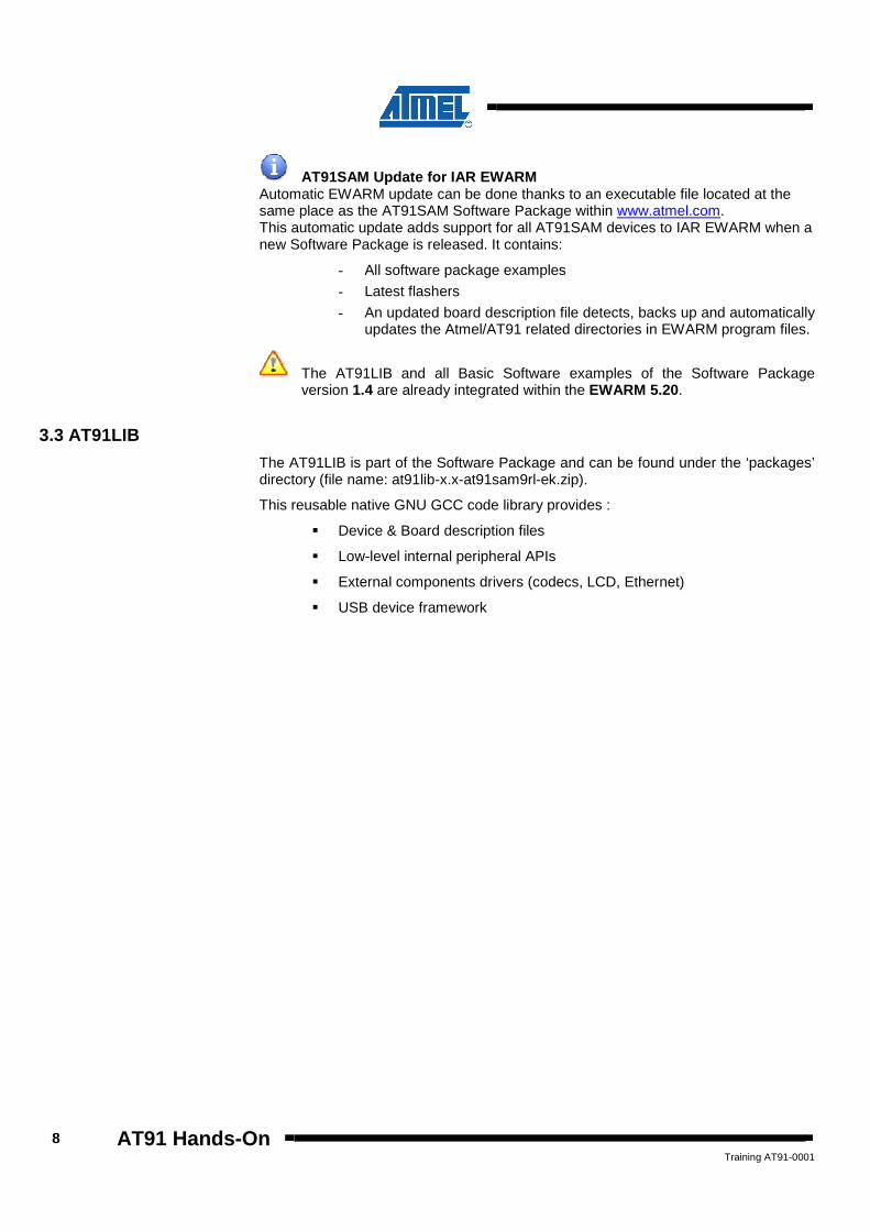
3.3 AT91LIB
The AT91LIB is part of the Software Package and can be found under the ‘packages’ directory (file name: at91lib-x.x-at91sam9rl-ek.zip).
This reusable native GNU GCC code library provides :
� Device & Board description files
� Low-level internal peripheral APIs
� External components drivers (codecs, LCD, Ethernet)
� USB device framework

AT91 Hands-On 01
9
Training AT91-0001
AT91LIB Architecture
AT91LIB Only ”boards” directory is AT91SAM device dependant.
C-Startup, low level initialization Device register description file
On-board external devices : CODECs DACs Keyboard matrix Segment LCD Sensors
Etc…
Nandflash, Norflash, Etc ISP Applets
API for each peripheral Low level functions
USB Framework
Standard library functions stdio, string, …
General-purpose functions LEDs, debug trace, etc …

10 AT91 Hands-On
Training AT91-0001
3.4 Setup
3.4.1 Evaluation Kit Installation
3.4.1.1 Introduction
The AT91SAM9RL-EK is powered using a wall plugged power supply.
The power supply voltage is +5V.
3.4.1.2 Board Install
Here is the default jumpers’ configuration on the AT91SAM9RL-EK kit:
Check now the following Jumpers connection:
J3 Closed
J11 Position 1-2 (3v3-BMS)
J12 Open
J13 Open
All other Jumpers must be closed
Power the board: • Connect wall plugged power supply to the board
J12 & J13
J11
LED - DS1/2/3 BP1 & BP2
Open

AT91 Hands-On 01
11
Training AT91-0001
The AT91SAM9RL-EK is well configured. 3.4.2 SAM-ICE Installation
Update SAM-ICE software: • Install the last SAM-ICE software: Setup_JLinkARM_Vxxxx.exe
• A Segger dll update is needed for all tool-chains using it. At the following prompt click on ‘Select all’ and click ‘OK’:
The SAM-ICE software and the J-LINK dll update are done. Connect the SAM-ICE:
• Connect the SAM-ICE to the AT91SAM9RL-EK ensuring the proper orientation of the JTAG connector
• Connect the SAM-ICE to the PC (USB port)
The SAM-ICE will install automatically. • A new hardware is found:
• The “Found New Hardware” wizard pops up:
JTAG Interface
Power Supply
DBGU

12 AT91 Hands-On
Training AT91-0001
Update SAM-ICE firmware and check SAM-ICE connection: • Launch J-Link Commander application through the desktop “start” menu:
“All Program” → “SEGGER” → “J-Link ARM Vx.xx” → “J-Link Commander”
• A Command Prompt window pops up:
The SAM-ICE firmware is well updated and the SAM-ICE is well connected to the AT91SAM9RL-EK.

AT91 Hands-On 01
13
Training AT91-0001
3.4.3 RS232 & HyperTerminal
Connect the RS232 cable to one RS232 computer Port. • Connect the RS232 cable to the DBGU connector
• Launch HyperTerminal application through the desktop “start” menu: “All Program” → “Accessories” → “Communication” → “HyperTerminal”
• Set a connection name, for example we select AT91SAM:
• Select the correct COM port number (usually COM1):
14 AT91 Hands-On
Training AT91-0001
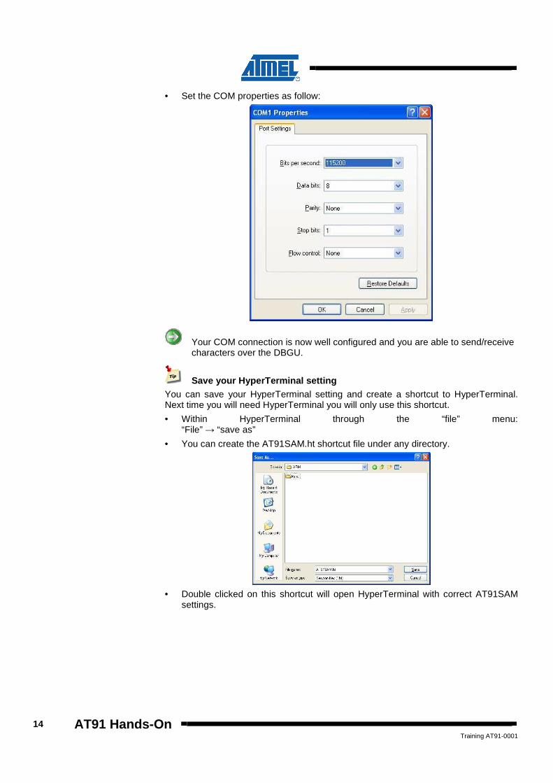
• Set the COM properties as follow:
Your COM connection is now well configured and you are able to send/receive characters over the DBGU.
Save your HyperTerminal setting You can save your HyperTerminal setting and create a shortcut to HyperTerminal. Next time you will need HyperTerminal you will only use this shortcut.
• Within HyperTerminal through the “file” menu: “File” → “save as”
• You can create the AT91SAM.ht shortcut file under any directory.
• Double clicked on this shortcut will open HyperTerminal with correct AT91SAM
settings.
AT91 Hands-On 01
15
Training AT91-0001
4 Hands-On - Assignment 1
4.1 Objectives
The goal of this assignment is to build, debug and get confident with the IAR EWARM tool-chain environment an existing example.
In this Assignment you will:
• Using IAR
� Launch IAR EWARM
� Open the AT91SAM9RL-EK Getting Started Project integrated in IAR
� Compile & Debug the AT91SAM9RL-EK Getting Started
� Use several IAR features
4.2 IAR EWARM
IAR EWARM (Embedded Workbench for ARM) is an integrated development environment for building and debugging embedded applications. It provides extensive support for a wide range of ARM devices, hardware debug systems and RTOSs and generates very compact and efficient code. Ready-made device configuration files, flash loaders and over example projects are included.
All IAR EWARM screenshots provided in this document are based on the IAR EWARM V5.20 version.
4.3 Exercises
4.3.1 A1 – Step 0
You will now start the IAR EWARM and open an embedded project.
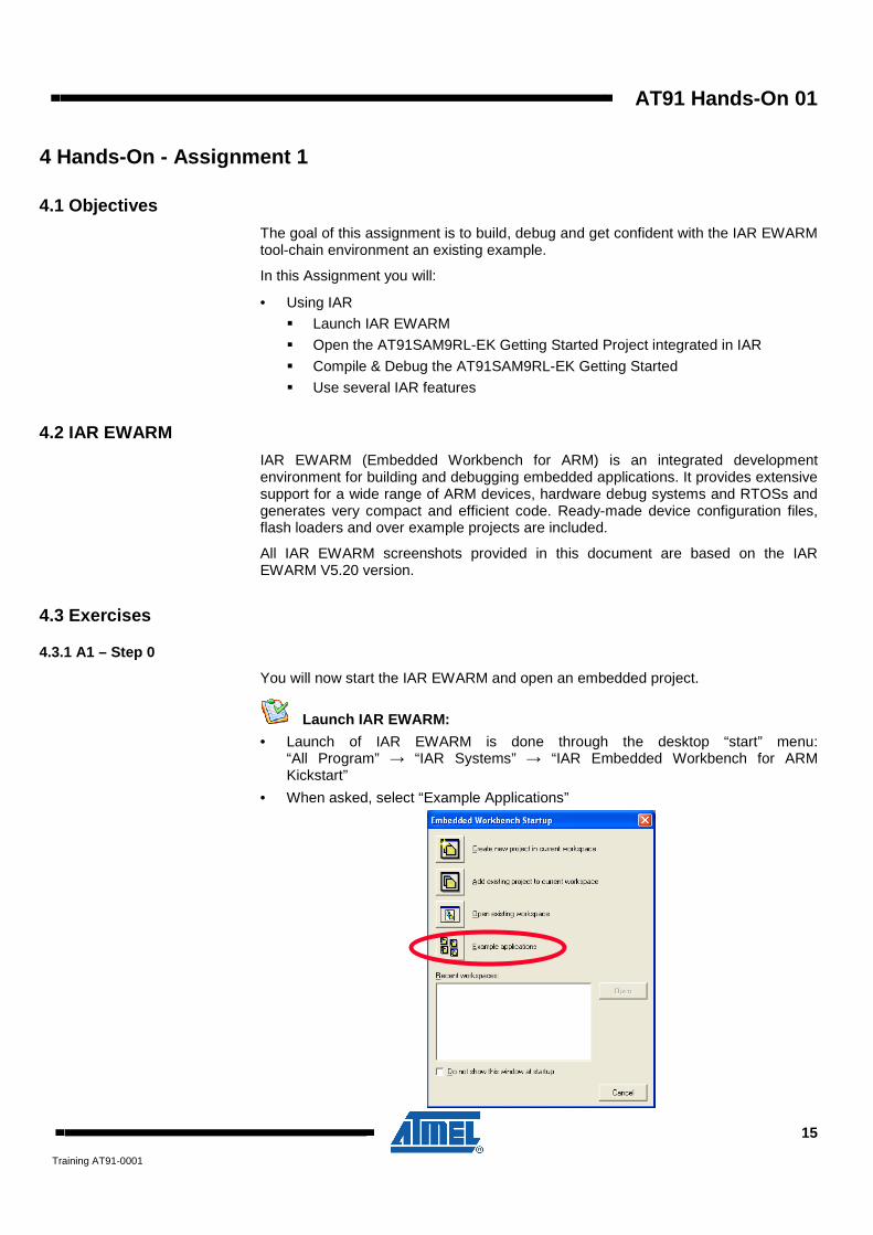
Launch IAR EWARM: • Launch of IAR EWARM is done through the desktop “start” menu:
“All Program” → “IAR Systems” → “IAR Embedded Workbench for ARM Kickstart”
• When asked, select “Example Applications”

16 AT91 Hands-On
Training AT91-0001
• Select “ATMEL” → “at91sam9rl-ek” → “getting-started-project” then click on OPEN.
Embedded Workbench Startup Screen You can access anytime to the Startup Screen using the “Help” menu:
IAR Project Examples IAR EWARM integrates all Software Package projects examples. You can find all projects examples using the Startup screen.
Software Package version 1.4 is already integrated within the EWARM 5.20 (AT91LIB and all Basic Software examples).

AT91 Hands-On 01
17
Training AT91-0001
• Select the path to store the Getting Started project. In the following example, the workspace is stored under the location: C:\AT91\
IAR will automatically create the following directory tree:
By selecting C:\AT91\ as install directory, IAR will create the ARM and Atmel directory. The Atmel directory contains:
- Exhaustive AT91LIB
- Project repository directory by Evaluation Kit (ex: at91sam9rl-ek)
- Documentation which describe each project
- Resources which contain all macro files used by EWARM to initialize the different targets
• You get the following screen:
AT91SAM9RL-EK Getting Started Project is now well configured.

18 AT91 Hands-On
Training AT91-0001
4.3.2 A1 – Step 1
You will now Compile and Debug the Getting Started project.
IAR EWARM Workspace The Workspace window displays a hierarchical view of the source files, dependency files, output files and how they are logically grouped. Hereafter is the example for the AT91SAM9RL-EK Getting Started Project:
For this example, you can select the project with a different build configuration, choose that build configuration from the drop-down list at the top of the Workspace window. Hereafter is the example for the AT91SAM9RL-EK Getting Started Project:
Macro File A setup macro file is a standard macro file that you choose to load automatically before your application is launched. You can define the setup macro file to perform actions according to your needs, by using setup macro functions and system macros. Thus, by loading a setup macro file you can initialize internal clocks or any peripherals of your AT91SAM device before your application starts. The Getting Started macro files are under ‘resources’ directory (see workspace above).
Linker File Program code and data are placed in memory according to the configuration specified in the linker configuration file. It is important to be familiar with its syntax to understand how sections are placed in memory. The Getting Started linker files (sdram.icf & sram.icf) can be found under: C:\AT91\ARM\Atmel\at91lib\boards\at91sam9rl-ek\at91sam9rl64
How to learn more? You can access anytime to the EWARM User Guide using the “Help” menu: ARM Embedded Workbench User guide (pdf file)
AT91 Hands-On 01
19
Training AT91-0001
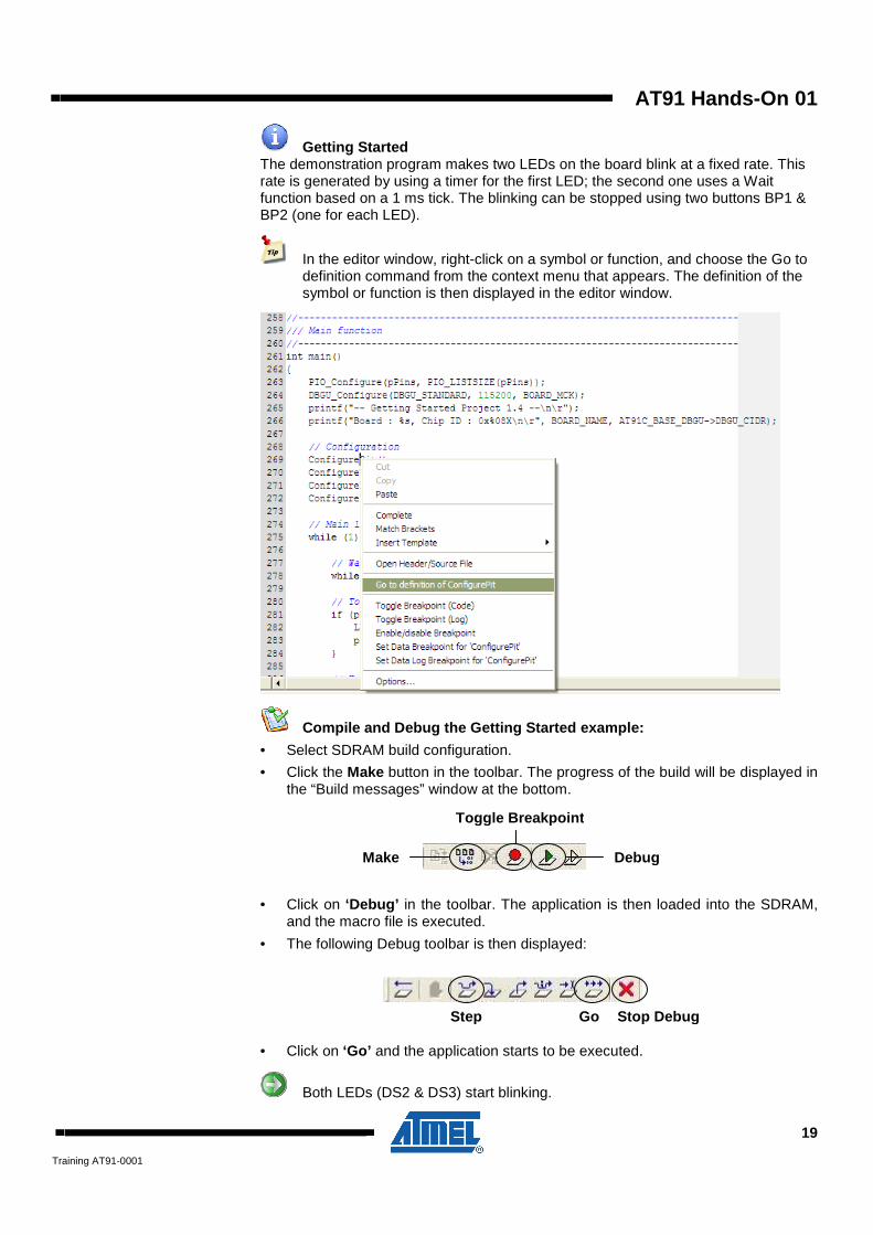
Getting Started The demonstration program makes two LEDs on the board blink at a fixed rate. This rate is generated by using a timer for the first LED; the second one uses a Wait function based on a 1 ms tick. The blinking can be stopped using two buttons BP1 & BP2 (one for each LED).
In the editor window, right-click on a symbol or function, and choose the Go to definition command from the context menu that appears. The definition of the symbol or function is then displayed in the editor window.
Compile and Debug the Getting Started example:
• Select SDRAM build configuration.
• Click the Make button in the toolbar. The progress of the build will be displayed in the “Build messages” window at the bottom.
• Click on ‘Debug’ in the toolbar. The application is then loaded into the SDRAM, and the macro file is executed.
• The following Debug toolbar is then displayed:
• Click on ‘Go’ and the application starts to be executed.
Both LEDs (DS2 & DS3) start blinking.
Go Step
Debug Make
Toggle Breakpoint
Stop Debug

20 AT91 Hands-On
Training AT91-0001
The Getting Started outputs can be seen over HyperTerminal:
• Then to stop the execution of the application you can click on ‘Stop’ .
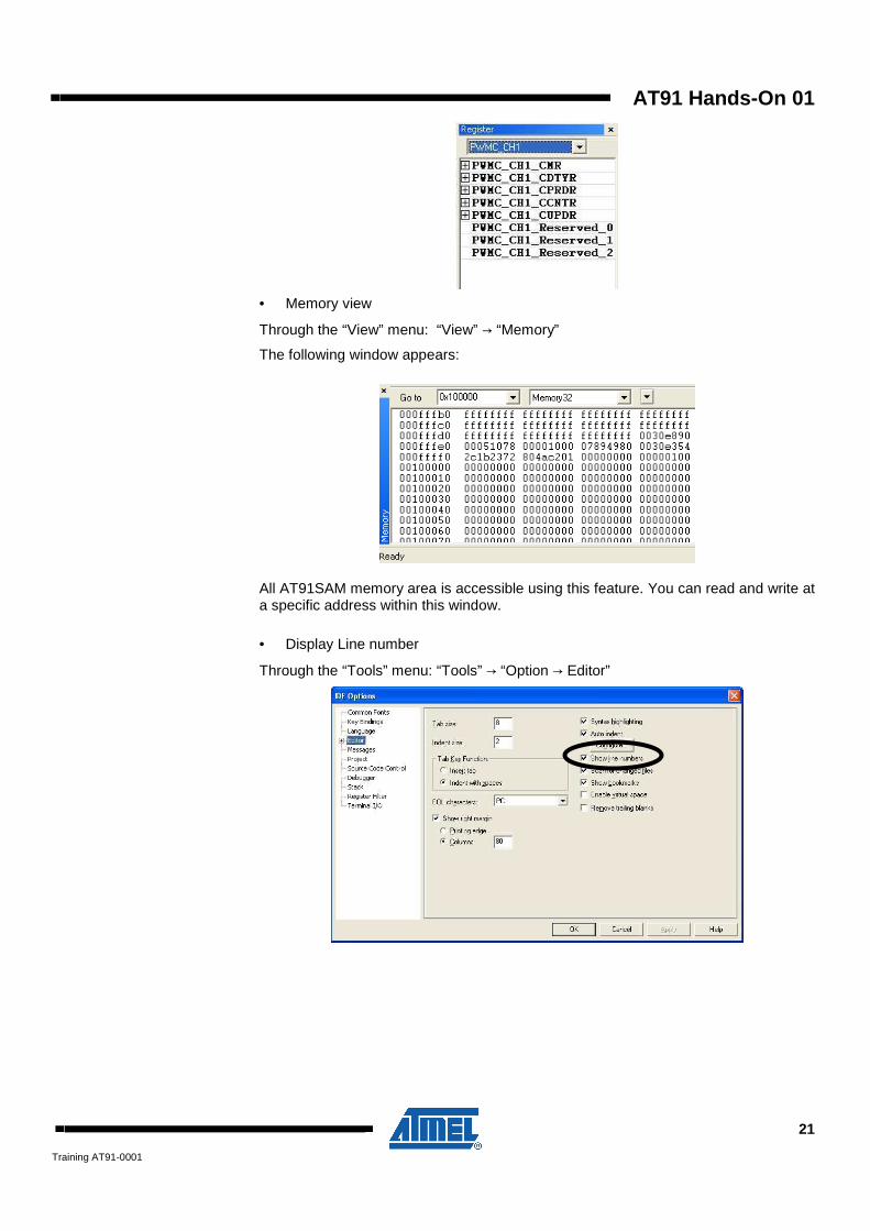
Use several features: • Register view
Through the “View” menu:
“View” → “Register”
The following window appears:
All AT91SAM registers are also accessible using the scrolling menu.
For example you can get access to the PWM Channel1 registers as follow; of course this access is only possible when the core is stopped.
Stop
AT91 Hands-On 01
21
Training AT91-0001
• Memory view
Through the “View” menu: “View” → “Memory”
The following window appears:
All AT91SAM memory area is accessible using this feature. You can read and write at a specific address within this window.
• Display Line number
Through the “Tools” menu: “Tools” → “Option → Editor”

22 AT91 Hands-On
Training AT91-0001
• Set a breakpoint
1- Stop the execution of the application 2- Put the cursor to line 205 3- Click on Toggle Breakpoint. 4- Click on Go
The LED DS2 is switched ON and OFF every time the application is going through the Timer Counter service routine.
Do not forget to remove the Breakpoint and to stop the debug before next step.
4.4 Summary
The above exercise illustrates how to:
• Open an AT91SAM IAR EWARM integrated Project • Compile and Debug a Project • Use several features for debug

AT91 Hands-On 01
23
Training AT91-0001
5 Hands-On - Assignment 2
5.1 Objectives
The goal of this assignment is to add a peripheral to the existing Getting Started project.
In this Assignment you will:
• Add PWM peripheral to the Getting Started Project
• Set-up PWM output to control LED brightness
• Compile & Debug the application with the IAR tool-chain
5.2 AT91SAM Pulse Width Modulation
The Pulse Width Modulation (PWM) module contains four independent PWM channels. Each channel has a 16-bit counter and controls one square output waveform. Characteristics of the output waveform such as period, duty-cycle, and polarity are configurable.
Channels can be synchronized to generate non overlapped waveforms. All channels integrate a double buffering to prevent glitches on the output waveform when modifying the period or the duty-cycle.
Each of the four PWM Channels contains:
� One 16-bit counter
� Independent enable/disable
� Independent clock selection
� Independent period and duty cycle
� Double buffering of period and duty cycle
� Programmable output waveform polarity
� Programmable center or left aligned output waveform
The following figure illustrates the block diagram for one PWM channel.
Each PWM channel is composed of three blocks:
• A clock selector which selects one of the clocks provided by the clock generator: Clocks A or Clock B or prescaled MCK. Clocks A and Clock B are generated from the Master Clock (MCK).
• An internal counter clocked by the output of the clock selector. This internal counter is incremented or decremented according to the channel configuration and comparators events. The size of the internal counter is 16 bits.

24 AT91 Hands-On
Training AT91-0001
• A comparator used to generate events according to the internal counter value. It also computes the PWMx output waveform according to the configuration.
5.3 AT91 PWM Peripheral Low Level API
The PWM peripheral low level API is split between two files that define a useful set of functions for the PWM controller:
pwmc.c pwmc.h
Below is a list of some functions in the AT91LIB used during this hands-on:
• PWMC_ConfigureChannel(channel,prescaler,alignment, polarity)
Initialize the PWM controller.
• PWMC_ConfigureClocks (Clock A, Clock B, Reference Clock)
Configure PWM clocks A & B to run at the given frequencies.
• PWMC_SetPeriod(channel, period)
Set the period value used by a PWM channel using update register
• PWMC_SetDutyCycle(channel, duty)
Set the duty cycle used by a PWM channel using update register
• PWMC_EnableChannel(channel)
Starts PWM channels
5.4 Exercises
5.4.1 A2 – Step 0
Before starting this assignment, you need to modify the workspace and add the PWM peripheral low level API to the Hands-on Getting Started project.
Update the project with a new main.c file As the assignment ‘TODO’ information is not present within the default main.c file, you need to use a modified main.c file.
• Replace the modified main.c (find it within the Hands-On\01\setup directory provided to you) into the getting started directory:
Copy the main.c file to the C:\AT91\ARM\Atmel\at91sam9rl-ek\getting-started-project folder. It will be automatically refreshed under IAR.
The main.c has been replaced and contains the TODO information.

AT91 Hands-On 01
25
Training AT91-0001
Add the PWM peripheral low level API: Add the PWM peripheral low level API using “Add Group…” and “Add Files…” by right clicking on the peripherals directory.
• Add the pwmc group to the peripherals directory in the at91lib folder (Add Group…)
• Select pwmc name
• Then select pwmc.c and pwmc.h files within the at91lib directory located in the
project (Add Files…):
26 AT91 Hands-On
Training AT91-0001
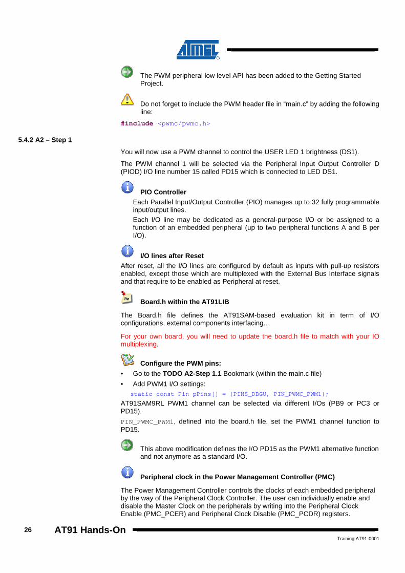
The PWM peripheral low level API has been added to the Getting Started Project.
Do not forget to include the PWM header file in “main.c” by adding the following line:
#include <pwmc/pwmc.h>
5.4.2 A2 – Step 1
You will now use a PWM channel to control the USER LED 1 brightness (DS1).
The PWM channel 1 will be selected via the Peripheral Input Output Controller D (PIOD) I/O line number 15 called PD15 which is connected to LED DS1.
PIO Controller Each Parallel Input/Output Controller (PIO) manages up to 32 fully programmable input/output lines.
Each I/O line may be dedicated as a general-purpose I/O or be assigned to a function of an embedded peripheral (up to two peripheral functions A and B per I/O).
I/O lines after Reset After reset, all the I/O lines are configured by default as inputs with pull-up resistors enabled, except those which are multiplexed with the External Bus Interface signals and that require to be enabled as Peripheral at reset.
Board.h within the AT91LIB The Board.h file defines the AT91SAM-based evaluation kit in term of I/O configurations, external components interfacing…
For your own board, you will need to update the board.h file to match with your IO multiplexing.
Configure the PWM pins: • Go to the TODO A2-Step 1.1 Bookmark (within the main.c file)
• Add PWM1 I/O settings: static const Pin pPins[] = {PINS_DBGU, PIN_PWMC_PWM1};
AT91SAM9RL PWM1 channel can be selected via different I/Os (PB9 or PC3 or PD15).
PIN_PWMC_PWM1, defined into the board.h file, set the PWM1 channel function to PD15.
This above modification defines the I/O PD15 as the PWM1 alternative function and not anymore as a standard I/O.
Peripheral clock in the Power Management Controller (PMC) The Power Management Controller controls the clocks of each embedded peripheral by the way of the Peripheral Clock Controller. The user can individually enable and disable the Master Clock on the peripherals by writing into the Peripheral Clock Enable (PMC_PCER) and Peripheral Clock Disable (PMC_PCDR) registers.

AT91 Hands-On 01
27
Training AT91-0001
Enable the PWM clock: • Go to the TODO A2-Step 1.2 bookmark and add the following line
AT91C_BASE_PMC->PMC_PCER = 1 << AT91C_ID_PWMC;
PWM – Center Aligned The Period and the Duty cycle can be configured using two registers: PWM_CPRDx (period register) and PWM_CDTYx (duty cycle register), where x is the channel number.
If PWM_CPRDx or PWM_CDTYx registers have been already written once, the period or the duty cycle update have to be done thanks to dedicated update registers called PWM_ CUPDx registers (double buffering feature).
PWM_CPRDx and PWM_CDTYx registers give the limit of internal counters allowing the waveform generation. See below a PWM output waveform example using center aligned waveform (CALG = 1) which starts at a low level (polarity CPOL = 0):
Configure the PWM channel: • Go to the TODO A2-Step 1.3 bookmark and add the following lines
• Set clock A to run at 30000Hz from MCK (clock B is not used) PWMC_ConfigureClocks(30000, 0, BOARD_MCK);
• Configure PWMC: Channel #1, Clk A, Left aligned, start at a low level PWMC_ConfigureChannel(1, AT91C_PWMC_CPRE_MCKA, 0, 0);
• Set the PWM Period to 0.67 ms (CPRD)
T=2 x CPRD / 30000 => CPRD=10 PWMC_SetPeriod(1, 10);
• Set the Duty cycle to 10% (CDTY)
The CPRD is 10, so to get 10% the duty cycle value is 1. PWMC_SetDutyCycle(1, 1);
Period
Duty

28 AT91 Hands-On
Training AT91-0001
Enable the PWM channel:
• Go to the TODO A2-Step 1.4 bookmark and add the following lines
• Enable the PWM Channel 1 PWMC_EnableChannel(1);
• Compile and debug this step
The LED1 output is dim due to the duty cycle of 10%. 5.4.3 A2 – Step 2
You will now modify the PWM duty cycle to control the LED1 brightness. This can be accomplished by incrementing the CUPD field using the PWMC_SetDutyCycle() function as this function check if the CDTY (duty cycle) has already been written.
Update the PWM duty cycle: • Go to the TODO A2-Step 2.1 bookmark and add the following line
• Set the duty cycle to 100%
The period is 10. So to get 100% of duty cycle, value to enter is 10. PWMC_SetDutyCycle(1, 10);
It is possible to directly re-compile and reload th e updated application without quitting the debug window by clicking on th e following button
once the modifications on the code made:
The LED1 brightness increases thanks to the PWM duty cycle modification. 5.4.4 A2 – Step 3 – Optional
This step is optional: come back to this step when you have completed all Hands-on Assignments.
You will now modify the PWM duty cycle to control the LED1 brightness. The LED1 brightness needs to slowly increase in 10 different steps. This can be accomplished by incrementing the CUPD field. This update is done using the PWMC_SetDutyCycle() function and the DutyCycle variable.
Update the PWM duty cycle: • Within the while(1) loop, set the duty cycle from 0 to 100% using 10 steps to
slowly increases the LED1 brightness.
• Go to the TODO A2-Step 3.1 Optional bookmark and add necessary lines
The LED1 brightness slowly increases in steps thanks to the PWM duty cycle modification.

AT91 Hands-On 01
29
Training AT91-0001
5.5 Summary
The above exercise illustrates how to:
• Open an existing IAR project
• Add an AT91LIB peripheral low level API to an IAR project
• Assign an alternate function to a PIO port pin
• Setup a PWM channel in fixed period mode and variable duty cycle mode
• Update the PWM duty cycle

30 AT91 Hands-On
Training AT91-0001
6 Hands-On - Assignment 3
6.1 Objectives
The goal of this assignment is to add a new peripheral to the existing Getting Started project.
In this Assignment you will:
• Add RTC peripheral to the Getting Started Project
• Set and display over the DBGU the time
• Use the RTC as Time base
• Compile & Debug the application with the IAR tool-chain
6.2 AT91SAM RTC
The Real-time Clock (RTC) peripheral is designed for very low power consumption.
It combines a complete time-of-day clock with alarm and a two-hundred-year Gregorian calendar, complemented by a programmable periodic interrupt. The alarm and calendar registers are accessed by a 32-bit data bus.
The time and calendar values are coded in binary-coded decimal (BCD) format. The time format can be 24-hour mode or 12-hour mode with an AM/PM indicator.
Updating time and calendar fields and configuring the alarm fields are performed by a parallel capture on the 32-bit data bus. An entry control is performed to avoid loading registers with incompatible BCD format data or with an incompatible date according to the current month/year/century.

AT91 Hands-On 01
31
Training AT91-0001
6.3 AT91 RTC Peripheral Low Level API
The RTC peripheral low level API is split between two files that define a useful set of functions for the RTC controller:
rtc.c rtc.h
Below is a list of some functions in the AT91LIB used during this hands-on:
• RTC_SetTime (hour, minute, second)
Set the current time in the RTC registers
• RTC_GetTime(Hour, Minute, Second)
Retrieve the current time as stored in the RTC registers in several variables
6.4 Exercises
6.4.1 A3 – Step 0
Before starting this assignment, you need to add the RTC peripheral low level API to the Getting Started project.
Add the RTC peripheral low level API: Add the RTC peripheral low level API using “Add Group…” and “Add Files…” by right clicking on the peripheral directory.
• Add the rtc group to the peripheral directory
• Select rtc name
• Then select rtc.c and rtc.h files within the at91lib directory
The RTC peripheral low level API has been added to the Getting Started Project.
Do not forget to include the RTC header file in “main.c” by adding the following line:
#include <rtc/rtc.h>
6.4.2 A3 – Step 1
You will now use the RTC peripheral to display the time over the DBGU.
RTC clock management The Real-time Clock is continuously clocked at 32768 Hz as all other System Controller Peripherals. The Power Management Controller has no effect on RTC behavior.
Set the Time and Display it: • Go to the TODO A3-Step 1.1 bookmark and add the following lines
• Set the time at 10:00 AM: RTC_SetTime(10, 0, 0); // hours, minutes, seconds

32 AT91 Hands-On
Training AT91-0001
• Go to the TODO A3-Step 1.2 bookmark and add the following lines
• Get the time within variables to display it over the DBGU RTC_GetTime(&hour, &minute, &second);
Do not forget to set the following variables at the beginning of the main() function:
unsigned char hour, minute, second;
• Display the Time over the DBGU printf("Time: %02d:%02d:%02d\r", hour, minute, second);
The Getting Started outputs can be seen over HyperTerminal:
6.4.3 A3 – Step 2 – Optional
This step is optional: come back to this step when you have completed all Hands-on Assignments.
Replace the Wait() function using the RTC • Go to the TODO A3-Step 2.1 Optional bookmark and add the following lines
• Use the RTC second status (SECEV bit) to switch on/off the LED DS2 every second.
This status tracks if at least one second event has occurred since the last clear.
Get the value of SECEV status using the flag AT91C_RTC_SECEV and the RTC Status Register: AT91C_BASE_RTC->RTC_SR.
• Do not forget to clear the status by reading the status register after each second detected: AT91C_BASE_RTC->RTC_SCCR = AT91C_RTC_SECEV;
The power LED is switched On and Off every second.
6.5 Summary
The above exercise illustrates how to:
• Add a AT91LIB peripheral low level API to a IAR project
• Set and Get the Time
• Use the RTC as time base

AT91 Hands-On 01
33
Training AT91-0001
7 Hands-On Summary The training materials have provided:
• Knowledge of the AT91SAM9RL device:
� Clock Management
� RTC
� PWM
• Development examples using:
� AT91LIB
� IAR EWARM
• Application debug using:
� The SAM-ICE

34 AT91 Hands-On
Training AT91-0001
8 Resources Below is a list of web resources available for the AT91SAM products:
• AT91SAM Home http://www.atmel.com/products/AT91/
• AT91SAM Datasheets http://www.atmel.com/dyn/products/datasheets.asp?family_id=605
• AT91SAM9RL Evaluation Kit information http://www.atmel.com/dyn/products/tools_card.asp?tool_id=4244
• IAR EWARM http://www.iar.com/website1/1.0.1.0/68/1/index.php
• Segger
http://www.segger.com
9 Atmel Technical Support Resources
Atmel has several support channels available:
� Web portal: http://support.atmel.no/ All Atmel microcontrollers
� Email: [email protected] All AT91SAM products
Please register on the web portal to gain access to the following services:
� Access to a rich FAQ database
� Easy submission of technical support requests
� History of all your past support requests
� Register to receive Atmel microcontrollers’ newsletters
� Seminar & Events Registration / Follow-up