ASYBCO nozzle pointing upstream. ... sewer outlet of manhole above repair area. ... Door flange...
24
ASYBCO SANITAIRE SANITARY Jauge Gauge Vitre De Niveau Sight Eye Vitre De Niveau Sight Eye Valve Pompe À Vide Vacuum Pump Silencieux Capteur d'Huile Oil Catch Muffler Soupape Sûreté À Pression Pressure Relief Valve Filtre Tertiaire Third Stage Filter Soupape De Sûreté À Vide Vacuum Relief Valve Filtre Primaire Primary Shutoff Trou d'Homme Manway Réservoir à Vide Vacuum Tank Filtre Secondaire Secondary Shutoff / Moisture Trap Porte d'Accès Access Door
Transcript of ASYBCO nozzle pointing upstream. ... sewer outlet of manhole above repair area. ... Door flange...

ASYB
CO
SANITAIRE SANITARY
JaugeGauge
Vitre De NiveauSight Eye
Vitre De NiveauSight Eye
Valve
Pompe À VideVacuum Pump
Silencieux Capteur d'HuileOil Catch Muffler
Soupape SûretéÀ Pression
Pressure Relief Valve
Filtre TertiaireThird Stage Filter
Soupape De Sûreté À VideVacuum Relief Valve
Filtre PrimairePrimary Shutoff
Trou d'HommeManway
Réservoir à VideVacuum Tank
Filtre SecondaireSecondary Shutoff / Moisture Trap Porte d'Accès
Access Door

ASYB
COPANNEAUX NUMÉRIQUES INDICATEURS
Classe 3 Liquides Inflammables
Liquide dont le point d’éclair est égal ou inférieur à 61oC (exemple:essece, méthanol, diesel).
Classe 5 Matières Comburantes et Peroxydes Organiques
Matière qui, en libérant de l’oxygène ou d’autres comburants, peu-vent provoquer ou faciliter la combustion d’autres matières, com-bustibles ou non (exemple: nitrate d’ammonium).
Classe 6 Matières Toxiques et Matières Infectueuses
Solides ou liquides toxiques par inhalation, ingestion ou absorptioncutanée, groupe d’emballage I ou II (exemple: arsenic (ge I) ouphenol (ge II).
Classe 8 Matières Corrosives
Matière pouvant causer une nécrose de la peau et matières corro-dant les métaux tels l’acier ou l’aluminium non plaqué (exemple:acide sulfurique, hydroxyde de potassium).
Classe 9 Matières ou Produits divers
Matières ou produits présentant des risques justifiant la réglemen-tation de leur transport, mais qui ne sont pas compris dans uneautre classe (exemple: amiante blanc, BPC).
BASE MÉTALLIQUEAvec chiffres rotatifs
13 1/2 x 13 1/2 standard
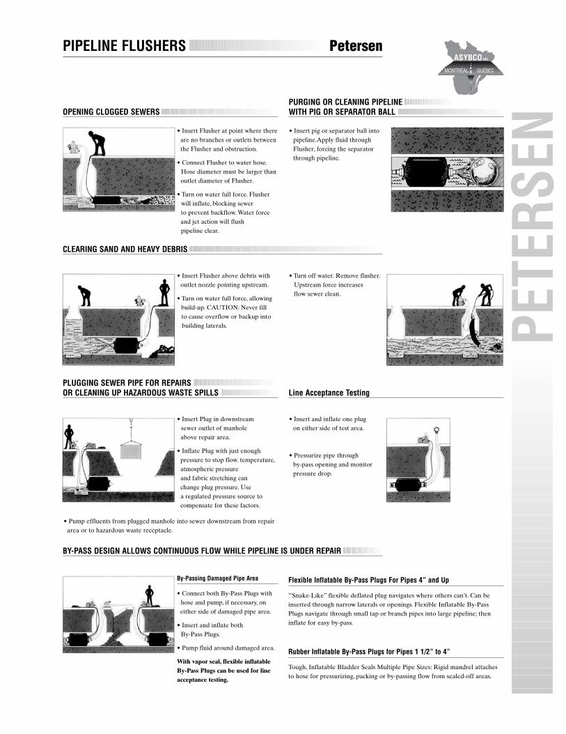
PLUGGING SEWER PIPE FOR REPAIRS OR CLEANING UP HAZARDOUS WASTE SPILLS Line Acceptance Testing
OPENING CLOGGED SEWERSPURGING OR CLEANING PIPELINEWITH PIG OR SEPARATOR BALL
PIPELINE FLUSHERS Petersen
• Insert Flusher at point where thereare no branches or outlets betweenthe Flusher and obstruction.
• Connect Flusher to water hose.Hose diameter must be larger thanoutlet diameter of Flusher.
• Turn on water full force. Flusher will inflate, blocking sewer to prevent backflow. Water force and jet action will flush pipeline clear.
• Insert Flusher above debris with outlet nozzle pointing upstream.
• Turn on water full force, allowingbuild-up. CAUTION: Never fill to cause overflow or backup intobuilding laterals.
• Insert Plug in downstream sewer outlet of manholeabove repair area.
• Inflate Plug with just enoughpressure to stop flow. temperature,atmospheric pressure and fabric stretching canchange plug pressure. Use a regulated pressure source tocompensate for these factors.
By-Passing Damaged Pipe Area
• Connect both By-Pass Plugs withhose and pump, if necessary, oneither side of damaged pipe area.
• Insert and inflate both By-Pass Plugs.
• Pump fluid around damaged area.
With vapor seal, flexible inflatableBy-Pass Plugs can be used for lineacceptance testing.
• Insert pig or separator ball intopipeline.Apply fluid throughFlusher, forcing the separatorthrough pipeline.
• Turn off water. Remove flusher.Upstream force increasesflow sewer clean.
• Insert and inflate one plugon either side of test area.
• Pressurize pipe through by-pass opening and monitorpressure drop.
Flexible Inflatable By-Pass Plugs For Pipes 4” and Up
“Snake-Like” flexible deflated plug navigates where others can’t. Can beinserted through narrow laterals or openings. Flexible Inflatable By-PassPlugs navigate through small tap or branch pipes into large pipeline; theninflate for easy by-pass.
Rubber Inflatable By-Pass Plugs for Pipes 1 1/2” to 4”
Tough, Inflatable Bladder Seals Multiple Pipe Sizes: Rigid mandrel attachesto hose for pressurizing, packing or by-passing flow from sealed-off areas.
CLEARING SAND AND HEAVY DEBRIS
BY-PASS DESIGN ALLOWS CONTINUOUS FLOW WHILE PIPELINE IS UNDER REPAIR
• Pump effluents from plugged manhole into sewer downstream from repair area or to hazardous waste receptacle.
PETE
RSEN

VITRE GLASS PLASTIFIÉE PLASTIC
BOOM SWIVELRotating Seal Bearings
• BS 6’’ is constructed to accomodate 6’’ & 10’’ standard 150# flanges.
• BS 8’’ PW has no bolts and is for welding 8’’ schedule 10 pipe on each side, request separate sheet.
• BS 8’’ replaces a 200 mm ID italian made swivel by using an optional adapter spacer.
• BS 17’’ G is the gear type, 105 teeth module 6, and optional pinion gear with 17 teeth.
• High carbon steel • Hardened raceways• Chromed bearing balls • O ring type seals• Gear drive available
ASYB
CO
VITRE DE NIVEAU SIGHT GLASS
Vue de Face / Top View Vue de Côté / Side View
Size G no. of Holes H1 No. of Holes
And AØ BØ C D EØ FØ GØ + Size Clearance Capacities
Type of Thread or Thread
BS 6” - 10 16.00 6.75 2.00 1.88 11.25 14.25 9.50 8 - 3/4 NC 12 - 1” 14.8 kNm
BS 6” - 6 13.00 6.25 3.50 N/A N/A 9.50 9.50 8 - 3/4 NC 8 - 3/4 NC 14.8 kNm
BS 8” PW11.50 8.33 3.38 N/A N/A N/A N/A N/A N/A 1.5 kNm
BS 8” 14.00 7.88 2.00 1.50 10.50 12.60 9.25 12 - 1/2 NC 12 - 0.58 7.3 kNm
BS 10” 16.25 10.00 2.00 1.62 12.77 15.00 11.38 12 - 1/2 NC 16 - 0.56 10.0 kNm
BS 12” 20.40 12.00 2.20 1.75 16.36 19.29 13.07 24 - 5/8 NC 12 - 7/8 NC 21.2 kNm
BS 17” 25.50 17.09 2.20 1.75 21.48 24.41 18.19 14 - 3/4 NC 10 - 0.79 48.6 kNm
BS 17” G 24.20 17.09 2.20 1.75 21.48 23.23 18.19 14 - 3/4 NC 14 - 3/4 NC 51.0 kNm
ASSEMBLÉ
Vitre
Joint torique
Base
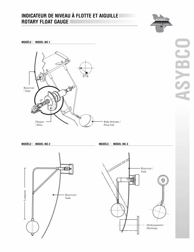
Balle flottante /Float ball
Disques/ Discs
Lon
gueu
r
Réservoir /Tank
Réservoir / Tank
Réservoir / Tank
Déchargement /Discharge
MODÈLE MODEL NO.2 MODÈLE MODEL NO.3
INDICATEUR DE NIVEAU À FLOTTE ET AIGUILLEROTARY FLOAT GAUGE
MODÈLE MODEL NO.1
ASYB
CO

SPHÈRE SANS UNIONSpherical Float, No Connection
SPHÈRE AVEC UNION INTÉRIEUR SIMPLESpherical float, single internal connection
CYLINDRE AVEC UNION EXTÉRIEUR SIMPLECylindrical float single external connection
External Hex
SPHÈRE À TUBE DIAMÉTRALSpherical Float, thru Tube
6’’ diamètre, 1/2’’ I.D. Tube 6’’ diameter, 1/2’’ I.D. Tube8’’ Diamètre, 1/2’’ I.D. Tube 8’’ Diameter, 1/2’’ I.D. Tube
COLONNE AVEC UNION EXTÉRIEURE DOUBLEColumn float double external connection
FORMES Shapes
Voici les modèles de balles de flottaison les plus populaires.La forme sphérique est la plus en demande. Autres modèles sur demande.
Below are some of the more popular float/tank shapes. Spherical are normally the most economical design.Custom design floats on request.
JOINTS SeamsLe joint est le point d'assemblage des deux demi-sphères.Ci-dessous, quelques exemples de joints disponibles selon la dimension, le format et le calibre de la balle.
• Joint à franc bord • Joint à petit rebord • Joint à rebord dominant
The seam is the point at which the two float halves are welded together. One or more of the seam designs shown below will be available to you depending on the size, gauge, and shape of the float you require.
• Butt Joint • Small Seam Standing • Seam
MATÉRIAUX Material
Acier Inoxydable 304 ou 316. Également disponibles sur demande,acier:
The majority of floats are manufactured out of 304 or 316 stainlesssteel. Other types of metal may be specified such as:
• 321 • 347 • Hasteloy C• Carpenter 20 • Monel • etc.
Avec certifications lorsque requisMaterial certification on all metals are available on request.
Diamètres disponibles / Diameters :
3’’, 3.5’’, 4’’, 5’’, 6’’, 7’’, 8’’, 9’’, 10’’, 12’’, 14’’.
BALLES DE FLOTTAISON EN ACIER INOXYDABLESTAINLESS STEEL FLOAT BALLS
ASYB
CO
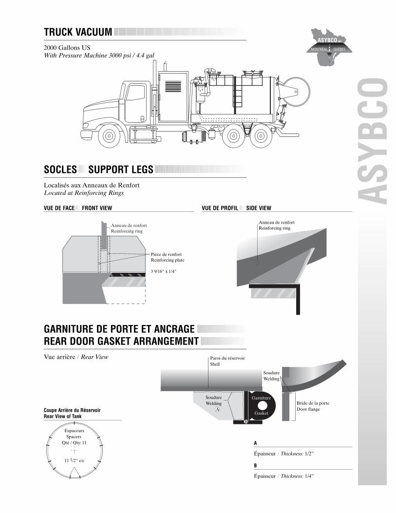
Anneau de renfortReinforcing ring
Pièce de renfortReinforcing plate
3 9/16" x 1/4"
Anneau de renfortReinforcing ring
Paroi du réservoirShell
A
B
Garniture
Gasket
SoudureWelding
SoudureWelding
Bride de la porte Door flange
EspaceursSpacers
Qté / Qty: 11
11 1/2" c/c
GARNITURE DE PORTE ET ANCRAGEREAR DOOR GASKET ARRANGEMENTVue arrière / Rear View
ASYB
CO
TRUCK VACUUM2000 Gallons USWith Pressure Machine 3000 psi / 4.4 gal
VUE DE FACE FRONT VIEW VUE DE PROFIL SIDE VIEW
SOCLES SUPPORT LEGSLocalisés aux Anneaux de RenfortLocated at Reinforcing Rings
A
Épaisseur / Thickness: 1/2”
B
Épaisseur / Thickness: 1/4”
Coupe Arrière du RéservoirRear View of Tank

LUBE-NUT5/8 - 11 thread
ASYB
CO C
A
B D
A
1.09”
B
2.17”
C
5.56”
D
3.25”
PORTALSCarbon Steel - ASME Code • Gasket On Lid • 40 p.s.i. mawp
Description Part Number A B C D E F (Qty) G Weight12” Portal - 6” Neck FC-800 12 7/8 6 20 3 1/2 1/4 4 9 3/4 4212” Portal - 12” Neck FC-800-1 12 76/8 12 20 9 1/2 1/4 4 15 3/4 58
MANWAYSCarbon Steel - ASME Code • Gasket On Lid • 40 p.s.i. mawp
Description Part Number A B C D E F (Qty) G Hinge Weight
20” Manway - 6” Neck FC-701-1 20 1/4 6 27 3 1/2 1/4 6 9 3/4 Std. 74
20” Manway - 12” Neck FC-701-2 20 1/4 12 27 9 1/2 1/4 6 15 3/4 Std. 101

VUE ARRIÈRE REAR VIEW VUE DE CÔTÉ SIDE VIEW
ASYB
COA
B
C
OUVERTURE DE PORTE ARRIÈRE REAR DOOR OPENING ASSEMBLY
MAIN DE SERRAGE WING NUT
A
Main de serrageWing nut
B
Bloc flottantFloating bloc
C
Boulon avec tige filetéeBolt
Tension de paroiTank lug shell
Tension de pivot deporteTank lug head

ASYB
COAsybco DOT VACUUM TANK
3200 IG
Asybco VACUUM TANK3000 IG + 500 IG
VUE DE CÔTÉ SIDE VIEW
VUE DE FACE FRONT VIEW
VUE ARRIÈRE REAR VIEW
VUE DE CÔTÉ SIDE VIEW
VUE ARRIÈRE REAR VIEW

CUSC
O
A
SYBC
OGallons
3200 IG
Dimensions prisent centre en centre
All dimension taken are center to center
A
Paroi réservoir / Shell tank:1/4”
B
Plaque de renfort / Overlap metal sheet:5/16” x 10 1/2”
C
Épaisseur porte / Thickness door:5/16”
CUSCO
Gallons
14’ - 3000 IG15’ - 3200 IG
Non DOT Coded
Dimensions prisent centre en centre
All dimension taken are center to center
A
Paroi réservoir / Shell tank:1/4”
B
Épaisseur porte / Thickness door:5/16”
RÉSERVOIR VACUUMVACUUM TANK
ASYBCO
14'De joint à jointSeam to seam
Anneaux de RenfortReinforcing ring
Qté / Qty: 5
BA C
14'De joint à jointSeam to seam
Anneaux de RenfortReinforcing ring
Qté / Qty: 2
BA
15'De joint à jointSeam to seam
78"
Anneaux de RenfortReinforcing ring
Qté / Qty: 5
BA C
Gallons
3000 IG
Dimensions prisent centre en centre
All dimension taken are center to center
A
Paroi réservoir / Shell tank :1/4”
B
Plaque de renfort / Overlap metal sheet:5/16” x 10 1/2”
C
Épaisseur porte / Thickness door:5/16”

25"
144"
10"3 1/2"
25"
16"
10 1/4"
Fils électricitépour lumières
Space for wiresfor lights
8" Pipe 6" Pipe
39 3/4"
7 3/4"
3"
FRUITLAND COUVERCLE LIDPour Filtre Primaire et Secondaire / For Primary and Secondary FilterFR
UITL
AND
ASY
BCO
COMPARTIMENTS POUR BOYAU SIDE TRAYSNuméros de Model / Model No.: F1016407
STRUCTURE DE BASE FRAME
VUE DE CÔTÉ SIDE VIEW VUE AVANT FRONT VIEW
VUE DE HAUT TOP VIEW VUE DE CÔTÉ SIDE VIEW
VUE AVANT FRONT VIEW
TUYAU DE CHARGEMENT SANDPIPEPour Filtre Primaire / Primary Shut-off Nozzle Detail

ÉCUREUR D’ÉGOUT
ASYB
CO
SPECIFICATIONSCapacité du réservoir 1500 gallon imp.
Matériel & épaisseur Bouts A36 / .187 Paroie A36 / .140
Diamètre du réservoir 66” pcs
Chambre de sedimentation Protection de la pompe. Tamis facilement accessible pour le nettoyage
Plaque de retenue (2 fois) 3/16” d’épaisseur
Peinture Epoxy à l’intérieur du réservoir
Trou d’homme 20” sur le dessus du réservoir. Approprié pour l’inspection & l’accès dans le réservoir.
Drainage Le réservoir est incliné de 2” pcs sur sa longueur pour faciliter le drainage
vers une valve en bronze de 2” à cet effet.
Système de remplissage 2 1/2” avec dispositif anti-syphon situé du côté droit avec boyau
d’une longueur de 25’ x 2 1/2” et raccord pour bouche à incendie.
Compartiments de rangement À la longueur du réservoir soudés à celui-ci.
Coffres à outils 2 coffres servent aux rangements de petits outils.
Échelle en acier Accès au dessus du réservoir du côté droit.
Alarme de recul Standard sur chaque unité.
Indicateur de niveau Tube de 2” pcs transparent situé à l’arrière ainsi qu’un alarme pour bas niveau.
Pompe à l’eau Marque Myers Capacité 65 gals / min à 2000 PSI
Modèle D 6520 Régulateur ajustable valve 25 à 70 GPM / 600 à 2000 PSI
Tuyauterie Du réservoir à la pompe en 3” et de la pompe au dévidoir et retour au réservoir en 1 1/4”
Un accouplement à air Purgation de l’eau du système.
Système hydraulique Pompe 42 GPM / 5000 PSI Réservoir hydraulique de 45 gallons imp.
Filtre & valve de relâche Refroidisseur d’huile
Moteur hydraulique & accouplement
Dévidoir Situé à l’arrière, 320o de rotation. Capacité de 600’ de boyau 1”. Vitesse variable dans les deux directions
avec la puissance suffisante pour ramener le boyau lorsque le système est opérant.
Boyau 1” x 500’, capacité d’opération à 2500 PSI, éclatement 6250 PSI
Contrôle & Jauges Révolution du moteur ajustable Alarme de bas niveau
Contrôle manuel des valves Contrôle de vitesse du dévidoir
Engagement de la pompe hydraulique (cabine) Compte-tours du moteur
Jauge pour la pression d’eau
Éclairage DOT avec le filage dans un tube de plastique
Peinture Sablage au jet de sable Peinture une couleur au choix du client
Accessoires standard Boyau flexible de 1” x 10’ Guide avec compteur de pieds
Pistolet avec 25’ de boyau 1/2” Régulateur ajusté à 800 lbs
Buse de 35o & 15o, 1” NPT Système de recirculation lors de température froide
Manuel de service & pièces
Installation Sur camion de C.A. 108” min. de capacité d’essieux de:
- 10000 lbs avant 23000 lbs arrière HP: 190 minimum

Plaques de renfortReinforcing plate
Fer angleSteel angle
Paroi + plaques de retenue Shell + Baffles
FondBottom
ProfilŽs en "T"Channel
144"
4" Dia.
69"
96"
Plaques de renfortReinforcing plate
Trou / Hole: 6" Dia
4" Dia.
78"
72"
Plaques de renfortReinforcing plate
Compartiment pour rangementTool box
Trou / Hole: 6" dia
Plaques de renfortReinforcing plate
Fer angleSteel angle
Paroi + plaques de retenue Shell + Baffles
FondBottom
Profilés en "T"Channel
96"
ÉCUREUR D’ÉGOUT SEWER CLEANER3737 Gallons I • 4488 USG
VUE GÉNÉRALE ASSEMBLY VIEW
ÉCUREUR D’ÉGOUT SEWER CLEANER1196 Gallons I • 1436 USG
ASYB
CO
VUE GÉNÉRALE ASSEMBLY VIEW
VUE ARRIÈRE REAR VIEW
VUE ARRIÈRE REAR VIEW

ASYB
CO
PREMIER INDUSTRIAL BAGHOUSE SYSTEMSMastervac 4527
FEATURES
• Cyclonic filtration with Cyclonic Bag technology offers complete filtration for all materials.
• Positive displacement blower. 4600 CFM at free air, 27” Hg maximum vacuum.
• Dual mode, wet and dry material change over.• Available in DOT 407/412 configuration for transportation
of hazardous waste; also available as non-DOT.• Can be equipped with pressure unloading systems and Hepa
filtration for asbestos removal.• 0.250” SA 285C shell and head material.• Blower transfer case drive assembly.• Dual 12” S.S. float ball/cage assemblies with rubber seat.• One-touch switch operation for wet/dry mode change over.• Dual 8” cyclone with 20” side cleanout and bottom drain.
• Rotary float gauge assembly. • Hydraulic full opening rear door.• 20-ton hydraulic dump system.• Full length side trays.• DOT lighting. • Hydraulic vibrator.• 20” top manway. • Dual 12” silencers.• Baghouse access platform with safety railing.• 285 CFM pressure unloading system with hydraulic drive.• Dual baghouse air cannon cleaning system.• 58 removable snap in bag assemblies.• Moro AC3 pressure unloading system with pre-blower
filter assembly.• Hydraulic 8” boom assembly.• Dual cyclonic baghouse with 58 polyester bags and 20” side
cleanout and bottom drain.• Pre-blower inlet 100 micron SS filter element.• 6” suction/discharge valves.
Performance Data
Noise level dbA 6 ft. distance 95Maximum CFM 4 600Maximum vacuum Hg 27CFM @ 15” Hg 4 141Capacity cubic yards 15Required CA 204Required front axle 18 000Required rear axle 46 000Horsepower 350
PREMIER INDUSTRIAL BAGHOUSE SYSTEMSMastervac 3827DC
FEATURES
• Cyclonic filtration with Cyclonic Bag technology offers complete filtration for all materials. Single mode operation with acrylic coated bags.
• Positive displacement blower: 3800 CFM at free air, 27” Hg maximum vacuum.
• Hydraulic rear door locking assembly with 8” dry material loading port.
• Available in DOT 407/412 configuration for transportation of hazardous waste; also available as non-DOT.
• Hydraulic dumping cyclone/baghouse assembly with 14” diameter sidemount dual rear dump chutes.
• 0.250” SA 285C shell and head material• Blower transfer case drive assembly• 16” S.S. float disc assembly with rubber seat.• 14” diameter dual dump tube chutes with front cleanout ports.
• Full opening dumping cyclone with internal 16” S.S. float disc.• Control panel. • Pre-blower inlet filter element.• 6” suction/discharge valves. • Rotary float gauge assembly.• Hydraulic full opening rear door. • 20-ton hydraulic dump system.• Safety braces. • D.O.T. lighting.• Hydraulic vibrator. • 20” top manway.• Dual 12 silencers. • Baffle• Tank built to DOT 407/412 code • High pressure wash system.• 285 CFM pressure unloading system with hydraulic drive.• Baghouse air cannon cleaning system.• 10” dia. internal transfer tube with 8” dia. dry material loading port.• Air operated/spring closing valves.• Baghouse access platform with safety railing.• 42” diameter dumping baghouse with 29 acrylic dust bags.
Performance Data
Noise level dbA 6 ft. distance 95Maximum CFM 4 600Maximum vacuum Hg 27CFM @ 15” Hg 3 350Capacity cubic yards 15Required CA 180Required front axle 18 000Required rear axle 46 000Horsepower 30

ASYB
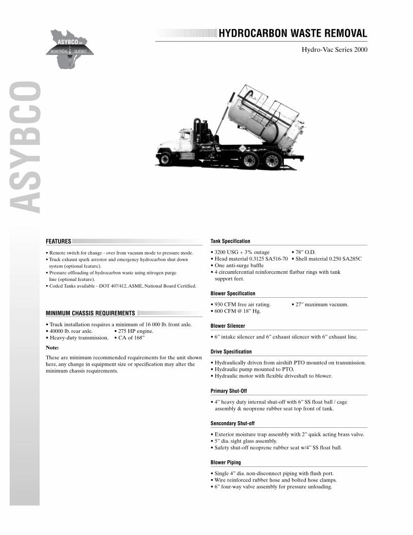
COHYDROCARBON WASTE REMOVAL
Hydro-Vac Series 2000
FEATURES
• Vacuum positive displacement blower.• Static ground discharge system.• Hydrocarbon exhaust muffler with hose connection for remote
exhaust disposal.• Nitrogen purge line for pressure offloading of hydrocarbon.• Truck exhaust spark arrestor.• Truck engine hydrocarbon emergency shutdown system.• DOT 407/412, A.S.M.E., National Board certified.• Air operated/spring closing suction and discharge valves.• High vacuum blower with intake/exhaust silencers.• Blower inlet filter assembly with remote control 4-way valve.• Optional high pressure wash system.• Air injection cooling - no vacuum relief.• No oil lubrication required.• Continuous vacuum 27” Hg 24 hours a day.• Hydraulically driven blower.• Nitrogen purge line for offloading hydrocarbon products.• Extended blower life; no frictional wear.• Oil free exhaust air, no oil catch required.
• Pressure unloading capability.• Truck engine hydrocarbon emergency shutdown system.• Static grounding system with truck exhaust spark arrestor.• Blower exhaust air scrubber with hose.• Work lights and safety beacons.• Shell and head material: 0.3125” SA516-70 carbon steel.• Full dump, 20-ton capacity cylinder.• PTO and hydraulic system with pressure relief valve.• 4” intake valve, 6” discharge valve.• Primary and secondary shut-offs.• Control panel. • 72” tank diameter.• Full opening rear door. • Tool box.• All vacuum/pressure plumbing. • Tank level gauge.• Top manway assembly. • Internal surge baffle.• DOT lighting. • Non-dumping hose trays.• Mud flaps. • DOT bumper.• Walkway with safety rail. • Fire extinguisher.• Body safety prop. • Door safety prop.
COMMERCIAL VACLow Profile
FEATURES
• Suitable for cleaning of underground parking, sport facilities and locations having low overhead requirements.
• Top mounted hose storage cage assembly.• Hydraulic dump system with 30” diameter rear door.• 650 USG capacity - rectangular profile 30” high, 60” wide,
.250 thickness.• Standard 318 CFM / 28” Hg vacuum pressure pump
& muffler assembly.• 3” intake with sand pipe deflector assembly.• 6” discharge valve.
• 20” top manway.• PTO pump drive system.• 4” suction valve.• Gauges.• Hydraulic drive.• Sight glasses.• Side trays.
Performance Data
Blower
Maximum CFM 800Maximum Hg 27CFM @ 15” Hg 640Cooling AirDrive Hydraulic

ASYB
CO
POWER VAC TRAILER SYSTEMSIndustrial VAC-130 Trailer
FEATURES
• DOT 407/412, A.S.M.E., National Board certified.• 1 000 to 9 000-gallon tank models available.• Transport hazardous material legally.• Compatible with most chassis driven wet line systems.• Single or dual hydraulic lift cylinders.• 130-barrel (5 460 U.S. gallon) tank, 0.250” SA285C carbon steelhead
and shell material.• 548 CFM liquid cooled rotary vane pump• Hydraulic motor, quick connect plumbing, valve body and
pressure relief valve• Primary and secondary shut-offs
• Air open/spring close DOT 407/412 approved intake and dis-charge valves, kamloks and caps.
• Full length 18” deep I-beam framing.• Liquid level indicator. • Muffler.• Hose trays, ladder, mud flaps. • DOT lights.• Vacuum pressure gauge. • Two baffles.• Acrylic urethane paint. • Reyco suspension.• Hayes Dana axles. • 11R x 22.5 tires.• Landing gear. • King pin.
Performance Data
Barrels 130Gallons 5 460Maximum CFM 750Maximum Hg 28”Max. Pres. Discharging 25 psiWeight (Empty) 28 500 lbAxle Capacity 22 500 lb eachWheels 20” dia 5-spokeWet System Required 40 gpm / 2 500 psiOverall Length 42 ft
TRAILER SYSTEMDual Hoist • 6000 I.G. Trailer
ASYB
COHYDROCARBON WASTE REMOVAL
Hydro-Vac Series 2000
FEATURES
• Remote switch for change - over from vacuum mode to pressure mode.• Truck exhaust spark arrestor and emergency hydrocarbon shut down
system (optional feature).• Pressure offloading of hydrocarbon waste using nitrogen purge
line (optional feature).• Coded Tanks available - DOT 407/412, ASME, National Board Certified.
MINIMUM CHASSIS REQUIREMENTS
• Truck installation requires a minimum of 16 000 lb. front axle.• 40000 lb. rear axle. • 275 HP engine.• Heavy-duty transmission. • CA of 168”
Note:
These are minimum recommended requirements for the unit shownhere, any change in equipment size or specification may alter theminimum chassis requirements.
Tank Specification
• 3200 USG + 3% outage • 78” O.D.• Head material 0.3125 SA516-70 • Shell material 0.250 SA285C• One anti-surge baffle• 4 circumferential reinforcement flatbar rings with tank
support feet.
Blower Specification
• 930 CFM free air rating. • 27” maximum vacuum.• 600 CFM @ 18” Hg.
Blower Silencer
• 6” intake silencer and 6” exhaust silencer with 6” exhaust line.
Drive Specification
• Hydraulically driven from airshift PTO mounted on transmission.• Hydraulic pump mounted to PTO.• Hydraulic motor with flexible driveshaft to blower.
Primary Shut-Off
• 4” heavy duty internal shut-off with 6” SS float ball / cage assembly & neoprene rubber seat top front of tank.
Sencondary Shut-off
• Exterior moisture trap assembly with 2” quick acting brass valve.• 5” dia. sight glass assembly.• Safety shut-off neoprene rubber seat w/4” SS float ball.
Blower Piping
• Single 4” dia. non-disconnect piping with flush port.• Wire reinforced rubber hose and bolted hose clamps.• 6” four-way valve assembly for pressure unloading.
ASYB
CO
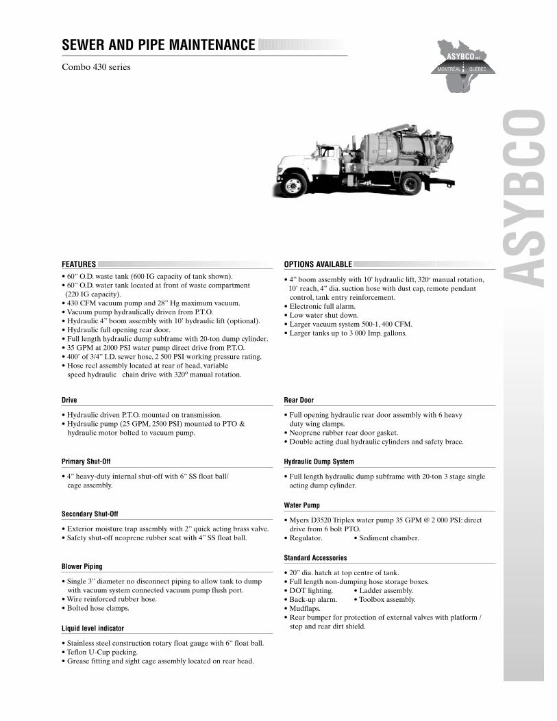
SEWER AND PIPE MAINTENANCECombo 430 series
Drive
• Hydraulic driven P.T.O. mounted on transmission.• Hydraulic pump (25 GPM, 2500 PSI) mounted to PTO &
hydraulic motor bolted to vacuum pump.
Primary Shut-Off
• 4” heavy-duty internal shut-off with 6” SS float ball/cage assembly.
Secondary Shut-Off
• Exterior moisture trap assembly with 2” quick acting brass valve.• Safety shut-off neoprene rubber seat with 4” SS float ball.
Blower Piping
• Single 3” diameter no disconnect piping to allow tank to dumpwith vacuum system connected vacuum pump flush port.
• Wire reinforced rubber hose.• Bolted hose clamps.
Liquid level indicator
• Stainless steel construction rotary float gauge with 6” float ball.• Teflon U-Cup packing.• Grease fitting and sight cage assembly located on rear head.
Rear Door
• Full opening hydraulic rear door assembly with 6 heavy duty wing clamps.
• Neoprene rubber rear door gasket.• Double acting dual hydraulic cylinders and safety brace.
Hydraulic Dump System
• Full length hydraulic dump subframe with 20-ton 3 stage single acting dump cylinder.
Water Pump
• Myers D3520 Triplex water pump 35 GPM @ 2 000 PSI: direct drive from 6 bolt PTO.
• Regulator. • Sediment chamber.
Standard Accessories
• 20” dia. hatch at top centre of tank.• Full length non-dumping hose storage boxes.• DOT lighting. • Ladder assembly.• Back-up alarm. • Toolbox assembly.• Mudflaps.• Rear bumper for protection of external valves with platform /
step and rear dirt shield.
FEATURES• 60” O.D. waste tank (600 IG capacity of tank shown).• 60” O.D. water tank located at front of waste compartment(220 IG capacity).
• 430 CFM vacuum pump and 28” Hg maximum vacuum.• Vacuum pump hydraulically driven from P.T.O.• Hydraulic 4” boom assembly with 10’ hydraulic lift (optional).• Hydraulic full opening rear door.• Full length hydraulic dump subframe with 20-ton dump cylinder.• 35 GPM at 2000 PSI water pump direct drive from P.T.O.• 400’ of 3/4” I.D. sewer hose, 2 500 PSI working pressure rating.• Hose reel assembly located at rear of head, variable
speed hydraulic chain drive with 320o manual rotation.
OPTIONS AVAILABLE
• 4” boom assembly with 10’ hydraulic lift, 320o manual rotation,10’ reach, 4” dia. suction hose with dust cap, remote pendant control, tank entry reinforcement.
• Electronic full alarm.• Low water shut down.• Larger vacuum system 500-1, 400 CFM.• Larger tanks up to 3 000 Imp. gallons.

ASYB
COPREMIER SITE REMEDIATION SYSTEMS
Turbovac Series
FEATURES
• Positive displacement blower: 2100 CFM to 4600 CFM, 27” Hg maximum vacuum.
• Single or dual cyclonic filtration with pre-blower inlet 100-micron SS filter element.
• Ideal for pickup and removal of liquids, slurries and bulk solid.• Available in DOT 407/412 configuration for transportation
of hazardous waste; also available as non-DOT.• Can be equipped with pressure unloading system.• Can be supplied in semi-trailer configuration.• Continuous operation at high vacuum levels.• No changeover required from wet to dry.• Re-useable, dry mode filter cleaning.• 0.250” SA 285C shell and head material.
OPTIONS AVAILABLE
• Tank built to DOT 407/412 code.• Air operated / spring closing valves.• High pressure wash system.• Blower transfer case drive assembly.• Polished stainless steel tank.• Spillbox. • Baffle.• Placard. • Work lights.• Rotating beacon. • Toolbox.• Static reel. • Fire extinguisher.• Hydraulic boom.
• Blower PTO / belt drive assembly with transmission oil cooler,2127
and 3127 models only, model 4527 transfer case drive assembly.• 12” SS float ball / cage assembly with rubber seat.• 8” diameter cyclone with 20” side cleanout and bottom drain.• Pre-blower inlet 100-micron SS filter element.• 6” suction discharge valves.• 285 CFM pressure unloading system with hydraulic drive.• 3500 USG tank capacity, 2127 and 3127 models, 3000 USG
tank capacity 4527 model.• Rotary float gauge assembly. • Hydraulic full opening rear door.• 20-ton hydraulic dump system.• Full length side trays.• DOT lighting. • Hydraulic vibrator.• 20” top manway. • Dual 10” silencers.
Performance Data
Turbovac Model 2127 3127 4527Maximum CFM Blower 2 100 3 100 4 600CFM @ 27” Hg Blower 438 540 1 958Max. Syst. Vacuum in Hg 28.5 28.5 28.5Max. Syst. Pressure PSI 25 25 25
Minimum Chassis Requirements
Turbovac Model 2127 3127 4527Clear CT 172” 180” 200”Front Axle 20 000 20 000 20 000Rear Axle 46 000 46 000 46 000Horsepower 300 300 350Transmission HD w/cooler HD w/cooler HD w/cooler

ASYB
CO
PREMIER INDUSTRIAL BAGHOUSE SYSTEMSMastervac 5327 DC
Tank
• 3000 U.S.G. + Outage (15 cu. yard) • Head material 0.3125 SA285-C• Shell material: 0.250 SA285C • Tank diameter: 78” O.D.
Blower
Hibon SIAV8702, 5300 CFM free air rating 27” Hg maximum vacuum.
Drive
Transfer case with airshift drive engagement mounted in truck drive-lines. Series 1710 blower driveline with guard.
Isolation Valves
Dual 8” air operated butterfly valves between primary shut-off andcyclone with PTO interconnect.
Primary Shut-Off
• 20” diameter manway assembly with heavy duty internal shut-off.• 14” SS float disc assembly and 12” rubber seat.• Dual 8” diameter flanged outlets with shear sections.
Filtration System
Single 42” diameter steel cyclone assembly, 14” diameter round dump tube running to rear of tank, swing up top access cover with hydraulic lift cylinder. Single steel rectangular baghouse assembly with 63 - 4” x 59” Acrylic coated bags, oil/moisture repellent, dual air cannon pulsation, system mounted on 14” round dump tube running to rear of tank with hydraulic lift cylinder, complete system to dump with tank.
Silencers
One 12” exhaust silencer, one 12” cooling intake silencers.
Blower Piping
Dual 8” diameter with 8” quick disconnect rubber boot assembly.
Blower Valving
6” butterfly manual vacuum relief valve and 12” inline check valve assembly.
Suction Valve
6” Betts air operated / spring closing valve with 6” sandpipe / deflectorassembly, aluminum kamlok fittings mounted on rear head.
Discharge Valve
6” Betts air operated / spring closing valve with aluminum kamlok fittings located bottom of rear head.
Hydraulic Dump System
31-ton, 110” stroke, 4-stage. Heavy-duty.
Vibrator
Heavy-duty hydraulic vibrator assembly mounted on bottom of tank,with speed control.
Hydraulic Reservoir
55 USG capacity with suction stainer, diffuser, fill breather cap,hydraulic oil filter and sight glass.
Hydraulic controls
5-spool valve body for control of hydraulic dump, rear door, cyclone and baghouse door, vibrator, rear door locks and vacuum / pressure off loading pump.
• Available in DOT 407/412 configuration for transportation of hazardous waste; also available as non-DOT.
• Can be equipped with pressure unloading systems and Hepa filtration for asbestos removal.

ASYB
COPROVEN SYSTEM FOR HAZARDOUS WASTE
Industrial VAC-70
FEATURES
• 548 CFM and 28” Hg liquid cooled pump.• DOT 407/412, A.S.M.E., National Board Certified.• Full hydraulic drive for all system functions.• Shell and head material: 0.3125” SA516-70 carbon steel.• PTO and hydraulic system with pressure relief valve.• 4” double intake valves, 6” double discharge valves.• 70 barrel (2940 U.S. gallons) tank. • Standard 20-ton hydraulichoist.• Top manway and spill box. • Standard full opening reardoor.• Full dump, 20-ton capacity cylinder. • All vacuum pressureplumbing.• 72” tank diameter. • Full opening rear door.• Internal surge baffle. • Tank level gauge.• DOT lighting. • Mud flaps.• Non-dumping hose trays. • Tool box.• Primary and secondary shutoffs. • DOT bumper.
OPTIONS AVAILABLE
• Tank sizes from 1000 to 4000 gals.• Walkway with safety rail.• High pressure wash system.• Vapor proof lighting.• Tank full alarm with siren.• Mechanical safety door lock.• Stainless steel tank, secondary shut-off, hose trays.• Hydraulic vibrator.
Performance Data
Maximum CFM 548Maximum Hg 28/93%CFM @ 15” Hg 488Cooling LiquidDrive Hydraulic
Minimum Chassis Requirements
Clear CT 156”Front Axle 16 000 lbRear Axle 40 000 lbHorsepower 240 HPTransmission Std. or Automatic
WASTE HANDLING UNIT2200 CFM
Liquid Ring Pump Arrangement
• Swivel Boom.• 500 IG Water Compartment.• Hydraulic Drive.• Pump is also available in 1100 CFM .• Dual Hoist.

ASYB
CO
TRAILER UNITBlower 3500 cfm • 6000 Gallons Vacuum Tank
1 Full opening hydraulic rear door 14 Complete control panel 27 6” sampling port2 Internal surge baffle 15 Turbovac model 3127 28 Cummins diesel engine3 20” dia. top manhole 16 Dropbox 29 Ladder4 20-ton hydraulic dump system 17 AC3 vacuum/pressure pump 30 Toolbox5 Hydraulic Vibrator 18 2” exterior moisture trap (second) 31 Hydraulic oil tank6 6” exhaust cyclone 19 10” check valve 32 Battery7 Primary shut-off 20 4” manual vacuum relief valve 33 2” no disconnect piping8 6” suction valve 21 6” air operated butterfly valve 34 Landind Gear9 6” discharge valve 22 2” air operated butterfly valve 35 Dot rear bumper10 20” dia. filter assembly 23 8” quick disconnect rubber boot 36 Bolt and handle assembly11 Rotary float gauge 24 Fender c/w mudflaps 37 Overturn protection12 8” exhaust silencer 25 2” pressure relief valve 38 Side box13 6” intake silencer 26 Spillbox 39 Exhaust muffler-oil trap
DOT 407 / 412500 IG
VUE DE HAUT VUE CÔTÉ CHAUFFEUR
ASYB
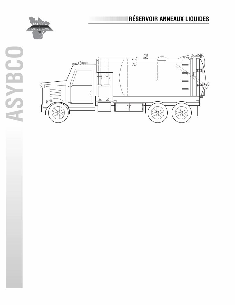
CORÉSERVOIR ANNEAUX LIQUIDES