INTER PHASE SPACERS
17
SUPREME & CO. PVT. LTD. INTER PHASE SPACERS
-
Upload
harish-agarwal -
Category
Engineering
-
view
169 -
download
7
Transcript of INTER PHASE SPACERS
SUPREME & CO. PVT. LTD.
INTER PHASE SPACERS
Over head lines (Transmission or Distribution) are always susceptible to swing due to wind. In areas with Ice loading , the problem becomes even more acute when the Ice starts melting which may give rise to galloping. The most effective way to handle the problem is deployment of Insulating devices or Inter Phase Spacers (IPS) between the Phases.
This phenomenon may also occur in bundle conductor system and in that case IPS find a good application.
The IPS restricts swing and galloping of conductors of adjacent phases there by achieving reduction of phase to phase clearance and compaction of line. Subsequently Right of Way (ROW) reduction.
In recent years use of IPS have increased significantly in order to make the transmission and distribution lines more compact and safe. This has been possible due to massive advancement and acceptance of composite insulators.
Composite inter phase separators have a great role to play to compact the lines and avoid flashovers & short circuits resulting from conductor swing and galloping.
INTRODUCTION TO COMPOSITE INTER PHASE SPACERS
The vast majority (92%) of the EVUs surveyed cited the main reasons for installation of Inter phase spacers as providing a solution to technical problems, such as:
Clashing conductors, in particular over long spans in the event of high winds and ice load or ice shedding.
Resultant short circuits, which in particular damage the strands in the outer layer of the conductor and also lead to an increase in radio interference.
Loose strands which then hang freely in the wind give rise to further short circuits. Clashing of the conductors during galloping, which occurs at high wind and with non-uniform icing of the conductors.
Avoiding flashover between the conductors in the span, since this is where the most intense galloping amplitudes occur.
Maintaining the necessary (electrical) clearances to earthed structures (for example towers).
Problems in obtaining rights of way for new line routes. At the time, line compaction as the reason for installing inter-phase spacers is only 4 %, which would
presumably be considerably higher nowadays as a result of the almost exclusive use of inter-phase spacers of composite design.
WHY Inter Phase Separators ?
OPERATIONAL EXPERIENCE
Conductor clashing caused by wind and non-uniform ice load were not encountered following installation of inter phase spacers.
Inter phase spacers proved to be a cost-effective alternative to installation of additional towers.
Inter phase spacers installed initially and made of porcelain were replaced with IPS of
composite design since the former had experienced mechanical failure.
The rigid attachment of IPS to the conductor failed under shock load (caused by galloping); this rigid design has been replaced by a flexible attachment technique.
Galloping could not be controlled completely, but conductor clashing and the associated conductor damage could be prevented. In addition, abrasion at the insulator coupling points and at the towers caused by galloping was able to be avoided.
No further flashover between the phases was observed following installation of IPS in
critical spans.
Mechanical Design of Inter Phase Spacers
More specifically, IPS are loaded dynamically primarily by Short circuit, due to conductor swing as well as for Ice shedding and Galloping. The respective forces have to be taken into account accordingly when dimensioning the IPS.
Inter Phase Spacers are mainly installed to control galloping hence various types of spacers can be adopted for the purpose. The spacers with different structure and structural parameters have different mechanical characteristics. The coupling action exists between the spacer and the conductor connected when the inter phase spacers are installed on the line. So different mechanical characteristics will lead to different effect of controlling galloping. In order to compare and optimize the mechanical parameter of spacer, we can classify the Inter phase spacers into three typical types.
Mechanical Model for Inter Phase Spacers
TYPES OF INTER PHASE SPACERS
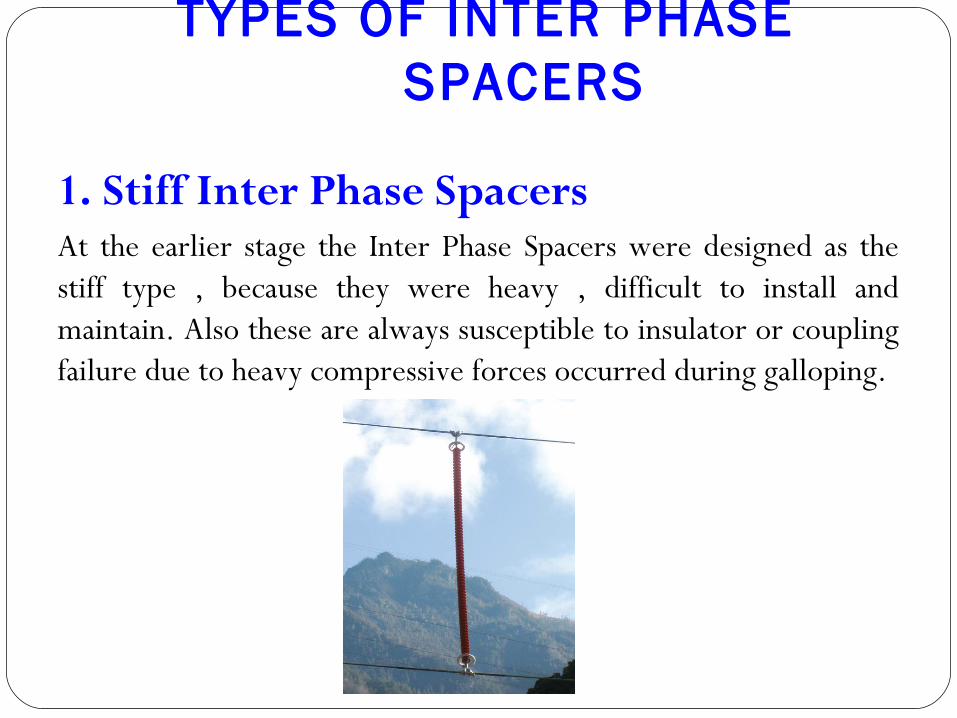
1. Stiff Inter Phase SpacersAt the earlier stage the Inter Phase Spacers were designed as the stiff type , because they were heavy , difficult to install and maintain. Also these are always susceptible to insulator or coupling failure due to heavy compressive forces occurred during galloping.
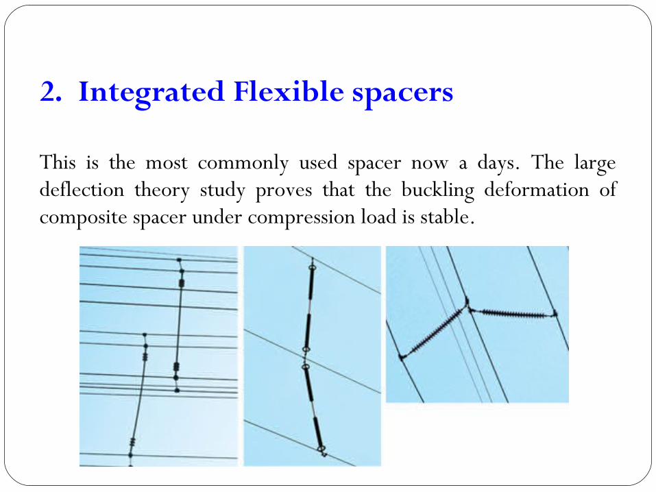
2. Integrated Flexible spacers
This is the most commonly used spacer now a days. The large deflection theory study proves that the buckling deformation of composite spacer under compression load is stable.
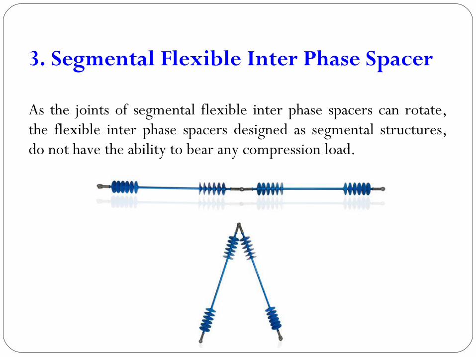
3. Segmental Flexible Inter Phase Spacer
As the joints of segmental flexible inter phase spacers can rotate, the flexible inter phase spacers designed as segmental structures, do not have the ability to bear any compression load.
Lay out Principles of inter phase spacers
Inter Phase composite spacers can control conductor galloping , because at both ends of the spacer were hung in an insulator, making the wiring point between the spacer and conductor easily becomes the node of conductor’s movement. The whole movement of conductor is closely related to elastic wave propagation within the conductor. Elastic wave becomes a reverse wave after reflection by the node, and it is helpful for controlling galloping.
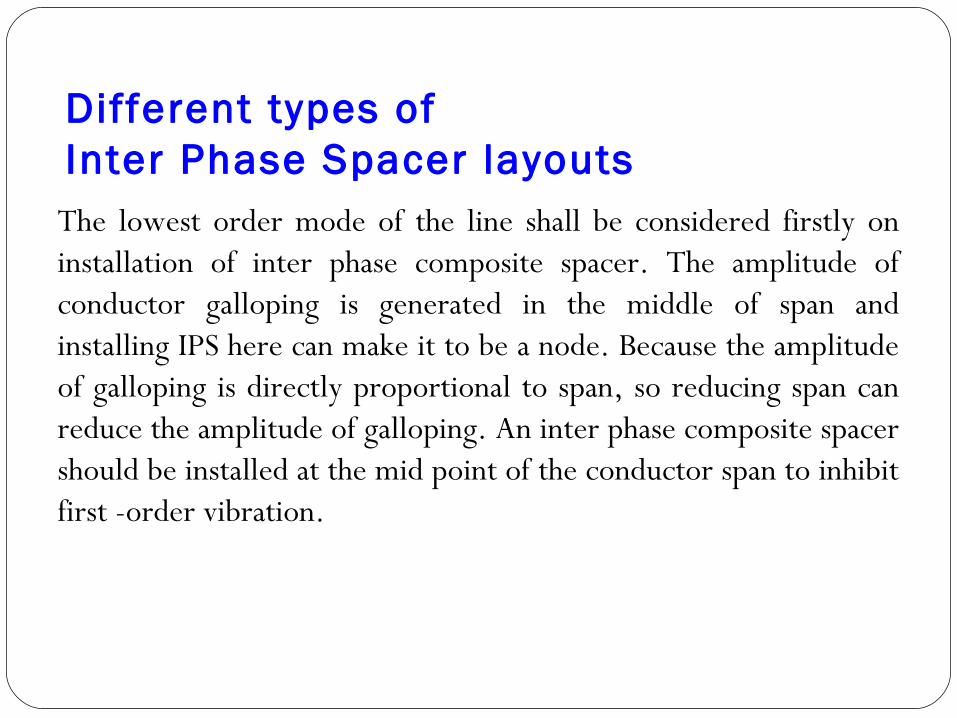
Different types of Inter Phase Spacer layouts
The lowest order mode of the line shall be considered firstly on installation of inter phase composite spacer. The amplitude of conductor galloping is generated in the middle of span and installing IPS here can make it to be a node. Because the amplitude of galloping is directly proportional to span, so reducing span can reduce the amplitude of galloping. An inter phase composite spacer should be installed at the mid point of the conductor span to inhibit first -order vibration.
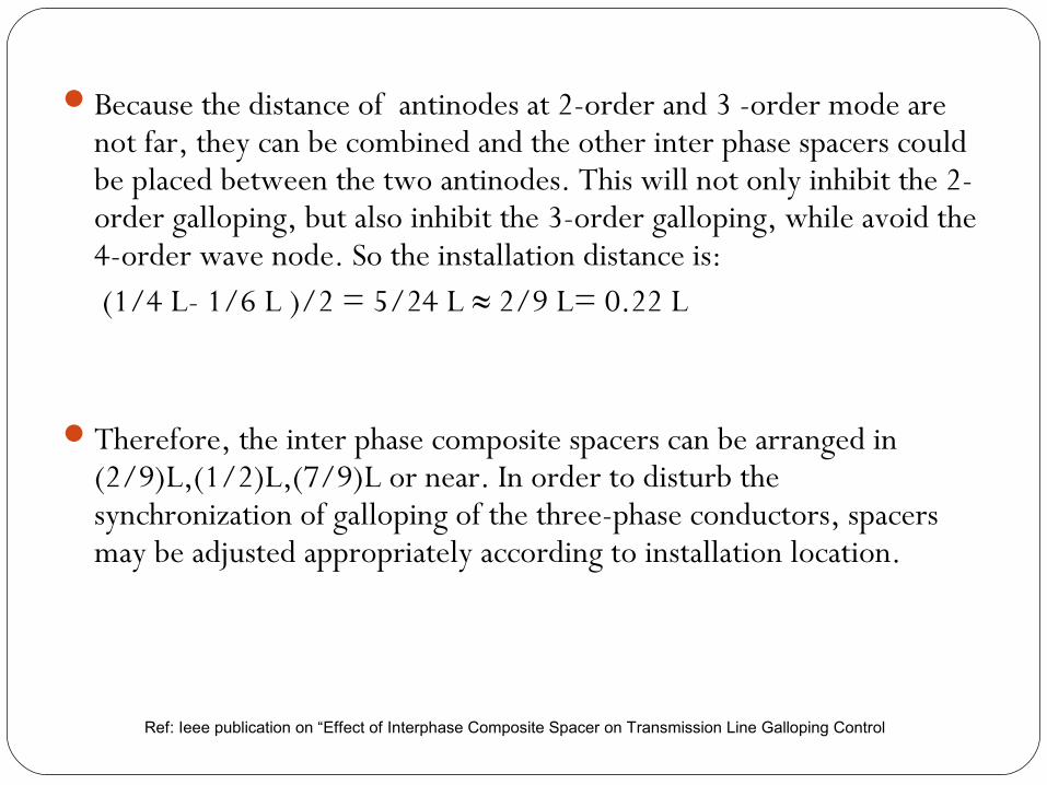
Because the distance of antinodes at 2-order and 3 -order mode are not far, they can be combined and the other inter phase spacers could be placed between the two antinodes. This will not only inhibit the 2-order galloping, but also inhibit the 3-order galloping, while avoid the 4-order wave node. So the installation distance is: (1/4 L- 1/6 L )/2 = 5/24 L ≈ 2/9 L= 0.22 L
Therefore, the inter phase composite spacers can be arranged in (2/9)L,(1/2)L,(7/9)L or near. In order to disturb the synchronization of galloping of the three-phase conductors, spacers may be adjusted appropriately according to installation location.
Ref: Ieee publication on “Effect of Interphase Composite Spacer on Transmission Line Galloping Control
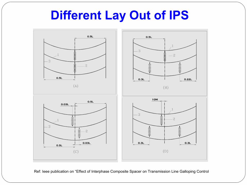
Different Lay Out of IPS
Ref: Ieee publication on “Effect of Interphase Composite Spacer on Transmission Line Galloping Control
Testing of Inter Phase Spacers
Testing of the Inter Phase Spacers depend basically upon two parameters depending upon the application. 1. Electrical Parameter 2. Mechanical Parameter Tests can be done to confirm the electrical parameters of the insulating part similar to the tests done on polymeric insulators as per IEC -61109 and other corresponding standards
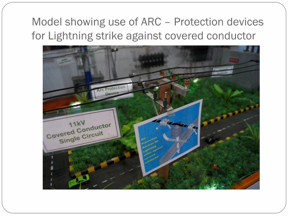
Model showing use of ARC – Protection devices for Lightning strike against covered conductor
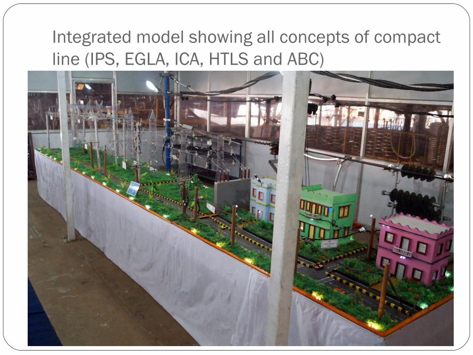
Integrated model showing all concepts of compact line (IPS, EGLA, ICA, HTLS and ABC)

THANK YOU…