Assoc. Prof. Dr. Yavuz YARDIM · Change load case type as moving load Then click on add to apply...
58
Assoc. Prof. Dr. Yavuz YARDIM Assoc. Prof. Dr. Yavuz YARDIM
Transcript of Assoc. Prof. Dr. Yavuz YARDIM · Change load case type as moving load Then click on add to apply...

Assoc. Prof. Dr. Yavuz YARDIM
Assoc. Prof. Dr. Yavuz YARDIM

Assoc. Prof. Dr. Yavuz YARDIM

Assoc. Prof. Dr. Yavuz YARDIM

Assoc. Prof. Dr. Yavuz YARDIM

Assoc. Prof. Dr. Yavuz YARDIM

Assoc. Prof. Dr. Yavuz YARDIM

Then click OK three times to close windows
Now we define the Layout
Next step will defining deck section
�Go to bridge
�Deck section
�Add new deck section
�Choose steel and concrete deck section ( Steel girder)
Now we have default section
we need to change girder section which is FSEC1
Assoc. Prof. Dr. Yavuz YARDIM

Assoc. Prof. Dr. Yavuz YARDIM
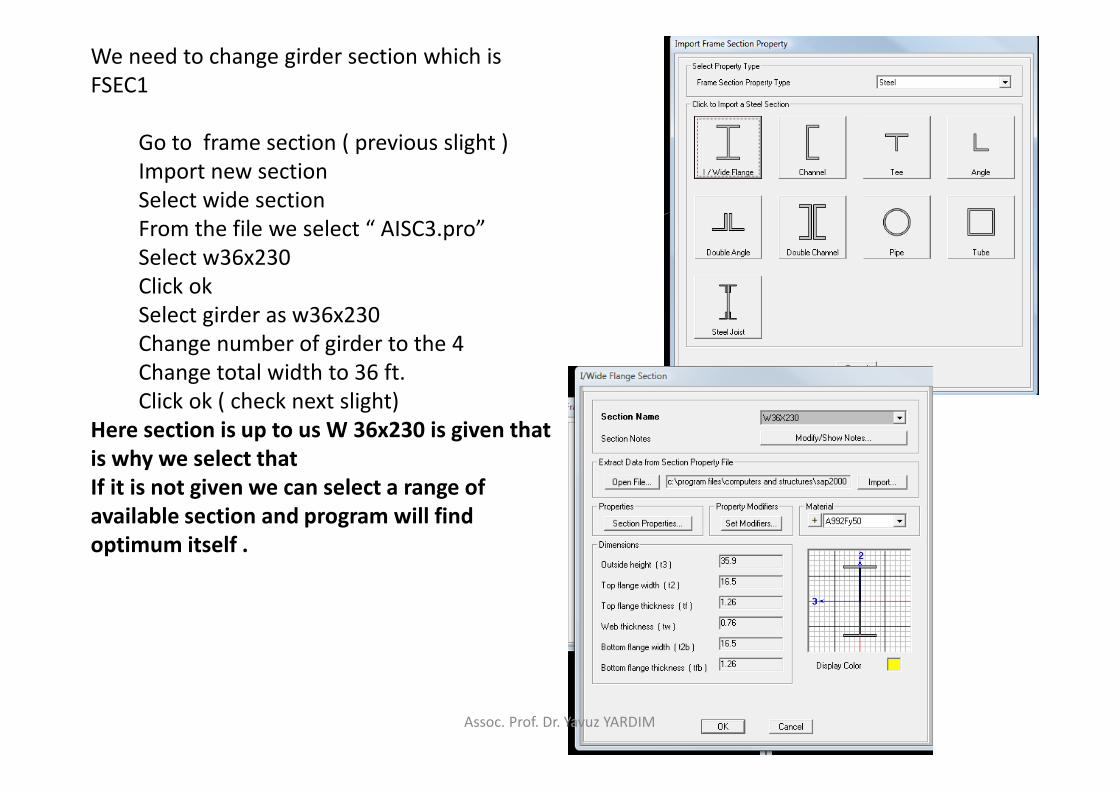
We need to change girder section which is
FSEC1
Go to frame section ( previous slight )
Import new section
Select wide section
From the file we select “ AISC3.pro”
Select w36x230
Click ok
Select girder as w36x230
Change number of girder to the 4
Change total width to 36 ft.
Click ok ( check next slight)
Here section is up to us W 36x230 is given that
is why we select that
If it is not given we can select a range of
available section and program will find
optimum itself .
Assoc. Prof. Dr. Yavuz YARDIM

Assoc. Prof. Dr. Yavuz YARDIM

Now we define diaphragms
�Go to bridge
�Diaphragms
�Add new diaphragm
�Select chord and brace
It is steel girder that is why we have to
select this for bracing this give us more
sound bridge
Include top chord press “+ “
Import new Properties
Select wide section
From the file we select “ AISC3.pro”
Select w8x10
Click ok
Select girder as w8x10 for all ( check the figure
in this slight)
Click ok two times
Assoc. Prof. Dr. Yavuz YARDIM
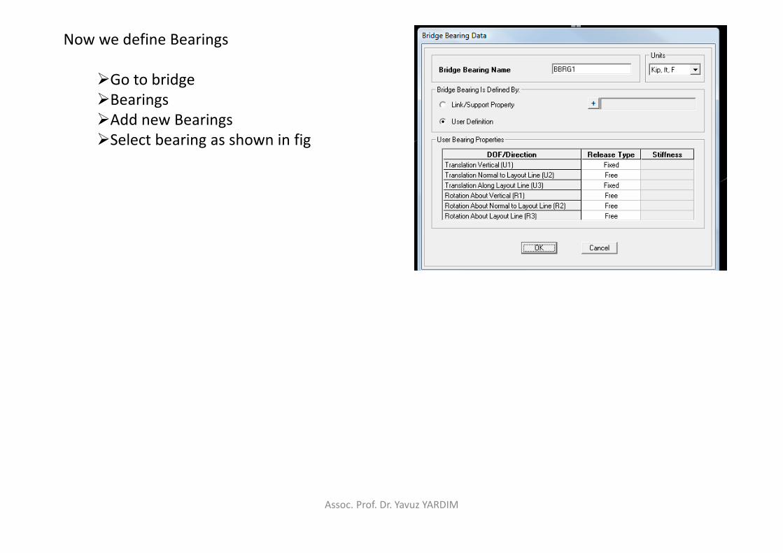
Now we define Bearings
�Go to bridge
�Bearings
�Add new Bearings
�Select bearing as shown in fig
Assoc. Prof. Dr. Yavuz YARDIM

Now we define foundation
�Go to bridge
�Foundation spring
�Add new Foundation spring
�Set the windows as in fig.
Assoc. Prof. Dr. Yavuz YARDIM
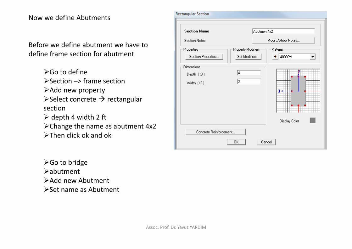
Now we define Abutments
Before we define abutment we have to
define frame section for abutment
�Go to define
�Section –> frame section
�Add new property
�Select concrete � rectangular
section
� depth 4 width 2 ft
�Change the name as abutment 4x2
�Then click ok and ok
�Go to bridge
�abutment
�Add new Abutment
�Set name as Abutment
Assoc. Prof. Dr. Yavuz YARDIM

Abutments
�Set windows as in figure
�Click ok two times and reach main
window
Assoc. Prof. Dr. Yavuz YARDIM
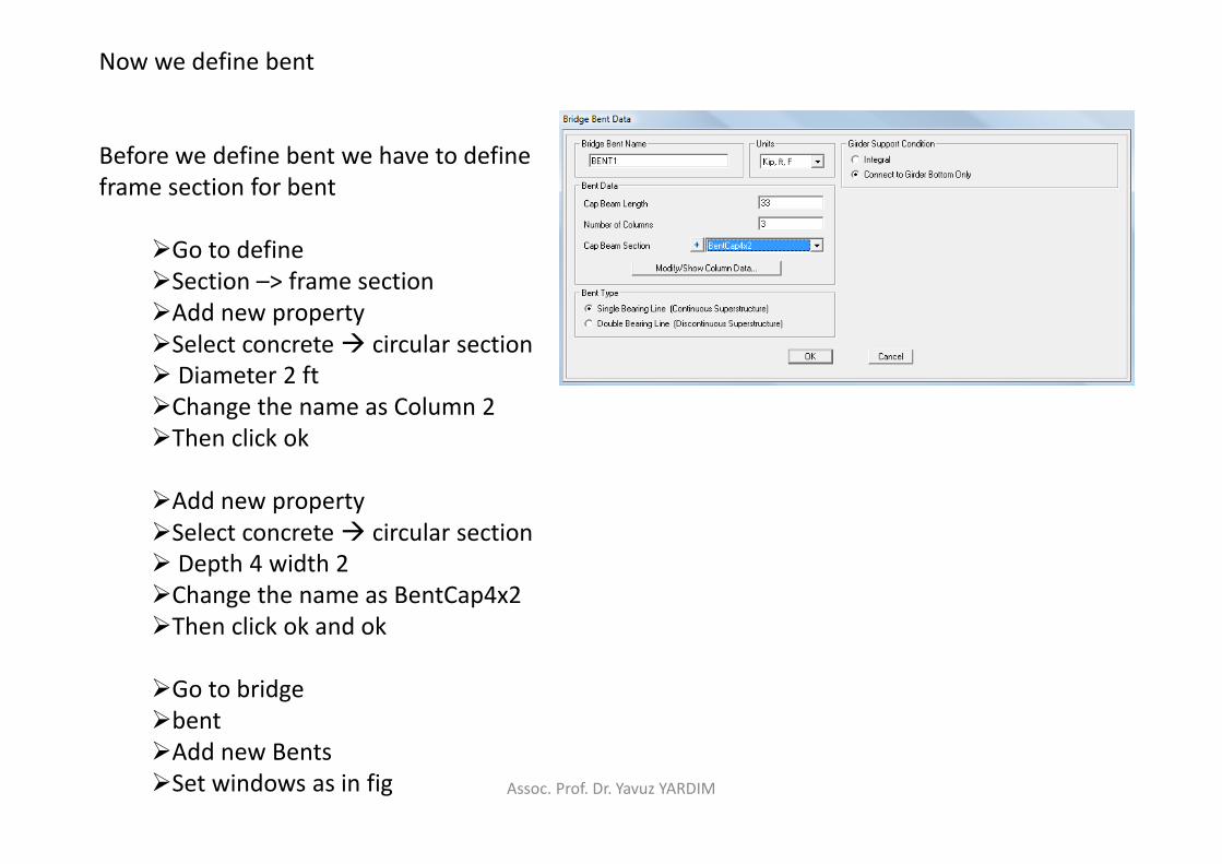
Now we define bent
Before we define bent we have to define
frame section for bent
�Go to define
�Section –> frame section
�Add new property
�Select concrete � circular section
� Diameter 2 ft
�Change the name as Column 2
�Then click ok
�Add new property
�Select concrete � circular section
� Depth 4 width 2
�Change the name as BentCap4x2
�Then click ok and ok
�Go to bridge
�bent
�Add new Bents
�Set windows as in fig Assoc. Prof. Dr. Yavuz YARDIM

Press modify/show column data
�Set windows as in figure
�Click ok and ok and ok
Assoc. Prof. Dr. Yavuz YARDIM

Now we define Bridge Object
This option will combine all predefined
bridge member in to a bridge structure
�Go to Bridge
�Bridge object
�Add new bridge Object
�Select span �
�start abutment 1000ft
�Press modify
�Click span end abutment
� end span 1100
�Press modify
�Type 1050 to station and press add
to add intimidate span (span1 )
�Be sure windows is set like in fig
�DON’T Click ok
Assoc. Prof. Dr. Yavuz YARDIM
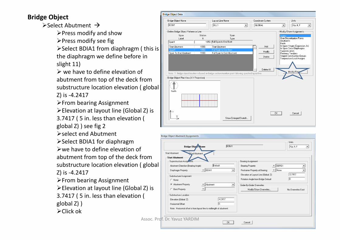
Bridge Object
�Select Abutment �
�Press modify and show
�Press modify see fig
�Select BDIA1 from diaphragm ( this is
the diaphragm we define before in
slight 11)
� we have to define elevation of
abutment from top of the deck from
substructure location elevation ( global
Z) is -4.2417
�From bearing Assignment
�Elevation at layout line (Global Z) is
3.7417 ( 5 in. less than elevation (
global Z) ) see fig 2
�select end Abutment
�Select BDIA1 for diaphragm
�we have to define elevation of
abutment from top of the deck from
substructure location elevation ( global
Z) is -4.2417
�From bearing Assignment
�Elevation at layout line (Global Z) is
3.7417 ( 5 in. less than elevation (
global Z) )
�Click ok
Assoc. Prof. Dr. Yavuz YARDIM

Bridge Object
�Select Bent �
�Press modify and show
�Select BDIA1 from
diaphragm ( this is the
diaphragm we define before in
slight 11)
� we have to define bent
location top of the deck from
bent location elevation ( global
Z) is -4.2417
�From bearing Assignment
�Elevation at layout line
(Global Z) is 3.7417 ( 5 in. less
than elevation ( global Z) ) see
fig
�Click ok
�Then ok and ok to go main
page
Assoc. Prof. Dr. Yavuz YARDIM
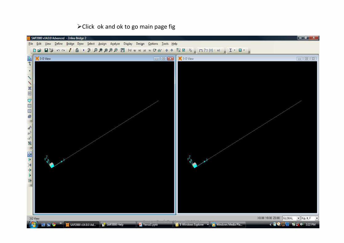
�Click ok and ok to go main page fig
Assoc. Prof. Dr. Yavuz YARDIM

Now we Link bridge model
�Go to Bridge
�Update linked bridge model
�Maximmum segment length for deck spans is 5
�Press update as Area Object model
�And click ok
Assoc. Prof. Dr. Yavuz YARDIM

Assoc. Prof. Dr. Yavuz YARDIM

�Click set displace option
�Click extrude view and click ok
�Close one of the windows
Assoc. Prof. Dr. Yavuz YARDIM

Assoc. Prof. Dr. Yavuz YARDIM

Check model with dead load
Go to Bridge �
Update Link bridge model
Update as spine model using frame objects
Assoc. Prof. Dr. Yavuz YARDIM

�Click set displace option
�Click extrude view and click ok
Assoc. Prof. Dr. Yavuz YARDIM

�Now bridge represented by line element
�Then run the analysis by click this
Assoc. Prof. Dr. Yavuz YARDIM

�Select the Modal and click do not run case
�And press run now
Assoc. Prof. Dr. Yavuz YARDIM

Assoc. Prof. Dr. Yavuz YARDIM

�Check bending moment diagram
�Press frames /cables
�Select moment 3-3
Assoc. Prof. Dr. Yavuz YARDIM

�Unlock the model by press this lock
Go to Bridge �
Update Link bridge model
Update as area object model
And run the analysis to see bending moment diagram for individual girder
Assoc. Prof. Dr. Yavuz YARDIM
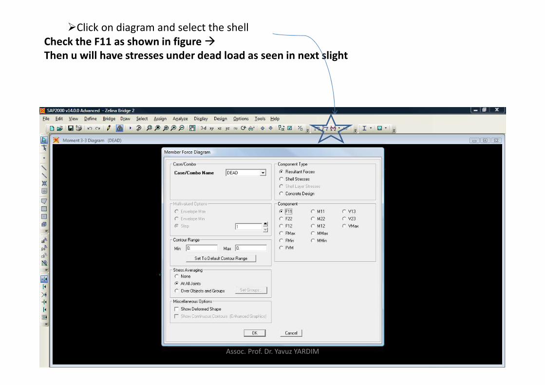
�Click on diagram and select the shell
Check the F11 as shown in figure �
Then u will have stresses under dead load as seen in next slight
Assoc. Prof. Dr. Yavuz YARDIM

Assoc. Prof. Dr. Yavuz YARDIM

�Now we will define live load
�Unlock the model by press lock
Go to Bridge �
Lane and add new bridge lane and add new lane defined from layout line
�Starting station is 1000 ft
�Center line offset is 8 ft
�And lane width is 12 ft
�And click add
�Click ok
Assoc. Prof. Dr. Yavuz YARDIM

�Click add copy of the lane
�Then enter -16 for center line offset
�Click ok and be sure that u have define lane 2 as shown in figure down
�if not u can enter values for the lane by manual one by one to obtain lane 2
�You can modify every
values by changing the
value then click on modify
�Be sure u have visible
color for lane , you can
change the color by this
button
Assoc. Prof. Dr. Yavuz YARDIM

�Go to display
�Then show lane
�Show lane width
�And be sure that u get figure below
Assoc. Prof. Dr. Yavuz YARDIM

�Now we define vehicles
�Go to bridge and vehicles
� select add vehicles
�And select HSn-44
�Then click convert to general vehicle
�Then click ok
�Click on modify /show button to see what is HSn 44
Assoc. Prof. Dr. Yavuz YARDIM

�HSn 44 shows two point load ( look the load plan ) and
�Different loading ( look the load elevation )
�You can play with values in table below to modify the loading
Assoc. Prof. Dr. Yavuz YARDIM

�We change the two point loads to line load
�Go to axis width type and select the fixed line width
�Then click on modify and do this for all three load
�Be sure u have figure below
Assoc. Prof. Dr. Yavuz YARDIM
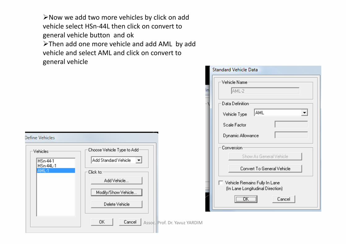
�Now we add two more vehicles by click on add
vehicle select HSn-44L then click on convert to
general vehicle button and ok
�Then add one more vehicle and add AML by add
vehicle and select AML and click on convert to
general vehicle
Assoc. Prof. Dr. Yavuz YARDIM

�Now define vehicle class
�Go to bridge and vehicle class
�Add new vehicle class and add three pre defined vehicle
�By this operation we place all the vehicles on the bridge as in fig
� press ok and ok
Assoc. Prof. Dr. Yavuz YARDIM

�Now load cases
�Go to define and load case
�Click on add new load case
�And type load case name as Move 1
�Change load case type as moving load
�Then click on add to apply load on the lane
�In other word we order the vehicles in the way we want on the bridge lane
Assoc. Prof. Dr. Yavuz YARDIM

�Now load combination
�Go to define and load combination
�Click on add new load combination
�Click on add button to add dead load
�And select Move 1 and click on add button to add moving load
�Press ok and ok
Assoc. Prof. Dr. Yavuz YARDIM
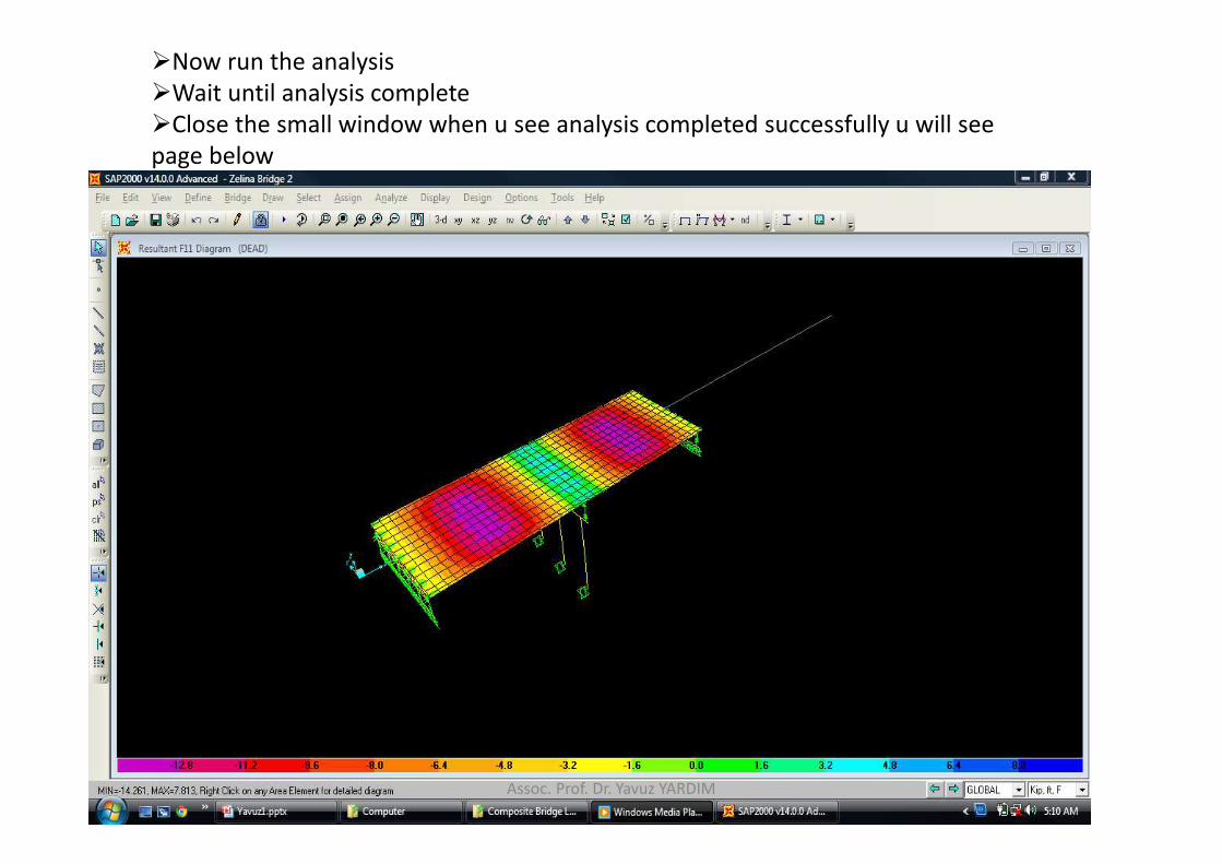
�Now run the analysis
�Wait until analysis complete
�Close the small window when u see analysis completed successfully u will see
page below
Assoc. Prof. Dr. Yavuz YARDIM

�Now u can get any results you want from display button
Assoc. Prof. Dr. Yavuz YARDIM

�Now unlock the model to see the load pattern for moving load
�Go to define and load pattern
�Type load pattern name as moving load and type as bridge live
�Click on add bridge load pattern on right side of the window
�Then click on modify the bridge live load as shown in fig below
Assoc. Prof. Dr. Yavuz YARDIM

�Add the vehicles one by one and obtain the final figure of the box as in fig
below then click ok
Assoc. Prof. Dr. Yavuz YARDIM

�Now we define an other load pattern name is move
�Click add and then modify to define vehicle order
� arrange the vehicle as in figure below
�Then press ok and ok
Assoc. Prof. Dr. Yavuz YARDIM

�Now we define the load cases
�Go to define and load cases
�And select moving load and press on modify/select load cases
� be sure it is multi step static
�Then click ok
Assoc. Prof. Dr. Yavuz YARDIM

�Now go to move load and select the time history from the load case type
�Select the direct integration for time history type
�And set the windows as shown below
Assoc. Prof. Dr. Yavuz YARDIM

�Click on the modify/show button next to damping
Assoc. Prof. Dr. Yavuz YARDIM

�Set the windows as in the figure below to define mass and stiffness proportion
damping
�Then press ok to close this window then press ok to close previous one then
press ok last time to reach general window
�Then run the analysis
Assoc. Prof. Dr. Yavuz YARDIM

Assoc. Prof. Dr. Yavuz YARDIM
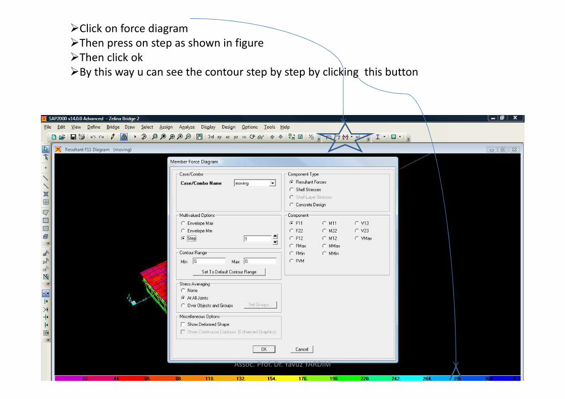
�Click on force diagram
�Then press on step as shown in figure
�Then click ok
�By this way u can see the contour step by step by clicking this button
Assoc. Prof. Dr. Yavuz YARDIM
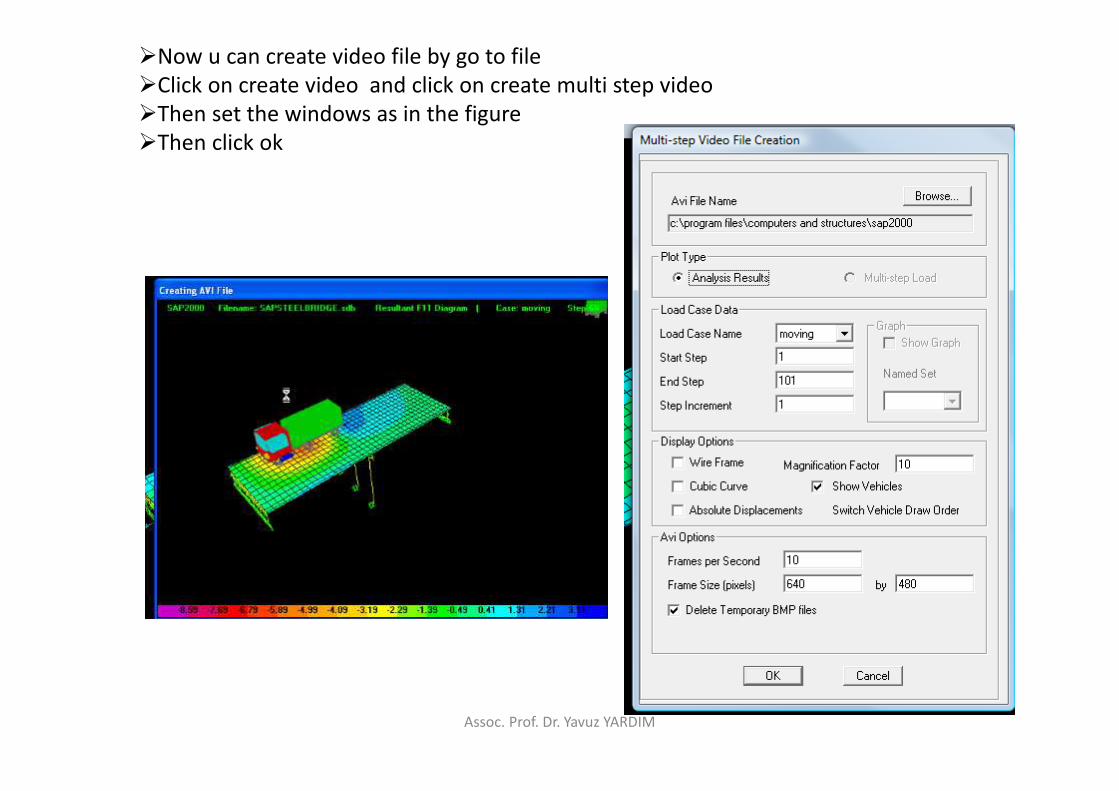
�Now u can create video file by go to file
�Click on create video and click on create multi step video
�Then set the windows as in the figure
�Then click ok
Assoc. Prof. Dr. Yavuz YARDIM
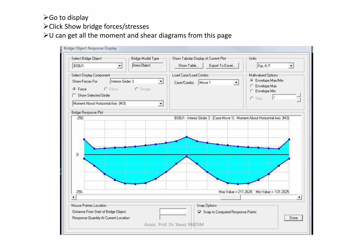
�Go to display
�Click Show bridge forces/stresses
�U can get all the moment and shear diagrams from this page
Assoc. Prof. Dr. Yavuz YARDIM

�Now u can get all the results of structure analysis of the bridge
Assoc. Prof. Dr. Yavuz YARDIM