Assoc. Prof. Dr. Ahmet Serdar TURK 1 GPR System and Operation Ultra-wide Band Antenna Designs ...
48
Assoc. Prof. Dr. Ahmet Serdar TURK 1 GPR System and Operation Ultra-wide Band Antenna Designs Landmine Detection by TUBITAK GPR Non-destructive Testing by GSSI Geo Radar GROUND PENETRATING RADAR
-
Upload
dario-trout -
Category
Documents
-
view
315 -
download
12
Transcript of Assoc. Prof. Dr. Ahmet Serdar TURK 1 GPR System and Operation Ultra-wide Band Antenna Designs ...
Assoc. Prof. Dr. Ahmet Serdar TURK 1
GPR System and Operation
Ultra-wide Band Antenna Designs
Landmine Detection by TUBITAK GPR
Non-destructive Testing by GSSI Geo Radar
GROUND PENETRATING RADAR
Assoc. Prof. Dr. Ahmet Serdar TURK 2
• Overview: What’s GPR?
• How does it work?
• System Description
• General Requirements
• RF Hardware: Transmitter/Receiver/Antenna Blocks
• Control and Software: Data/Signal Processing
GPR SYSTEM
Assoc. Prof. Dr. Ahmet Serdar TURK 3
GPR OPERATION
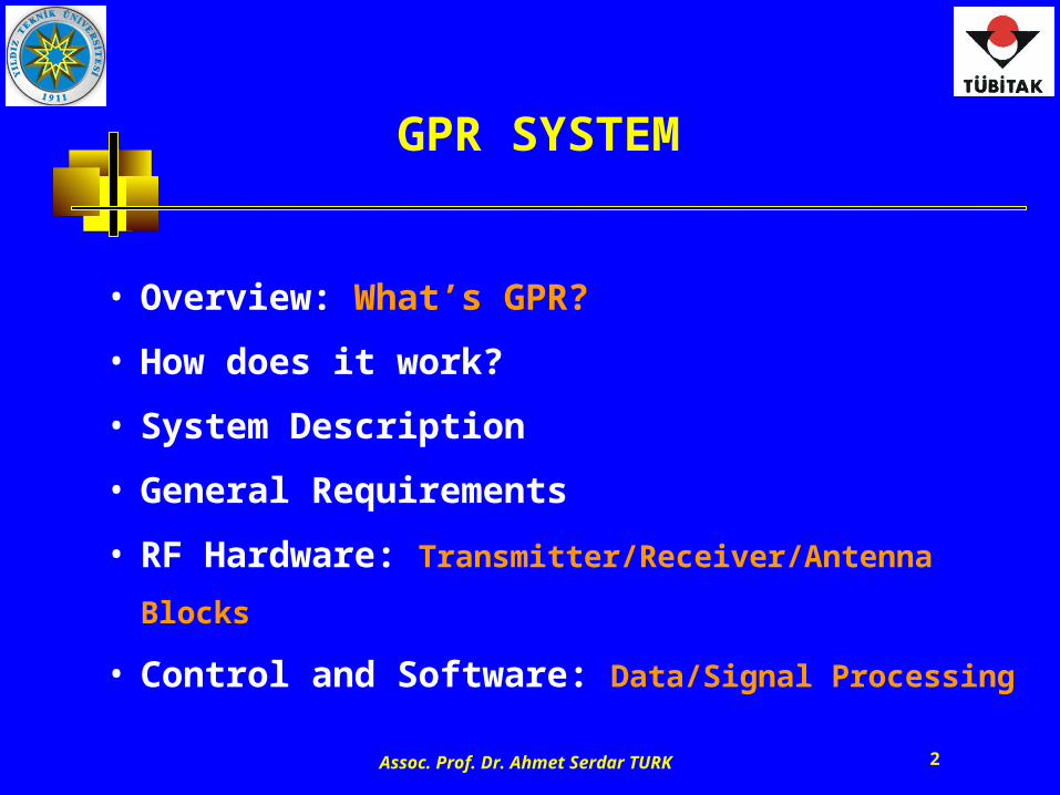
• Uses high frequency pulsed E.M. waves
• Particularly used in geo-technical, mining and archeological surveys
• Depth of penetration varies from less than a meter to over kilometers, depending on the material properties
• Higher scan and sampling rate
Impulse GPR Stepped-frequency GPR
• Uses high frequency swept or stepped continuous electromagnetic waves
• Operational frequency band is selectable depending on the required range resolution and penetration depth of the target
• Better dynamic range performance
• More complicated signal processing
• GPR is a near-zone electromagnetic radar system, which is used to detect, locate, identify and image subsurface objects• Ultra-wide band (UWB) operation is proposed to benefit both low and high frequencies that determines depth and resolution
Assoc. Prof. Dr. Ahmet Serdar TURK 4
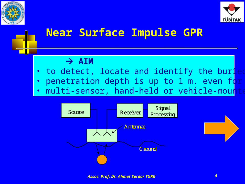
Near Surface Impulse GPR
AIM• to detect, locate and identify the buried objects/sub layers• penetration depth is up to 1 m. even for hard/wet ground• multi-sensor, hand-held or vehicle-mounted operation
Source
Receiver Signal
Processing
Antennas
Ground
Assoc. Prof. Dr. Ahmet Serdar TURK 5
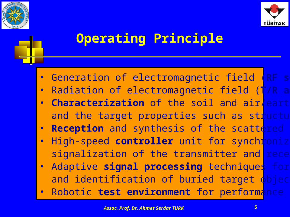
Operating Principle
• Generation of electromagnetic field (RF source)• Radiation of electromagnetic field (T/R antennas)• Characterization of the soil and air/earth interface,
and the target properties such as structure, shape, etc.• Reception and synthesis of the scattered RF fields• High-speed controller unit for synchronization and
signalization of the transmitter and receiver blocks• Adaptive signal processing techniques for detection
and identification of buried target objects• Robotic test environment for performance analysis
Assoc. Prof. Dr. Ahmet Serdar TURK 6
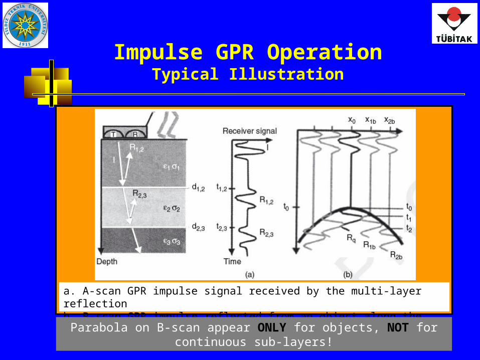
Impulse GPR OperationTypical Illustration
a. A-scan GPR impulse signal received by the multi-layer reflectionb. B-scan GPR impulse reflected from an object along the direction (see parabola shape)
Parabola on B-scan appear ONLY for objects, NOT for continuous sub-layers!
Assoc. Prof. Dr. Ahmet Serdar TURK 7
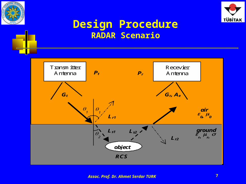
Design ProcedureRADAR Scenario
Recevier Antenna
Transmitter Antenna
object
ground
r, r, Ls1
Lr1
Ls2
Lr2
air
0, 0
Pt
Gt
Pr
Gr, Ae
RCS
1
1
2
Assoc. Prof. Dr. Ahmet Serdar TURK 8
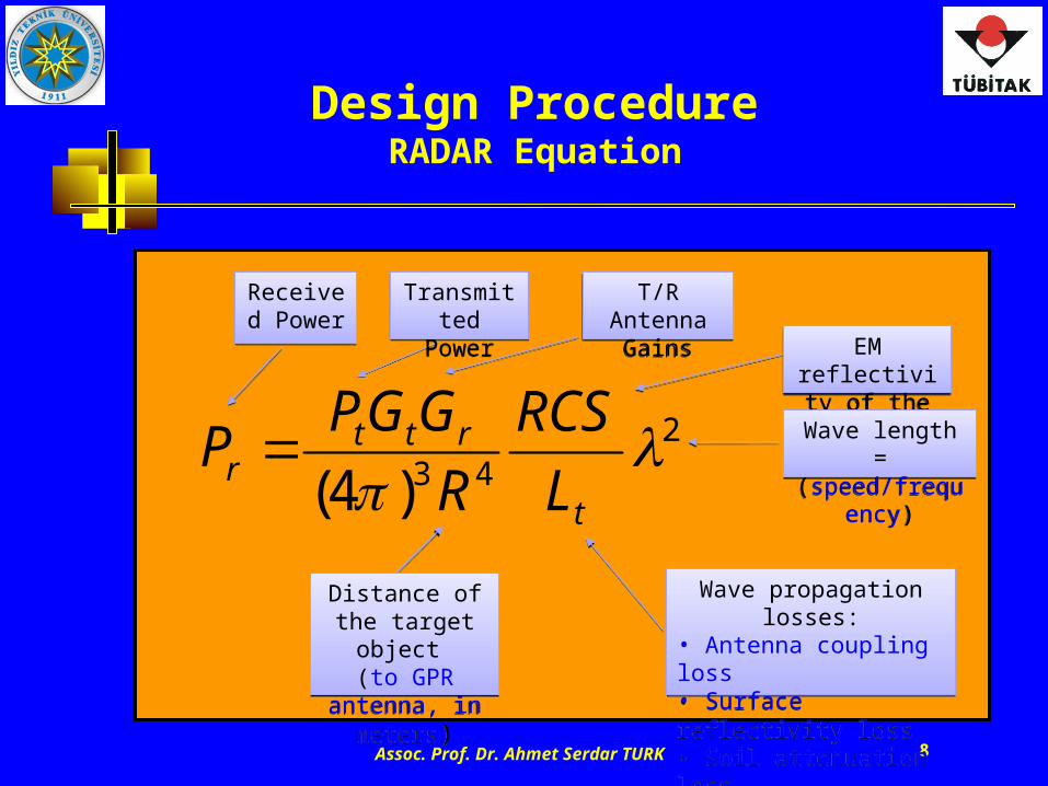
Design ProcedureRADAR Equation
243)4(
t
rttr L
RCS
R
GGPP
Transmitted Power
Transmitted Power
T/R Antenna Gains
T/R Antenna Gains
EM reflectivity of the target
EM reflectivity of the target
Received Power
Received Power
Wave length = (speed/frequency)
Wave length = (speed/frequency)
Wave propagation losses:• Antenna coupling loss• Surface reflectivity loss• Soil attenuation loss
Wave propagation losses:• Antenna coupling loss• Surface reflectivity loss• Soil attenuation loss
Distance of the target object
(to GPR antenna, in meters)
Distance of the target object
(to GPR antenna, in meters)
Assoc. Prof. Dr. Ahmet Serdar TURK 9
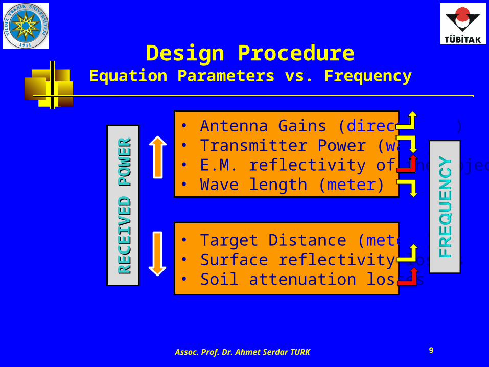
Design ProcedureEquation Parameters vs. Frequency
RE
CE
IVE
DR
EC
EIV
ED
PO
WE
RP
OW
ER
• Antenna Gains (directivity)• Transmitter Power (watt)• E.M. reflectivity of the object• Wave length (meter)
• Target Distance (meters)• Surface reflectivity losses• Soil attenuation losses
Assoc. Prof. Dr. Ahmet Serdar TURK 10
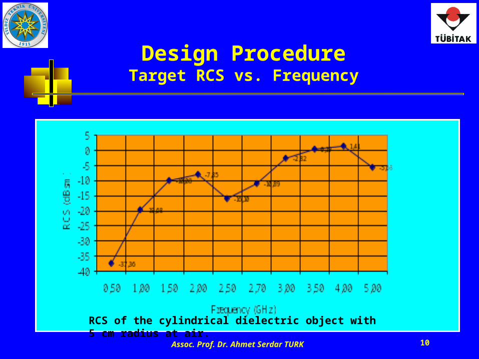
Design ProcedureTarget RCS vs. Frequency
RCS of the cylindrical dielectric object with 5 cm radius at air.
Assoc. Prof. Dr. Ahmet Serdar TURK 11
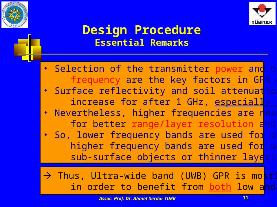
Design ProcedureEssential Remarks
• Selection of the transmitter power and operating frequency are the key factors in GPR design.• Surface reflectivity and soil attenuation losses highly increase for after 1 GHz, especially for wet soils.• Nevertheless, higher frequencies are needed to obtain for better range/layer resolution and radar echo.• So, lower frequency bands are used for deeper analysis, higher frequency bands are used for detection of smaller sub-surface objects or thinner layers located at shallow.
Thus, Ultra-wide band (UWB) GPR is mostly preferred in order to benefit from both low and high frequencies!
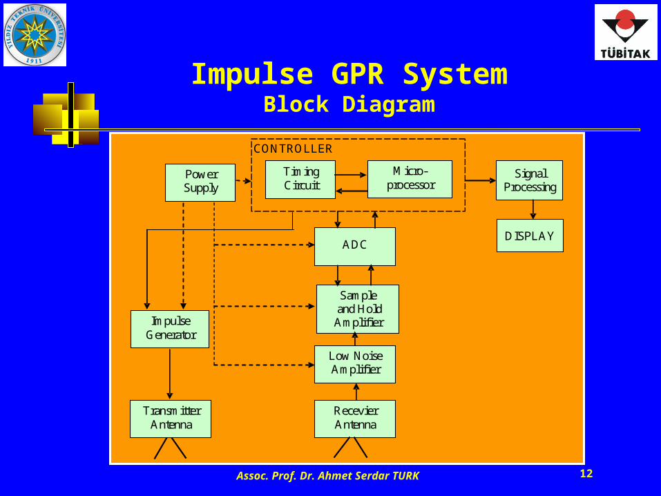
Assoc. Prof. Dr. Ahmet Serdar TURK 12
Impulse GPR SystemBlock Diagram
Timing Circuit
Impulse Generator
ADC
Sample and Hold Amplifier
Recevier Antenna
DISPLAY
Low Noise Amplifier
Power Supply
Signal Processing
CONTROLLER
Transmitter Antenna
Micro-processor
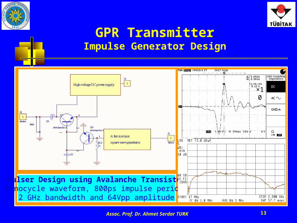
Assoc. Prof. Dr. Ahmet Serdar TURK 13
GPR TransmitterImpulse Generator Design
Pulser Design using Avalanche TransistorMonocycle waveform, 800ps impulse period,
2 GHz bandwidth and 64Vpp amplitude
×10
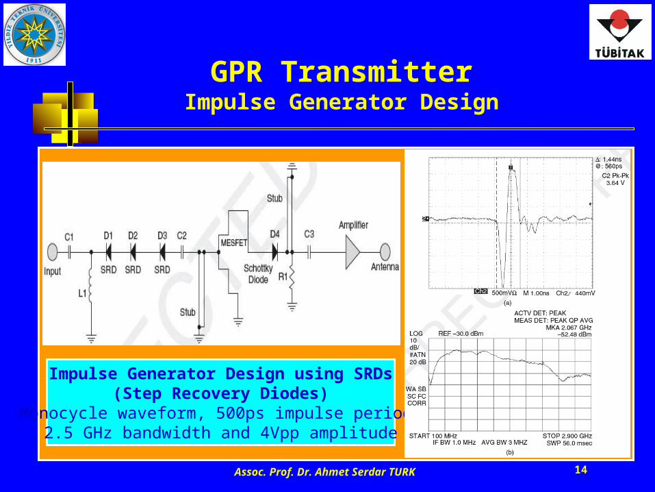
Assoc. Prof. Dr. Ahmet Serdar TURK 14
GPR TransmitterImpulse Generator Design
Impulse Generator Design using SRDs(Step Recovery Diodes)
Monocycle waveform, 500ps impulse period,2.5 GHz bandwidth and 4Vpp amplitude
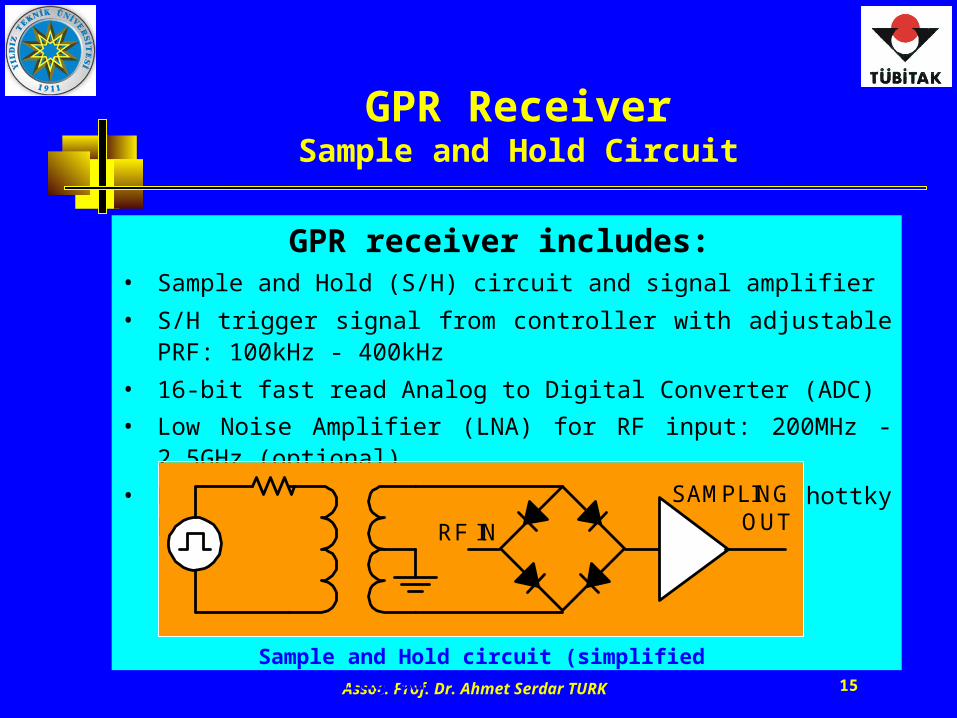
Assoc. Prof. Dr. Ahmet Serdar TURK 15
GPR receiver includes:
• Sample and Hold (S/H) circuit and signal amplifier
• S/H trigger signal from controller with adjustable PRF: 100kHz - 400kHz
• 16-bit fast read Analog to Digital Converter (ADC)
• Low Noise Amplifier (LNA) for RF input: 200MHz - 2.5GHz (optional)
• High speed switching using ultra fast Schottky Diode Bridge
RF IN
SAMPLINGOUT
GPR ReceiverSample and Hold Circuit
Sample and Hold circuit (simplified block diagram)
Assoc. Prof. Dr. Ahmet Serdar TURK 16
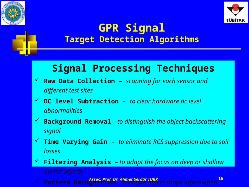
Signal Processing Techniques Raw Data Collection – scanning for each sensor and different test sites
DC level Subtraction – to clear hardware dc level abnormalities
Background Removal – to distinguish the object backscattering signal
Time Varying Gain – to eliminate RCS suppression due to soil losses
Filtering Analysis – to adapt the focus on deep or shallow buried objects
Pattern Recognition – to obtain object shape information
Data Integration – combining data received from multi sensors
Decision Algorithms – for buried object classification such as size, type..
GPR SignalTarget Detection Algorithms
Assoc. Prof. Dr. Ahmet Serdar TURK 17
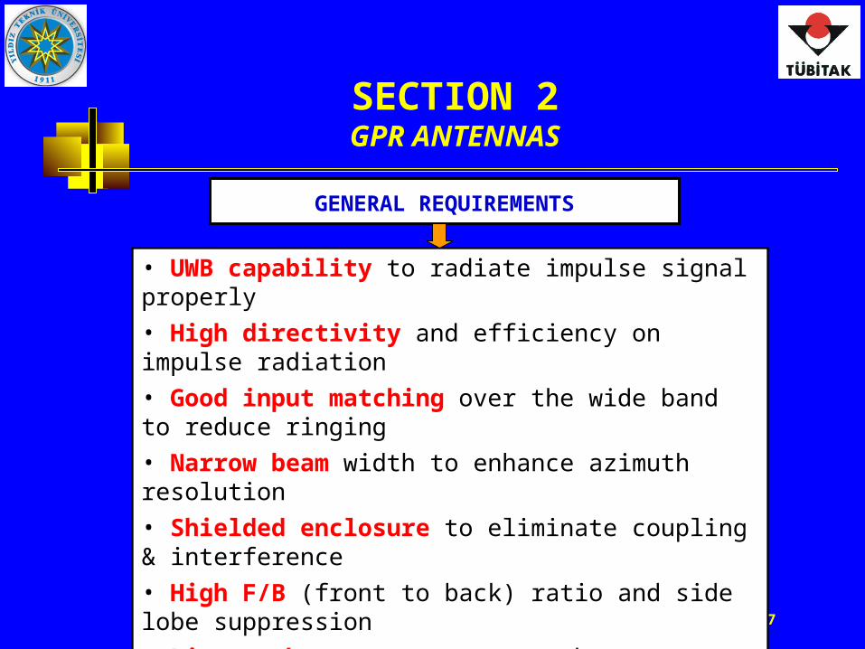
SECTION 2GPR ANTENNAS
• UWB capability to radiate impulse signal properly
• High directivity and efficiency on impulse radiation
• Good input matching over the wide band to reduce ringing
• Narrow beam width to enhance azimuth resolution
• Shielded enclosure to eliminate coupling & interference
• High F/B (front to back) ratio and side lobe suppression
• Linear phase response over the operational band
• Compatible polarization with respect to object alignment
• Physical suitability: Lightweight &small size for hand-held
• Multi-sensor adaptive for GPR operation with metal detector
GENERAL REQUIREMENTS
Assoc. Prof. Dr. Ahmet Serdar TURK 18
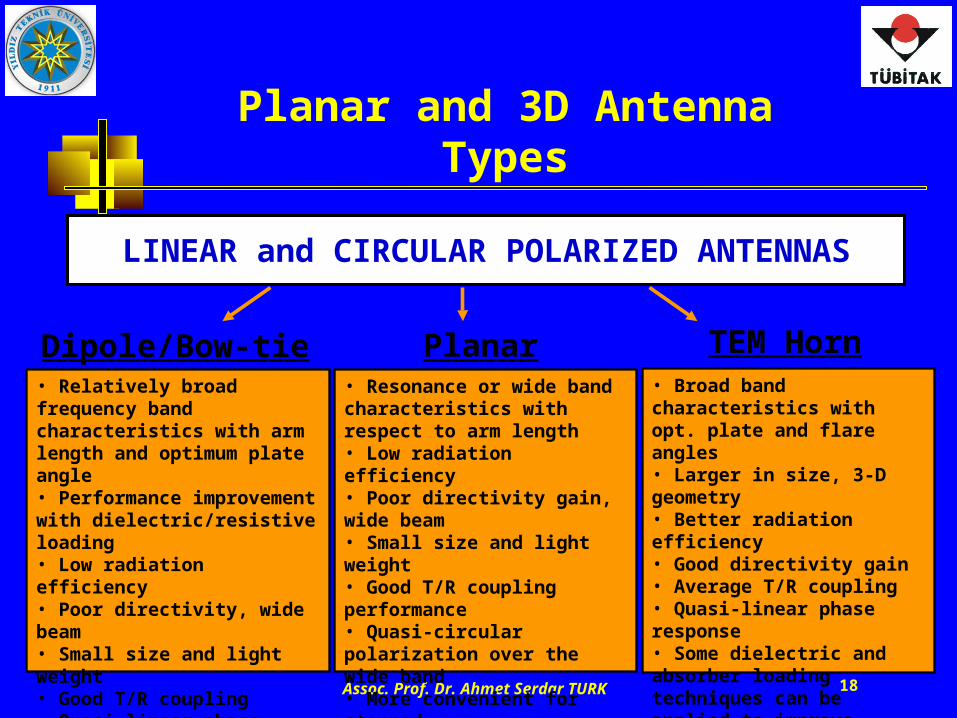
Planar and 3D Antenna Types
LINEAR and CIRCULAR POLARIZED ANTENNAS
Planar Spirals• Resonance or wide band characteristics with respect to arm length• Low radiation efficiency• Poor directivity gain, wide beam• Small size and light weight• Good T/R coupling performance• Quasi-circular polarization over the wide band• More convenient for stepped frequency applications
Dipole/Bow-tie• Relatively broad frequency band characteristics with arm length and optimum plate angle• Performance improvement with dielectric/resistive loading• Low radiation efficiency• Poor directivity, wide beam• Small size and light weight• Good T/R coupling • Quasi-linear phase response over the wide band• More convenient for hand-held impulse GPR applications
TEM Horn• Broad band characteristics with opt. plate and flare angles• Larger in size, 3-D geometry • Better radiation efficiency• Good directivity gain• Average T/R coupling • Quasi-linear phase response• Some dielectric and absorber loading techniques can be applied to improve antenna characteristics• More convenient for vehicle-mounted GPR applications
Assoc. Prof. Dr. Ahmet Serdar TURK 19
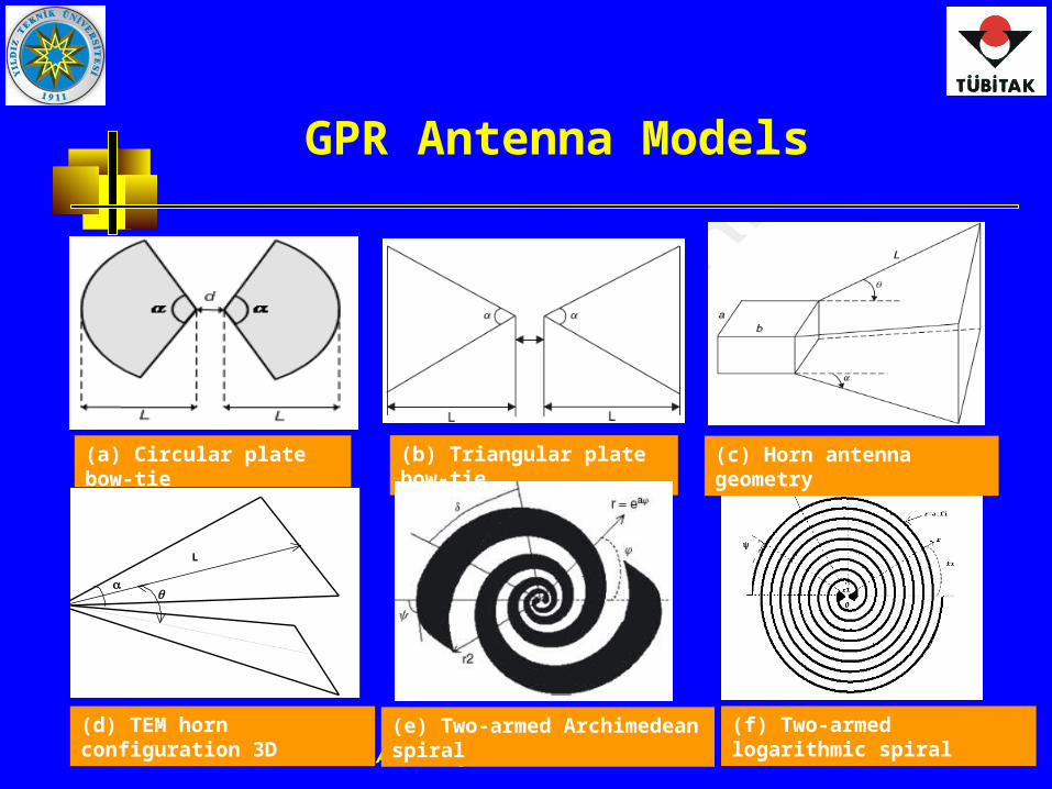
GPR Antenna Models
(a) Circular plate bow-tie (b) Triangular plate bow-tie
(f) Two-armed logarithmic spiral(e) Two-armed Archimedean spiral
L
(d) TEM horn configuration 3D
(c) Horn antenna geometry
Assoc. Prof. Dr. Ahmet Serdar TURK 20
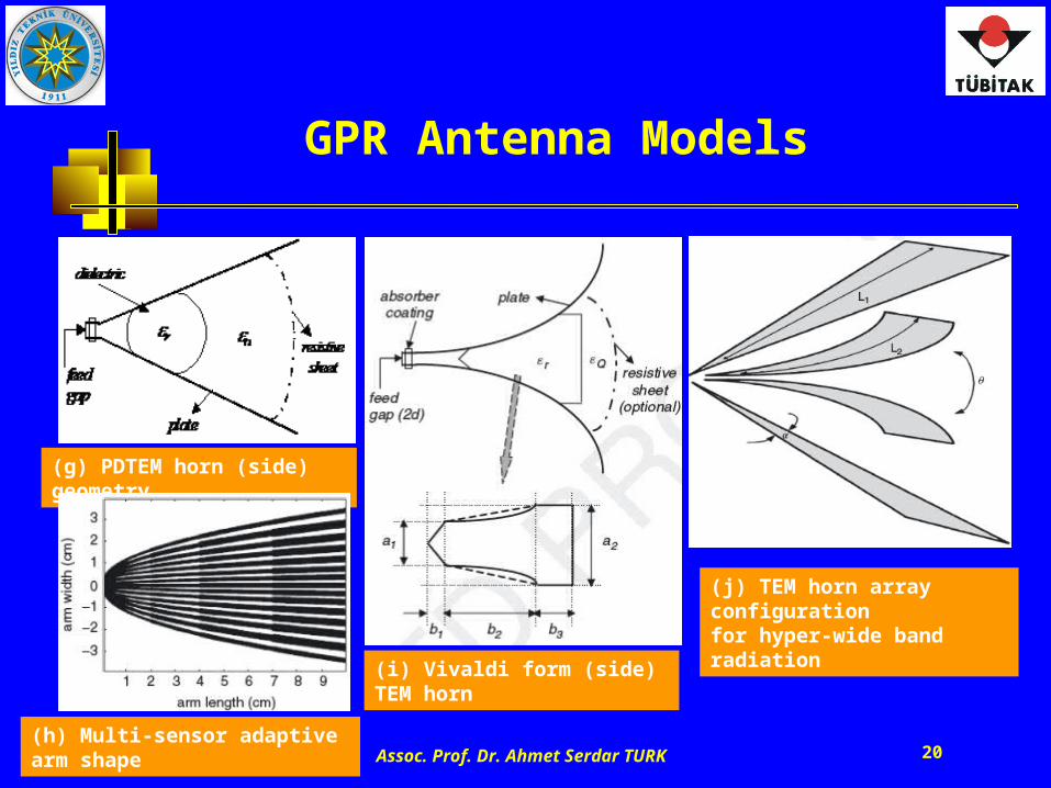
GPR Antenna Models
(h) Multi-sensor adaptive arm shape
(j) TEM horn array configurationfor hyper-wide band radiation
(g) PDTEM horn (side) geometry
(i) Vivaldi form (side) TEM horn
Assoc. Prof. Dr. Ahmet Serdar TURK 21
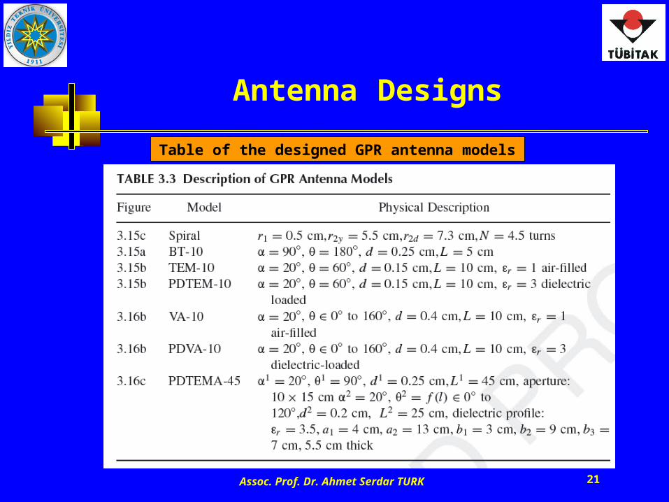
Antenna Designs
Table of the designed GPR antenna models
Assoc. Prof. Dr. Ahmet Serdar TURK 22
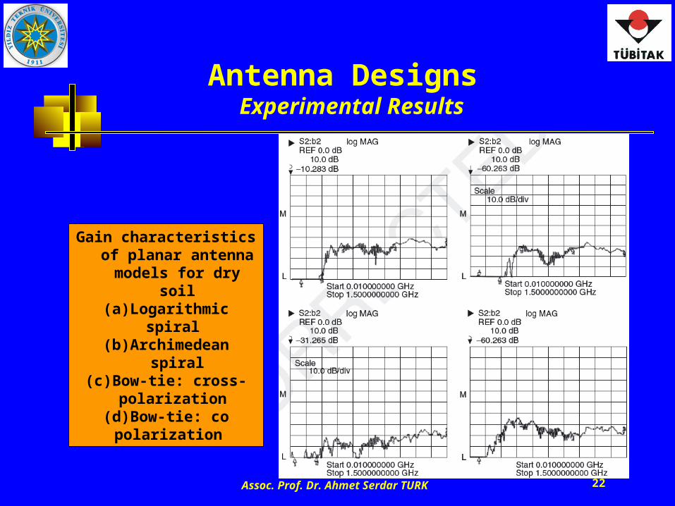
Antenna Designs Experimental Results
Gain characteristics of planar antenna models
for dry soil(a) Logarithmic spiral (b) Archimedean spiral
(c) Bow-tie: cross-polarization
(d) Bow-tie: co polarization
Assoc. Prof. Dr. Ahmet Serdar TURK 23
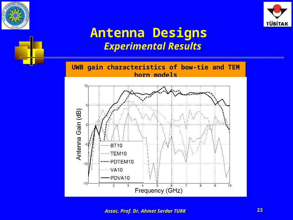
Antenna Designs Experimental Results
UWB gain characteristics of bow-tie and TEM horn models
Assoc. Prof. Dr. Ahmet Serdar TURK 24
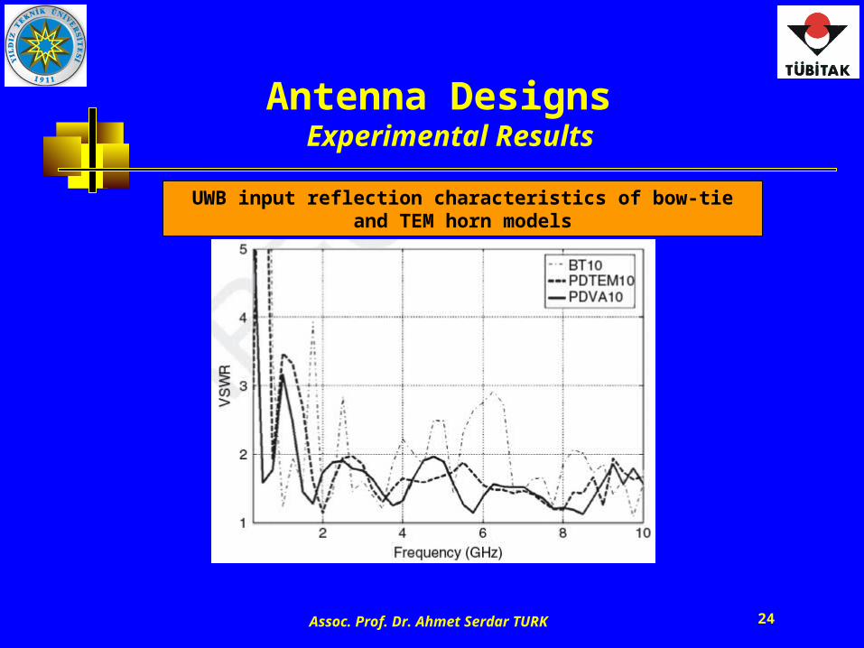
Antenna Designs Experimental Results
UWB input reflection characteristics of bow-tie and TEM horn models
Assoc. Prof. Dr. Ahmet Serdar TURK 25
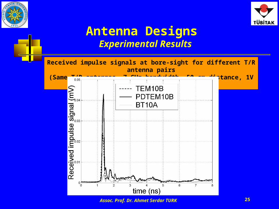
Antenna Designs Experimental Results
Received impulse signals at bore-sight for different T/R antenna pairs
(Same T/R antennas, 7 GHz bandwidth, 50 cm distance, 1V input pulse)
Assoc. Prof. Dr. Ahmet Serdar TURK 26
Antenna Designs Experimental Results
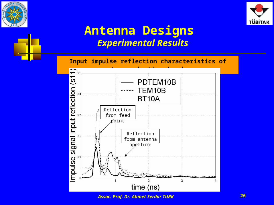
Input impulse reflection characteristics of antennas in time domain
Reflection from feed point
Reflection from antenna aperture
Assoc. Prof. Dr. Ahmet Serdar TURK 27
Antenna Designs Experimental Results
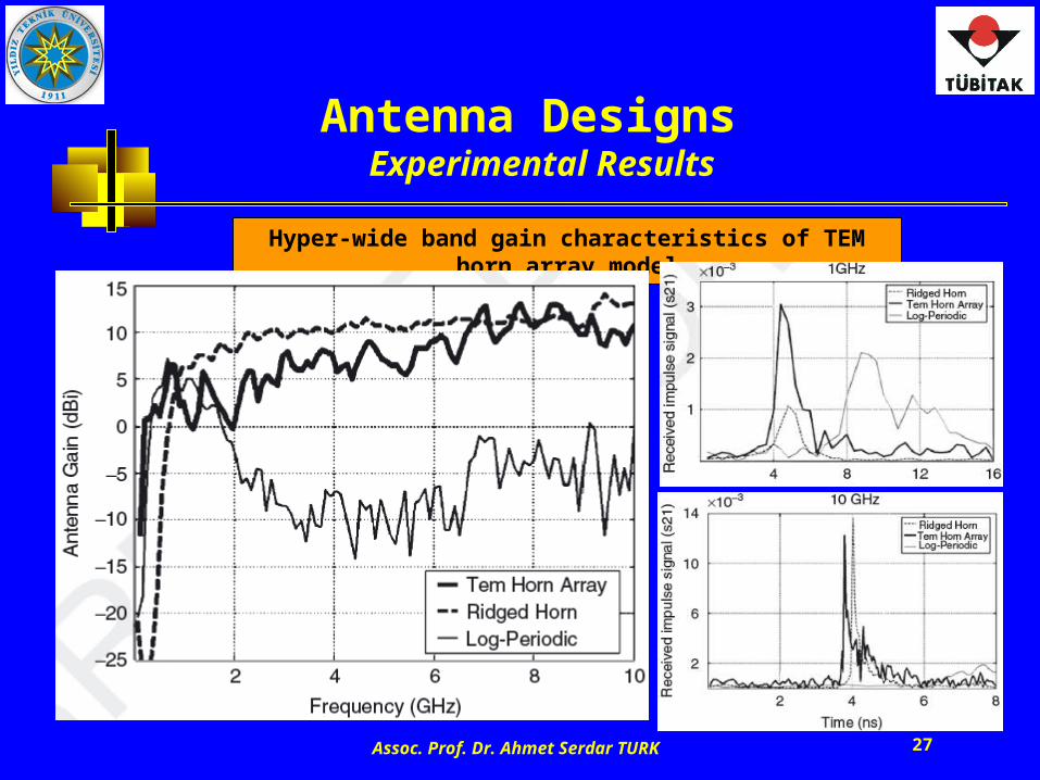
Hyper-wide band gain characteristics of TEM horn array model
Assoc. Prof. Dr. Ahmet Serdar TURK 28
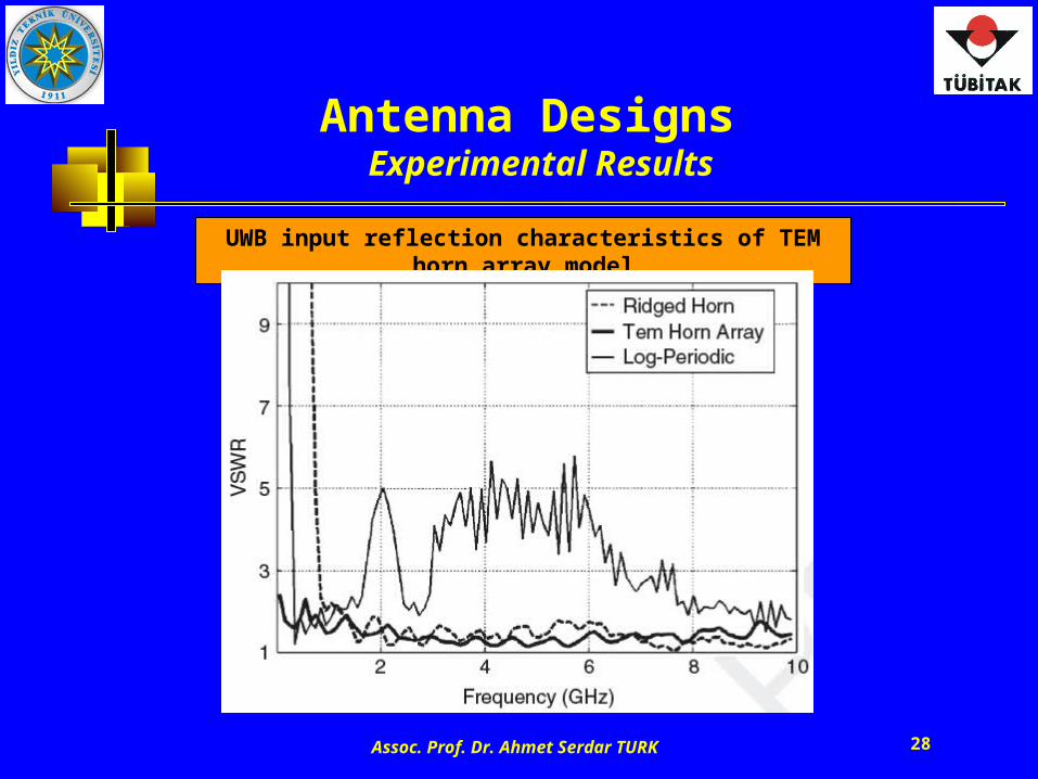
Antenna Designs Experimental Results
UWB input reflection characteristics of TEM horn array model
Assoc. Prof. Dr. Ahmet Serdar TURK 29
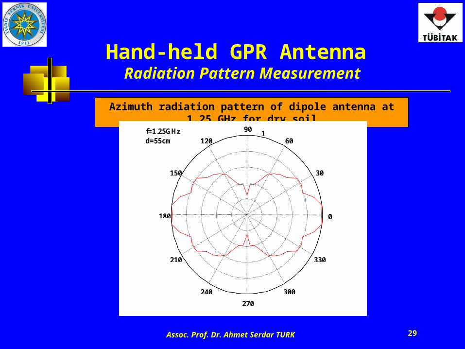
Hand-held GPR Antenna Radiation Pattern Measurement
Azimuth radiation pattern of dipole antenna at 1.25 GHz for dry soil
0.2
0.4
0.6
0.8
1
30
210
60
240
90
270
120
300
150
330
180 0
f=1.25GHz d=55cm
Assoc. Prof. Dr. Ahmet Serdar TURK 30
GPR HeadSimulation of Shielding Box Effects
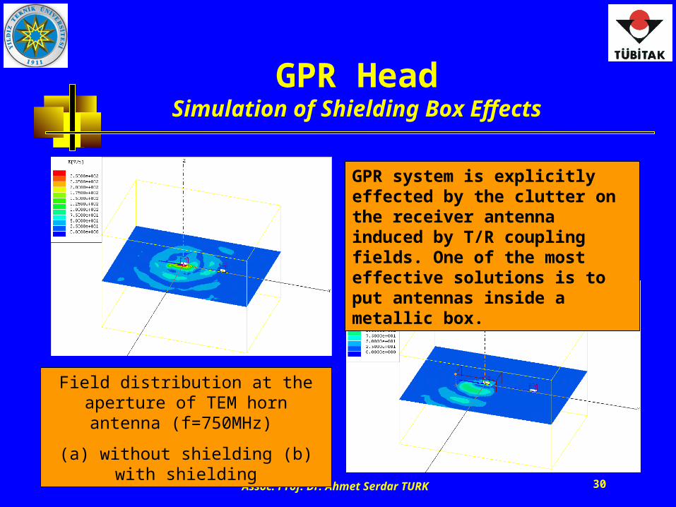
Field distribution at the aperture of TEM horn antenna (f=750MHz)
(a) without shielding (b) with shielding
GPR system is explicitly effected by the clutter on the receiver antenna induced by T/R coupling fields. One of the most effective solutions is to put antennas inside a metallic box.
Assoc. Prof. Dr. Ahmet Serdar TURK 31
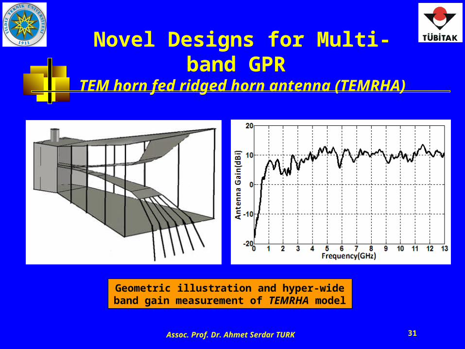
Novel Designs for Multi-band GPR TEM horn fed ridged horn antenna (TEMRHA)
Geometric illustration and hyper-wide band gain measurement of TEMRHA model
Assoc. Prof. Dr. Ahmet Serdar TURK 32
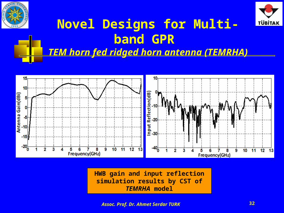
Novel Designs for Multi-band GPR TEM horn fed ridged horn antenna (TEMRHA)
HWB gain and input reflection simulation results by CST of TEMRHA model
Assoc. Prof. Dr. Ahmet Serdar TURK 33
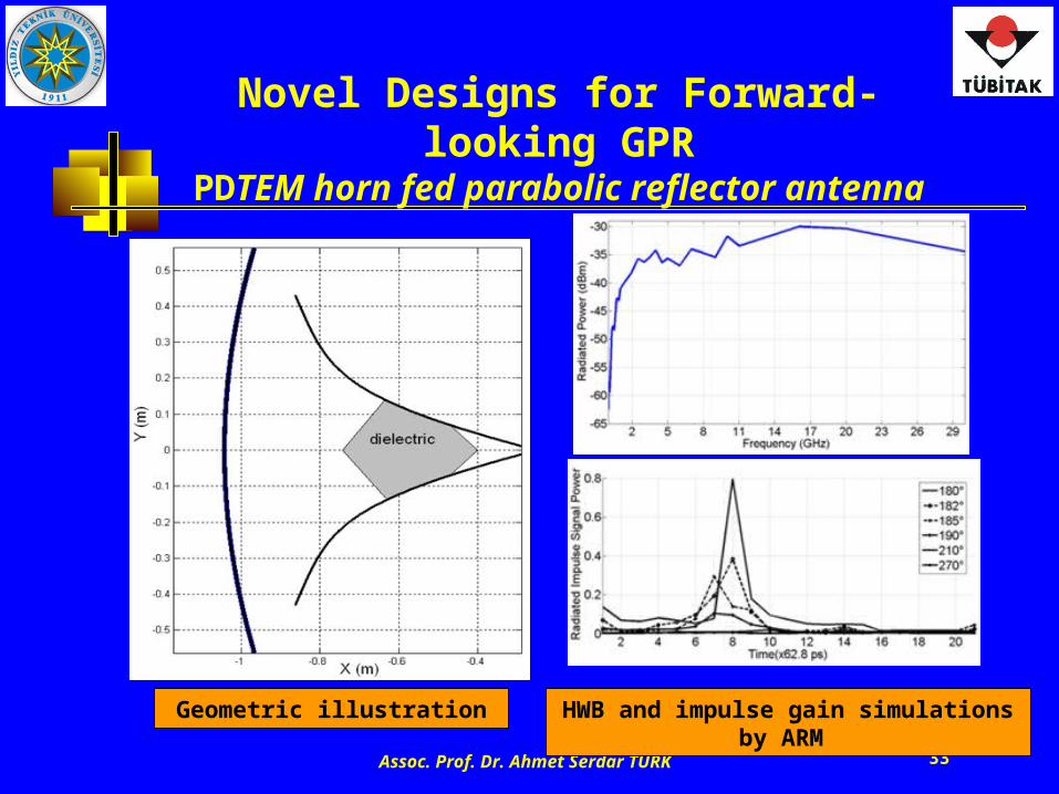
Novel Designs for Forward-looking GPRPDTEM horn fed parabolic reflector antenna
Geometric illustration HWB and impulse gain simulations by ARM
Assoc. Prof. Dr. Ahmet Serdar TURK 34
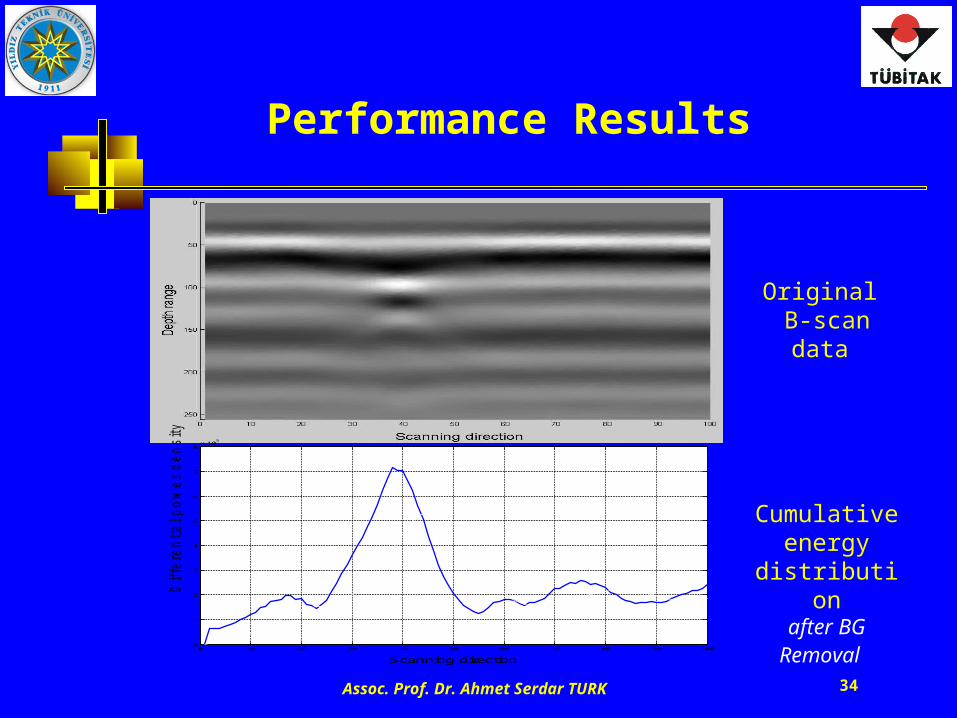
Performance Results
Original B-scan data
Cumulative energy
distributionafter BG Removal
0 10 20 30 40 50 60 70 80 90 1000
1
2
3
4
5
6
7
8x 10
5
Scanning direction
Diffe
rential pow
er d
ensity
Assoc. Prof. Dr. Ahmet Serdar TURK 35
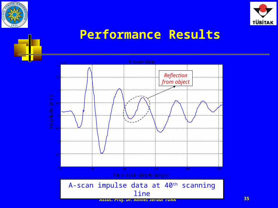
Performance Results
A-scan impulse data at 40th scanning line
0 50 100 150 200 250-2
-1.5
-1
-0.5
0
0.5
1
1.5
2x 10
4 A-scan data
Time scale (depth range)
Am
plit
ude (
mV
)
Reflection from object
Assoc. Prof. Dr. Ahmet Serdar TURK 36
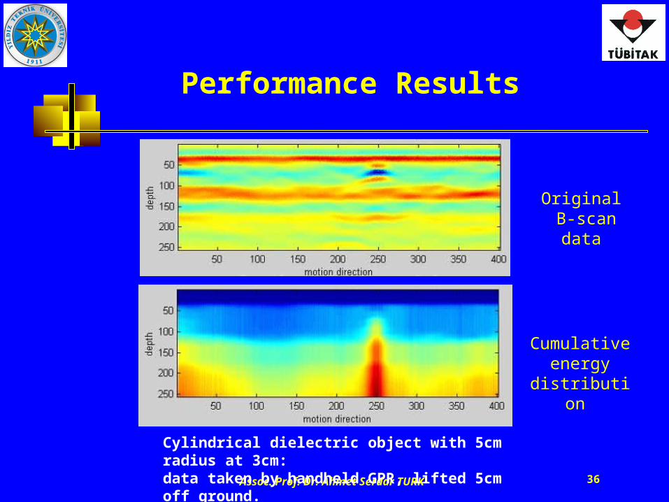
Performance Results
Cylindrical dielectric object with 5cm radius at 3cm: data taken by handheld GPR, lifted 5cm off ground.
Original B-scan data
Cumulative energy
distribution
Assoc. Prof. Dr. Ahmet Serdar TURK 37
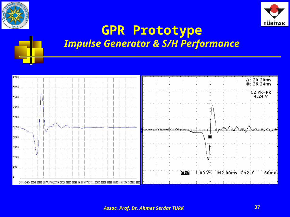
GPR PrototypeImpulse Generator & S/H Performance
Assoc. Prof. Dr. Ahmet Serdar TURK 38
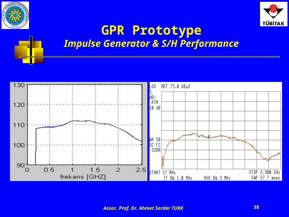
GPR PrototypeImpulse Generator & S/H Performance
Assoc. Prof. Dr. Ahmet Serdar TURK 39
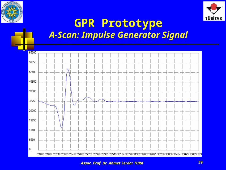
GPR PrototypeA-Scan: Impulse Generator Signal
Assoc. Prof. Dr. Ahmet Serdar TURK 40
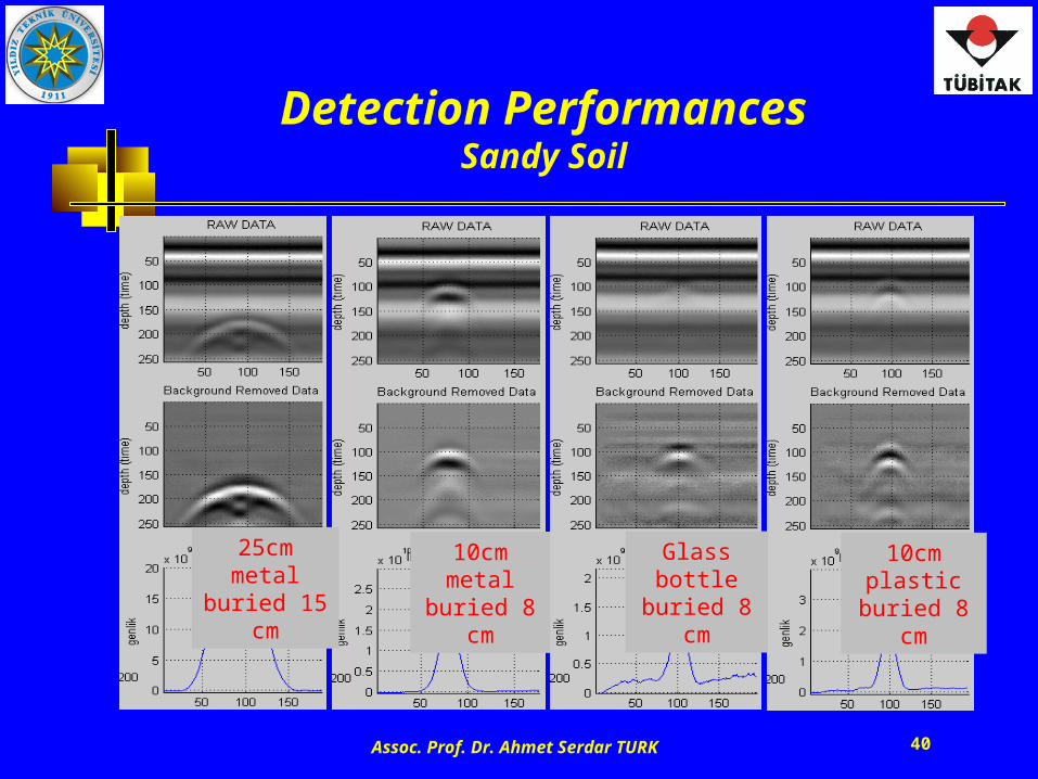
Detection PerformancesSandy Soil
25cm metal buried 15 cm
10cm metal buried 8 cm
Glass bottle buried 8 cm
10cm plastic buried 8 cm
Assoc. Prof. Dr. Ahmet Serdar TURK 41
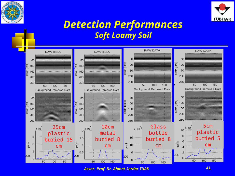
Detection PerformancesSoft Loamy Soil
25cm plastic buried 15 cm
10cm metal buried 8 cm
Glass bottle buried 8 cm
5cm plastic buried 5 cm
Assoc. Prof. Dr. Ahmet Serdar TURK 42
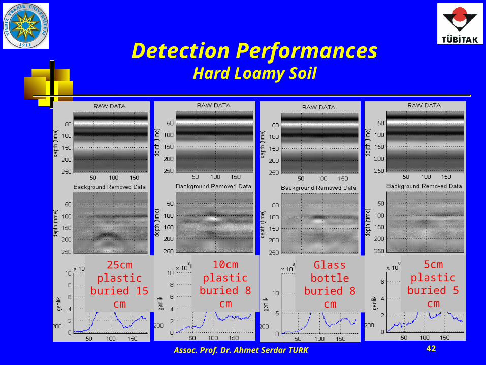
Detection PerformancesHard Loamy Soil
25cm plastic buried 15 cm
10cm plastic buried 8 cm
Glass bottle buried 8 cm
5cm plastic buried 5 cm
Assoc. Prof. Dr. Ahmet Serdar TURK 43
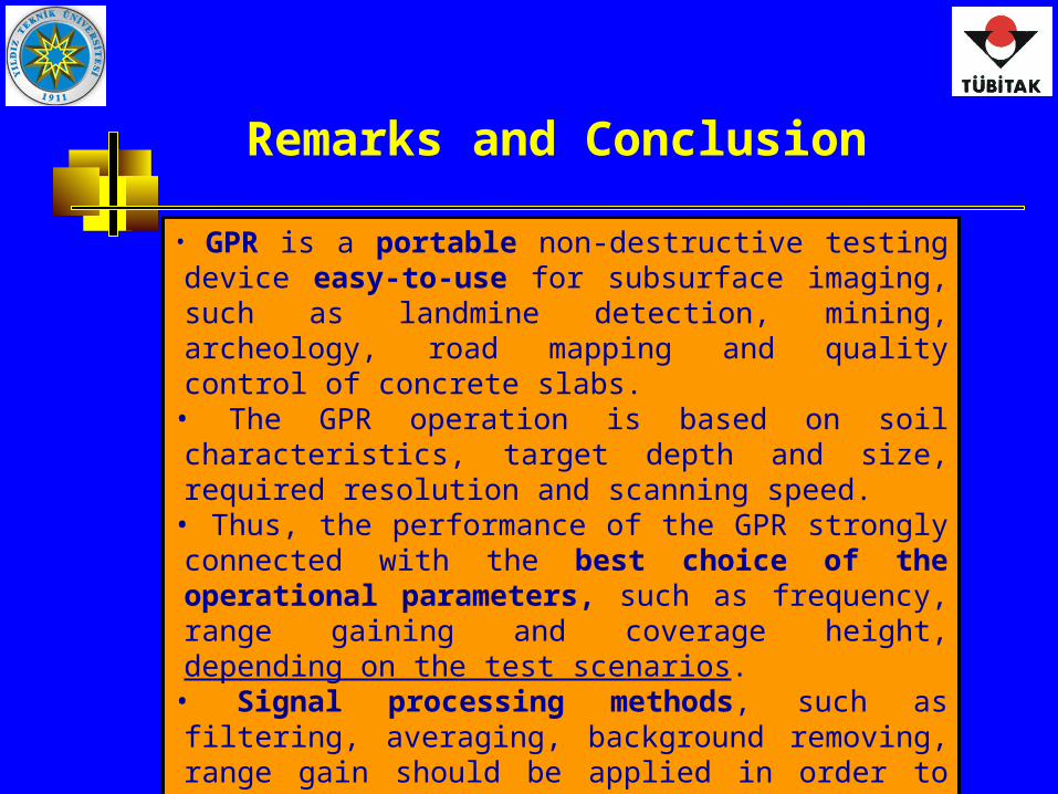
Remarks and Conclusion
• GPR is a portable non-destructive testing device easy-to-use for subsurface imaging, such as landmine detection, mining, archeology, road mapping and quality control of concrete slabs.
• The GPR operation is based on soil characteristics, target depth and size, required resolution and scanning speed.
• Thus, the performance of the GPR strongly connected with the best choice of the operational parameters, such as frequency, range gaining and coverage height, depending on the test scenarios.
• Signal processing methods, such as filtering, averaging, background removing, range gain should be applied in order to discriminate the targets from the received signal more visibly.
• Some experimental NDT and road survey results obtained by
using GSSI GeoRadar are presented in the following slides.
Assoc. Prof. Dr. Ahmet Serdar TURK 44
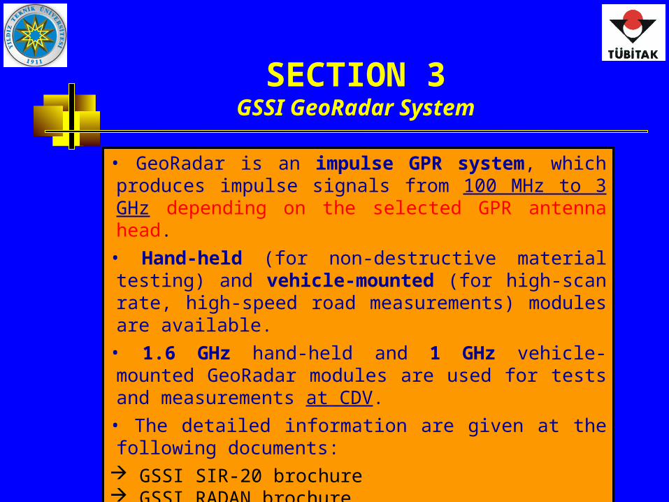
SECTION 3GSSI GeoRadar System
• GeoRadar is an impulse GPR system, which produces impulse signals from 100 MHz to 3 GHz depending on the selected GPR antenna head.
• Hand-held (for non-destructive material testing) and vehicle-mounted (for high-scan rate, high-speed road measurements) modules are available.
• 1.6 GHz hand-held and 1 GHz vehicle-mounted GeoRadar modules are used for tests and measurements at CDV.
• The detailed information are given at the following documents: GSSI SIR-20 brochure GSSI RADAN brochure GSSI Antenna brochure EPAM3-Portugal (sample application)
Assoc. Prof. Dr. Ahmet Serdar TURK 45
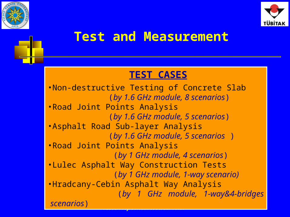
Test and Measurement
TEST CASES•Non-destructive Testing of Concrete Slab
(by 1.6 GHz module, 8 scenarios)•Road Joint Points Analysis
(by 1.6 GHz module, 5 scenarios)•Asphalt Road Sub-layer Analysis
(by 1.6 GHz module, 5 scenarios )•Road Joint Points Analysis
(by 1 GHz module, 4 scenarios)•Lulec Asphalt Way Construction Tests
(by 1 GHz module, 1-way scenario)•Hradcany-Cebin Asphalt Way Analysis
(by 1 GHz module, 1-way&4-bridges scenarios)
Assoc. Prof. Dr. Ahmet Serdar TURK 46
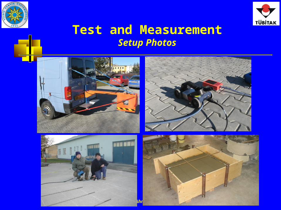
Test and MeasurementSetup Photos
Assoc. Prof. Dr. Ahmet Serdar TURK 47
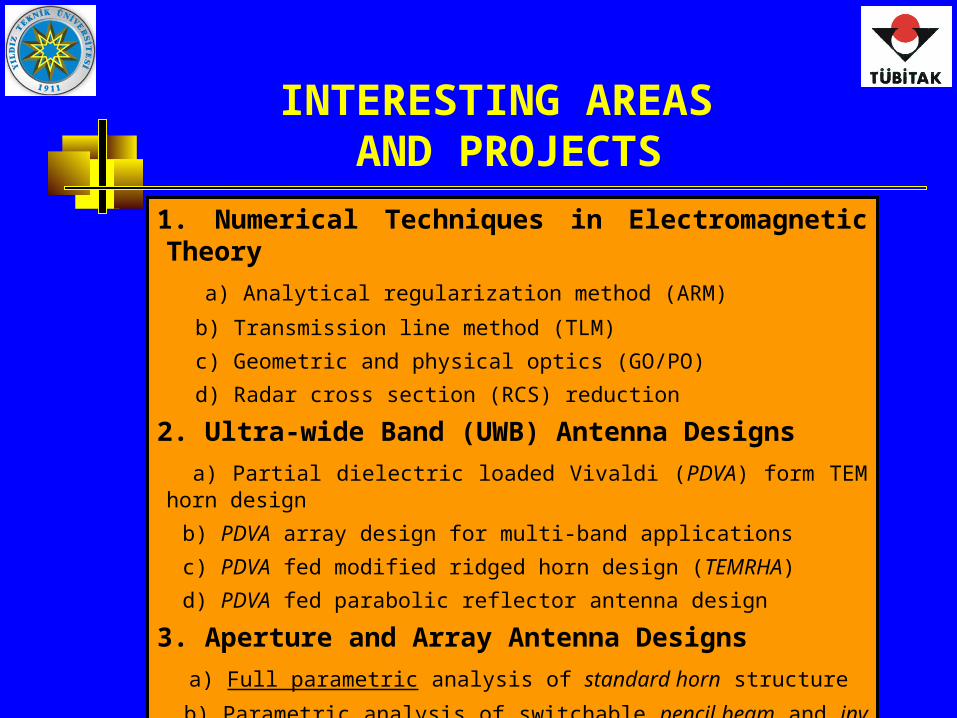
INTERESTING AREAS AND PROJECTS
1. Numerical Techniques in Electromagnetic Theory
a) Analytical regularization method (ARM)
b) Transmission line method (TLM)
c) Geometric and physical optics (GO/PO)
d) Radar cross section (RCS) reduction
2. Ultra-wide Band (UWB) Antenna Designs
a) Partial dielectric loaded Vivaldi (PDVA) form TEM horn design
b) PDVA array design for multi-band applications
c) PDVA fed modified ridged horn design (TEMRHA)
d) PDVA fed parabolic reflector antenna design
3. Aperture and Array Antenna Designs
a) Full parametric analysis of standard horn structure
b) Parametric analysis of switchable pencil beam and inv cosec2 reflector
c) 2D parametric analysis of coupling effects of horn and slot arrays
Assoc. Prof. Dr. Ahmet Serdar TURK 48
INTERESTING AREAS AND PROJECTS
4. UWB Ground-penetrating Impulse Radar (GPR) Design
a) UWB antennas
b) RF units (impulse generator and receiver)
c) Hand-held multi-sensor system for landmine detection
d) Through-wall imaging (TWI)
e) Forward-looking GPR, array and SAR applications
5. HF, Microwave and Millimeter wave Radar Systems
a) Over the horizon surface wave (HF) radar -for long range coastal surveillance
b) Active microwave radar for air and coastal surveillance
c) Active millimeter wave radar for short range high resolution target detection
d) Passive millimeter wave radar for short range surveillance
e) Millimeter wave SAR for UAV (unmanned air vehicle)
f) Analysis of clutter effects of wind turbines on microwave radars