Assessment of the Underground Distribution System of … of the Underground Distribution System of...
174
Assessment of the Underground Distribution System of the Potomac Electric Power Company Final Report December 7, 2001 Formal Case No. 991 Investigation into Explosions Occurring in or Around the Underground Distribution System of the Potomac Electric Power Company Prepared by Stone & Webster Consultants For the Public Service Commission of the District of Columbia
Transcript of Assessment of the Underground Distribution System of … of the Underground Distribution System of...

Assessment of the Underground Distribution System
of the Potomac Electric Power Company
Final Report
December 7, 2001
Formal Case No. 991Investigation into Explosions Occurring in or Around the Underground
Distribution System of the Potomac Electric Power Company
Prepared by Stone & Webster ConsultantsFor the Public Service Commission of the District of Columbia

Stone & Webster Consultants Pepco Assessment for DCPSC
2
Table of Contents
1.0 EXECUTIVE SUMMARY .................................................................................................................................. 5
1.1 PROJECT OBJECTIVE AND SCOPE ........................................................................................................................ 51.2 ASSESSMENT APPROACH .................................................................................................................................... 51.3 SUMMARY OF FINDINGS AND RECOMMENDATIONS ............................................................................................ 61.4 INTEGRITY OF PEPCO’S UNDERGROUND SYSTEM ............................................................................................... 71.5 ANALYSIS OF REPORTS AND FILINGS PREPARED BY PEPCO AND ITS CONSULTANTS........................................... 71.6 ANALYSIS OF REPORTS AND FILINGS PREPARED BY OTHER PARTIES ................................................................. 9
2.0 BACKGROUND ................................................................................................................................................. 10
2.1 INTRODUCTION ................................................................................................................................................. 102.2 APPROACH........................................................................................................................................................ 102.3 RADIAL AND NETWORK UNDERGROUND ELECTRICAL SYSTEMS...................................................................... 122.4 CAUSES OF MANHOLE INCIDENTS..................................................................................................................... 152.5 HISTORY OF MANHOLE INCIDENTS ................................................................................................................... 172.6 OTHER STUDIES RELATING TO MANHOLE INCIDENTS....................................................................................... 192.7 PILC SPLICE FAILURE MODES.......................................................................................................................... 20
3.0 FINDINGS AND RECOMMENDATIONS...................................................................................................... 22
3.1 NETWORK SYSTEM MODELING......................................................................................................................... 223.2 TECHNOLOGY ENHANCEMENTS ........................................................................................................................ 233.3 GEORGETOWN PROJECT.................................................................................................................................... 243.4 QUALITY ASSURANCE MEASURES .................................................................................................................... 253.5 STAFFING AND SUPPORT NEEDS ....................................................................................................................... 263.6 MANHOLE INSPECTIONS, REPAIRS, AND REPORTING PROGRAM ....................................................................... 26
4.0 FACILITIES INSPECTION.............................................................................................................................. 28
4.1 INTRODUCTION ................................................................................................................................................. 284.2 MANHOLE INSPECTION CRITERIA ..................................................................................................................... 284.3 REVIEW OF MANHOLES WITHIN GEORGETOWN ................................................................................................ 314.4 REVIEW OF MANHOLES OUTSIDE GEORGETOWN.............................................................................................. 414.5 REVIEW OF TRANSFORMER AND SWITCH VAULTS ............................................................................................ 474.6 REVIEW OF SUBSTATIONS................................................................................................................................. 50
5.0 INTEGRITY OF PEPCO’S UNDERGROUND DISTRIBUTION SYSTEM............................................... 53
5.1 INTRODUCTION ................................................................................................................................................. 535.2 SUMMARY......................................................................................................................................................... 535.3 DETAILS OF THE ASSESSMENT .......................................................................................................................... 54
6.0 POWER FLOW MODELING........................................................................................................................... 61
6.1 INTRODUCTION ................................................................................................................................................. 616.2 DEVELOPMENT OF ANALYTICAL MODELING .................................................................................................... 616.3 ANALYTICAL MODELING OF SECONDARY NETWORKS ..................................................................................... 626.4 PEPCO SECONDARY NETWORK ANALYTICAL MODELING................................................................................. 62
7.0 RECENT TECHNOLOGIES ............................................................................................................................ 65
7.1 FAULT CURRENT-LIMITING DEVICES................................................................................................................ 657.2 ADVANTAGES OF FAULT-LIMITING DEVICES IN PEPCO'S SYSTEM .................................................................... 677.3 FAULT LOCATION TIME IN NETWORK SYSTEMS ............................................................................................... 687.4 ISOLATED SPOT NETWORKS.............................................................................................................................. 687.5 RECOMMENDATIONS ON NEW TECHNOLOGIES ................................................................................................. 69

Stone & Webster Consultants Pepco Assessment for DCPSC
3
Table of Contents (continued)
APPENDIX A ANALYSIS OF REPORTS & FILINGS PREPARED BY PEPCO & ITS CONSULTANTS......71
REVIEW OF Final Report on Manhole Event Tests for Pepco at Lenox EPRI Final Report WO-049296 ......72
REVIEW OF Report of Potomac Electric Power Company in Response to Commission Order No. 12036 ..79
REVIEW OF Georgetown Area Low-Voltage Network ABB Final Report Dated January 15, 2001 ..............89
REVIEWS OF Georgetown Area Network System Evaluation ABB Final Report May 21, 2001 And 4 kVSystem Load Flow and Reliability Analysis Final Report March 9, 2001 .....................................................118
Pepco’s Original and Revised Priority Definitions - Manhole Reliability Inspection.....................................122
APPENDIX B ANALYSIS OF REPORTS & FILINGS PREPARED BY OTHER PARTIES ..........................124
REVIEW OF Downes Associates Report Dated October 31, 2000 ...............................................................125
REVIEW OF Office of the Peoples Council’s Comments in Response to Order No. 12036 .........................133
APPENDIX C STONE & WEBSTER’S DATA REQUESTS TO PEPCO............................................................136
APPENDIX D STONE & WEBSTER’S MONTHLY REPORTS TO THE DCPSC ...........................................146
APPENDIX E STONE & WEBSTER’S DETAILED WORK PLAN AND SCHEDULE ...................................169
APPENDIX F REFERENCE MATERIALS............................................................................................................174

Stone & Webster Consultants Pepco Assessment for DCPSC
4
List of Figures
Figure 1 Simplified Radial Primary Distribution System ............................................................. 12
Figure 2 Simplified Low-Voltage Secondary Network System.................................................... 14
Figure 3 Stone & Webster Inspection Locations of Pepco’s Underground Distribution Systemwithin Washington DC.......................................................................................................... 30
Figure 4 Crowded Manhole within Georgetown with Primary Cables, Secondary Cables, andTraffic Signal or Street Light Cable ...................................................................................... 33
Figure 5 Manhole (Handhole) in Georgetown Crowded with Secondary Cables......................... 34
Figure 6 Crowded Manhole in Georgetown with Primary and Secondary Cables in Very CloseProximity............................................................................................................................... 35
Figure 7 Hot (290o F) Secondary Splice Located During Field Inspection................................... 36
Figure 8 Overheated Secondary Cable Removed from Georgetown after a Manhole Incident ... 37
Figure 9 Terracotta Ducts with Primary and Secondary Cables within a Duct Bank................... 38
Figure 10 Ductbank with PVC Ducts and Two Sets of Secondary Cables in One Duct .............. 39
Figure 11 Debris Inside a Manhole With a Slotted Cover ............................................................ 40
Figure 12 Tap Hole Showing Load Break Elbow Connectors...................................................... 41
Figure 13 Secondary Bus Hole Showing Quality Workmanship.................................................. 42
Figure 14 Crowded Adams Morgan Manhole............................................................................... 43
Figure 15 Staggered Secondary Bus Design ................................................................................. 44
Figure 16 Imploded Primary PILC Y-Splice ................................................................................ 45
Figure 17 Primary Cables with Small Radius Bend and Missing Porcelain in the Saddle ........... 46
Figure 18 Single Phase Transformer Using Elbow Primary Connector ....................................... 47
Figure 19 New Transformer Vault with Neatly Arranged Secondary Cables .............................. 48
Figure 20 Flooded Transformer Vault with Debris....................................................................... 49
Figure 21 69 kV Transmission Cable Leaking Dielectric Fluid ................................................... 50
Figure 22 Primary Feeders in Substation Showing Good Workmanship ..................................... 51
Figure 23 Primary Feeders in Substation with Leaking Splice..................................................... 52
Figure 24 Georgetown East Network Load Flow Results from ABB Report............................... 63
Figure 25 Comparison of Waveform of Fault Current from Substation with and without aCurrent-Limiting Device at the Station ................................................................................. 66

Stone & Webster Consultants Pepco Assessment for DCPSC
5
1.0 EXECUTIVE SUMMARY
1.1 Project Objective and ScopeThe objective of this assignment was to perform an independent assessment of Potomac ElectricPower Company’s (Pepco) underground electric distribution facilities in light of a series ofmanhole explosions and fires that have occurred in the District of Columbia (DC) over the pastseveral years. In performing this assessment, Stone & Webster Consultants (Stone & Webster)was also required to review and evaluate the filings and studies submitted by all parties toFormal Case No. 991, opened by the Public Service Commission of the District of Columbia(DCPSC) on March 6, 2000, to investigate the causes and remedies for the manhole explosionsand fires in Pepco's underground electric distribution system.
1.2 Assessment ApproachStone & Webster conducted its assessment during the period of May 2001 through November2001, which involved six consultants. In addition, the DCPSC Project Administrator attendedseveral of Stone & Webster’s team meetings with Pepco officials, and visited Stone & Webster’sfield investigation teams during inspections of Pepco’s underground electric distributionfacilities. More specifically, Stone & Webster’s assessment included the following elements:
- field inspections of 41 manholes, 15 transformer vaults, 3 switch vaults, and 5 substationsin Pepco’s underground electric distribution system in DC,
- review and analysis of Formal Case 991 studies and filings submitted by Pepco and itsconsultants, ABB Power T&D, Inc. (ABB) and the Electric Power Research Institute(EPRI); the Office of the People’s Counsel of the District of Columbia (OPC) and itsconsultant, Downes Associates; and all other parties to Formal Case No. 991,
- submission of data requests to Pepco and subsequent review and analysis of responses,
- review of Pepco’s engineering design, construction, materials, operation, maintenance,and inspection practices,
- individual interviews and team interviews with members of Pepco’s power deliveryorganization management and technical personnel,
- a team interview with representatives of ABB at their offices in Raleigh, NC to discussthe results of their studies performed for Pepco,
- attendance at EPRI’s manhole event workshop held in DC, and discussion of theirmanhole tests performed for Pepco, and
- attendance at hearings held by the DCPSC, and review of hearing transcripts.

Stone & Webster Consultants Pepco Assessment for DCPSC
6
1.3 Summary of Findings and RecommendationsThe following summarizes our major findings and recommendations:
- based on our review and examination of ABB’s Georgetown area network systemevaluation, and other elements of our assessment, it is our professional opinion thatoverloading is a primary factor in cable and splice failures, which may ultimately lead tomanhole smoking, fires and explosions, and we recommend that Pepco’s analyticalelectrical modeling of the network system to determine overloaded portions of thenetwork be expedited from its four-year plan to a targeted completion date of the spring,2003;
- based on our physical inspections and observations, we recommend that the networksserving the Adams Morgan area be given high priority in terms of the modeling effortbecause it shows significant overcrowding resulting from load growth;
- based on the high primary fault current levels on Pepco’s system, and reported experienceof Tampa Electric Company, we recommend Pepco perform a technical feasibility studyof the application and installation of high speed, electronically controlled fuses and othercurrent-limiting devices designed to limit fault currents by fast fault clearing; we believesuch a study should be completed in nine to twelve months;
- Pepco should continue its trial installation of a remote monitoring system for networktransformers and protectors, and we note that Consolidated Edison of NY employs realtime remote monitoring on all 24,000 of its network transformers and protectors;
- evaluate the applicability of new technologies such as the above-ground meter and real-time fault location schemes that allow crews to quickly locate faulted cables under thestreet;
- consider alternate protection schemes for isolated spot networks;
- the Georgetown Project will separate primary from secondary cable circuits, reducetemperature buildup and improve heat dissipation, reduce the probability of a secondarycable failure propagating into a primary circuit failure (and vice versa), and make repairseasier; we recommend that Pepco capture all as-built Georgetown Project constructionrecords in a form suitable for input into its GIS database;
- Pepco should perform network system modeling of the Georgetown Project design inorder to evaluate the adequacy of the design before it is constructed;
- although our field inspections have noted good workmanship in manholes, primary splicefailures have been involved in a number of manhole incidents, and we recommend asplicing /repair log be kept containing dates of installation, crew members performing thework, materials used, and other information deemed suitable for GIS database entry;
- based on the anticipated Georgetown construction activity, the manhole inspections andrepairs program, our suggested expediting of the modeling of electrical networks, and the30% decrease in underground and conduit staffing levels which occurred over the pastdecade, we recommend Pepco conduct a work force staffing analysis to assess the

Stone & Webster Consultants Pepco Assessment for DCPSC
7
adequacy of its work force to meet these demands; this should be completed within threeto four months;
- based on our review and examination of EPRI’s manhole cover test results and theperformance of recently installed slotted manhole covers, we recommend that Pepcocontinue its ongoing installation and evaluation of slotted manhole covers;
- we recommend modifications to the manhole repair prioritization schedule to assuretimely repairs, and additions to the information contained on the manhole inspectionreports so as to develop a more comprehensive database. (A revised repair prioritizationschedule has been adopted by Pepco and is included in Appendix A.5.)
1.4 Integrity of Pepco’s Underground SystemIn addition to the recommendations for improvements summarized above, our review examinedthe overall integrity of Pepco’s underground system. That review found the following:
- the integrity of major components of the underground system, namely distributionsubstations, network systems, the 13 kV and 4 kV radial systems are acceptable with theexception of sections of the Georgetown area which are characterized by overcrowdedfacilities due to load growth beyond the design criteria of the affected undergroundfacilities, and overloading of circuits during both normal and single contingency (e.g.,loss of one primary) conditions;
- the distribution substations employ designs, materials, and protection practices that areequal to or better than those of other metropolitan utilities;
- the distribution substations are designed to provide a high level of reliability and servicecontinuity;
- the 47 low voltage network systems generally located in commercial areas are welldesigned, protected in accordance with or better than industry practice, use equipmentand materials that are standard in the industry, and evidence good workmanship inmanholes, transformer vaults, and bus holes;
- the 4 kV and 13 kV radial systems deployed mainly in residential areas are consistentwith utility industry practices, and the 13 kV system uses the latest materials available inthe industry.
However, our assessment does not include an examination of actual loading on facilities andequipment during normal and/or single contingency conditions because Pepco has not yetcompleted development of the load flow models needed to perform this analysis.
1.5 Analysis of Reports and Filings Prepared by Pepco and its ConsultantsThe following summarizes our review and comments (see Appendix A) regarding reports andfilings by Pepco and its consultants.
• With regard to ABB’s Georgetown Area Network System Evaluation (also referred to as themodeling study), the results of the load flow analysis show some Georgetown networks are

Stone & Webster Consultants Pepco Assessment for DCPSC
8
not able to handle peak load conditions without overloading secondary cables, even with allprimary feeders in service. Moreover, during a single contingency (e.g., loss of one primaryfeeder) many secondary cables are severely overloaded, as well as some networktransformers, and in some cases the remaining primary feeders. This is the most significantfinding of the ABB analysis because secondary cables have been implicated in a number ofmanhole incidents.
With regard to ABB's 4 kV system study, its results support Pepco’s decision to convert the 4 kVradial distribution system in the residential area of Georgetown (adjacent to the network system)to a 13 kV loop system, so as to be able to carry higher loads and enable quicker servicerestoration. Overall, the study found:
− The reliability indices (SAIDI, SAIFI) of the 4 kV radial distribution system inGeorgetown reflect substandard performance. The 5-year record of outage statisticsindicates significantly higher failure rates than experienced in new underground systems.
− Overloaded 4 kV cables under peak system load conditions.− A primary feeder with a voltage drop in excess of 4%.
• With regard to ABB's Final Report on the Georgetown Area Low-Voltage Network (alsoreferred to as the facilities study), the ABB report contained 14 recommendations for thelow-voltage network systems. If Pepco follows these recommendations, the performance ofthe low-voltage network systems will be improved. Our review proposes three additionalrecommendations:
- evaluate the applicability of high-voltage current-limiting devices such as used by TampaElectric to reduce the probability of a fault in a primary splice causing a manholeexplosion, and prevent the rupturing of transformer cable terminal and switchcompartments;
- evaluate the applicability of new technologies such as the above-ground meter and real-time fault location schemes that allow crews to quickly locate faulted cables under thestreet;
- consider alternate protection schemes for isolated spot networks (e.g., the circular closecharacteristic of microprocessor relays).
• With regard to EPRI's Final Report on Manhole Event Tests, we find:
- the study was carefully conducted using appropriate laboratory technique andinstrumentation;
- the study results are based on a reasonable reproduction of conditions observed in thefield;
- Pepco’s decision to install non-tethered slotted manhole covers is appropriate, given thatsuch equipment can reduce the severity of a manhole event.
It should be noted that a high current arc by itself can have sufficient energy to result in amanhole incident, that is, no combustible gases are necessary. As a result, mitigation methodsmay be different for primary versus secondary cable-caused incidents if for example primarycable splice failures result from arc energy while secondary cable faults result from combustion

Stone & Webster Consultants Pepco Assessment for DCPSC
9
of liberated gases. We note to date, no slotted manhole covers have lifted due to a manholeincident.
• With regard to Pepco’s response to Commission Order No. 12036, we find overall, Pepco isimplementing the recommendations made by ABB in the modification of standards that willbe used in rebuilding the Georgetown system. Specifically:
- Pepco is revising the ratings assigned to primary circuit cables installed in ductsthroughout DC, to take into account the heating effects of low-voltage cables in the sameduct bank, which will result in a more appropriate conservative design;
- Pepco will measure soil thermal resistivity which will be used for calculating cableampacity ratings (i.e. the amount of current a cable can carry without overheating);
- load flow models of the networks are being developed using the recently purchasedEasyPower software;
- Pepco’s installation of slotted manhole covers, based on EPRI test results, appears to be aprudent approach to reducing manhole cover displacements;
- the Georgetown modernization plan appears to be appropriately designed, will use EPRinsulated cable (instead of PILC), and should improve reliability and allow for systemcapacity enhancements to accommodate future load growth.
1.6 Analysis of Reports and Filings Prepared by Other PartiesThe following summarizes our review and comments (see Appendix B) regarding reports andfilings by the OPC and its consultants, and other parties.
• With regard to the Downes Associates Report Dated October 31, 2000 and filed by the OPCon November 3, 2000, we find:− the report contains several appropriate recommendations that Pepco has acted upon (e.g.,
conduct failure analysis, carry out manhole inspections, and reliability inspectionreporting);
− however, we disagree with Downes’ assertion that age is the primary causative factor andGIS the primary solution to failures in the underground system;
− instead, we believe loading is the most significant factor, and the most immediate need isfor electrical analytical modeling and load flow studies of the underground system,particularly the secondary networks.
• With regard to the OPC’s Comments filed on July 24, 2001, in Response to Order No. 12036,we find that:− although Downes’ discredits EPRI’s manhole cover tests, we disagree since we believe
that the tests were carefully conducted using appropriate laboratory technique andinstrumentation, and that the installation of non-tethered slotted covers can reduce theseverity of a manhole incident;
− although Pepco is only installing slotted covers in sidewalks and crosswalks, the impactof exposure to street debris will require monitoring.

Stone & Webster Consultants Pepco Assessment for DCPSC
10
2.0 BACKGROUND
2.1 IntroductionOn January 9, 2001, the Public Service Commission of the District of Columbia (DSPSC orCommission) issued a Request for Proposal (RFP) to perform an assessment of the undergrounddistribution system of the Potomac Electric Power Company (Pepco). The assessment is part ofFormal Case No. 991, opened by the DCPSC on March 6, 2000, dealing with the cause or causesof manhole explosions and fires in the District of Columbia. In its RFP the Commissionrequested
“an independent and comprehensive review and evaluation of the scope, methodology,results, conclusions, and recommendations of the assessments and studies carried out byPepco and its consultants, ABB Power T&D, Inc. (ABB) and the Electric PowerResearch Institute (EPRI), and a review of the filings of the Office of the People’sCounsel of the District of Columbia (OPC) and any other parties to Formal Case 991,regarding the integrity of Pepco’s underground electrical distribution system.”
In addition, the Commission requested an independent assessment of Pepco’s undergroundelectrical facilities.
Stone & Webster Consultants (Stone & Webster) was selected to perform the Pepco assessment,and initiated the project in May 2001. A formal project kickoff meeting with the DCPSC andrepresentatives of Pepco was held in the Commission’s offices on May 31, at which time Pepcoalso provided information in response to Stone & Webster’s initial request for data. Based onthese sources of information as well as direction provided by the RFP, Stone & Websterdeveloped a detailed project work plan and schedule which was submitted to the DCPSC. Thework plan included monthly project status reports to the DCPSC (Appendix D included herein),periodic meetings with the DCPSC Project Administrator, scheduled meetings with the DCPSCCommissioners and staff, participation in formal hearings held by the Commission, and a finalreport documenting Stone & Webster’s findings, recommendations, and reviews of the filingsand studies by parties to Formal Case 991.
2.2 ApproachStone & Webster conducted its assessment during the period May 2001 through November 2001,with on-site field work and interviews completed by October 2001. A total of six consultantswere involved in the assessment. In addition, the DCPSC Project Administrator attended severalof Stone & Webster’s team meetings with Pepco officials, and visited Stone & Webster’s fieldinvestigation teams during their inspections of Pepco’s underground electric distributionfacilities. More specifically, Stone & Webster’s assessment included the following elements:
• Individual interviews and team interviews with members of Pepco’s power deliveryorganization management including the− Senior Vice President, Power Delivery,− General Manager, Asset Management,

Stone & Webster Consultants Pepco Assessment for DCPSC
11
− Manager, Distribution and Transmission Engineering,− Manager, Georgetown Project,− Manager, Reliability Services,− Manager, Electric System Planning,− Manager, System Protection Planning and Analysis,− Manager, Benning Service Center,− Manager, Distribution Support Services,− Manager, Business Performance,− Engineering Consultant, and− Supervisor, Manhole Inspection Program.
• Review and analysis of Formal Case 991 studies and filings submitted by:− Pepco, ABB, EPRI (Appendix A),− OPC, Downes Associates (Appendix B).
• Submission of eight multiple data requests to Pepco (Appendix C) and subsequent reviewand examination of responses.
• Team interview with representatives of ABB at their offices in Raleigh, NC to discuss theresults of their studies performed for Pepco.
• Attendance at EPRI’s manhole event workshop held in DC, and discussion of their manholetests performed for Pepco.
• Field inspections of Pepco’s underground electric distribution system facilities located in DCincluding:− 41 manholes,− 15 transformer vaults,− 3 switch vaults, and− 5 substations.
After all assessment elements were completed, Stone & Webster developed a draft final reportand submitted it to the DCPSC for review and comment. This was followed by an oralpresentation of the report to the Commission. In addition, Stone & Webster attended formalhearings on Formal Case 991 held November 5-7, 2001, and reviewed the hearing transcripts.

Stone & Webster Consultants Pepco Assessment for DCPSC
12
2.3 Radial and Network Underground Electrical SystemsPepco operates both radial distribution systems and low-voltage network systems in the DC area.Low-voltage network systems are used mainly in commercial areas such as the business districtof Georgetown, and other areas where it is desired to supply the highest level of reliabilitypossible with conventional types of power systems. Radial systems have a simpler configurationand lower cost than low-voltage network systems, and they are generally found in residentialareas.
2.3.1 Radial Systems
Figure 1 shows a simplified radial primary distribution system with 13 kV high voltage feeders.
DISTRIBUTIONSUBSTATION
13 KV FEEDER CIRCUIT BREAKER
DISK #3PSCDCRADIAL1A.FCW
13 KVBKR. 2
13 KVBKR. 1
13 KVBKR. 3
BKR. CIRCUIT BREAKERXFR TRANSFORMER13 KV SW 13,000 VOLT SECTIONALIZING SWITCH
ABBREVIATIONS
DISTRIBUTIONTRANSFORMER 1
DISTRIBUTIONTRANSFORMER 2
DISTRIBUTIONTRANSFORMER 3
13 KVSW 1
13 KVSW 213 KV FUSE 1 13 KV FUSE 2
13 KV FUSE 3
TO RADIAL FEEDER 3(NOT SHOWN)
13 KV FEEDER MAIN 13 KV FEEDER BRANCH 1
13 KV FEEDER BRANCH 2
69/13 KVXFR. 2
69/13 KVXFR. 1
69/13 KVXFR. 3
LOW-VOLTAGESERVICE(120/240 VOLTS)
Note: Emergency tie circuits to other 13 kV radial circuits are not shown.
Figure 1 Simplified Radial Primary Distribution System
The radial distribution system originates in the distribution substation. The main components ofthe radial system are the 13 kV feeder circuit breakers located in the distribution substation, the
Ring bus

Stone & Webster Consultants Pepco Assessment for DCPSC
13
13 kV feeders, the distribution transformers, and the low-voltage services to the customers.Other important components are the 13 kV switches located in the 13 kV feeders and the 13 kVfuses on the input side of each distribution transformer.
The voltage level of the high-voltage feeders in the Pepco system usually is either 4 kV or 13kV. As most customer load will not operate at these high voltage levels, distributiontransformers are connected to the high-voltage feeders to step the voltage down to the utilizationlevel, for example the 120/240 volts found in residences. Low-voltage secondary circuits carrythe power from the distribution transformer to the customer’s premises.
In the simplified system of Figure 1, only one radial 13 kV feeder is shown emanating from thedistribution substation. In an actual system, there would be many such feeders emanating fromthe substation, going in different directions to supply the loads.
Under normal (unfaulted) conditions in the radial system of Figure 1, the power flow in eachcomponent is always away from the distribution substation towards the customer. The topologyof the system is similar to that of a tree. The 13 kV feeder main corresponds to the tree’s trunk;the 13 kV feeder branches correspond to the tree’s branches connected to the tree’s trunk; thedistribution transformers correspond to second-level branches of the tree; and the low-voltageservices correspond to third-level branches of the tree. As long as there are no interruptions inany of the paths of the radial distribution system, power will flow from the distributionsubstation to all customers fed from the system. This is analogous to nutrients flowing from theearth to the tree’s leaves as long as the trunk and none of the branches are completely severed.
Should a short circuit (fault) occur on the 13 kV feeder main or one of the 13 kV feederbranches, all customers will be out of service until the fault can be located. After the fault islocated, all or a portion of the customers will still be without service until the fault can berepaired and the feeder re-energized. If the fault were on the 13 kV main feeder, all customersare without service until the fault is located and repaired. If there are emergency tie circuits toother 13 kV feeders, then service can be restored to some of the customers before the fault isrepaired.
If the fault were on 13 kV feeder branch 1 in Figure 1, all customers are without service until thefault is located. After the fault is located, 13 kV switch 1 can be opened to isolate the faultedsection of the feeder. Then the 13 kV circuit breaker at the substation is closed to energize the13 kV main feeder and 13 kV feeder branch 2. This restores electric service to all customerssupplied from the transformers connected to these portions of the radial circuit. After the fault isrepaired, service can be restored to the customers supplied from 13 kV feeder branch 1 by theclosing of 13 kV switch 1.
If a short circuit occurs in any one distribution transformer, the 13 kV fuse feeding thetransformer blows, and only those customers served from the faulted transformer experience apower outage.
When faults occur in radial systems a large number of customers can be affected, and the lengthof the power outage can be quite long to all or a portion of the customers fed from the primaryfeeder. This is especially true in radial distribution systems that are located below ground,because it may be difficult and time consuming to locate the fault. However, Pepco installsbranch fuses in 13 kV radial circuits to lower the number of customers experiencing a poweroutage from faults, and faulted circuit indicators to reduce the time required to locate faults.

Stone & Webster Consultants Pepco Assessment for DCPSC
14
Further, Pepco’s 13 kV radial circuits also have a loop configuration, which allows servicerestoration, in many cases, without need to repair the fault.
2.3.2 Low-Voltage Network Secondary Systems:
Low-voltage secondary network systems were developed in the 1920’s to provide highly reliableservice to commercial areas of cities and towns.
NWK. XFR. 1
NWP. 1
NWK. XFR. 2
NWP. 2
NWK. XFR. 3
NWP. 3
CABLE LIMITER
13 KV FEEDER 1
13 KV FEEDER 2
13 KV FEEDER 3
LOW-VOLTAGESERVICE
DISTRIBUTIONSUBSTATION
13 KV FEEDER CIRCUIT BREAKER
DISK #3PSCDCNWK1A.FCW
13 KVBKR. 2
13 KVBKR. 1
13 KVBKR. 3
BKR. CIRCUIT BREAKERNWK. XFR. NETWORK TRANSFORMERNWP. NETWORK PROTECTOR
ABBREVIATIONS
208 VOLTSECONDARY MAIN 1-3
208 VOLTSECONDARY MAIN 1-2
69/13 KVXFR. 2
69/13 KVXFR. 1
69/13 KVXFR. 3
208 V BUS 1 208 V BUS 2
208 V BUS 3
208 VOLTSECONDARY
MAIN 2-3
Note: Only three 13 kV feeders are shown in this simplified low-voltage network system. Each PEPCO low-voltage network is supplied from six 13 kV feeders, with a multiplicity of nwk. xfrs. on each feeder.
Figure 2 Simplified Low-Voltage Secondary Network System
Figure 2 shows a simplified low-voltage secondary network system serving the same loads as theradial system in Figure 1. In a network system a short circuit on a 13 kV feeder circuit, in anetwork transformer, and in a low-voltage secondary main does not cause a loss of power tocustomers. The reason for this is that there is a multiplicity of paths from the distributionsubstation to the customers. When any one path is opened, there still are other paths fordelivering power from the substation to the customers.
The low-voltage network system originates at the distribution substation in Figure 2. The maincomponents of the low-voltage network system are the 13 kV feeder circuit breakers located at
Ring bus

Stone & Webster Consultants Pepco Assessment for DCPSC
15
the Distribution Substation, the 13 kV feeders, and the network units (consisting of a networktransformer and a network protector). Each network unit feeds a 208 volt (or 480 volt)secondary bus adjacent to each network unit. Low-voltage 208-volt secondary mains connect the208 volt buses at different locations in the load area. Low-voltage services to the customers arefed from the 208 (or 480 volt) volt buses. Sometimes, customers are fed directly from taps to thesecondary mains.
In the simplified system of Figure 2, there are three (3) 13 kV feeders with just one network unitfed from each 13 kV feeder. Each of Pepco’s 47 networks has six (6) 13 kV feeders supplying it,with a multiplicity of network units fed from each 13 kV feeder
Under normal conditions in the low-voltage network system, the power flow in each 13 kVfeeder is from the distribution substation to the network unit (network transformer and protector).In each network unit the power flow is from the network unit to the secondary buses, and alongthe secondary mains. There is more than one path for the power to flow from the distributionsubstation to any one customer. The system is protected such that if a short circuit (fault) occursin any one path, the short circuit is automatically isolated without causing an interruption to thecustomers served from the network. The system is designed so that with any one 13 kV feederand its associated network transformers removed from service, the remaining parts of the systemcan carry the peak load. This is referred to as single-contingency design.
Pepco also designs its low-voltage network systems such that if a short circuit occurs on any onebus section in the distribution substation, no customer will experience an outage. Similarly, ifthere is a failure of any one main power transformer, there will be no customer outages.
If a short circuit occurs on a secondary main, it will either burn clear or be isolated by the cablelimiters at each end of the secondary mains. This also will not result in an outage to anycustomers served from the secondary buses. However, if there are customers tapped directlyfrom the secondary main which has the short circuit, the customers on the shorted secondarymain will lose power until repairs can be made.
It is clear that most short circuits in the system do not cause power outages to the customerssupplied from the network. The main reason for this is that there is a multiplicity of paths fromthe substation to the customer loads, and the short circuits are automatically isolated. This iswhy the low-voltage network system offers the highest levels of reliability possible withconventional power systems, and is used extensively in many metropolitan areas.
2.4 Causes of Manhole IncidentsPursuant to DCPSC Order No. 11716 dated June 16, 2000, Pepco was directed to file annualreports detailing all manhole incidents for the previous calendar year. Per this Order, manholeincidents are characterized as follows:
• Smoking manhole: Smoke, but no visible flame is escaping from holes in the manhole coveror around the cover’s edge.
• Manhole fire: Flame is visible at holes in the manhole’s cover or around the cover’s edge andthe cover remains seated in the frame.

Stone & Webster Consultants Pepco Assessment for DCPSC
16
• Manhole explosion: A release of energy from the manhole occurs, and one or more manholecovers are dislodged from their respective frames, or other debris, such as cement or dirt isprojected into the air.
The underground electrical distribution systems illustrated in Figure 1 and Figure 2 require alarge number of connections to be made to the various primary and secondary cables. Theseconnections are made in underground concrete vaults, to allow access for construction andmaintenance. These vaults are called manholes, except for the smallest, which are calledhandholes because they are too small to allow a person to enter. Manholes have openings on thetop for access. These openings are covered with steel covers (manhole covers) which areremoved when necessary to allow entrance to the manhole.
Overhead electrical systems rely on air as the primary insulating medium, except for the supportinsulators at structures. Splices and connections are relatively simple and are in the open air.Underground electrical systems rely on insulating material along the entire length of a cable toprovide the necessary insulation. This insulating material may be either fluid impregnated paper-insulated lead-covered cable (PILC), or solid dielectric such as ethylene propylene rubber (EPR)or cross-linked polyethylene (XLPE). Splices and connections are much more complicated thanwith overhead construction because of the need to maintain insulation integrity. Undergroundsystems are very unforgiving compared to overhead systems in that any failure of the insulationdoes significant damage resulting in significant repair time.
Electrical short circuits (faults) result in the release of large amounts of energy. This is whyresidential circuits are protected with fuses or circuit breakers. A short circuit that is not quicklydisconnected would result in overheating of wiring and a fire. A fault in electrical facilities (e.g.,cable, splices, taps, transformers and switches) in a manhole results in significant energy releasein the manhole.
Another source of energy release in a manhole comes from the combustion of flammable gasproduced by decomposition of overheated cable insulation. Overloaded cables (whether fromload current or fault current) produce quantities of combustible gases. If ignited, burning ofthese gases releases significant energy in the manhole.
Overheated cables and accessories (splices, etc.) can produce smoke and result in smokingmanholes. If ignited, a manhole fire results. Under the right conditions, ignition can result in anexplosion. The explosion causes a rapid air pressure rise in the manhole. If the pressure rise issufficient, the manhole cover can lift to relieve the pressure. Under more severe conditions, theroof of the manhole may lift. Sufficient pressure may be generated by the arc energy itself tocause a pressure rise sufficient to lift a manhole cover.
Another concern is for faults in oil-filled equipment such as switches, cable terminalcompartments, and transformers. Such faults can rupture the enclosure and result in fire if filledwith oil. As this equipment is frequently in underground vaults with venting, fire and smokeemanate from the vault. The EEI AC Network Operations Reports, which were last publishedfor the years 1959-1961, document that faults have been occurring in network transformers andthe oil-filled switches on the primary side of the network transformers for decades. Faults incompartments typically result in tremendous amounts of energy delivered to the arc, producingpressures that rupture the compartment. These incidents have occurred around the country inthe network systems operated by many utilities, and are an industry problem.

Stone & Webster Consultants Pepco Assessment for DCPSC
17
2.5 History of Manhole IncidentsManhole incidents are not unique to the District of Columbia, but have occurred around theUnited States in a number of cities for many years. For example, the Miami, Florida secondarynetwork was about the third ac network installed in this country, constructed in 1923-1925.1
Isolated manhole incidents started in the 1940’s. One manhole event in Miami in 1969 involveda sustained fire in two manholes. The network was de-energized for 23 minutes to cut cables inthree manholes and to open a protector before service could be restored.
The South Bend, Indiana system was converted from 27 kV to 34.5 kV in the 1980’s.2 Failuresstarted soon after the conversion. The failures multiplied during single phase fault conditionsthat resulted in overvoltages and additional cable faults. Recent interruptions occurred in Apriland December 2000 and January, February, and March 2001. Major reconstruction of thesystem is in progress as a result of these failures.
Other utilities and cities in which manhole incidents have occurred are:
• Los Angeles Department of Water and Power on both 4.8 kV and 138 kV systems. Oneexplosion at 4.8 kV lifted the 4 foot square concrete cover of the manhole.
• Tampa Electric (Tampa, Florida), which has investigated a technique for reduction of energyrelease during faults and mitigation of manhole incidents.3
• Pittsburgh, where a female was killed by a flying manhole cover on August 1, 1991.4
• New York City has had numerous incidents.5
• Pacific Gas and Electric (San Francisco), where one event resulted in a manhole coverresting on the roof of a Honda automobile.
Consolidated Edison (New York), Hawaiian Electric (Honolulu), and Duquesne LightingCompany (Pittsburgh) have installed ventilating or tethered manhole covers as a result ofmanhole incidents.6
Table 1 summarizes experience with manhole incidents at a number of US utilities, as providedby the DCPSC. The data in Table 1 must be treated with caution due to possible differencesamong utilities regarding what constitutes an incident, and also due to possible differences in thenumber of years’ experience used to generate the statistics. Variations in numbers of incidentsmay occur from year to year, so the experience in Table 1 may have little statistical significance
1 William Thue, “Miami Heat” presented at the EPRI Manhole/Vault Event Summit Workshop,Washington, D.C., August 30-31, 2001.2 Roy Middleton, “Underground Events and Mitigation at AEP,” presented at the EPRI Manhole/VaultEvent Summit Workshop, Washington, D.C., August 30-31, 2001.3 David Denison, “Electronic Fuses Protect Cable, Network Transformers,” Electrical World, Jan 1994.4 Joe Koepfinger presentation at IEEE Insulated Conductors Committee meeting in Toronto Apr 8, 1998.5 Daily News, January 31, 19976 Ralph Bernstein, “Underground Events and Explosion Mitigation Research and Experience,” presentedat the EPRI Manhole/Vault Event Summit Workshop, Washington, D.C., August 30-31, 2001.

Stone & Webster Consultants Pepco Assessment for DCPSC
18
other than to indicate that manhole incidents occur in a number of cities in the US. This lack ofstatistical significance is especially true where only 1 or 2 incidents per year are recorded.Discounting detailed numerical comparisons, Table 1 indicates that manhole problems are notunique to Washington, D.C. Subject to the statistical limitations discussed above, Table 1indicates Pepco’s experience is in the lower end of the range of utilities surveyed.
Table 1 Manhole Incidents Experience in Other Jurisdictions
Utility
Number ofNetworkManholes
Number ofManhole Incidents
per Year
Manhole Incidentsper 1000 Manholes
per Year
Alabama Power 250 5 20
Florida Power and Light 220 3 14
Texas Utilities 3500 24 7
GPU Energy (PA) 286 2 7
Boston Edison 3000 12 4
ConEdison 275,000 1219 4
NYSEG 250 1 4
Tampa Electric 500 1 2
Jacksonville ElectricAuthority
1400 2 1.5
Pepco 57,000 38 0.7
Duquesne Light 1800 1 0.6
Virginia Power 2400 1 0.4
Southern Company 2937 1 0.3
In response to DCPSC Order No. 11716, issued June 16, 2000, Pepco filed a “Report of thePotomac Electric Power Company on Manhole Events in the District of Columbia During 2000.”The filing date was February 1, 2001. There were 48 reportable manhole incidents in year 2000,28 involving primary feeders and 15 involving secondary cables. The incidents included:
− 22 manhole explosions− 17 smoking manholes− 5 manhole fires− 4 other incidents
The total of 48 reportable manhole incidents in year 2000 corresponds to 0.8 manhole incidentsper thousand manholes per year. The total of 22 manhole explosions in year 2000 corresponds to0.4 manhole explosions per thousand manholes per year.
Pepco’s experience with manhole incidents in the first seven months of year 2001, as providedby Pepco, is summarized in Table 2.

Stone & Webster Consultants Pepco Assessment for DCPSC
19
Table 2 Pepco Manhole Incidents - First 7 Months of 2001
Total Reported Manhole Incidents Explosions
ImplicatedEquipment
InGeorgetown
OutsideGeorgetown
InGeorgetown
OutsideGeorgetown
Secondary Cable 6 18 1 1
Primary Cable 1 3 0 1
Secondary CableSplice
1 2 0 0
Primary CableSplice
1 8 1 8
Other 1 5 0 2
TOTALS 10 36 2 12
The “Other” category includes:− Gas company failure (one of the explosions)− Oil switch manufacturing defect (one of the explosions)− Failure in network transformer network termination box− Network protector failure external damage (roof slab dropped on it in past)− Fuse box failure
The 46 total reported manhole incidents, when ratioed by 12/7 to estimate a full year,corresponds to 1.4 manhole incidents per thousand manholes per year. The 14 total reportedmanhole explosions correspond to 0.4 manhole explosions per thousand manholes per year. As aresult, it appears that the frequency of manhole incidents on Pepco's underground system isincreasing. However, the overall conclusion of this comparison is that Pepco’s experience withmanhole incidents is not unique in the electric utility industry.
2.6 Other Studies Relating to Manhole IncidentsThe cables in the 208 volt secondary networks that were originally installed in the 20’s and early30’s did not have cable limiters (special fuses for secondary cables) as they were designed withthe belief that cable faults in a duct would burn clear.
As experience was gained with secondary networks in the 20’s and early 30’s, it was found thatsome faults persisted and did burn clear. Cables at that time had copper conductors withdifferent types of insulation (paper or rubber) and a lead sheath. If a fault did not burn clear,current would feed into the fault from one or both directions. With the melting temperature ofthe copper being 1083 degrees C, the insulation remote from the fault could be damaged,allowing the fault to spread. If the fault spread back to a manhole at either end of the duct, thefault could propagate to other cables in the manhole, and there could be a massive event.
In the 1930’s, Consolidated Edison, working with the Burndy Corporation, developed the cablelimiter. It is basically a fuse that is installed at either end of each cable. The intent was that if afault did not burn clear, the cable limiters at either end would melt and interrupt the fault current

Stone & Webster Consultants Pepco Assessment for DCPSC
20
before the temperature of the cable insulation, remote from the fault, would reach a point thatwould damage the insulation. Tests were also run on cables in ducts to establish the “insulationdamage curve” for the cable insulation. For very low currents, the limiter may not protect thecable insulation for intermittent arcing faults. This is why today there are still cable fires insystems that have limiters.
Questions continued, and in 1957 the AIEE Insulated Conductors Committee formed a TaskGroup to “Develop a device to reduce manhole fires and explosions,” chaired by an engineerfrom Boston Edison. This group produced a 1963 technical paper “Faster Acting Limiters forSecondary Network Systems.”
Research on ways to reduce manhole fires and explosions continues to the present day. Withinthe past ten years, research has intensified. In addition to the tests performed for Pepco, theElectric Power Research Institute (EPRI) Lenox laboratory has performed tests for ConsolidatedEdison, Duquesne Light, and other clients.7 The Hydro Quebec Institute of Research (IREQ) hasconducted tests in conjunction with the Los Angeles Department of Water and Power.8 At thesame time, analytical research on developing analytical simulations of manhole explosions isbeing conducted at Georgia Institute of Technology.9 Manhole incidents are the subject ofplanned additional research at the present time.10 The fact that Dr. Black of Georgia Tech hastwo technical papers submitted for review and publication at the present time and a third inpreparation indicates manhole incidents remain a current research topic, not one that was solvedyears ago.
2.7 PILC Splice Failure ModesIn any cable system the splices and terminations are the weak links. At these locations thefactory-manufactured cable will be interrupted, and field handling of the insulation will beperformed in a manhole, trench, or substation. If the cable system fails, it is most likely that thefailure will be associated with a section of cable that has been exposed to field handling, such asthe splice or termination locations.
The PILC splice has several failure modes:− Degradation of the insulation due to contamination during installation− Mechanical deterioration of the lead sheath− Thermal overload of the insulation
The order listed does not imply any ranking of probability of occurrence of the failure modes.
7 Doug Howes, “Overview of the Test Facility & Tests at Lenox,” presented at the EPRI Manhole/VaultEvent Summit Workshop, August 30-31, 2001.8 “138-kV Maintenance Hole Restraining System Testing,” EPRI and LADWP report TR-113556, 1999.9 William Z. Black, “Underground Explosion Software,” presented at the EPRI Manhole/Vault EventSummit Workshop, August 30-31, 2001.10 Frank Goodman, “EPRI Manhole/Vault Event Workshop Issues, Needs, Solutions,” presented at theEPRI Manhole/Vault Event Summit Workshop, August 30-31, 2001.

Stone & Webster Consultants Pepco Assessment for DCPSC
21
2.7.1 Contamination During Installation
Several possible scenarios exist for splice contamination during installation. The field conditionsfor splicing the cables are often not perfect, so the splicing craftsmen must be very careful andparticular during the preparation and splicing operation.
Some of the potential areas for contamination entering the splice during the splicing operationinclude:
− Moisture getting into the paper tapes− Manhole debris being inadvertently included during the taping operation of the splice− The splice not being completely filled with compound, resulting in an imploded splice
Over time, contamination introduced during installation can result in electrical failure.
2.7.2 Mechanical Deteriorat ion of Lead Sheath
The lead sheath of a PILC splice creates a hermetic seal that prevents water and othercontaminants from entering the insulation. Cracks can form over time that will allow moisture toenter the paper insulation and lead to an electrical failure. Therefore, locating leaking cables andrepairing lead sheaths should result in fewer PILC cable/splice failures within manholes.
The normal daily load cycle on a cable causes the cable materials to expand and contract as itstemperature changes. The thermal expansion of 500 feet of a copper conductor will be about 6.5inches when going from an ambient temperature of 20o C (68o F) to the maximum conductoroperating temperature of 85o C (185o F). Most of this expansion results in cable bending, whichstarts where the cable already has a bend, such as at the splice location within a manhole.Repeated cable expansion and contraction may mechanically fatigue the lead sheath andeventually cracks develop. Also, the lead sheath can deteriorate at the duct mouth in themanhole and at support brackets if the porcelain insulator is missing.
2.7.3 Thermal Overload of I nsulation
The paper insulation of PILC deteriorates when exposed for extended periods to temperaturesexceeding 105o C (221o F), which is the emergency operating temperature. The electricalproperties of the paper insulation deteriorates and leads to a thermal runaway type electricalfailure. Also, paper insulation that is degraded from severe overloading, may withstand normaloperating voltage, but fail to withstand temporary overvoltages.
When PILC cable operates at high temperatures over a long period of time, the insulating paperbecomes brittle with a degradation of mechanical strength. If fault current passes through thecable, the mechanical forces and movement can further damage the insulation and result in anelectrical failure.
2.7.4 Findings During Manh ole Inspections
Stone & Webster’s physical inspections of PILC primary cable in Pepco’s underground systemfound instances of fluid leaks at or near primary cable splices, and imploded splices.

Stone & Webster Consultants Pepco Assessment for DCPSC
22
3.0 FINDINGS AND R ECOMMENDATIONS
3.1 Network System Mode ling
3.1.1 Expedite The Analytic al Modeling
We recommend that Pepco expedite the analytical modeling of its 47 networks from the currentfour-year plan to a targeted completion date of the spring of 2003. Additionally, the highestpriority should be given to the poorest performing networks.
• The intention of Pepco’s design criteria for its network systems is to be able to operate atsystem peak without overloading secondary cables, even with one feeder and its associatednetwork transformers and protectors (single contingency design) out of service. From theresults of the ABB load flow analysis, the Georgetown networks are not able to handle peakload conditions without overloading some secondary cables, even with all primary feeders inservice. During a single contingency, many secondary cables are severely overloaded as wellas some network transformers and primary cables. This is the most significant result of theABB analysis, because secondary cables have been implicated in a number of manholeincidents. This finding raises concerns about the performance of the remaining networksystems in DC, and emphasizes the need to expedite the underground network modeling. Asnoted earlier, our assessment did not include an examination of the actual loading onfacilities and equipment during normal and/or single contingency conditions because Pepcohas not completed development of the load flow models needed to perform this analysis.
• Based on the predominant types of equipment failures involved in manhole incidents and thefindings of the ABB Georgetown modeling study, it is our professional opinion thatoverloading is a primary factor in cable and splice failures, which in turn can create manholeincidents. While the Downes Report as submitted by the OPC suggests that age is a primaryfactor in manhole incidents, we find no definitive support for such opinion. In fact, webelieve that PILC cable has an indeterminately long life if never overloaded or exposed toharsh physical and environmental stresses. As a result, we believe that analytical electricalmodeling of the 47 networks is a higher priority than the implementation of a fully developedGIS system as recommended by the OPC.
• Analytical electrical modeling of the existing underground network systems, excluding thosein Georgetown, has not been performed in sufficient detail to determine whether cables arebeing overloaded under normal or single contingency situations during peak loading.Additionally, Pepco has not satisfactorily answered requests for a description of theprocedures, methodologies, or calculations presently employed when designing or evaluatingsecondary network systems. Pepco’s response referred to its design standards, whichcontained nothing about planning or analysis tools, methods, or procedures. However,during a team interview session held with Pepco at its Benning Service Center, Pepco statedthat the Company uses a program that is only capable of analyzing about a three-block area.

Stone & Webster Consultants Pepco Assessment for DCPSC
23
• While time-consuming, the technology and software to model the secondary networks hasbeen used by other utilities for many years. As discussed in detail in our Power FlowModeling section, digital computer-based power flow programs became available in the1960’s and were used to model the secondary networks for the City of Richmond, Indiana,and also for Niagara Mohawk Power and others. During the 1970's and 1980's, AlabamaPower, Northern States Power, Portland General Electric, and others modeled their secondarynetworks using the next generation of power flow programs. Pepco purchased a power flowprogram in 1977 for studies related to its transmission system, but evidently did not use it tomodel the secondary networks of its distribution system.
• Pepco has responded to its manhole incidents by retaining ABB and EPRI as consultants,performing ongoing manhole inspections and repairs, installing slotted manhole covers insidewalks and pedestrian crosswalks, formulating the Georgetown Project, and initiatingmodeling and load-flow analysis. Pepco has purchased the EasyPower load-flow program,and is preparing interfaces with existing data bases to facilitate electronic transfer ofinformation. However, there is need to expedite modeling of the network systems.
• An analytical model, once developed and implemented, is a powerful tool for predicting theimpact of load growth on the network and for developing long-range system enhancementand strategic plans.
3.1.2 Adams Morgan
In particular, we recommend the networks serving Adams Morgan be given high priority interms of the modeling effort.
• Based on our inspection and observations of the manholes in the Adams Morgan area, wefind less crowded manholes than in Georgetown but more crowded than elsewhere in DC.However, without modeling of the networks in this area, it is not possible to estimate if orwhen load growth or other variables may cause overloads within the Adams Morgansecondary networks.
3.2 Technology Enhancements
3.2.1 Current-Limiting Dev ices
We recommend that Pepco perform a technical feasibility study of the applicability of highspeed, electronically controlled fuses and other current-limiting devices designed to limit faultcurrents by fast fault clearing. This study should be completed by October 1, 2002.
• Pepco has not thoroughly investigated the applicability of these devices that protect networktransformers, primary feeder cables, primary cable splices, and other equipment in theprimary system from extremely high currents which can result in equipment damage andmanhole incidents. Tampa Electric Company has successfully installed such devices on itsunderground network and has indicated that they are effective in preventing manhole coverdisplacement, and the rupture of terminal and switch compartments on network transformers,similar to the occurrence at 29th and O Street in Georgetown on May 2, 2001.

Stone & Webster Consultants Pepco Assessment for DCPSC
24
• Data received from Pepco shows that the available fault currents on its 13.8 kV buses thatsupply its network feeders is very high. If current-limiting devices could be installed in thenetwork primary feeders at the substations, they would result in a significant reduction ofenergy into faults in the splices of PILC cables. This in turn reduces the likelihood of adisplaced manhole cover from the pressures generated by high current arcing in the splice.Additionally, there would be a significant reduction in energy into faults in the terminalcompartment and high voltage switch compartment of network transformers. This reducesthe likelihood of rupturing the compartment and creating an oil fire, as occurred inGeorgetown at 29th and O Streets on May 2, 2001.
3.2.2 Monitor Technology D evelopments
We recommend that Pepco continue to monitor technology developments and evaluate theirapplicability to its underground electric distribution system.
• Pepco is installing, on a trial basis, a remote monitoring system for network transformers andprotectors. Such systems provide real time data intended to improve reliability and optimizemaintenance. Con Edison of New York employs real time monitoring on all of its 24,000network transformers and protectors.
• Additionally, Con Edison is employing the above ground meter, a new technology whichallows rapid fault location on primary feeders without the need to open and enter manholes.
3.3 Georgetown Project
3.3.1 Construction Records
We recommend that Pepco capture all as-built Georgetown Project construction records in aform suitable for input into its GIS database. These construction records should include, but notbe limited to, the following categories of data:
− Manhole type, layout, and dimensions− Duct type, layout, and dimensions− Cable type, size, date of installation, and rating (ampacity)− Location of cables in ducts, including number of cables per duct− Cable limiters− Date of Pepco standards used
3.3.1.1 Existing Georgetown Syst em
Based on our examination of information provided by Pepco, our visual observations, and ourinspections of Pepco’s existing underground facilities and substations, we find the following:
• The predominant equipment failures related to manhole incidents are secondary cables andprimary splice failures. In Georgetown, crowded manholes and ducts create additional heatthereby increasing temperatures and the possibility of failures. Crowded manholes may alsocompound failures by propagating them between secondary and primary cables, andincreasing the difficulty of making repairs.

Stone & Webster Consultants Pepco Assessment for DCPSC
25
• Materials and workmanship are at or above industry standards. However, we found theGeorgetown area manholes to be overcrowded due to load growth beyond the design criteriaof the affected manholes. Overcrowding affects the Georgetown system from a physicalstandpoint as well as electrical and thermal standpoints in terms of cable thermal ratings andthe ability of the duct banks to dissipate heat.
3.3.1.2 Pepco Construction Standards
Based on information provided by Pepco, we find the Georgetown Project will utilize the latestPepco standards, for example:
− Manhole size− Separation of primary and secondary systems− Newer materials (e.g., EPR cable systems, PVC ducts, and URD technologies)− Improved cable ratings
Pepco maintains and updates design and construction standards for its system as overalldocuments, rather than for each individual project. Construction records should identify the dateof the standards applied during construction.
3.3.1.3 Benefits of Georgetown Project
Based on information provided by Pepco, we believe the Georgetown Project will:− eliminate the crowded manholes,− separate primary from secondary cable circuits, reducing the probability of a secondary
cable failure propagating into a primary circuit failure, and vice versa,− reduce temperature buildup and improve heat dissipation, and− make repairs easier in the event of future failures.
3.3.2 Analytical Electrical M odeling
We recommend that prior to construction, Pepco should model its planned Georgetown primaryand secondary systems using the EasyPower load flow program to evaluate the adequacy of thedesign before it is constructed. The modeling will ensure:
− adequate number and size of cables,− optimum layout (topology) of cables,− sufficient number of ducts, and− adequate capacity for future load growth.
3.4 Quality Assurance Measures
3.4.1 Splicing and Repair Lo g
We recommend a splicing and repair log be kept containing dates of installation, crew membersperforming the work, materials used, and other information deemed suitable for GIS databases.

Stone & Webster Consultants Pepco Assessment for DCPSC
26
• Although primary splice failures have been involved in a number of manhole incidents, ourfield inspections have noted good workmanship in the manholes.
• Pepco formed a joint union/management committee that conducted a training needs analysisof underground workers and initiated a comprehensive refresher training program. Theprogram does not require re-certification of splicing skills for cable splicers.
3.5 Staffing and Support Needs
3.5.1 Workforce Staffing Ana lysis
We recommend a workforce staffing analysis be undertaken to address possible staffing needs inlight of increasing workloads. This study should be completed by April 1, 2002.
• Pepco’s underground and conduit staffing levels have decreased by 30 percent over the pastdecade. During the same period, underground construction expenditures have decreased bynearly 50 percent while Pepco’s system reliability indices from 1996-2000 have improved.However, additional manpower may be required to meet the needs of underground systemmodernization plans and ongoing manhole inspection and maintenance projects andprograms. Additional manpower may also be required to meet the expedited schedule for thenetwork modeling effort as proposed above.
• Pepco’s capital and O&M budgeting and variance reporting processes are well defined andsuitable to the needs of the Company. The business performance department compiles andreports multiple years’ analysis of power distribution and customer care budgets andspending. These are circulated to appropriate members of management, and facilitate bothtrend and variance analyses.
3.6 Manhole Inspections , Repairs, and Reporting Program
3.6.1 Slotted Manhole Cover s
We recommend that Pepco continue its ongoing installation and evaluation of slotted manholecovers.
• Based on our review and examination of EPRI's manhole cover tests, we found that thestudies used appropriate laboratory technique and instrumentation. The test results givereasonable guidance concerning the effects of slotted covers on mitigating displacements.
• Pepco's experience to date indicates that no slotted manhole covers have been displaced dueto a manhole explosion.
• We agree with Pepco's decision to install slotted covers in sidewalks and crosswalks, andnote the need to monitor the affected manholes for accumulation of debris.

Stone & Webster Consultants Pepco Assessment for DCPSC
27
3.6.2 Manhole Repair Prior itization Schedule
We recommend changes be made to Pepco’s manhole repair prioritization schedule.
• Pepco’s comprehensive manhole inspection program is an important element of ongoingunderground maintenance plans and actions. However, the repair prioritization scheduledoes not reflect the need to make certain repairs immediately. Also, we believe all electricalrepairs should be completed within 12 months, rather than 18 months. The current andrecommended revised prioritization schedules are shown in Appendix A.5.
3.6.3 Manhole Inspection Re ports
We recommend changes be made to Pepco’s manhole inspection reports.
• Pepco prepares quarterly manhole inspection reports listing the actions to be taken based onthe manhole inspection findings. The report lists the number of manholes inspected and theitems to be corrected including a time schedule for the repairs. The value of this report couldbe enhanced if the following additional data were incorporated: a) the priority code forrepairs, b) date and type of repairs performed in the past 12 months, and c) all outstandingcorrective actions to be completed within the prioritization schedule.
Stone & Webster Consultants Pepco Assessment for DCPSC
28
4.0 FACILITIES INS PECTION
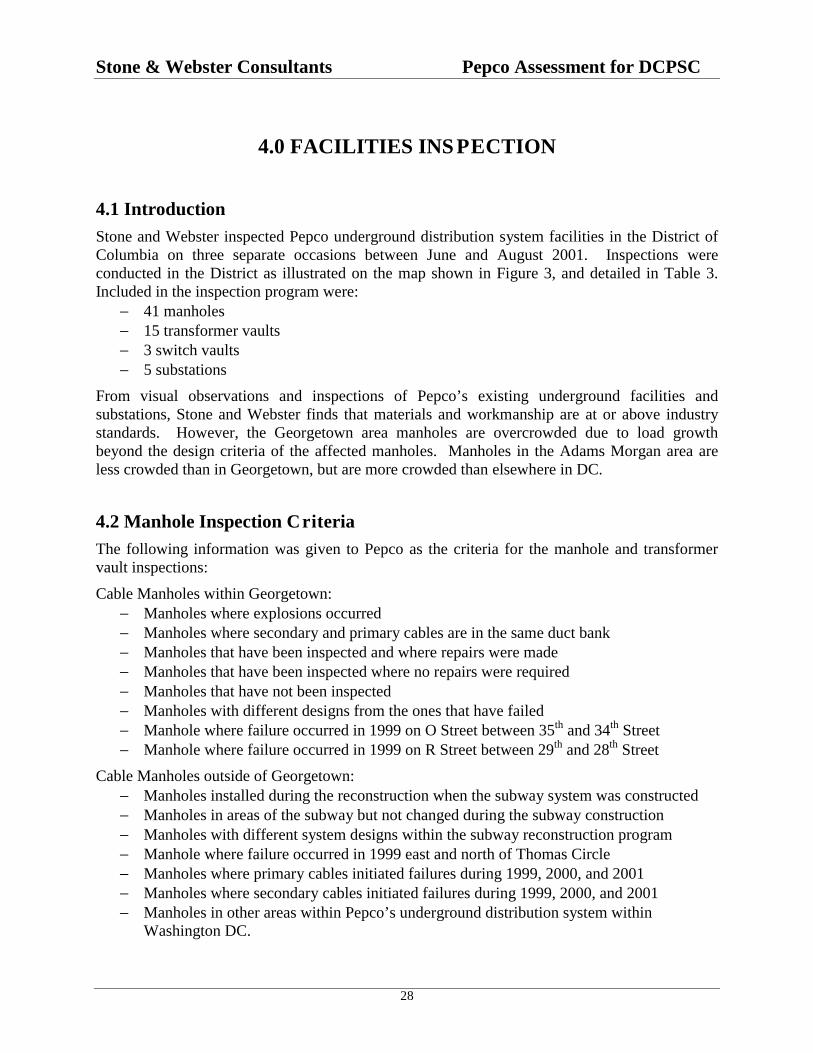
4.1 IntroductionStone and Webster inspected Pepco underground distribution system facilities in the District ofColumbia on three separate occasions between June and August 2001. Inspections wereconducted in the District as illustrated on the map shown in Figure 3, and detailed in Table 3.Included in the inspection program were:
− 41 manholes− 15 transformer vaults− 3 switch vaults− 5 substations
From visual observations and inspections of Pepco’s existing underground facilities andsubstations, Stone and Webster finds that materials and workmanship are at or above industrystandards. However, the Georgetown area manholes are overcrowded due to load growthbeyond the design criteria of the affected manholes. Manholes in the Adams Morgan area areless crowded than in Georgetown, but are more crowded than elsewhere in DC.
4.2 Manhole Inspection CriteriaThe following information was given to Pepco as the criteria for the manhole and transformervault inspections:
Cable Manholes within Georgetown:− Manholes where explosions occurred− Manholes where secondary and primary cables are in the same duct bank− Manholes that have been inspected and where repairs were made− Manholes that have been inspected where no repairs were required− Manholes that have not been inspected− Manholes with different designs from the ones that have failed− Manhole where failure occurred in 1999 on O Street between 35th and 34th Street− Manhole where failure occurred in 1999 on R Street between 29th and 28th Street
Cable Manholes outside of Georgetown:− Manholes installed during the reconstruction when the subway system was constructed− Manholes in areas of the subway but not changed during the subway construction− Manholes with different system designs within the subway reconstruction program− Manhole where failure occurred in 1999 east and north of Thomas Circle− Manholes where primary cables initiated failures during 1999, 2000, and 2001− Manholes where secondary cables initiated failures during 1999, 2000, and 2001− Manholes in other areas within Pepco’s underground distribution system within
Washington DC.

Stone & Webster Consultants Pepco Assessment for DCPSC
29
Substations:− Cables and cable connections, 13 kV units− Cables and cable connections, 4 kV units
Handholes:− Handholes involved with manhole incidents− Handholes with network and/or distribution equipment
Transformer Vaults within Georgetown:− Vaults where manhole incidents from primary cable failures occurred, or in close
proximity to these types of manhole incidents during 1999, 2000, and 2001− Vaults where manhole incidents from secondary cable failures occurred, or in close
proximity to these types of manhole incidents during 1999, 2000, and 2001
Transformer Vaults outside Georgetown:− Vaults where manhole incidents from primary cable failures occurred, or in close
proximity to these types of manhole incidents− Vaults where manhole incidents from secondary cable failures occurred, or in close
proximity to these types of manhole incidents

Stone & Webster Consultants Pepco Assessment for DCPSC
30
Figure 3 Stone & Webster Inspection Locations of Pepco’s Underground DistributionSystem within Washington DC
Locations Inspected 41 manholes 15 transformer vaults 3 switch vaults

Stone & Webster Consultants Pepco Assessment for DCPSC
31
Table 3 Locations of Underground Site Inspections
Type of location Site Location Grid Number
Locations within Georgetown:
Transformer vault Prospect & Potomac St 782390-391576
13 kV, secondary cables with limiters Prospect & Potomac St 782390-313588
13 kV, secondary cables with limiters Prospect & Potomac St 782390-381588
4 & 13 kV Prospect & 35th St 780390-261551
Secondary cables 1562 33rd St 781392-080187
Transformer vault SE side of 33rd & Volta Place 781391-138966
3 Phase Transformer Vault 120/208 Network 31st St in front of Post Office 782390-178340
Manhole next to vault 31st St in front of Post Office 782300-154340
Manhole 31st St & M St, NW 782390-511293
Manhole with primary & secondary cables 31 St & M St 782390-470345
3 Phase Transformer Vault 120/208 Network 29th St & "O" St, NW 783391-328528
3 Phase Transformer Vault 120/208 Network South side Prospect St West ofWisconsin Ave.
781390-974591
Single Phase Transformer Vault 29th St & “R” St NW 783392-365960
Handhole 2810 & 2812 R St. 783392-365965
Manhole 2804 & 2808 R St. 783392-546963
Single Phase Transformer Vault 30th St & “N” St NW 783390-096975
Manhole 1200 36th St NW 779390-890667
Manhole 3500 Prospect St NW 780390-261551
Manhole 35th St & “N” St N.W 780390-246901
Handhole – 120/208 volt M Street near 31st St. 782390-438343
Handhole – 120/208 volt M Street near 31st St. 782390-395342
Handhole – 120/208 volt M Street near 31st St. 782390-326342
Handhole – 120/208 volt M Street near 31st St. 782390-309342
Handhole – 120/208 volt M Street near 31st St. 782390-289342
Handhole – 120/208 volt M Street near 31st St. 782390-270342
4 and 13 kV, 120 V M Street near 31st St. 782390-226341
13 kV and secondary bus M Street near 31st St. 782390-193340
Transformer Vault NW Corner M & 31 Streets 782390-470345
Manhole next to Transformer Vault NW Corner M & 31 Streets 782390-475387

Stone & Webster Consultants Pepco Assessment for DCPSC
32
Type of location Site Location Grid Number
Locations outside Georgetown:
13 kV PILC, Joint had been replaced NW corner of 22nd & G St 785388-991287
13 kV PILC, imploded splice Limiters onsecondary cables
I St between 22nd & 23rd Streets 785388-835642
Metro construction, 13 kV EPR cables 14th St, between O & M 790398-595818
Metro construction, 13 kV & secondary 14th St & Girard 790397-528692
Secondary hole, Cable limiters installed 14th St, Columbia & Irving 790398-594832
3 Phase Transformer Vault 277/480 Network 1900 "K" St, NW Eastside 787389-502127
Bus Hole 277/480 1900 "K" St, NW Eastside 787389-479089
Primary cable manhole 1900 “K” St, NW 787389-502115
3 Phase Transformer Vault 277/480 Network 1111 19th St NW 787389-604979
4 Transformer Vaults 120/208 Network 2500 Virginia Ave. SW 784387-536936
Bus manhole 2500 Virginia Ave. SW 784387-552988
Manhole 400 “D” St SW 794382-964115
Manhole 6th & Pennsylvania Ave. SE 800383-378029
Manhole 500 “I” St NE, North Side 800388-144928
Manhole Manhole in front of substation gate 795382-624425
Manhole Manhole in road near substation 795382-586425
Manhole Manhole 15 ft. north of gate 795382-586411
Switch Hole 17 St NE and East Capitol St SE 803398-430930
Transformer Vault 17 St NE and East Capitol St SE 805384-430971
Bus Hole 2705 13 St & Evarts St NE 803398-348307
Transformer Vault First St NE near Union Station 797388-949379
Secondary Bus Hole 1100 Block of 10 Street NW 792390-570264
Primary manhole 1100 Block of 10 Street NW 792390-590264
Feeder holes, several transformer vaults Eastern Sr. HS, 17th & East Capital 805384-430307
Transformer Vaults 13th St & Evarts St 803398-348324
Transformer Vaults,
Bus hole777 North Capital 797388-949379
797388-961418
Transformer Vaults,
Bus hole810 North Capital
797388-029687797388-023662
Transformer Vaults,
Bus hole,
Primary hole
1100 block 10th St
792390-570264792390-590264792390-530252792390-632264

Stone & Webster Consultants Pepco Assessment for DCPSC
33
4.3 Review of Manholes within GeorgetownIn general, manholes in Georgetown were smaller, more crowded, and were found to containolder style equipment than those outside of Georgetown. This evidence of crowded undergroundfacilities is primarily a result of load growth beyond the originally intended design criteria of themanholes. An example of crowding in Georgetown is the manhole at Thomas Jefferson and MStreets which contains 4 kV primary, 13 kV primary, 208 volt network secondary, 120/240 voltsingle phase secondary, as well as a 4 kV switch and a 4 kV transformer. Street lighting, trafficsignals, and communications cables can also be found in the same Georgetown manholes asprimary and secondary cables.
While it is recognized that these inspections were performed on hot days, it is noteworthy thatthe highest manhole temperatures seemed to be in the smaller more crowded holes. Airtemperatures of 95-98 degrees F were observed.
Georgetown manholes contain more cables of larger wire size than was originally considered intheir design. This presents several kinds of problems. While more cables by themselves lead tomore difficult working conditions in small holes, larger diameter cables are more difficult towork than the smaller wire sizes considered in the original designs. In spite of the crowding, agenerally high quality of workmanship was observed.
Figure 4 shows an example of a crowded manhole in Georgetown. Primary cables, secondarycables, ground (neutral) cables, and either street light or traffic signal wires all come together inone place.
Figure 4 Crowded Manhole within Georgetown with Primary Cables, Secondary Cables,and Traffic Signal or Street Light Cable
Primary
Secondary
Traffic

Stone & Webster Consultants Pepco Assessment for DCPSC
34
Figure 5 shows an example of a crowded hand hole in a sidewalk of Georgetown. Working in ahole like this can be quite difficult because of the lack of space.
Figure 5 Manhole (Handhole) in Georgetown Crowded with Secondary Cables
Secondary Cables

Stone & Webster Consultants Pepco Assessment for DCPSC
35
Many manholes in Georgetown contain both primary and secondary cables, with close spacingbetween primary and secondary cables as illustrated in Figure 6. At this location secondarycables are adjacent to primary cable splices. Should the primary cable splice fail, it is likely toaffect the secondary cables.
Figure 6 Crowded Manhole in Georgetown with Primary and Secondary Cables in VeryClose Proximity
Due to lack of physical space in Georgetown manholes, the primary was not always below thesecondary cables, nor were the secondary cables on an opposite wall from the primary cables.Separation between primary and secondary cables is desirable to reduce the probability of a faultoriginating in a secondary cable from affecting a primary cable (and vice versa), as happened inGeorgetown in the June 13-16, 2001 event.
Secondary Splice
Primary Splice

Stone & Webster Consultants Pepco Assessment for DCPSC
36
A hot (290° F versus the design maximum of 167° F) 208-volt splice was found at the corner ofN and 35th Streets in the Georgetown secondary network system (Figure 7). Bubbling andblistering of the insulation are visible in the picture. The hot splice was called in and repaired bya responding crew. During the repair, the crew found and replaced another splice withdeteriorating insulation. This small, crowded manhole contained both 4kV primary and 208-voltsecondary cables, and is an example of a situation where a primary fault could propagate into asecondary fault and vice versa.
Figure 7 Hot (290o F) Secondary Splice Located During Field Inspection
Blistered Insulation

Stone & Webster Consultants Pepco Assessment for DCPSC
37
Figure 8 shows a section of secondary cable removed during repair of failures in Georgetown.The sample was selected from a large bin of failed cable stored in a warehouse at the BenningService Center. Visual inspection of the cable’s insulation reveals overheating. However, sincethere is no indication of fire damage, the insulation was most likely overheated due to excessiveelectric current.
Figure 8 Overheated Secondary Cable Removed from Georgetown after a ManholeIncident
Bare Conductor

Stone & Webster Consultants Pepco Assessment for DCPSC
38
An example of the use of old-style material in Georgetown manholes is terracotta ductwork,shown in Figure 9. In this example, the terracotta tiles form four square duct holes arranged inan overall square. Different numbers of ducts of different cross-section areas are found indifferent manholes. Although terracotta is a durable material, it is brittle and the joints betweentiles can separate, effectively blocking the duct.
Figure 9 Terracotta Ducts with Primary and Secondary Cables within a Duct Bank
Terracotta Ducts
Primary
Secondary
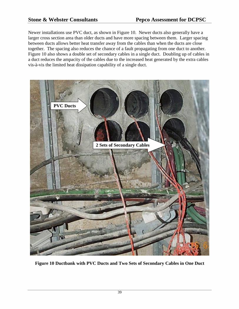
Stone & Webster Consultants Pepco Assessment for DCPSC
39
Newer installations use PVC duct, as shown in Figure 10. Newer ducts also generally have alarger cross section area than older ducts and have more spacing between them. Larger spacingbetween ducts allows better heat transfer away from the cables than when the ducts are closetogether. The spacing also reduces the chance of a fault propagating from one duct to another.Figure 10 also shows a double set of secondary cables in a single duct. Doubling up of cables ina duct reduces the ampacity of the cables due to the increased heat generated by the extra cablesvis-à-vis the limited heat dissipation capability of a single duct.
Figure 10 Ductbank with PVC Ducts and Two Sets of Secondary Cables in One Duct
PVC Ducts
2 Sets of Secondary Cables

Stone & Webster Consultants Pepco Assessment for DCPSC
40
Concern has been expressed about the accumulation of debris in manholes with slotted covers.This concern is justified, as debris was found on the floors of some manholes with slotted covers.Figure 11 shows an example of debris accumulation on the manhole floor. Another example ofdebris accumulation was observed in a manhole on 33rd Street near Q Street, which had a layerof leaves on the manhole floor.
Figure 11 Debris Inside a Manhole With a Slotted Cover
Debris

Stone & Webster Consultants Pepco Assessment for DCPSC
41
4.4 Review of Manholes Outside GeorgetownIn contrast to conditions observed in Georgetown, manholes outside of Georgetown exhibitedmostly larger sizes, newer materials and newer methods. An example of newer materials andmethods is the use of elbow connectors to make connections to the cables. Figure 12 shows asidewalk tap hole using load break elbow connectors. Elbow connectors can be connected anddisconnected without the labor-intensive lead work required on the older PILC wiped joints. Theconnectors can be operated from the sidewalk level above the hole. This construction allowsrapid reconfiguration of the primary cable system for maintenance, repair, or restoration ofservice. Fault indicators are applied on all outgoing cables from the hole, facilitatingidentification of faulted cables. The layout of the tap hole, together with data on the underside ofthe lid is arranged to facilitate rapid operation.
Elbow connectors are an example of methods originally developed for underground residentialdistribution (URD) that are now finding their way into urban systems. The loop system to beinstalled in the Georgetown residential neighborhood to replace the existing 4 kV radial andsecondary network systems is planned to be constructed using these methods. URD derivedmethods offer simplicity and faster restorations following failures.
Figure 12 Tap Hole Showing Load Break Elbow Connectors
Elbow Connectors

Stone & Webster Consultants Pepco Assessment for DCPSC
42
As in Georgetown, a generally high quality of workmanship was observed. Figure 13 shows anexample of high quality workmanship in a secondary bus hole. Note the cable limiters installedon the secondary cables and empty ducts available for future expansion.
Most of the manholes outside of Georgetown are of ample size, with ample separation betweenprimary and secondary cables when it is necessary to place both in the same hole. In such a case,the best approach is to place primary and secondary cables on opposite walls of the manhole,which is done in the Pepco system when possible. One exception to the ample size of manholeswas found in the Adams Morgan area. Some of the manholes in the Adams Morgan area aresmall, and with the area changing from residential to small commercial these manholes maybecome crowded as load increases. In an Adams Morgan-area manhole that had recentlyexperienced an event, Stone and Webster observed Pepco repair crews installing additionalsecondary cable to eliminate overload conditions.
Figure 13 Secondary Bus Hole Showing Quality Workmanship
Cable limiters
Empty Duct

Stone & Webster Consultants Pepco Assessment for DCPSC
43
Figure 14 shows an Adams Morgan manhole while the work was in progress. The present needfor additional cables further raises a concern regarding the future capacity of the undergroundsystem in Adams Morgan. This needs to be resolved by network modeling and analyticalprediction of cable loading for present and future years.
Figure 14 Crowded Adams Morgan Manhole
Primary Cables
Secondary Cables
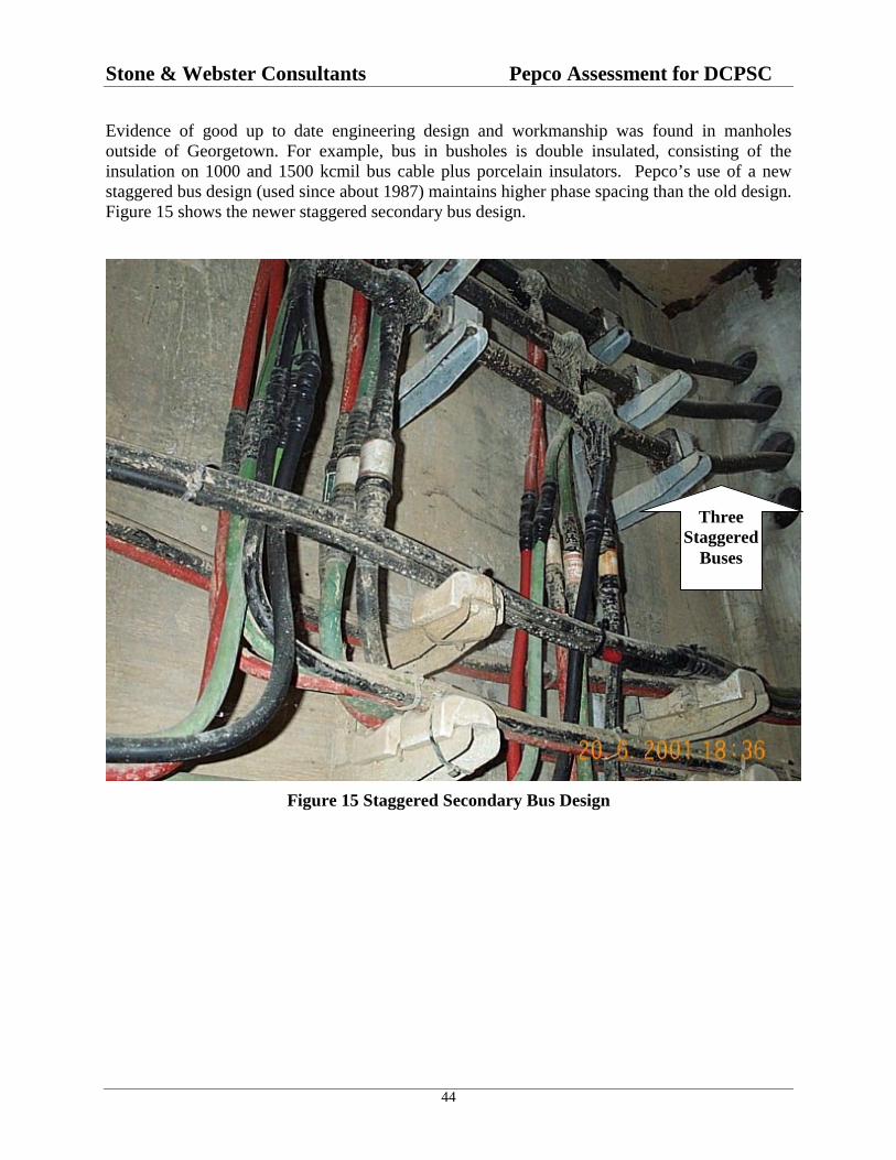
Stone & Webster Consultants Pepco Assessment for DCPSC
44
Evidence of good up to date engineering design and workmanship was found in manholesoutside of Georgetown. For example, bus in busholes is double insulated, consisting of theinsulation on 1000 and 1500 kcmil bus cable plus porcelain insulators. Pepco’s use of a newstaggered bus design (used since about 1987) maintains higher phase spacing than the old design.Figure 15 shows the newer staggered secondary bus design.
Figure 15 Staggered Secondary Bus Design
ThreeStaggered
Buses

Stone & Webster Consultants Pepco Assessment for DCPSC
45
Deficiencies were observed in some of the manholes. For example, two slightly implodedprimary cable lead splices were found. When a lead cable is spliced, the splice is filled with atar-like compound. If insufficiently filled, the lead will partially collapse over time. Figure 16shows an imploded splice. The lead covering the splice should be cylindrical. In this case, theupper surface of the outside lead is indented, appearing like a groove on the top of the splice.While not an immediate concern for failure, imploded splices should be replaced to preventpremature failure. This is an example of the kind of condition the Pepco manhole inspectionprogram is designed to detect and repair.
Figure 16 Imploded Primary PILC Y-Splice
Imploded Area

Stone & Webster Consultants Pepco Assessment for DCPSC
46
While workmanship is generally very good, problems do exist in manholes anywhere. Forexample, Figure 17 shows some additional problems observed in a manhole. The primary cablehas a small tight bending radius that can lead to problems as the cable heats and cools over itsload cycle. Also, the porcelain saddle the cable should rest on is missing. Sliding of the cableover the metal bracket can result in wear on the jacket and possible ingress of moisture andsubsequent failure.
Figure 17 Primary Cables with Small Radius Bend and Missing Porcelain in the Saddle
Small Radius BendSaddle

Stone & Webster Consultants Pepco Assessment for DCPSC
47
4.5 Review of Transformer and Switch VaultsStone and Webster found workmanship in all underground vaults to be good. Especially good isPepco’s present design practice to use a separate vault for each network unit (i.e., networktransformer and its protector), with only one primary feeder into each vault. Use of a separatevault for each network unit is preferable to multiple transformers in the same vault, becauseseparate vaults minimize the chance of a fault in an oil-filled transformer propagating to a secondtransformer or protector. A separate vault is also used for the secondary bus connections, thusseparating primary and secondary facilities as much as possible to contain the consequences ofany faults that may occur. In some cases separate manholes are also used for primary switchesand primary connections. An example of this was at 17th Street NE and East Capitol Street SEby Eastern Senior High School. Each hole in that location is of adequate size and the entireinstallation is laid out to limit collateral damage from a failure.
Newer transformer vaults use elbow connectors to the transformers. Figure 18 shows an elbowconnector at the top left of the tank of a single-phase transformer. Use of elbow connectorsallows simplified connection/disconnection in much the same manner as obtained in the tap holeshown in Figure 12.
Figure 18 Single Phase Transformer Using Elbow Primary Connector
Transformer
Elbow Connector

Stone & Webster Consultants Pepco Assessment for DCPSC
48
An example of a well-designed new transformer vault is given in Figure 19. Note the amplespace and clean layout.
Figure 19 New Transformer Vault with Neatly Arranged Secondary Cables
Secondary Cables
Transformer

Stone & Webster Consultants Pepco Assessment for DCPSC
49
Transformer vaults are covered with a grating for ventilation. These gratings allow entrance ofwater and debris (leaves, etc.) as shown in Figure 20, which shows a flooded transformer vaultwith a layer of leaves on top of the installed equipment. Water is almost up to the top of theprotector. Flooded transformer vaults result in rusting of the transformer tank. Sometransformers at the Benning Service Center that had been removed from service showed severerusting on the lower part of their tanks due to water immersion.
It was observed in the Georgetown residential areas that dual primary voltage transformerscapable of operation at either 4 kV or 13 kV are being installed when transformer replacementsare necessary in the Georgetown radial systems. This is being done to prepare for the plannedconversion from 4 kV to 13.8 kV. This reduces the number of transformers that will need to bechanged when conversion is made from 4 to 13.8 kV as part of the Georgetown plan.
Figure 20 Flooded Transformer Vault with Debris
Water

Stone & Webster Consultants Pepco Assessment for DCPSC
50
4.6 Review of SubstationsThe focus of the Stone and Webster investigation was on primary and secondary cables andassociated manholes. Substations were not the main focus, except as they relate to the cableswhich enter and exit the substations. During the course of the site visits, Stone and Webstervisited five substations, including Substation 12, which supplies Georgetown. The substationswere generally found clean and in good order. However, during one substation visit, an odorsimilar to burning insulation was detected at the substation. This odor was called in, and wasquickly responded to by a Pepco crew.
At one substation it was noted that a 69 kV transmission cable termination was leaking dielectricfluid. Figure 21 shows dielectric fluid being collected by an absorbent material. It should benoted that, based on Pepco’s design criteria, the failure of a single transmission feeder will notresult in customer outages.
Figure 21 69 kV Transmission Cable Leaking Dielectric Fluid
Dielectric Fluid

Stone & Webster Consultants Pepco Assessment for DCPSC
51
The primary feeders at the substations generally show good workmanship (Figure 22). However,problems do occur, such as the leaking primary feeder splice shown in Figure 23, as noted byfluid spots on the lower cables and floor.
Figure 22 Primary Feeders in Substation Showing Good Workmanship
Primary Feeders

Stone & Webster Consultants Pepco Assessment for DCPSC
52
Figure 23 Primary Feeders in Substation with Leaking Splice
Splice
Dielctric Fluid

Stone & Webster Consultants Pepco Assessment for DCPSC
53
5.0 INTEGRITY OF P EPCO’S UNDERGROUNDDISTRIBUTION SYSTEM
5.1 IntroductionOur assessment is primarily based upon an examination of selected Pepco documents, interviewswith Pepco staff, physical inspection of equipment at over 60 locations (i.e., manholes,substations, transformer vaults, and switch vaults), and a review of consultants’ reports, andCommission filings. This assessment reflects our professional judgment and generally considersthe engineering design, construction, materials, operation, maintenance and inspection practicesused by Pepco. However, it does not include an assessment of actual loading on facilities andequipment during normal and/or single contingency conditions (e.g., loss of one feeder) becausePepco has not yet completed the development of the computerized load flow models of its low-voltage network systems needed to perform this analysis. It is noteworthy that the results of suchanalysis of the Georgetown network performed by ABB identified components that aresignificantly overloaded during peak conditions and single contingency conditions.
The main focus of our assessment has been the distribution equipment under the streets andsidewalks of DC. Pepco has two types of underground distribution systems: low-voltagenetwork and radial systems. Low-voltage network refers to systems of low voltage secondarycables that are interconnected in a grid, fed from a multiplicity of network transformers that arefed from multiple 13 kV primary feeder cables. Radial system refers to where the low voltagesecondary cables are not interconnected and use a single 4 kV or 13 kV primary cable. Pepco’sunderground distribution system starts in above-ground substations, and a reliable distributionsystem is dependent on appropriate substations. Therefore, we have included distributionsubstations as part of this assessment.
5.2 SummaryIn general, we find the integrity of major components of Pepco’s underground distributionsystem to be acceptable with the exception of sections of the Georgetown area which arecharacterized by overcrowded manhole facilities and overloading of circuits during both normaland single contingency (e.g., loss of one primary) conditions. The overcrowding andoverloading are due to load growth beyond the design criteria of the affected manholes.However, Pepco’s major modernization plans will correct this condition.
We also find that Pepco has not performed load flow modeling of its low-voltage secondarynetwork system outside of Georgetown, and therefore it is not possible to determine whetherthose circuits are overloaded during normal or single contingency conditions.
5.2.1 Summary of Distributi on Substations
Pepco’s distribution substations in the District of Columbia employ designs, materials, andprotection practices that are equal to or better than those of other metropolitan utilities. Pepco

Stone & Webster Consultants Pepco Assessment for DCPSC
54
designs, constructs, and operates its distribution substations to provide a high level of reliabilityand service continuity.
5.2.2 Summary of Low-volta ge Network Systems
Pepco operates 47 separate low-voltage network systems in the District, generally in commercialareas. The network systems provide the highest level of reliability and service continuitypossible with conventional types of power systems. Pepco’s network systems appear to have theright balance between size, contingency capability, and utilization of equipment capacity.Pepco’s low-voltage network systems are well designed, protected in accordance with or betterthan industry practice, employ equipment and materials that are standard in the industry, andshow good workmanship in transformer vaults, manholes, and bus holes.
The one area where an assessment can not be made is with regard to the actual loading onequipment, especially the low-voltage secondary mains, during normal and single-contingencyconditions. Visual observation of every vault, manhole, or handhole in the system will not revealthe loading on the components during peak conditions, or under contingencies. It is for thisreason that Pepco is strongly encouraged to construct load flow computer models of all of itsnetwork systems. ABB also made this recommendation. These models should be used toevaluate loading of components under both normal and contingency conditions. Prevention ofoverloads may be key to reducing the number of cable faults, and consequently the number ofmanhole incidents.
5.2.3 Summary of Radial Sy stems
Pepco also operates radial distribution systems, generally in residential areas, with 4 kV and 13kV primaries. The 4 kV and 13 kV underground systems are installed in ducts, vaults, andmanholes, similar to those used for the network systems. The practices are consistent with thoseused by other utilities. Pepco recognizes the limits of its 4 kV systems with regard to powerdelivery capability, splicing issues, and outage restoration issues. The 13 kV systems can handlesignificantly higher power loads, utilize newer EPR cable technology that is much easier andfaster to splice together, and the loop system design results in faster customer service restoration.Therefore, Pepco is converting the 4 kV systems to 13 kV as load demand increases. WhenPepco replaces a distribution transformer in a 4 kV system, a dual primary voltage (4 kV & 13kV) unit is employed to allow convenient and cost-effective conversion to 13 kV operation at alater date.
Pepco’s 13 kV radial systems use the latest materials (e.g., primary cables, elbow connectors,splices, fuses, switches, and distribution transformers) available in the industry. The materialshave a proven track record in suburban URD (underground residential distribution) systems.
5.3 Details of the AssessmentThe following sections of this report contain a more detailed discussion of the assessment of theintegrity of Pepco's underground distribution system.

Stone & Webster Consultants Pepco Assessment for DCPSC
55
5.3.1 Distribution Substatio ns
Pepco’s distribution substations supplying loads in the District of Columbia are designed toprovide a high level of reliability and service continuity. The stations will carry the peak loadconnected to the station under any single contingency, that is when:
• there is the outage of any one transmission line into the station
• there is an outage of any one main power transformer in the station
• there is a fault on any one bus section in the station
Pepco has multiple transmission feeds to each distribution substation, multiple powertransformers within the station, and ring-buses that feed the 13 kV primary feeders. Asubstation can have primary feeders for the low-voltage networks, primary feeders for the radialdistribution systems, primary feeders that supply government installations and high-voltagecustomers, and feeders for the METRO system.
5.3.1.1 Ring Bus Design
With the ring bus design, a fault on a section of the 13 kV bus does not cause outages to anycustomer served from the low-voltage network, any METRO installation, and most governmentsites as they frequently employ spot networks or other redundant-type systems within theirfacilities. In comparison, some utilities may have to drop an entire low-voltage network systemfor a fault on a bus section in the station, as they do not employ a ring bus configuration.Furthermore, Pepco operates the 13 kV ring bus with all tie breakers closed. This minimizescirculating currents in the low-voltage network, thereby providing for the optimum operation ofthe network protectors, and very efficient utilization of the network transformer capacity.
5.3.1.2 Metal-Clad Switchgear
Most of Pepco’s distribution substations use metal-clad switchgear, consisting of the 13 kV ringbus, main transformer breakers, feeder breakers, and relays and control equipment. This highlyreliable, factory assembled and tested equipment allows for compact indoor installations, locatedin buildings that blend in with the surrounding architecture. Older switchgear designs employedair-magnetic circuit breakers and electromechanical relays, but in new stations and stationupgrades the new-technology vacuum circuit breakers and microprocessor relays are employed.
5.3.1.3 Relays
Pepco uses extremely sensitive settings for the instantaneous ground current relays for primaryfeeders that supply low-voltage networks. Their settings for the network primary feeders are twoor more times lower than those used by most other utilities. This means that short circuits inprimary feeder cables, feeder splices, and the network transformer are cleared in the fastest timepossible with conventional circuit breakers. In the event that a primary feeder breaker would failto open for a fault on the feeder, backup protection is provided.

Stone & Webster Consultants Pepco Assessment for DCPSC
56
5.3.1.4 Loading Issues
Stone & Webster has not obtained peak loading data on each of the existing distributionsubstations, and has not evaluated and quantified their ability to handle additional load.However, our meeting with the Pepco planning manager revealed that the loading issues arecontinually being addressed, with capacity additions or load transfers between substationsplanned, as needed, to allow single contingency operation.
5.3.1.5 Summary
Pepco’s distribution substations in the DC area employ designs, materials, and protectionpractices that are equal to or better than those of other metropolitan utilities.
5.3.2 Low-voltage Network Systems
Pepco, as many other utilities supplying metropolitan areas, selected the low-voltage networksystem for the commercial and other areas of the city. These systems provide the highest level ofreliability and service continuity possible with conventional types of power systems.
Pepco operates 47 separate low-voltage network systems in the Washington DC area. Each low-voltage network is supplied from six 13 kV primary feeder circuits, and serves a peak load thatwill not exceed about 45,000 kVA (1 kVA is equivalent to a mechanical power of about 1horsepower). Each six-feeder network is designed to carry the peak load with any one primaryfeeder out of service. This single-contingency design practice is used by all utilities for thedesign of their low-voltage networks, with the exception of one. That is, Consolidated Edison ofNew York designs systems that will not overload when any two primary feeders are out ofservice during peak loading (double contingency design). This is possible because their low-voltage networks are much large than 45,000 kVA, and because they have a much larger numberof primary feeders supplying each network. The downside of that approach is that, should amajor catastrophe develop, the amount of load dropped may be more than 200,000 kVA, andnetwork restoration is more difficult with the larger networks. In comparison, in Pepco’s systema major catastrophe will not drop more the 45,000 kVA of load.
Pepco’s low-voltage network systems appear to have the right balance between size, contingencycapability, and utilization of equipment capacity.
5.3.2.1 Paper Insulated Lead Cov ered Cables
The primary feeders of Pepco’s low-voltage networks use paper insulated lead covered (PILC)cables. Recently, they have changed to EPR insulated cables for the exits from the substations,as this type of cable results in a simpler and reliable termination of the cable to the switchgearbuses in the distribution substation. Similarly, they have changed from PILC cables to EPRcables and elbow connectors for making connections to the high-voltage terminals of thenetwork transformers. This eliminates the lead-wiped terminations that are expensive to makeand require skilled workers. This allows for greater operating flexibility, should a networktransformer need to be changed. Pepco, like some other utilities, is evaluating the use of EPRcables for all applications in the primary feeders of their networks, with ongoing work to developsuitable means for making transition “Y” splices between EPR and PILC cables.

Stone & Webster Consultants Pepco Assessment for DCPSC
57
5.3.2.2 Manhole Conditions
Ideally, a manhole should have just one 13 kV primary feeder and no secondary cables in thesame manhole as a primary feeder. No utility has this luxury. Thus multiple primary feeders ina manhole plus secondary cables is typical. For these manhole conditions, Pepco tries toseparate the primary and secondary circuits such that an arc in the secondary does not burn into aprimary cable. When this is not possible, the secondary cable is located above the primarycables in order to minimize the probability of a secondary failure propagating into the primarycables. Very small and crowded manholes can be found in old parts of the Pepco system, asobserved in Georgetown. However, manholes constructed to newer standards are much larger,simplifying the installation and splicing of cables.
5.3.2.3 Transformer Vaults
Pepco places just one network transformer/protector in an underground vault, the preferredpractice, as a failure will not propagate to other portions of the system. In contrast, some utilitiesplace multiple transformers/protectors in the same vault, an arrangement that can result in doublecontingencies during faults, and loss of the entire network. Furthermore, in Pepco’s system, theparalleling bus for multiple transformers is in a separate vault, referred to as a bus hole. Incomparison, some utilities will place the paralleling bus in the same vault that has thetransformers/protectors, clearly a less reliable design. The use of a separate bus hole for theparalleling bus is preferred, offering higher reliability.
Our inspection of transformer vaults and bus holes in the Pepco system revealed goodworkmanship in the installation of low-voltage secondary cables. The neatness of the workshows good craftsmanship and pride on the part of the workers installing the system. Thestaggered arrangement of the phases in the paralleling bus in the bus holes produces a bus withhigh reliability, as the insulated conductors of different phases are separated with air.
5.3.2.4 Cable Limiters
Pepco's design practice is to install cable limiters on most sets of low-voltage cables, but not on250 kcmil secondary cables unless the available current into the fault from both sides is less than3200 amperes. In contrast, some utilities install limiters on all secondary cables, and there areutilities that do not install any limiters on the secondary cables. Pepco is encouraged to re-evaluate its design standards with regards to the application of cable limiters on single sets of250 kcmil secondary cable mains, for future additions to its system.
5.3.2.5 Materials
The basic materials that Pepco purchases for their low-voltage network system are in accordancewith industry standards such as the American National Standards Institute (ANSI) and with thoseused by other utilities. Included are the metal-clad switchgear for the distribution substations,the primary and secondary cables, and the network transformers and network protectors. Pepcois one of the few utilities that purchase color-coded low-voltage cables, which aids in installingand trouble shooting the secondary systems. Although terra cotta ducts are found in old portionsof the system, more modern materials have been used for duct bank construction in recent years.
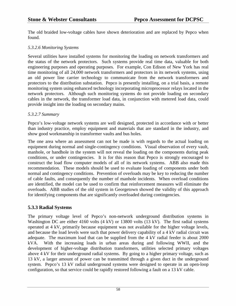
Stone & Webster Consultants Pepco Assessment for DCPSC
58
The old braided low-voltage cables have shown deterioration and are replaced by Pepco whenfound.
5.3.2.6 Monitoring Systems
Several utilities have installed systems for monitoring the loading on network transformers andthe status of the network protectors. Such systems provide real time data, valuable for bothengineering purposes and operating purposes. For example, Con Edison of New York has realtime monitoring of all 24,000 network transformers and protectors in its network systems, usingan old power line carrier technology to communicate from the network transformers andprotectors to the distribution substation. Pepco is presently installing, on a trial basis, a remotemonitoring system using enhanced technology incorporating microprocessor relays located in thenetwork protectors. Although such monitoring systems do not provide loading on secondarycables in the network, the transformer load data, in conjunction with metered load data, couldprovide insight into the loading on secondary mains.
5.3.2.7 Summary
Pepco’s low-voltage network systems are well designed, protected in accordance with or betterthan industry practice, employ equipment and materials that are standard in the industry, andshow good workmanship in transformer vaults and bus holes.
The one area where an assessment can not be made is with regards to the actual loading onequipment during normal and single-contingency conditions. Visual observation of every vault,manhole, or handhole in the system will not reveal the loading on the components during peakconditions, or under contingencies. It is for this reason that Pepco is strongly encouraged toconstruct the load flow computer models of all of its network systems. ABB also made thisrecommendation. These models should be used to evaluate loading of components under bothnormal and contingency conditions. Prevention of overloads may be key to reducing the numberof cable faults, and consequently the number of manhole incidents. When overload conditionsare identified, the model can be used to confirm that reinforcement measures will eliminate theoverloads. ABB studies of the old system in Georgetown showed the validity of this approachfor identifying components that are significantly overloaded during contingencies.
5.3.3 Radial Systems
The primary voltage level of Pepco’s non-network underground distribution systems inWashington DC are either 4160 volts (4 kV) or 13800 volts (13 kV). The first radial systemsoperated at 4 kV, primarily because equipment was not available for the higher voltage levels,and because the load levels were such that power delivery capability of a 4 kV radial circuit wasadequate. The maximum load that can be supplied from the 4 kV radial feeder is about 2000kVA. With the increasing loads in urban areas during and following WWII, and thedevelopment of higher-voltage distribution transformers, utilities selected primary voltagesabove 4 kV for their underground radial systems. By going to a higher primary voltage, such as13 kV, a larger amount of power can be transmitted through a given duct in the undergroundsystem. Pepco’s 13 kV radial underground systems were designed to operate in an open-loopconfiguration, so that service could be rapidly restored following a fault on a 13 kV cable.

Stone & Webster Consultants Pepco Assessment for DCPSC
59
Pepco’s 4 kV systems operate in a radial fashion, use lead sheath primary cables and lead sheathsecondary cables in some instances, oil fused cutouts on the 4 kV circuits for protection, andsingle-phase distribution transformers. To connect the cables of the 4 kV system to oil fusedcutouts (immersed in oil) and to distribution transformers requires making of wiped leadedconnections, an expensive and time consuming process requiring a skilled worker. The same istrue when splicing 4 kV lead-sheath cables. These characteristics of Pepco's 4 kV undergroundsystems are consistent with most other 4 kV underground systems in the country, because thenewer materials used in the 13 kV systems were not available when the 4 kV systems wereengineered. As the 4 kV systems operate in a radial fashion, a fault on the 4 kV primary feederscan result in long duration outages for many customers. This is due to the time required to locatethe faults and perform the repairs that are necessary before service can be restored.
In contrast, Pepco’s 13 kV distribution systems employ an open loop design, where in effect tworadial feeders are connected by a normally open switch or connection. This normally openswitch or connection allows the 13 kV systems to operate in a radial fashion, just as the 4 kVsystems. However, should a fault occur on a feeder, the supply can be reconfigured, usuallyallowing service to be restored to all customers in a much shorter time. This is because the open-loop design permits service restoration without need to repair the faulted 13 kV primary cable.Rapid restoration of service to all customers is achieved by isolating the fault and closing the“open loop” connection. This is made possible by using non-lead sheath construction for cables,and by making connections to distribution transformers, switch cabinets, and fuse cabinets withelbow connectors (separable connectors). With these types of connectors, 13 kV cableconnections can be easily made and broken, similar to plugging and unplugging extension cordsused in residences. Elbow connectors are mature products developed initially for use inunderground distribution systems in suburban areas.
In Pepco’s 13 kV system, a cable fault is found much faster than in its present 4 kV system,because permanently installed fault indicators are used with the non-leaded 13 kV cables. Thetechnology of the fault indicators is not applicable to systems using lead sheath cables andconsequently the fault indicators cannot be applied in the 4 kV systems. Once the fault islocated, the cables on either side of the fault are opened with the elbow connectors, or switches ifinstalled. Then the system on either side of the fault can be re-energized without need for animmediate repair of the fault. This is possible because of the open loop design used for 13 kVprimary circuits described above. Furthermore, within the 13 kV system are oil switches that areinstalled to allow reconfiguration of the system. In addition, Pepco’s 13 kV system utilizes fusesin submersible enclosures to allow isolating only the faulted section of the primary feeder,without opening the entire feeder at the substation. The overall advantage derived from Pepco's13 kV design practices (e.g., non-leaded cables, elbows or separable connectors, fault indicators,switches, and fuse cabinets), is that the reliability of the 13 kV systems is higher than that of the4 kV systems.
Pepco’s 13 kV open-loop system design reflects industry recognized concepts that provide forfast fault location, isolation, and restoration of service.
The 4 kV and 13 kV systems are installed in ducts, vaults, and manholes, similar to those usedfor the network systems. The practices are consistent with those used by other utilities. Pepcorecognizes the limits of its 4 kV systems, and when a distribution transformer is replaced in these

Stone & Webster Consultants Pepco Assessment for DCPSC
60
systems, a dual primary voltage unit (4 kV/13 kV) is employed to allow convenient and cost-effective conversion at a later date to 13 kV operation when required by loading levels.
Pepco’s 13 kV radial systems use the latest materials (primary cables, elbow connectors, splices,fuses, switches, distribution transformers) available in the industry. The materials have a proventrack record in suburban URD (underground residential distribution) systems. Furthermore,determining loading of equipment in the radial distribution systems is a relatively simple matter.The load at any point is found by the addition of the diversified demands of each customerbeyond the point of interest. In comparison, in the low-voltage network systems, loading can befound only by developing models of the network suitable for use in the load flow program.

Stone & Webster Consultants Pepco Assessment for DCPSC
61
6.0 POWER FLOW M ODELING
6.1 IntroductionThe electric power transmission system consists of a complex network of lines containing manyparallel paths. A similar situation occurs in a low voltage network distribution system wherethere are multiple secondary cable paths between two points on the system. The complexity ofthe secondary network is shown in the diagram of the Georgetown East Network in Figure 24below. Also shown are multiple parallel paths to the loads, as illustrated by the multiple squares.
When there are parallel paths, the power flow divides among them according to the relativeelectrical impedances of the paths. The flow in one line or cable can be affected by flows in therest of the system. From a calculation standpoint, the situation gets more complicated whenthere are voltage regulators or transformer tap changers. The consequence of this is that it isimpossible to guess how the power divides among the different cables, and some form ofanalysis is necessary. This is called the “load flow” problem and has been the subject ofdevelopment and study for decades.
At the distribution level, the main parameters are the electrical resistance and reactance of eachline or cable. These are mathematical parameters derived from calculation or measurement.Because of the sheer number of lines/cables and buses, the problem quickly becomes beyond theability of calculation by hand, even without the nonlinearities caused by voltage regulators andtap changers.
6.2 Development of Analytical ModelingThe first attempt to solve the calculation problem was the “dc calculating board.” In this devicethe resistance of lines was neglected and only the reactances were modeled. The limitations ofthis method led to the development of the “ac calculating board,” also called the “ac networkanalyzer.” This was a large analog computer, which contained units representing lines, loads,transformers, and generators. Connections were made with plug boards resembling oldfashioned telephone switchboards. A large room full of equipment was required to model 100buses, and a significant amount of time was required to set up a base case for a study. The acnetwork analyzer reached the highest state of development in the 1950’s. Network analyzerswere installed at manufacturers such as General Electric and Westinghouse, and at universities.For example, Niagara Mohawk Power Corporation and New York State Electric and Gascombined to install a network analyzer at Syracuse University.
Development of digital computers soon rendered the ac network analyzer obsolete, and by theend of the 1960’s it was little used. Early computer load flow programs were developed byGeneral Electric, Westinghouse, and Philadelphia Electric. The 1960’s versions ran on batchcomputers and required input on punch cards and paper output. The development of timesharing and mini computers (in a 6 foot rack at the time) allowed development of load flowprograms that did not require a mainframe computer. Power Technologies, Inc., (PTI) ofSchenectady developed the Power System Simulator program PSS/2 for use on Hewlett Packard

Stone & Webster Consultants Pepco Assessment for DCPSC
62
mini computers about 1970, and the later PSS/E for time sharing and later personal computer(PC) use about 1975. The capabilities and ease of use have increased with each update. Otherload flow programs have become available in recent years, for example the EasyPower programpurchased by Pepco.
6.3 Analytical Modeling of Secondary NetworksThree digital computer programs were available in the 1960’s: GE, Westinghouse, andPhiladelphia Electric. During the 1960s Dave Smith of the Stone & Webster team modeled thesecondary networks for the City of Richmond, Indiana electric utility using the Westinghouseload flow program. Niagara Mohawk Power first modeled its network systems in the early1960s using a technology with very limited node capacity. During the late 1960s, NiagaraMohawk used the Philadelphia Electric program.
During the 1970s, PTI developed and made commercially available its Power SystemSimulator/Engineering (PSS/E) program, which has been used to model secondary networks byAlabama Power, Northern States Power, Portland General Electric, Niagara Mohawk Power andothers. Much of this work started in the 1980s.
Pepco purchased the PSS/E program in November 1977 for studies related to its transmissionsystem, but evidently did not use it to model its secondary networks. The EasyPower program,which Pepco recently purchased and has begun to use, was made commercially available in theearly 1990s. Virginia Power began using EasyPower during the early 1990s. Previously,Virginia Power had used the Philadelphia Electric program.
6.4 Pepco Secondary Network Analytical ModelingBecause Stone & Webster had been informed that Pepco had not modeled its secondarynetworks, the 5th Stone & Webster data request asked:
"Provide a narrative or a description of the procedures, methodologies, or calculationsthat are presently employed by Pepco when designing a secondary network system, andwhen evaluating the performance of an existing secondary network system to determineif the components of the system will be loaded above their rating under both normalconditions and single contingency conditions."
Pepco's response referred to its design standards, which contained nothing about planning oranalysis tools, methods, or procedures. However, during a team interview session held withPepco at its Benning Service Center, Pepco stated that the Company uses a program that is onlycapable of analyzing about a three-block area.
In order to address this need, Pepco contracted with ABB to develop analytical models of theGeorgetown secondary network systems and 4 kV radial distribution system. ABB developedthe models using their own load flow program, performed an analysis of the Georgetownsystems, and produced the following two final reports:
• “Georgetown Area Network System Evaluation,” ABB Final Report May 21, 2001
• “4 kV System Load Flow and Reliability Analysis,” Final Report March 9, 2001

Stone & Webster Consultants Pepco Assessment for DCPSC
63
Figure 24 was taken from the “Georgetown Area Network System Evaluation” report.
Figure 24 Georgetown East Network Load Flow Results from ABB Report
The intention of Pepco's design criteria for its network systems is to be able to operate at systempeak without overloading secondary cables, even with one feeder out of service. From theresults of the ABB secondary network load flow analysis, the Georgetown East and Northnetworks are not able to handle peak load conditions without overloading some secondarycables, even with all primary feeders in service. The red line in Figure 24 is a section ofsecondary cable in the Georgetown East Network that is overloaded as a result of a singlecontingency (single primary feeder out of service). This is a result that is available because ofanalytical network simulation and is not intuitively evident or amenable to hand calculation.
During other contingencies many secondary cables can be severely overloaded as well as somenetwork transformers. This is the most significant result of the ABB analysis, because secondarycables have been implicated in a number of manhole incidents. This finding also raises concernsabout the performance of the remaining network systems in DC, which emphasizes the need toexpedite the underground network modeling.
ABB analyzed the performance of the Georgetown 4 kV system based on reliability indices andload flow analysis. The study supports Pepco’s decision to convert the 4 kV radial distributionsystem in the residential area of Georgetown to a 13 kV loop system. Overall, the study found:
− The reliability indices (SAIDI, SAIFI) of the 4 kV radial distribution system inGeorgetown reflect substandard performance. The 5-year record of outage statisticsindicates significantly higher failure rates than experienced in new underground systems.

Stone & Webster Consultants Pepco Assessment for DCPSC
64
− Overloaded 4 kV cables under peak system load conditions.− A primary feeder with a voltage drop in excess of 4%.
The results of the ABB load flow analyses in Georgetown show the need for Pepco to develop ananalytical model of all their secondary networks as quickly as possible. These models areneeded both to identify possible overloads in the existing system and to properly plan forexpansion. Once developed and implemented, an analytical model is a powerful tool forpredicting the impact of load growth on the network and for developing long-range systemenhancement and strategic plans.

Stone & Webster Consultants Pepco Assessment for DCPSC
65
7.0 RECENT TECHN OLOGIES
7.1 Fault Current-Limiting DevicesData from Pepco and other utilities surveyed by ABB in its study for Pepco show that morefaults occur on the primary feeders of secondary networks than in the low-voltage cables.Further, faults in primary cable splices have resulted in ejection of manhole covers.
Researchers suggest that the high pressures that eject manhole covers may be caused by twoseparate mechanisms for faults in the splices of PILC cables. One is the ignition of gasesgenerated when the splice insulating materials become decomposed from heating due to tracking.The other is from the heating of air and volatilization of conductor material during the ensuinghigh-current arc.
The first mechanism, involving a partial breakdown of the splice insulation, is insufficient byitself to result in a power arc and consequent circuit breaker operation. This mechanism is called“tracking,” and is characterized by lines engraved in the splice insulation. The electricaldischarge that causes insulation tracking creates heat. The heat and electrical discharge generatecombustible gases from decomposition of the insulation. If these gases are ignited, they mayresult in an explosion of a magnitude sufficient to lift a manhole cover. In this case, the manholeexplosion is a consequence of a chemical gas explosion, and the use of current-limiting devicesprobably would not be effective in preventing manhole cover ejections from faults in cablesplices.
In the second mechanism, the manhole cover lifts as a result of gas pressure created from energycontained in the fault arc. In this case, current-limiting devices may possibly prevent manholecover ejections by reducing the amount of energy liberated in the manhole by the arc itself.
When a fault path develops in a splice of a high-voltage cable, the resulting power arc has veryhigh currents that flow from the substation to the fault until the circuit breaker at the substationopens. Even after the station circuit breaker opens, fault currents may continue to flow in thefault until all backfeeding network protectors open. Any changes in system design or protectionthat reduce the magnitude of the available fault current, and any changes that reduce the time thatthe current flows will reduce the energy into the fault, and the pressures generated in themanhole.
Figure 25 shows the current flow from the substation to a fault in a splice when current-limitingdevices are not installed (heavy curve), assuming a 5 cycle clearing time typical of the Pepcosystem. The lighter curve in Figure 25 is representative of the current that flows in the faultedphase from the substation to the fault when current-limiting devices are installed in the feeder atthe substation. The current-limiting device limits not only the duration of the current flow in thefaulted phase, but also the peak magnitude of the current flow when the available fault currentsare high. Reduced fault current magnitude and duration mean the current-limiting device canresult in a significant reduction in energy input to the fault.
Unfortunately, there appears to be no formal research on the relationship between pressuresgenerated in the manhole for primary cable faults and the electrical energy input to the fault arc
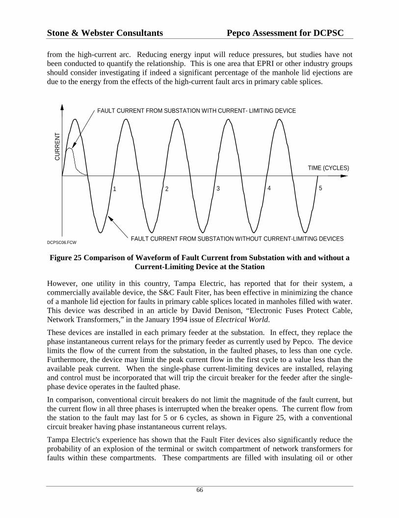
Stone & Webster Consultants Pepco Assessment for DCPSC
66
from the high-current arc. Reducing energy input will reduce pressures, but studies have notbeen conducted to quantify the relationship. This is one area that EPRI or other industry groupsshould consider investigating if indeed a significant percentage of the manhole lid ejections aredue to the energy from the effects of the high-current fault arcs in primary cable splices.
FAULT CURRENT FROM SUBSTATION WITHOUT CURRENT-LIMITING DEVICES
CU
RR
EN
T
TIME (CYCLES)
1 2 3 4 5
FAULT CURRENT FROM SUBSTATION WITH CURRENT- LIMITING DEVICE
DCPSC06.FCW
Figure 25 Comparison of Waveform of Fault Current from Substation with and without aCurrent-Limiting Device at the Station
However, one utility in this country, Tampa Electric, has reported that for their system, acommercially available device, the S&C Fault Fiter, has been effective in minimizing the chanceof a manhole lid ejection for faults in primary cable splices located in manholes filled with water.This device was described in an article by David Denison, “Electronic Fuses Protect Cable,Network Transformers,” in the January 1994 issue of Electrical World.
These devices are installed in each primary feeder at the substation. In effect, they replace thephase instantaneous current relays for the primary feeder as currently used by Pepco. The devicelimits the flow of the current from the substation, in the faulted phases, to less than one cycle.Furthermore, the device may limit the peak current flow in the first cycle to a value less than theavailable peak current. When the single-phase current-limiting devices are installed, relayingand control must be incorporated that will trip the circuit breaker for the feeder after the single-phase device operates in the faulted phase.
In comparison, conventional circuit breakers do not limit the magnitude of the fault current, butthe current flow in all three phases is interrupted when the breaker opens. The current flow fromthe station to the fault may last for 5 or 6 cycles, as shown in Figure 25, with a conventionalcircuit breaker having phase instantaneous current relays.
Tampa Electric's experience has shown that the Fault Fiter devices also significantly reduce theprobability of an explosion of the terminal or switch compartment of network transformers forfaults within these compartments. These compartments are filled with insulating oil or other

Stone & Webster Consultants Pepco Assessment for DCPSC
67
insulating compounds. Such a fault did occur in the terminal compartment of a 500 kVAtransformer in the Pepco Georgetown network, located at 29th and O Street. The fault rupturedthe terminal compartment, resulting in a small oil fire. Furthermore, it is recognized that shoulda fault occur within the switch compartment or the terminal compartment of a networktransformer, it is quite likely that the cover plate will be partially or completely blown off whenthe fault is cleared with a conventional circuit breaker at the substation.
Pepco should determine whether commercially available current-limiting devices, like the S&CFault Fiter, the G&W CliP, or similar devices are applicable to the primary feeders of its networksystems. In evaluating the installation of current-limiting devices in network primary feeders atthe substation, the following additional areas need to be considered.
• Application when capacitor banks are located in the substation
• Impact on grounding network primary feeders in the substation using a grounding and testdevice in metal-clad switchgear located at the substation
• Impact on phase and ground relaying for the network primary feeders, and relaying needed toprevent single phasing of the circuit when the current-limiting device operates
• Impact on network protector relaying for faults on the primary feeders
• Effect on reliability (false operation)
• Space requirements and availability in existing substations
7.2 Advantages of Fault-Limiting Devices in Pepco’s SystemPepco supplied data for three-phase and single line-to-ground fault currents on the 13.8 kV busesthat supply the network feeders in the Pepco system. The data shows that the available faultcurrents on the buses are very high. Pepco does not install phase reactors at the substation inprimary feeders for secondary networks. This means that currents for feeder faults close to thesubstation are the same as for a fault on the substation bus.
As a result, if current-limiting devices were installed in the network primary feeders at thesubstation, such as the S&C Fault Fiter or the G&W CLiP, they would result in a significantreduction in energy into faults in the splices of PILC cables. This in turn reduces the likelihoodof a displaced manhole cover from the pressures generated by high-current arcing in the splice.
Further, current-limiting devices would result in a significant reduction in energy into faults inthe terminal compartment and high-voltage switch compartment of network transformers. Thisreduces the likelihood of rupturing the compartment and creating an oil fire, as occurred inGeorgetown at 29th and O Streets on May 02, 2001. If the available fault currents were low, theapplication of the current-limiting device would not result in as large a reduction in energy.
The ground relay settings used by Pepco on its dedicated network feeders for low-voltagenetworks are extremely sensitive, allowing for sensitive detection of ground faults in the primarywindings of network transformers, and the shortest possible clearing time from the substationwhen conventional circuit breakers are used. The phase instantaneous current relay settings forPepco’s dedicated network feeders are in a range which suggests that current-limiting devices,

Stone & Webster Consultants Pepco Assessment for DCPSC
68
such as the S&C Fault Fiter, or the G&W Clip could be applied, so long as other applicationconstraints are not present.
These fault current values, in conjunction with the relay settings used by Pepco, furthersubstantiate the recommendation that Pepco should evaluate the applicability of the current-limiting devices to their system.
7.3 Fault Location Time in Network SystemsEach of Pepco’s low-voltage networks has six 13,800 volt primary feeder circuits. When a faultoccurs on any one primary feeder circuit, it is automatically isolated, and the remaining fiveprimary feeders carry the load of the network. When this happens, the load on the remainingfive feeders will increase about 20 % or more, depending on the interlacing of the feeders and theload distribution. The corresponding resistive losses and heating on some primary feeder cableswill go up by as much as 44 %. Furthermore, in the 208-volt grid network the loading onsecondary cables will increase.
Operating at higher loading levels increases the likelihood of a failure occurring in a secondcomponent of the system, and in turn causing a manhole event or an outage.
It is therefore important that faults on network high-voltage primary feeders are rapidly locatedand repaired, and the high-voltage primary feeder placed back into service as soon as possible.At present, Pepco uses sheath coils to pre-locate faults on primary feeders, and picks to pinpointthe fault location on feeders with PILC cable. This can be a time consuming process, as itrequires opening manholes so that personnel can enter to make measurements. If a manhole isflooded, additional delays are incurred until the water is removed.
Some newer technologies and equipment have recently been developed for locating faults onnetwork primary feeder circuits for Con Edison, the operator of the largest low-voltage networksystems in the world. The particular device that Con Edison is presently using is the “aboveground” meter, which allows pre-location of the fault without the need to open and entermanholes. The device was originally developed by AT&T Bell Laboratories, and is nowavailable in commercial form from the Technology Enhancement Corporation. The operator ofthe above ground meter need only travel the route of the primary feeder to locate the fault,without need to enter manholes.
In addition, real-time fault location schemes are also being developed for Con Edison. Withthese schemes, the objective is to have a system that will tell system operators, almostinstantaneously after feeder breaker opening, the distance of the fault from the substation orsome other reference point.
7.4 Isolated Spot NetworksPepco operates isolated spot networks in the DC area. An isolated spot network consists of twoor more network units installed at the same location. A network unit consists of a networktransformer and a network protector. The load terminals of the network protectors are connectedto the paralleling bus located in the bus hole, adjacent to the vaults with the network units.Customer loads are fed from service cables connected to the paralleling bus in the bus hole. In
Stone & Webster Consultants Pepco Assessment for DCPSC
69
the isolated spot network system, there are no ties to the low-voltage secondary mains located inthe streets. Multiple sources provide the reliability expected of a network system.
In order for the spot network to provide the highest level of reliability, all network protectorsshould be closed whenever the associated high-voltage (HV) primary feeder is energized. Thatway, the disturbance to the load supplied from the spot network, if any, will be minimized for afault on one of the HV primary feeders of the spot network. Whenever a high-voltage feeder istaken out of service for maintenance or system modifications, the network protectors associatedwith that feeder open. This creates the condition where not all network protectors in the spotnetwork are closed. Whenever the feeder is subsequently re-energized, it is desired that the openprotectors automatically close under the proper conditions that will not result in an ensuingreverse power and another tripping of the protector.
Relays control the automatic reclosing of network protectors. Prior to the development ofmicroprocessor relays for network protectors, automatic reclosing was controlled with twoseparate electro-mechanical relays. These relays had “straight-line close characteristics,” whichset the conditions under which the relay operated. With the most recent microprocessor relays fornetwork protectors, the user can select the type of close characteristic that the relay will exhibit,either straight line or “circular.” The circular close characteristic allows the protector to close ata lower load on the network, thereby helping to keep all network protectors closed regardless ofthe load on the spot network. This in turn enhances the reliability of the network system. Thecircular close characteristic is recommended for use in network protectors for isolated spotnetworks
7.5 Recommendations on New Technologies
7.5.1 Recommendation No. 1
Pepco should evaluate the effectiveness of high-voltage current-limiting devices installed in eachprimary feeder at the substation as a means of reducing the probability of a fault in a primarycable splice causing a manhole explosion (manhole lid displacement).
Tampa Electric has installed these devices and has found them to be very effective for thispurpose in their low-voltage network systems. Tampa Electric has also determined that thesedevices are effective in preventing the rupture of cable terminal compartments and switchcompartments on the high-voltage side of network transformers, events which can result in oilfires in transformer vaults.
7.5.2 Recommendation No. 2
Pepco should evaluate the applicability of new technologies for locating faults on the high-voltage feeder cables of the low-voltage network systems. The faster a fault on a high-voltagefeeder cable can be located and repaired, the shorter the duration of the higher loading placed onthe other components of the low-voltage network system. This reduces the likelihood that a faulton one high-voltage feeder circuit will cause a second fault in another cable due to overloading.Pepco’s low-voltage network systems, like those of most other utilities, may overload when twohigh-voltage primary feeders are out of service.
Stone & Webster Consultants Pepco Assessment for DCPSC
70
Specifically, Pepco should evaluate some of the newer technologies and equipment recentlydeveloped for locating faults on network primary feeder circuits developed for Con Edison, theoperator of the largest low-voltage network systems in the world. The particular device that ConEdison is presently using is the “above ground” meter, which allows pre-location of the faultwithout the need to open and enter manholes. The device was originally developed by AT&TBell Laboratories, and is now available in commercial form from the Technology EnhancementCorporation. The operator of the above ground meter need only travel the route of the primaryfeeder to locate the fault, without need to enter manholes.
In addition, Pepco is encouraged to monitor the progress being made on real-time fault locationschemes being developed for Con Edison. With these schemes, the objective is to have a systemthat will tell system operators, almost instantaneously after feeder breaker opening, the distanceof the fault from the substation or some other reference point. When such devices or systemsbecome available, Pepco is encouraged to evaluate their applicability to the Pepco low-voltagenetwork systems.
7.5.3 Recommendation No. 3
Pepco is installing newer microprocessor relays in the isolated spot networks. By programmingthese relays, Pepco can select either a circular close characteristic or a conventional straight-lineclose characteristic. Pepco is encouraged to consider the application of the circular closecharacteristics in each spot network whenever the microprocessor relays are incorporated into allprotectors in the spot network to increase circuit reliability.
Stone & Webster Consultants Pepco Assessment for DCPSC
Appendix A71
APPENDIX A
ANALYSIS OF REPORTS & FILINGS PREPARED BY PEPCO &ITS CONSULTANTS
Contents
1. REVIEW OF Final Report on Manhole Event Tests for Pepco at Lenox EPRI Final ReportWO-049296
2. REVIEW OF Report of Potomac Electric Power Company in Response to CommissionOrder No. 12036
3. REVIEW OF Georgetown Area Low-Voltage Network ABB Final Report Dated January 15,2001
4. REVIEWS OF Georgetown Area Network System Evaluation ABB Final Report May 21,2001 And 4 kV System Load Flow and Reliability Analysis Final Report March 9, 2001
5. Pepco’s Original and Revised Priority Definitions - Manhole Reliability Inspection

Stone & Webster Consultants Pepco Assessment for DCPSC
Appendix A72
Appendix A.1
REVIEW OF
Final Report on Manhole Event Tests for Pepco at Lenox
EPRI Final Report WO-049296
Prepared by Stone & Webster Consultants
For the Public Service Commission of the District of Columbia
Submitted September 13, 2001
A.1.1 Purpose of This DocumentAt the request of the Public Service Commission of the District of Columbia, Stone & Websterreviewed the document “Final Report on Manhole Event Tests for Pepco at Lenox,” EPRI FinalReport WO-049296, October 2000, and the two earlier EPRI reports cited as References 1 and 2in EPRI report WO-049296. A Stone & Webster consultant also attended the “Manhole/VaultEvent Summit Workshop,” sponsored by EPRI held August 30-31, 2001 in Washington, D.C.
A.1.2 Purpose of the EPRI StudyThe following two statements are from the introduction to the EPRI report:
“The (manhole) events are related to the ignition of gases in manholes and cable jointfailures. In order to mitigate the damage from such events in the future, Pepco hasdesigned new manhole covers with about 47% and 28% open area for venting theaccumulated gases and for pressure relief during the event."
"The objective of the tests were to confirm the venting effectiveness of and explosionpressure reduction by manhole covers with 47% and 28% opening by area, and also theeffectiveness of manhole tethers.”
Thus, the purpose of this study was to evaluate a design proposed by Pepco in terms of itseffectiveness in controlling movement of manhole covers. It is assumed that a failure in theunderground electrical system has occurred, and some method will be applied to mitigate theimpact of this failure. Thus this report is not concerned with elimination of the ultimate cause ofmanhole events, which is some form of cable or splice failure, but with the release of theexplosive pressure in such a way as to reduce or eliminate manhole cover displacement.

Stone & Webster Consultants Pepco Assessment for DCPSC
Appendix A73
A.1.3 Background to the EPRI StudyThe EPRI study does not exist in isolation. Manhole events do not exist only on the Pepcosystem, but occur in other cities with underground electrical systems.11 In addition to the testsperformed for Pepco, the EPRI Lenox laboratory has performed tests for Con Edison, Duquesne,and other clients.12 At the same time, analytical research on developing analytical simulations ofmanhole explosions is being conducted at Georgia Institute of Technology.13 Manhole eventsare the subject of planned additional research at the present time.14 The fact that Dr. Black ofGeorgia Tech has two technical papers submitted for review and publication at the present timeand a third in preparation indicates manhole events are a current research topic, not one that wascompleted years ago.
It is a characteristic of all engineering that decisions must be made concerning design andapplication with less than complete data. For this reason engineering is part art as well as partscience. It is only now that manhole events are receiving the research attention they deserve, butactions to reduce or mitigate manhole events can not await conclusion of all proposed research.Thus, it is important to place the EPRI report into the context of other research and presentneeds.
The EPRI Lenox report for Pepco is itself built on data from previous work. References 1 and 2of the October 2000 EPRI report cite two earlier related EPRI projects, as discussed below.
A.1.3.1 Evaluation of Gases G enerated by Heating and Burning of Cables15
The UL study focused on the underground secondary network system, and characterized themechanism by which two distinct mechanisms (overheating caused by overload currents andlow voltage arcing) can result in manhole events. The study considered:
• Conditions necessary for low voltage arcing and thermal decomposition of cable insulation.
• Kind and quantity of flammable gases generated from decomposition of cable insulation.
• Propagation of gases through underground facilities as related to airflow in ducts andmanholes.
• Flammability limits of gases as they collect in manholes.
• Explosive force and consequences for manhole covers.
11 Roy Middleton, “Underground Events and Mitigation at SEP, presented at the EPRI Manhole/Vault EventSummit Workshop, August 30-31, 2001.12 Doug Howes, “Overview of the Test Facility & Tests at Lenox,” presented at the EPRI Manhole/Vault EventSummit Workshop, August 30-31, 2001.13 William Z. Black, “Underground Explosion Software,” presented at the EPRI Manhole/Vault Event SummitWorkshop, August 30-31, 2001.14 Frank Goodman, “EPRI Manhole/Vault Event Workshop Issues, Needs, Solutions,” presented at the EPRIManhole/Vault Event Summit Workshop, August 30-31, 2001.15 Reference 1, “Evaluation of Gases Generated by Heating and Burning of Cables,” EPRI Final Report TR-1063944142-01, August 1996, prepared by Underwriters Laboratories, Northbrook IL.
Stone & Webster Consultants Pepco Assessment for DCPSC
Appendix A74
The UL study demonstrated that cable insulation degradation could result in production offlammable gases that can then be ignited with a consequent explosion. A mixture of flammablegases identified in the UL study was used for the EPRI Pepco study.
In a sense these are not new results. It has been known for many years that degradation ofinsulation in transformers results in production of flammable gases, with different types ofinsulation problems resulting in different gases. Gas in oil analysis is a well-establisheddiagnostic technique for oil filled transformers. Large power transformers are commonly testedat intervals for gas to check for incipient failures. What is new is the extension of thisknowledge to the secondary network system.
A.1.3.2 Manhole and Service B ox – Explosion Suppression and Mitigation16
The 1998 EPRI report focused on the explosion mechanism within manholes and consequencesof the resulting blasts. A large variety of explosions is possible depending on details of fuel,oxidizer, geometry of the manhole installation, cover, and other parameters. For example, once asolid manhole cover is gone, air from the outside can enter the manhole and result in a secondaryexplosion that can be as violent as the original explosion. The major conclusion to be drawnfrom this study is to not be over simplistic in thinking all manhole events are the same.
The power transformer analogy is again helpful. Explosions in transformers can result indeformation of the transformer tank, with a large variety of observed damage relating to thedetails of the failure.
A.1.4 Assumptions in the EPRI StudyNo study can cover all possible variables. It is necessary to choose representative conditions andthen draw the appropriate conclusions. Thus, 2 manholes, 1 vault, 3 service boxes, and varioustypes of conduit were utilized. The fundamental underlying assumption (evaluated below) is thatmanhole events are the result of ignition of combustible gases liberated from degradation ofcable insulation. Further, these gases were restricted to hydrogen and a “UL mixture” takenfrom the results of the UL study.
A.1.5 Summary of ResultsThe “UL mixture” results in a more intense explosion than hydrogen. Tests with mixed gasesresult in a hotter, louder explosion with higher cover lift. However, tests using the UL mixtureare not very repeatable. Because of the combination of different gases, explosions undersupposedly identical conditions gave different resulting pressures and temperatures. Efforts weremade to improve repeatability, including warming the gas and mixing with a fan, but tests withthe UL mixture were never as repeatable as with hydrogen. Hydrogen explosions are easier tocontrol and more repeatable. This led the investigators to favor hydrogen for comparisonbetween vented and unvented covers, even though the explosions were not as intense.
16Reference 2, “Manhole and Service Box – Explosion Suppression and Mitigation, ” EPRI Final Report TR-109741, January 1998.

Stone & Webster Consultants Pepco Assessment for DCPSC
Appendix A75
Vented covers allow dispersal of combustible gases in the manhole, reducing the gasconcentration or possibly eliminating the explosion. This dispersal of gas is illustrated by theobservation by the Lenox researchers that with hydrogen gas and vented covers, either there wasno ignition, or only a “poof” with no explosion. To evaluate the ability of vented covers torelieve the gas pressure caused by a hydrogen explosion, it was necessary to disable the priorventing mechanism by means of plastic sheets over the manhole openings to allow containmentof the hydrogen gas and an explosion to take place. The plastic sheet then blows off immediatelyupon the explosion, allowing the effect of venting on relief of combustion products to beassessed. No attempt was made to quantify the dispersal of gas by vented covers before ignitionby actual measurements of gas concentration over time.
“During the explosion itself, the openings provide the possibility of relieving the pressureresulting from the explosion.” The tests showed that the openings in slotted covers relieve thepressure and generally result in reduced cover displacement for the same explosive conditionscompared to solid covers. Conversation with the researchers included the statement: “It wasgratifying to see an explosion with a vented cover and not to see it lift.”
In two tests with hydrogen gas the slotted iron cover did not lift, but a solid iron cover lifted 1foot 6 inches and 4 feet 10 inches. In a test with 8% hydrogen the slotted iron cover lifted 10inches, but the solid iron cover lifted more than 20 feet 10 inches.
Manhole movement was more severe with the UL gas mixture than it was with hydrogen. Theslotted iron cover lifted for all the tests. The displacement was generally less for the slotted ironcover than for the solid iron cover for the same percentage combustible gas. At 4% combustiblegas the solid cover moved about 4 inches compared to 6 to 8 inches for the slotted iron cover, butthere was also a double pressure release with the solid cover. At 6% combustible gas the entiremanhole roof slab displaced about 1 inch with the solid cover. While the slotted cover did notprevent significant lifting of the cover, it did prevent damage to the manhole structure. The testmanhole did incur damage during some tests with the solid cover. This is why bolting the coverto the manhole is not acceptable, because several tests at Lenox resulted in movement of the roofslab and/or damage to the vault.
A galvanized steel cover was also tested. While the tests indicated it was effective in preventingcover lifting when clean and new, its design was considered to be vulnerable to clogging withdebris and so would probably be no different from a solid cover over longer-term use. Page 8-1of the Lenox report states “During the tests the linemen noted that it is difficult to remove thegalvanized steel cover from the frame because of its depth and the sharp edges.” The gratedcovers have other disadvantages besides debris, and so were not considered further.
With one exception, the tethered slotted iron cover lifted higher than the untethered slotted ironcover. While this sounds unusual, it is a result of the different trajectory of the cover caused bythe tether. An untethered cover would likely lift straight up with the cover horizontal. Atethered cover lifts up into a vertical position because of the action of the tether, flips over, andlands outside the manhole. The report's results list distances to the highest point on the cover. Sothe highest point of a cover flipping end over end would be above than a cover that is notflipping. There is also a possibility that the tether restrains the cover motion and concentrates theforce of the explosion in much the same manner as wadding in a gun concentrates the force ofthe expanding gases.

Stone & Webster Consultants Pepco Assessment for DCPSC
Appendix A76
A.1.6 CritiqueThe study was carefully conducted using appropriate laboratory technique and instrumentation.Since the study was based on previous work, it represents a broader investigation than just thespecifics of these few tests.
However, this study is illustrative rather than definitive because of the limited selection ofcombustible gases. Page 4-2 of reference 2 states “Intense heating in a starved oxygenenvironment without an arc will produce a wide variety of combustible fuels.” New cableinsulation materials that may be used in the future may produce a unique set of combustiblegases. Also, it was not possible to replicate all manhole geometries on the Pepco system. Dr.Black’s analytical research at Georgia Tech illustrates the number of variables involved and theireffects. At least 32 variables affect an explosion, and no experimental program can address themall. Because of limitations on the number of tests and variables that could be investigated, it wasnecessary to select a few to try in the Lenox tests.
The illustrative nature of the study does not invalidate its general conclusions, because they arebased on a reasonable laboratory reproduction of conditions observed in the field. The study’sconclusions can provide guidance and a basis of comparison with manhole events in Pepco.However, we caution against the application of the study's detailed results, such as measuredvalues of cover lift, to a specific manhole because the manhole's size and gas mixture may besignificantly different.
The introduction to the EPRI report correctly makes reference to manhole events resulting fromcable joint failures. Experience with arc damage to electrical equipment (where explosions ofcombustible gases were not a factor) and analysis of pressure rise resulting from arcing17
indicates that a high current arc by itself can have sufficient energy to result in a manhole event.This is especially possible in the case of a manhole with a significant depth of water. In such acase the arc energy could cause a water hammer that could lift a manhole cover.
Dr. Black’s analytical research at Georgia Tech also showed that there are two distinct causes ofmanhole events, arcs and explosions of combustible gases. The shape of the calculated curve ofpressure vs. time is different for these two causes. In addition, some manhole events may be aresult of a combination of the two causes. One result of this analytical work is the observationthat what might be done to mitigate damage from arcs would not be the same as what might bedone to mitigate damage from explosions of gases. For example, a large vault is better from anarcing standpoint, because there is more air to absorb energy from an arc. But a large vault maybe worse from a gas standpoint because there is a greater volume of combustible gas.
The discussion of manhole events resulting from arcs or burning gas is relevant to Pepco. Itmight turn out that manhole events resulting from secondary cable faults may be primarily aresult of liberated gas, and manhole events resulting from primary cable splice failures may beprimarily a result of arc energy. Mitigation methods may be different for primary and secondarycable-caused events.
Manhole events resulting from arcs in 138 kV transmission cable stop joints were investigated ina project sponsored at the Hydro Quebec Institute of Research (IREQ) by EPRI and the Los
17 G. Friberg and G. J. Pietsch, “Calculation of Pressure Rise Due to Arcing Faults,” IEEE Transactions on PowerDelivery, Volume 14 Number 2, April 1999, pages 365-370.

Stone & Webster Consultants Pepco Assessment for DCPSC
Appendix A77
Angeles Department of Water and Power (LADWP).18 Fault currents up to 20,000 Ampereswere investigated at IREQ. Considerable damage to the test manhole was sustained in thesetests, which demonstrates the energy released by power arcs. The IREQ report also discusses thecombination of arc energy and gases released by the stop joint prior to the full fault arc. ALADWP researcher believes that arcs are “worse than gas explosions.”
The LADWP/IREQ tests on transmission cables are not directly applicable to Pepco'sdistribution cables. A valuable area of future research would be to perform tests of 4 and 13 kVarcs to directly obtain insight into their impact on the Pepco system, and also to calibrate theGeorgia Tech analytical model.
Arc energy tests were not performed as part of the Lenox project because the Lenox laboratorysite does not have sufficient fault current available for a realistic test. It is unrealistic to expectthat Lenox would have performed arc tests. In assessing arc damage, it is common to use somesurrogate impulse, such as a blast of high-pressure compressed air, to investigate arc damage.The consequences of rapid expansion of gas would be expected to have some similarity, whetherthe source was an explosion of a gas or an arc. Therefore, the test results in the EPRI report givereasonable guidance concerning the effects of slotted covers on mitigating the effect ofexpanding gases as a result of arc blasts.
Remember, the EPRI Lenox report deals with mitigating the consequences of a cable or splicefailure, not with reducing or eliminating the frequency of failures themselves. It also does notdeal with questions relating to reduction of energy released in the failure beyond the use of avented cover to disperse combustible gases before ignition. Within its scope, the studydemonstrates that slotted (vented) iron covers can reduce the severity of manhole events, but alsodemonstrates that slotted covers do not solve all the problems related to manhole events.
The work on tethers appears to be inconclusive. Tethers do limit the amount of vertical motionpossible, but tethers increase the probability of a cover landing alongside the manhole rather thanback on top of it. There is further concern expressed by the researchers about flame propagationfrom an explosion. There is evidence that flame due to an explosion propagates upward for anuntethered cover, but flame may propagate sideways for a tethered cover. In one case the tetherbroke. Additional research on flame propagation with tethered covers is warranted.
A.1.7 Evaluation of Pepco’s Response to the EPRI ReportPepco’s May 22, 2001 press release states:
“Pepco also installed about 2,500 slotted manhole covers in high pedestrian traffic areasin Georgetown and the central business district. None of the slotted manhole coversPepco has installed has become dislodged during incidents this year.”
Given the indications in the EPRI report that slotted manhole covers can reduce the severity of amanhole event, installation of slotted covers in these locations is a reasonable decision. Pepcohas not installed tethers on the slotted covers, which is also a reasonable decision based on thetest data given in the EPRI report that shows tethers could actually increase the severity of amanhole event. Only experience over a period of years will determine the effect slotted covers
18 “138 kV Maintenance Hole Restraining System Testing,” EPRI & LADWP, 1999, EPRI report TR-113556.

Stone & Webster Consultants Pepco Assessment for DCPSC
Appendix A78
has had. It is important for Pepco to keep accurate records of underground system failures tomake this assessment. The Pepco records should cover all failures, not just manhole events.Otherwise, it will be difficult to make a judgement whether installation of slotted covers hasrestricted a failure that would have produced a manhole event to one that was contained.
Inspection of manholes that have been fitted with slotted iron covers indicates that slots in thecovers do allow admission of significant debris into the manholes, as predicted in the EPRIreport. For example, in Georgetown on a side street with trees there is a significant deposit ofleaves on the manhole floor. The degree to which this becomes a problem will only be apparentafter years of experience with these covers. If debris covers cables, this may impact cabletemperature. Flammability of debris may increase the severity of a manhole fire. If a singlefailure starts a fire on the manhole floor, other cables may be damaged as a result. Therefore,Pepco should investigate and document the effect of debris resulting from the use of slottedcovers when performing an investigation of any type of failure within a manhole.
Pepco’s experience to date reveals the fact that no slotted covers have lifted due to a manholeexplosion. Also, there have been several manhole events where smoke escaped through theslotted covers but did not result in an explosion. Fire fighters consider a build-up of smoke as apotentially explosive condition, and respond by ventilating a fire scene. Dispersal of smokethrough slotted covers indicates that combustible material can escape and possibly prevent anexplosion. While not definitive nor a statistically valid sample, Pepco’s experience indicates thatinstallation of slotted covers has helped to relieve the severity of manhole events.

Stone & Webster Consultants Pepco Assessment for DCPSC
Appendix A79
Appendix A.2
REVIEW OF
Report of Potomac Electric Power Company
in Response to Commission Order No. 12036
Prepared by Stone & Webster Consultants
For the Public Service Commission of the District of Columbia
Submitted September 13, 2001
A.2.1 Purpose of This Document
At the request of the Public Service Commission of the District of Columbia, Stone & Websterreviewed the document "Report of Potomac Electric Power Company in Response toCommission Order No. 12036".
A.2.2 Introduction
This section contains summaries of our review of Pepco’s compliance with Order No. 12036regarding the implementation of the fourteen (14) recommendations made by ABB in its reporttitled "Georgetown Area Low-Voltage Network", ABB Final Report, Dated January 15, 2001. Specifically, we are commenting on sections 39 through 43 in the Pepco report, and on certainPepco responses requiring clarification.
A.2.2.1 Summary of ABB Recommendations - Implementation Plan (Section 39)
Overall, Pepco is implementing the recommendations made by ABB in the modification ofstandards that will be used in the rebuilding of the Georgetown system. Specifically:
• Pepco is revising the ratings assigned to cables, used for primary circuits, installed in ducts,to take into account the heating effects of low-voltage cables in the same duct bank. Thiswill result in a more conservative design (derating of cables). Pepco will be measuring thesoil thermal resistivity, which will be useful when Pepco calculates the ampacity ratings ofthe cable circuits.
• Load flow models are being developed for the new system in Georgetown, using softwarerecently obtained by Pepco. They are working with the software vendor to develop interfacesthat permit electronic transfer of existing data into the load flow program model. Pepco willhave a valuable tool for assessing the status of each low-voltage network system. Potential
Stone & Webster Consultants Pepco Assessment for DCPSC
Appendix A80
overload problems will be identified through simulation before they can cause equipmentfailures and possibly outages.
• Pepco is implementing ABB’s recommendation into the investigation of the application ofsectionalizing switches for certain portions of the underground network feeders. We feel thatthese switches would not provide a great benefit. Instead, resources could be directedtowards equipment and methods that result in shorter fault location times and shorter cablerepair times.
A.2.2.2 Review of Slotted Manhole Covers - Installation Plan (Section 40)
EPRI Solutions conducted tests for Pepco by igniting combustible gasses in a manhole witheither solid or slotted covers. The test results demonstrate that slotted covers either do notlaunch, or the height of the launch is significantly reduced. The effectiveness of the slotteddesign depends upon the concentration of gasses and the mixture of gasses. Furthermore, someexplosions may be prevented when the combustible gasses can escape through slotted manholecovers before the gasses accumulate to potent concentrations.
Based on available research data, the installation of slotted covers appears to be a prudentapproach for reducing the number of manhole cover launchings. Pepco has installed a total of3,722 slotted manhole covers through July 15, 2001. As the manhole inspection programcontinues, additional solid covers in sidewalk and crosswalk locations will be replaced withslotted covers.
A.2.2.3 Summary of Georgetown Modernization Plan (Section 41)
The Georgetown plan is described in general terms of new manholes, ducts and cables withoutmuch of the details of the engineering design. The project will relocate the ducts and cables tothe street in the business corridor along Wisconsin Avenue and M Street. All of the businesscorridor customers will be served from the re-built low-voltage network. The project alsoinvolves upgrades in the residential sections with the elimination of the low-voltage network andthe conversion of the 4 kV radial feeders to 13 kV radial feeders designed to operate in an open-loop configuration.
Through our interviews, it appears that the system is being designed in an appropriate fashion,and that the new design, materials and construction will be a significant improvement over thepresent system. The new systems should improve reliability and should allow for systemcapacity enhancements to accommodate future load growth. The preliminary electrical designwill be modeled with a power flow computer program to confirm that it will function as desiredunder normal and single contingency conditions.
A.2.2.4 Review of EPR Cable Installation (Section 42)
In 1999 Pepco established an internal task force to investigate alternative designs to the wellproven paper-insulated lead-covered (PILC) cable construction. Several specific requirementsneed to be met for a direct replacement product:
• The must be able to fit in the inside diameter of existing ducts

Stone & Webster Consultants Pepco Assessment for DCPSC
Appendix A81
• The ampacity rating should the same or better than the existing PILC cable construction.
• Terminations and splices should be available and have proven operating records.
• Transition joints between PILC and new design should be available and have provenoperating records.
• “Y” or “T” transition joints should be available or developed for the approved replacementproduct.
Pepco’s investigation resulted in the development of an Ethylene Propylene Rubber (EPR)insulated cable with a flat strap copper neutral and polypropylene jacket. The study by Pepcoshowed that this combination of materials is used by several other large US utilities.
Pepco also initiated the development of a transition Y joint that will be able to be installed in anexisting manhole. The laboratory work to date has been successful, and it is expected theproduct will be available for field trials in the very near future.
The Georgetown Project will use an EPR insulated cable design with flat strap copper neutralsand polypropylene jacket and industry proven accessories.
A.2.2.5 Review of Manhole Inspections Report (Section 43)
The Manhole Inspection Report summarizes the inspection of 1,492 manholes during the firstquarter of 2001. Of the seventy-seven (77) reportable items listed,
Six (6) items relate to the primary cable circuits.
Twenty-six (26) items relate to the secondary cable circuits,
Three (3) to structural items within the manhole,
Forty-two (42) other items reported conditions such as high water levels and high contentof debris and removal of grease from the manhole.
Of the thirty-two (32) cable related items, only three (3) items have been rectified. None of thestructural items have been completed.
The following are comments on the table titled “First Quarter 2001 - Manhole InspectionProgress Report”:
1. Items #19 (1700 17th St. NW), #23 (NEC R/W 15th St. & P St. NW), and #27 (9th 7 “E”St. NW) list the condition of primary joint or cable leaking with the action, "inspect &repair as needed". The priority of these items is not listed, it is uncertain when the repairswill be made. A leak has potential for an electrical failure and also for environmentcontamination (removal of fluid with manhole debris). Therefore PILC cable/jointfluid leaks should get a high priority for swift repair, with the scheduled repair datebased on the severity of the leak.
2. Item #32 (F/O 1903 4th St. NW) has the condition "Burned sec. Cable" with action to"Inspect & repair as needed". Burned cable indicates overheating, and should get ahigh priority for swift repair.
3. The table should have a column labeled "Priority Code."

Stone & Webster Consultants Pepco Assessment for DCPSC
Appendix A82
4. The “Action” column should be split into two columns for dates, "Repairs Scheduled"and "Repairs Completed."
5. The table should have a column called "Item No."
6. Item #15 (SEC 27th & “O” St. NW) shows repair completed in the month (2/01) prior tothe report month (03/01). The dates should be corrected.
A.2.3 Detailed Review of Georgetown Modernization Plan (Section 41)
Appendix B of Pepco's response to the Order 12036 discusses the Georgetown Plan in broadterms. The plan mentions new manholes and ducts and generalities of the electrical system, butthere is apparently still a lot of engineering to be done that requires proper detailed studies. Thiswork has probably not been completed yet, but will have to be done at some time soon, especiallyto ensure that enough ducts and cable will be installed in the right places.
The Pepco standard practice in designing new network systems will be incorporated into theGeorgetown modernization project. New network systems have dedicated 13 kV cables (primaryfeeders), network transformers, and low-voltage secondary network cables. The new designshould allow the greatest flexibility in the operation and protection of the network system. Incontrast, with non-dedicated primary feeders for the secondary network, both networktransformers and radial transformers are supplied from the feeder. This creates operatinglimitations, and results in a degradation of the protection that is offered for faults on the primaryfeeders and in the network transformers.
The project will relocate the ducts and cables from the sidewalk to the street in the businesscorridor along Wisconsin Avenue and M Street. Pepco will construct separate duct banks for the13 kV primary feeders and the low-voltage secondary cables of the network, thus enhancing theratings of the cables, and minimizing the chance of an arcing fault in a secondary cable fromburning into a primary cable. Pepco has made a preliminary electrical design for the low-voltagesecondary system and selected the network transformer sizes and locations. It appears that Pepcois designing the new system in an appropriate fashion. This impression was generated from ourmeetings with Pepco representatives on Tuesday August 7, 2001, not from the Pepco response tothe Order.
The preliminary electrical design of the new system will be modeled with a recently acquiredpower flow program, EasyPower, to determine the required number of primary feeders,transformers, secondary main cables, and conduits throughout the integrated system. Thesimulations will be used to size the new system so that it will not be overloaded under normaland single contingency conditions. Load magnitude and connectivity data for input into theEasyPower Program is presently available from the studies done on the existing Georgetownsystem by ABB.
The civil engineering design for the system (duct banks, number of ducts, manholes, and vaults)is proceeding based upon the preliminary electrical design. The final electrical design must becompleted in time to complete civil design prior to the scheduled start of construction. Althoughmany of the existing network transformer vaults will be re-used, cables will be in new ductslocated in the street.

Stone & Webster Consultants Pepco Assessment for DCPSC
Appendix A83
Secondary network topology should be carefully considered in the redesign of the Georgetownsystem. From our meetings with Pepco representative on August 7, 2001, it appears that the newdesign differs significantly from the present design, and should improve reliability. Allsecondary cables will be of a standard size (i.e. 500 kcmil), which is a normal practice in manyutilities. Cable capacity requirements are met by using the appropriate number of cables inparallel. Cable limiters will be installed in both ends of all cables in secondary mains, and inboth ends of all cables between the transformer (protector) and the bus holes.
For the new Georgetown system, short circuit protection for the primary feeders from the stationend will consists of phase and ground time overcurrent relays, and phase and groundinstantaneous current relays. With only delta grounded-wye connected network transformers, theground relays can be set quite sensitive. They must be set so that they do not trip from falseresiduals for faults in the secondary network, and from faults on other primary feeders(sympathetic tripping). The phase instantaneous relay must be set high enough so that it will nottrip for faults in the secondary system. If it did look through the transformers, a fault in a bushole of a spot network could trip 2, 3 or more primary feeders, and the whole system will godown. By the nature of the system, where there are multiple transformers on the primary feeder,the phase time overcurrent relay usually will not respond for faults in the secondary system, or ifit does, the time overcurrent relay will coordinate with the network protector fuse.
The overlap of the low voltage network and the 4 kV radial systems in Georgetown causesseveral problems. One problem concerns the presence of 4 kV fed loads in the commercialsection and the need to relocate 4 kV facilities in connection with reconstruction of the lowvoltage network. From this alone it will be necessary to make modifications on the 4 kV radialsystem. The small number of customers served from the 4 kV radial system within the businesscorridors will be converted to the new low-voltage network system. The remaining Georgetownloads served by the 4 kV radial systems will be converted to 13 kV radial systems, to be operatedin an open loop configuration.
The Georgetown Project will re-construct the low-voltage secondary network only along thebusiness corridor of Wisconsin Avenue and M Streets. The loads served from the low-voltagesecondary network in the residential area in the side streets will be connected to the 13 kV radialsystem. It appears that the elimination of the low-voltage secondary network in the residentialsections will alleviate some of the ongoing problems in Georgetown. From the ABB networkanalysis study, loss of a 13 kV network feeder can result in overload of secondary network cablesis the residential area. Elimination of the low voltage secondary network in the residential areahas been proposed by Pepco to solve this problem.
ABB network analysis study shows that the 4 kV system has sufficient capacity to supply theload at the present time. In the last couple of years, the number of customer interruptions hasbeen relatively high (for underground systems) because of the high failure rate of the existing 4kV cables. The ABB studies predicted that new cables should result in a significantimprovement in reliability because the new cables will fail less frequently. Also, with the 13 kVradial system operated in an open-loop configuration, service can be restored much faster than inthe 4 kV system, to all or most customers following a fault
The addition of the load presently supplied by the low voltage network in the residential area tothe 4 kV radial system would increase the stress on the 4 kV system. Conversion of the 4 kV

Stone & Webster Consultants Pepco Assessment for DCPSC
Appendix A84
radial system to a 13 kV loop system in the residential area would increase the ability to supplyadditional load.
The new 13 kV radial systems planned for Georgetown should result in a significantimprovement in reliability. The installation of new primary cables in the radial system willreduce the number of faults, and thus, the number of customer interruptions.
The 13 kV system will operate in a radial fashion, but be configured as an open loop system, onboth the main feeders and the branch feeders. The open loop configuration will allow rapidrestoration of service to most of the customers after a fault occurs. The 13 kV radial systems willuse EPR cables, elbow connectors, and incorporate switches to allow rapid isolation of faults,and quick restoration of service to most of the customers before the fault is repaired. In contrast,service can be restored in the 4 kV radial system in many situations only after the fault has beenrepaired. The average duration of a customer outage served from the existing 4 kV radial feedersis relatively long because of the hours required to locate the failure and repair faulty 4 kV paper-lead cables.
In summary, the rebuilding of the low-voltage network system in the commercial areas ofGeorgetown, and the conversion of the 4 kV radial system to 13 kV loop systems will result in animprovement in reliability. It further will allow for system capacity enhancements toaccommodate future load growth as the need arises.
A.2.4 Detailed Review of ABB Recommendations - Implementation Plan(Section 39)
Section 39 reviews Pepco’s Implementation Plans that were prepared in response to therecommendations made by ABB for the Georgetown LV network systems. The ABBrecommendations were in the report dated January 15, 2001. Pepco’s Implementation Plans arein Appendix A of the Pepco response dated July 23, 2001 to Commission Order 12036.
Overall, Pepco is implementing the recommendations made by ABB in the modification ofstandards that will be used in the rebuilding of the Georgetown system.
Following are comments on selected items in the Implementation Chart of Appendix A. Thenumbers used are consistent with those in the Implementation Chart.
A.2.4.1 ABB Recommendation 2
“The maintenance/inspection scope of work should be expanded in selected manholes/handholes,as defined by the load analysis results to include: spot ground testing, spot checking of soilresistivity measurement and verification of proper cable limiter application.”
Status Report On Recommendation 2 By Pepco:
“A testing procedure has been developed to allow for selective testing of ground resistance andsoil resistivity. This work will be conducted during the normally hotter and dryer period of thesummer and will be completely reviewed by December 2001.”
Stone & Webster Consultants Pepco Assessment for DCPSC
Appendix A85
Review Of Response To Recommendation 2
Through our interviews with Pepco’s staff, it has been clarified that Pepco will be measuring thesoil thermal resistivity. This data will be useful when Pepco calculates the ampacity ratings ofthe cable circuits.
A.2.4.2 ABB Recommendation 4
“The results of the load model, initiated by Pepco, should be used to validate the engineeringdesign assumptions and to assist with more efficient maintenance resource management.”
Status Report On Recommendation 4 By Pepco:
“Pepco has addressed the problems identified in the ABB studies by installing additional sets ofcables where indicated to alleviate the identified base case overload conditions. Thesemodifications to the system are considered interim measures until the Georgetown modernizationproject can be completed.”
Review Of Response To Recommendation 4
We recommend that the emergency ratings of the network unit (transformer and protector) andthe emergency rating of the secondary mains should not be exceeded under a single contingencyof any one of the six primary feeders out of service. We recommend that Pepco secondarynetwork systems be designed such that emergency ratings of cables are not exceeded during anypossible single contingency, as well as normal conditions when all feeders in service.
Pepco indicates that modeling of its 47 networks is an aggressive multiyear effort which willrequire up to five years to complete. To create the model of each of the low-voltage networks,and to keep the model current, due to the dynamic nature of the network system, will require asignificant effort and expense. However, it will be a valuable tool for Pepco to assess the statusof each low-voltage network system if the topology model is accurate, and accurate load data isavailable from billing information. Potential overload problems will be identified throughsimulation before they can cause equipment failures and possibly outages.
A.2.4.3 ABB Recommendation 5
“Review the network ampacity design criteria for Terracotta ductbank applications based on theresults of the detailed load model and a re-validation of present and past design assumptions.”
Status Report On Recommendation 5 By Pepco:
“A complete review of Pepco’s design assumption when using terracotta duct, as well as whenmultiple primary and secondary cables are contained within the same ductline is currentlyunderway.”
Review Of Response To Recommendation 5
In the past, many utilities have calculated the primary cable rating neglecting the effect ofsecondary cables in the same duct bank. However, studies have revealed that the ratings for theprimary cables are lower when the calculations include the effect of the heating from secondary

Stone & Webster Consultants Pepco Assessment for DCPSC
Appendix A86
cables in the same duct bank. The de-rating of the primary cables depends upon the number ofsecondary cables, their loading, and proximity to ducts with the primary cables. We encouragePepco to adopt a cable rating design guideline that includes the effects of secondary cables in thesame duct bank.
Pepco is installing microprocessor relays in some network protectors. These relays have thecapability to provide real time load data on the secondary side of network transformers. Fromthis, it is possible to determine the loading on the different segments of each primary feeder,providing every network protector on the feeder has a communicating microprocessor relay. Ifevery feeder to a network had such real time monitoring, and the occupancy of each duct bankwere known, it would be possible to have real-time load data on each primary feeder in the ductbank, and real time temperature calculations for the primary feeder cables. At this point in time,no such system has been installed, but they are being considered and evaluated technically by oneutility. Although it will be many years before such a system might be available, Pepco isencouraged to monitor the developments in this area.
A.2.4.4 ABB Recommendation 7
“Based on the results of the short circuit model being developed, Pepco should review theGeorgetown system. Based on the results of this review, Pepco should determine if it isnecessary to adjust short circuit levels in the system to improve the clearing of faults. Threephase and line to ground (arcing) fault clearing should be evaluated independently.”
Status Report On Recommendation 7 By Pepco:
Pepco states in the IN PROGRESS Section that, “Present standards require the installation ofcurrent limiters when the available short circuit current is less than 3200 amperes. The study,filed with the Commission on June 13, 2001, shows that the available fault current inGeorgetown is significantly more than 3200 amps three phase faults. In the majority of cases,fault current levels are sufficient to clear faults. For those cases that are less than 3200 amps, theinstallation of limiters is being considered.”
Pepco states in the COMPLETE Section that, “The clearing of arcing faults is still under review;however, this is an industry problem that has currently no available solution. The levels of faultcurrent in Georgetown are high enough to obtain the shortest fault clearing times. No benefitwould be obtained by changing the transformer designs to increase fault current. Therefore noadditional actions will be taken on this recommendation.”
Review Of Response To Recommendation 7
The Pepco response in the IN PROGRESS Section is inconsistent. Present Pepco standardsrequire installation of cable limiters on 250 kcmil mains when the available short circuit currentis less than 3200 amperes. However, Pepco states it is considering limiters for those cases wherethe available fault current is less than 3200 amperes. ABB specifically suggests that Pepcoshould consider the installation of cable limiters in areas where available fault current ispredicted to be greater than 3200 amperes.
Industry practices on the use of cable limiters in 208-volt secondary mains vary widely. At oneextreme, some utilities install no limiters in secondary cables. They rely on faults burning clear

Stone & Webster Consultants Pepco Assessment for DCPSC
Appendix A87
and not re-striking at a later time. At the other extreme, some utilities apply cable limiters on allsecondary main cables, including 4/0 and 250 kcmil cables, irrespective of the number of cablesin the duct. Pepco’s practice in 208-volt secondary mains seems to be between the two extremes. Limiters are used on all 500 kcmil mains, and on 250 kcmil mains when two or more sets areinstalled in the same duct. If there is one set of 250 kcmil cables in a duct and the available faultcurrent from all directions to the point of fault is less than 3200 amperes, then limiters areinstalled. Otherwise, limiters are not installed.
The basis for the Pepco statement that, “The levels of fault current in Georgetown are highenough to obtain the shortest fault clearing times” is not known. When cable limiters areinstalled, the time for the cable limiter to clear a fault for a given or specified current can bedetermined from the limiter time-current characteristic curve, as published by Burndy or others. But when cable limiters are not installed, as is the Pepco practice when there is a single set of250 kcmil cables in a duct, the time for a fault to burn clear is not known. We are not aware ofany curves giving the burn clear time.
We agree with the Pepco argument that the clearing of arcing faults is an industry problem thatpresently has no available solution. Even in systems that have cable limiters, there have beencases where arcing faults did not blow all cable limiters, necessitating cutting the fault clear. There seems to be some evidence suggesting that this is more likely to happen in the fringe areasof the network where available fault currents are low. The evidence of this can be gleamed fromthe technical literature, where it is seen that over 40 years ago industry groups were investigatingsolutions to this problem.
However, we would argue that installing cable limiters in all 250 kcmil secondary mains,regardless of the number of cables in the duct, increases the likelihood that a fault will be clearedquicker, and is less likely to restrike at the fault point after clearing. Thus less gasses may begenerated from the heat due to arcing at the fault point. However, unfortunately, we can notquantify the impact of the universal application of cable limiters. We do recommend that Pepcocontinue to evaluate benefits that might exist from applying limiters on 250 kcmil cables whenthe available fault current is above 3200 amperes, just as recommended by ABB. Considerationmust be given to cost and benefit when evaluating changes in cable limiter application standards. We recognize that to retrofit cable limiters to an existing system can be very costly anddisruptive, and that adequate space may not be available in some manholes. Installation in newsystems is not as difficult and costly.
We would further agree with the Pepco position that no benefit would be achieved by changingtransformer designs in the Georgetown system to increase available fault currents. However, werecommend that in redesigning the Georgetown system, Pepco should design the secondarysystem topology and secondary mains such that sufficient fault current is available to either blowcable limiters, or burn clear, considering both the three-phase fault, phase-to-phase fault, and thesingle phase-to-neutral fault in a duct. Pepco’s past experience should be used in determiningwhat current levels are needed to burn clear or blow cable limiters.
One other advantages of installing limiters over relying on burn clear should be considered byPepco in evaluating if standards on cable limiter application should be changed. If a cable faultin a duct burns clear in absence of limiters, the cable in the duct on both sides of the burn clearpoint will remain energized. At a later time, tracking from ingress of contaminants may occur atthe fault location, resulting in re-establishment of the fault, and the associated additional energy
Stone & Webster Consultants Pepco Assessment for DCPSC
Appendix A88
input at the fault point. In contrast, if a fault is cleared from both ends by blowing of cablelimiters, the cable is de-energized on both sides of the fault, and the likelihood of tracking and re-establishment of the fault is greatly reduced.
A.2.4.5 ABB Recommendation 8
Based on the results of the short circuit model, Pepco should consider increasing the use of cablelimiters to determine if improvements can be achieved in the area of cable protection.
Review Of Response To Recommendation 8
See the previous section titled “Review of Response to Recommendation 7”.
A.2.4.6 ABB Recommendation 10
“Pepco should continue investigating the application of sectionalizing switches for certainportions of the underground network feeders. The configuration of the (3) sub networks inGeorgetown are more suited to the application of sectionalizing than other parts of the Pepcolow-voltage network.”
Status Report On Recommendation 10 By Pepco:
In part, Pepco states: “Switches on low voltage network systems have limited application due tothe design of the network system. Switching of individual cable circuits could result in overloadson the secondary cable system. In addition, due to the high fault current available on a networksystem, there are a limited number of switch manufacturers for this application”.
Review Of Response To Recommendation 10
While switches on the secondary may not be feasible for several reasons, there could besituations where switches on the primary have merit. There are several ways that switches couldbe applied on network primary feeders.
Primary feeder faults would always result in tripping of the station breaker. If a switch is installednear the middle of the feeder, and the fault is downstream from the switch, then the switch couldbe opened so that the first half of the feeder could be re-energized by closing the station breaker. The network transformers on the first half of the feeder would be re-energized, and thus feed thesecondary networks. Such a switch should have appropriate grounding provisions so that repairwork could be performed safely on the second half of the feeder. Its incorporation in a networkwould require careful review of operating and work practices. The switch provides no benefit forfaults between the substation breaker and the switch.
The secondary network system is designed to operate with any one primary feeder out of service.Therefore, switches in network primary feeders would not provide a great benefit. Instead,resources could be directed towards equipment and methods that result in shorter fault locationtimes and shorter cable repair times. This allows quicker return of service for the faulted feeder,and reduces the time duration of the incremental load applied to the in-service feeders as theresult of the faulted feeder being out of service.

Stone & Webster Consultants Pepco Assessment for DCPSC
Appendix A89
Appendix A.3
REVIEW OF
Georgetown Area Low-Voltage Network
ABB Final Report Dated January 15, 2001
Prepared by Stone & Webster Consultants
For the Public Service Commission of the District of Columbia
Submitted September 26, 2001
A.3.1 Purpose of This Document
At the request of the Public Service Commission of the District of Columbia, Stone & Websterreviewed the document "Georgetown Area Low-Voltage Network," ABB Final Report DatedJanuary 15, 2001.
A.3.2 Executive Summary
Pepco operates both low-voltage network systems and radial distribution systems. Section A.3.9contains a description of the topology of the radial distribution system and the low-voltagenetwork system, and an explanation of how each system responds under normal conditions andfaulted conditions. This section also discusses how a low-voltage network system provides muchhigher reliability of service than that provided with a radial system. This is the main reason thatlow-voltage networks frequently are installed in commercial and other select areas.
Pepco retained ABB Power T&D Company to perform the following studies for its low-voltagenetwork systems in Georgetown:
• A system analysis
• An evaluation of Pepco engineering design practices
• A diagnostics and condition assessment of the Pepco low-voltage network systems inGeorgetown.
The purposes of these studies were to obtain an independent perspective on how Pepco couldimprove the predictive and preventative aspects of its underground system strategy.
ABB also conducted load modeling studies of Pepco’s Georgetown low-voltage network systemsand radial systems. The results of these studies were contained in a separate report, and thereforeare not included in this review.

Stone & Webster Consultants Pepco Assessment for DCPSC
Appendix A90
We found the ABB report to be very thorough and complete since it considers all major areasrelated to the design, operation, engineering diagnostics, and the protection of low-voltagenetworks.
The ABB report concludes that the Pepco low-voltage network designs meet or exceed industrystandards, that the Pepco standards are based on sound and solid engineering principles, and thattheir material specifications are consistent with those of other system operators.
The ABB report contains 14 recommendations for the low-voltage network systems. Pepco hasoutlined in Appendix A of its response to Commission Order 12036 the status of itsimplementation plans for the 14 recommendations made by ABB. If Pepco follows theserecommendations, they will improve the performance of the low-voltage network systems. TheStone & Webster review discusses several areas where the design of Pepco’s low-voltagenetwork systems would be considered superior to that of many other utilities, yet they were nothighlighted in the ABB report.
Stone & Webster makes three additional recommendations for Pepco to consider with regards tothe design, operation, and protection of their low-voltage network systems:
A.3.2.1 Stone & Webster Recommendation No. 1
Evaluate the effectiveness of high-voltage current-limiting devices installed in each primaryfeeder at the substation as a means of reducing the probability of a fault in a primary cable splicecausing a manhole explosion (manhole lid displacement).
Tampa Electric has installed these devices and has found them to be very effective for thispurpose in their low-voltage network systems. Tampa Electric has also determined that thesedevices are effective in preventing the rupture of cable terminal compartments and switchcompartments on the high-voltage side of network transformers, events which can result in oilfires in transformer vaults.
A.3.2.2 Stone & Webster Recommendation No. 2
Evaluate the applicability of new technologies for locating faults on the high-voltage feedercables of the low-voltage network systems. The faster a fault on a high-voltage feeder cable canbe located and repaired, the shorter the duration of the higher loading placed on the othercomponents of the low-voltage network system. This reduces the likelihood that a fault on onehigh-voltage feeder circuit will cause a second fault in another cable due to overloading. Pepcolow-voltage network systems, like those of most other utilities, may overload when two high-voltage primary feeders are out of service.
A.3.2.3 Stone & Webster Recommendation No. 3
Pepco is installing newer microprocessor relays in the isolated spot networks. By programmingof these relays, Pepco can select either a circular close characteristic or a conventional straight-line close characteristic. Pepco is encouraged to consider the application of the circular closecharacteristics in each spot network whenever the microprocessor relays are incorporated into allprotectors in the spot network.

Stone & Webster Consultants Pepco Assessment for DCPSC
Appendix A91
A.3.3 Evaluation of the ABB Study
Overall, the ABB report is very thorough and complete, considering all major areas related to thedesign, operation, engineering diagnostics, and the protection of low-voltage secondary networksystems.
ABB’s basic approach was to first conduct a survey of other operators of low-voltage networksystems, so that they could compare the practices of Pepco with those of other operators, andidentify the best practices in the industry. The survey considered the areas of reliability, designstandards, material standards, network supervisory control and data acquisition, and maintenancepractices.
The twelve respondents to the survey included ten utilities and two consultants. The ABB studydata would have given more insight into the practices of the low-voltage network operators had itbeen directed to a larger number of utilities. The inclusion of more respondents may not havechanged the conclusions, but it certainly, in some areas, would have given a higher confidence inwhat are perceived to be industry practices.
ABB also reviewed Pepco design standards and guidelines, material standards, and constructionstandards to determine how Pepco practices compared with those of other utilities. Further, theyperformed random inspections of Pepco facilities, and in particular facilities in Georgetown, andconducted tests on network transformers. The purpose was to ascertain if Pepco’s installedsystems were in compliance with the most recent Pepco standards, and to identify weaknesses inthe network systems in Georgetown. To perform its work, ABB used both its in-house experts,and sub-contractors, such as CTI Power Systems for much of the field inspection and review ofPepco standards.
In some instances the ABB report incorrectly confuses industry practices with industry standards.One example involves the application of cable limiters on low-voltage cable circuits where ABBstates that, “Pepco’s design guidelines for the application of cable limiters exceed industrystandards.” Another example is the statement, “Pepco’s application of secondary neutrals isconsistent with industry standards.” There are no industry standards with regards to theapplication of cable limiters and the sizing of secondary neutrals. However, there are practices,and the practices of utilities vary.
Section 8.0 of the ABB study lists technologies that may be effective in reducing the number ofmanhole events. Listed for Pepco's consideration were "currently available technologiesrecommended for implementation", "emerging technologies - commercially available", and"emerging technologies - not commercially available". The ultimate result from this was thedevelopment of 14 recommendations, from which Pepco has developed an implementation planand is providing status reports in accordance with Commission Order 12036.
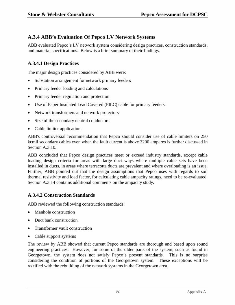
Stone & Webster Consultants Pepco Assessment for DCPSC
Appendix A92
A.3.4 ABB’s Evaluation Of Pepco LV Network Systems
ABB evaluated Pepco’s LV network system considering design practices, construction standards,and material specifications. Below is a brief summary of their findings.
A.3.4.1 Design Practices
The major design practices considered by ABB were:
• Substation arrangement for network primary feeders
• Primary feeder loading and calculations
• Primary feeder regulation and protection
• Use of Paper Insulated Lead Covered (PILC) cable for primary feeders
• Network transformers and network protectors
• Size of the secondary neutral conductors
• Cable limiter application.
ABB's controversial recommendation that Pepco should consider use of cable limiters on 250kcmil secondary cables even when the fault current is above 3200 amperes is further discussed inSection A.3.10.
ABB concluded that Pepco design practices meet or exceed industry standards, except cableloading design criteria for areas with large duct ways where multiple cable sets have beeninstalled in ducts, in areas where terracotta ducts are prevalent and where overloading is an issue.Further, ABB pointed out that the design assumptions that Pepco uses with regards to soilthermal resistivity and load factor, for calculating cable ampacity ratings, need to be re-evaluated.Section A.3.14 contains additional comments on the ampacity study.
A.3.4.2 Construction Standards
ABB reviewed the following construction standards:
• Manhole construction
• Duct bank construction
• Transformer vault construction
• Cable support systems
The review by ABB showed that current Pepco standards are thorough and based upon soundengineering practices. However, for some of the older parts of the system, such as found inGeorgetown, the system does not satisfy Pepco’s present standards. This is no surpriseconsidering the condition of portions of the Georgetown system. These exceptions will berectified with the rebuilding of the network systems in the Georgetown area.

Stone & Webster Consultants Pepco Assessment for DCPSC
Appendix A93
A.3.4.3 Material Specifications
ABB reviewed the following material specifications:
• Network protectors
• Network transformers
• Cable limiters
• Primary feeder cables
• Secondary network cables
• Arc resistant tapes
ABB concludes that Pepco material specifications are consistent with those of other low-voltagenetwork operators.
ABB concludes that failures of splices in paper insulated lead covered cables (PILC) representthe highest incident rate of contributing causes for manhole events. However, they did notidentify measures that Pepco might take to reduce the number of failures in splices made onPILC cables.
ABB recommend that Pepco evaluate changes in material specifications that might reduce thenumber of splice failures, such as using EPR insulated primary cables with pre-molded splices asan alternative to the PILC primary cables.
A.3.4.4 Advanced Diagnostics Testing of Primary Feeders
Attachment #11 to the ABB report lists several diagnostics testing methods for distributionfeeders. Other methods than the ones listed may also be available. All of the methods arerelatively new and the interpretation of the test results requires a high level of technical skill andextended experience with each test method. Therefore the value of the diagnostic testing needsto be examined closely to verify that the test results can be correctly interpreted, and the resultscan be implemented in a cost-effective manner.
None of the methods being utilized by the electric utility industry has reached a state ofconfidence that would suggest developing a diagnostics testing program for the distributionfeeders at the Pepco system. Pepco should continue to monitor the progress being made onexisting and new diagnostics testing methods.
A.3.5 Superior Aspects of Pepco’s LV Network Systems
In four important areas, the designs of Pepco’s low-voltage network systems are superior to thoseof many system operators. Three of these areas are alluded to in the ABB report, but the fourth isnot mentioned at all. Those evaluating and judging Pepco’s low-voltage network system shouldbe cognizant of these aspects.

Stone & Webster Consultants Pepco Assessment for DCPSC
Appendix A94
A.3.5.1 Low-voltage Network Size
Each of Pepco’s low-voltage networks has six 13,800-Volt (13 kV) high-voltage feeders. In anynetwork, any one high-voltage feeder can be removed from service, and the remaining fivefeeders can supply the peak load. This is referred to as single contingency design. See SectionA.3.9 for a description of the low-voltage network system and its topology.
Pepco limits the size of each low-voltage network to the range of 30,000,000 to 45,000,000 Volt-Amperes (30 MVA to 45 MVA). These numbers give an indication of the peak power that canbe supplied from a given low-voltage network. In terms of mechanical power, each network cansupply a load in the range of 30,000 to 45,000 horsepower. With the size of each networklimited to 45 MVA, the maximum load that could be dropped upon a catastrophe in a single low-voltage network system is 45 MVA. In comparison, there are low-voltage secondary networksoperating in other large metropolitan areas where the load on a given network is in the range of100 to 200 MVA or larger, and the number of high-voltage feeders is much larger than six. Forthese systems, a catastrophe necessitating a network shutdown drops a much larger block of load,affecting a greater number of customers. Furthermore, the larger the network, the more difficultit is to restore the network to operation following complete shutdown from a major catastrophe.
A.3.5.2 Substation Bus Configuration
For each low-voltage network, there are six high-voltage feeders. Pepco distribution substationsthat supply the network’s 13,800-volt high-voltage primary feeders have a ring bus configurationwith at least six sections. Each feeder connects to a different section of the ring bus, as shown inthe simplified system in Figure A.3-3 in Section A.3.9, except that the simplified system has justthree feeders, and there are just three sections to the ring bus.
With the ring bus arrangement, a fault on any one section of the ring bus will result in the loss ofonly one high-voltage primary feeder to the network. This single contingency condition does notresult in customer outages since the low-voltage network is designed to carry the peak load withany one of the six high-voltage primary feeders out of service. In comparison, a fault on thesubstation bus in some network systems will result in the loss of two high-voltage feeders to thenetwork, which may result in dropping of the entire network.

Stone & Webster Consultants Pepco Assessment for DCPSC
Appendix A95
A.3.5.3 One Network Unit Per VaultPepco installs only one network unit (network transformer and network protector) in below gradevaults. When there are two or more network units in separate vaults at the same location, thisgreatly reduces the probability of a disturbance in one network unit propagating to anothernetwork unit, or the primary feeder cables supplying the other network unit. As illustrated inFigure A.3-1, each of the three network units for a spot network is in a separate vault. Inaddition, the paralleling bus for the spot network is in a separate vault, referred to as a bus hole.
Should a fault occur in the high-voltage disconnect and grounding switch of one of the networkunits, the compartment may rupture and an oil fire may ensue. With each unit being in a separatevault, it is very unlikely that the fault will propagate to another network unit or to anotherprimary feeder in a separate vault, or to the paralleling bus in the bus hole.
In contrast, some utilities will locate all of the network units and the paralleling bus in the samevault, exposing multiple primary feeders and unfaulted equipment to the effects of a disruptivefailure of liquid filled apparatus.
DISK #3PSCDCNWK2.FCW
NWP. 1
NETWORKXFR.
1
HV. FDR. 1
TRANSFORMERVAULT 1
NWP. 2
NETWORKXFR.
2
HV. FDR. 2
TRANSFORMERVAULT 2
NWP. 3
NETWORKXFR.
3
HV. FDR. 3
TRANSFORMERVAULT 3
BUS HOLE
PARALLELINGBUS
CUSTOMER LOADS
VAULT WALLS
BUS HOLE WALLS
HV. FDR. HIGH VOLTAGE FEEDERHV. SW. HIGH VOLTAGE DISCONNECT AND GROUNDING SWITCHXFR. TRANSFORMERNWP. NETWORK PROTECTOR
ABBREVIATIONS
HV. SW. 1 HV. SW. 2 HV. SW. 3
Figure A.3-1 Three-unit Spot Network Where Each Network Unit and the Paralleling BusAre In Separate Vaults
A.3.5.4 Relays
Pepco, on the 13 kV feeders that serve just network transformers, referred to as dedicatednetwork feeders, installs phase instantaneous current relays and ground instantaneous currentrelays. These are the relays that will detect a fault in a high-voltage feeder cable, in a splice in aPILC cable, a fault in the terminal compartment or in the disconnect switch of a network
Stone & Webster Consultants Pepco Assessment for DCPSC
Appendix A96
transformer, or a fault within the transformer itself (see Figure A.3-1). When the fault is detectedwith these relays, the circuit breaker at the distribution substation is opened to interrupt the flowof fault current.
By necessity, the pickup of the phase instantaneous current relay must be high so that it will notrespond to faults in the low-voltage portion of the systems. The pickup of the groundinstantaneous current relay, with network transformer configured as purchased by Pepco (deltaconnected high-voltage winding), can be set much lower than the phase instantaneous currentrelay. The lower the pickup setting, the more sensitive the protection for ground faults in theprimary (13 kV) winding of the network transformer and for faults in splices.
Data submitted by Pepco in response to Stone and Webster data request 5 show that Pepco setsthe pickup of the ground instantaneous current relay lower than most other utilities. Althoughthe Pepco setting varies from substation to substation, most ground instantaneous current settingsdo not exceed 300 to 400 amperes, and in some cases they are much lower than this. This meansthat ground faults will be detected instantaneously, and cleared from the substation end in theshortest possible time when conventional circuit interrupting devices are used. Sensitive settingsand the associated short clearing times are important as they minimize the chance of a groundfault in a network transformer primary winding resulting in rupture of the transformer tank andthe associated oil fire. In comparison, the minimum settings used by some operators are three tofour times higher than the minimum setting used by Pepco.
However, even with the sensitive ground relay setting, a ground fault in the high-voltage terminalcompartment or switch compartment of a network transformer usually will result in the ruptureof the compartment and an oil fire, due to the clearing time of the circuit breaker at thesubstation. However, there are means of further reducing the clearing time for such faults, aswell as for faults in the splices of PILC cables, as discussed in Section A.3.7.
A.3.6 Evaluation of ABB Recommendations
The ABB study contains 14 recommendations to Pepco. Adoption of these recommendations byPepco will enhance the overall reliability and security of the network systems, as well as reducethe probability of manhole explosions. In response to Commission Order No. 12036, Pepco hasprovided an implementation chart to the Commission indicating the extent to which it willimplement the ABB recommendations.
For the most part, Pepco is implementing the recommendations made by ABB. However, someof the recommendations made by ABB would be subject to debate by operators of low-voltagenetwork systems. As a result, in these cases Pepco has indicated that they are continuing toinvestigate the recommendation and its applicability to the Pepco systems. This is theappropriate response when there are considerable differences of opinion amongst practitionerswho are knowledgeable with the issue.
For example, Pepco is continuing to evaluate the ABB recommendations with regards to theapplication of cable limiters in the low-voltage network system, and with regards to increasingfault currents to help faults burn clear or blow cable limiters, when installed.

Stone & Webster Consultants Pepco Assessment for DCPSC
Appendix A97
A.3.7 Areas Not Considered In The ABB Study and AdditionalRecommendations
A.3.7.1 Current-Limiting Devices and Phase Reactors
The sections of the ABB Report dealing with Engineering Design Practices failed to investigatetwo practices that might have an impact on manhole explosions (lid blowings) for faults insplices of PILC cables for the network primary feeders operating at 13 kV. These may also havean impact on the rupturing of cable terminal compartments, and the rupturing of switchcompartments on network transformers for faults in these compartments.
The first involves the installation of phase reactors on the primary feeders of the low-voltagenetworks. This will not reduce the time required to isolate a fault in a splice from the source atthe distribution substation. However, it will reduce the available short circuit current, and it willreduce the energy into the splice at the point of fault. Regardless of the available short circuitcurrent on the primary feeder of the Pepco system, the fastest clearing time from the substationend will be 5 cycles (0.0833 seconds).
The second involves the application of current-limiting devices on the primary feeder at thesubstation. The current-limiting device, in effect, performs the same function as the phaseinstantaneous current relays presently installed in the Pepco system. However, high-currentfaults in cable splices and network transformers would be interrupted from the substation side inless than 1 cycle, in comparison to 5 cycles as in the present system. Furthermore, with thecurrent-limiting devices, the magnitude of the current flowing into the fault will be reduced. Thenet effect of this is that the energy into the fault in a splice, or into the fault in a cablecompartment or switch compartment in a network transformer can be reduced by a factor of 10 ormore, depending on particulars.
These current-limiting devices have been installed by just one utility in the USA in their networksystems. This is the Tampa Electric Company. They report that this device is very effective inpreventing manhole cover displacements from faults in primary cables. It also has been veryeffective in preventing the rupture of terminal compartments and switch compartments on thehigh-voltage side of network transformers. A description of the installations and theeffectiveness on the Tampa Electric system is contained in the Electrical World Magazine article,“Electronic Fuses Protect Cable, Network Transformers”, the January 1994 edition.
The application of current-limiting devices is discussed further in Section A.3.11.
Stone & Webster Recommendation No. 1
Pepco should evaluate the applicability of current-limiting devices to its system. Although Pepcodoes not install phase reactors on their primary feeders supplying the low-voltage networks, suchdevices are installed on distribution circuits fed from some substations that also supply networks.Pepco should also evaluate their existing databases to determine if installation of just phasereactors on network primary feeders would have a significant impact on manhole explosions forfaults in primary cable splices, due to the reduction of available fault current. These reactors willalso reduce heating in cable sheaths and splices for most ground faults.

Stone & Webster Consultants Pepco Assessment for DCPSC
Appendix A98
A.3.7.2 Fault Location Time in Network Systems
Each of Pepco’s low-voltage networks has six 13,800 volt primary feeder circuits. When a faultoccurs on any one primary feeder circuit, it is automatically isolated, and the remaining fiveprimary feeders carry the load of the network. When this happens, the load on the remaining fivefeeders will increase about 20% or more, depending on the interlacing of the feeders and the loaddistribution. The corresponding I2R losses and heating on some primary feeder cables will go upby at least 44%. Furthermore, in the 208-volt grid network the loading on secondary cables willincrease.
Operating at higher loading levels increases the likelihood of a failure occurring in a secondcomponent of the system, and in turn causing a manhole event or an outage.
It is therefore important that faults on network high-voltage primary feeders are rapidly located,repaired, and the high-voltage primary feeder place back into service as soon as possible. Atpresent, Pepco uses sheath coils to pre-locate faults on primary feeders, and picks to pinpoint thefault location on feeders with PILC cable. This can be a time consuming process, as it requiresopening manholes so that personnel can enter to make measurements. If a manhole is flooded,additional delays are incurred until the water is removed.
Stone & Webster Recommendation No. 2
Pepco should evaluate some of the newer technologies and equipment recently developed forlocating faults on network primary feeder circuits. These were developed for the ConsolidatedEdison Company of New York, the operator of the largest low-voltage network systems in theworld. The particular device that Con Edison is presently using is the “above ground” meter,which allows pre-location of the fault without the need to open and enter manholes. The devicewas originally developed by AT&T Bell Laboratories, and is now available in commercial formfrom the Technology Enhancement Corporation. The operator of the above ground meter needonly travel the route of the primary feeder to locate the fault, without need to enter manholes.
In addition, Pepco is encouraged to monitor the progress being made on real-time fault locationschemes being developed for Con Edison. With these schemes, the objective is to have a systemthat will tell system operators, almost instantaneously after feeder breaker opening, the distanceof the fault from the substation or some other reference point. When such devices or systemsbecome available, Pepco is encouraged to evaluate their applicability to the Pepco low-voltagenetwork systems.
A.3.7.3 Network Relay Close Characteristics
Section 7.1 of the ABB report reviews the settings used by Pepco for their network protectorrelays, and concludes that, “Pepco’s settings as summarized in Table 1, are typical settings foundamong many network utilities. No changes to these settings are recommended at this time.” Weare in complete agreement with this.
However, the newer microprocessor relays available today have both the conventional straight-line master close characteristic and the straight-line phasing close characteristic, as well as thenewly developed circular close characteristic. The user selects the type of close characteristicand settings. For isolated spot networks fed from dedicated primary feeders, the use of thecircular close characteristic will allow an open protector to automatically reclose at a lower loadon the network, without unduly increasing the number of protector operations. The net effect of

Stone & Webster Consultants Pepco Assessment for DCPSC
Appendix A99
this is to have all protectors in the spot network closed over a greater period of the time. This inturn enhances the reliability of the system, especially in two-unit isolated spot networks. Pepcohas spot networks fed from dedicated primary feeder circuits, emanating from the samesubstation.
Section A.3.12 contains a discussion of the straight-line and circular close characteristics ofnetwork relays used in low-voltage network protectors.
Stone & Webster Recommendation No. 3
Pepco is encouraged to consider the application of the circular close characteristics in each spotnetwork whenever the microprocessor relays are incorporated into all protectors in the spotnetwork.
A.3.8 Technical Critique
As indicated earlier in this report, the ABB study is very thorough and complete in its evaluationof Pepco with regards to System Analysis, Engineering Design Practices, and Diagnostic andCondition Assessment. The main exception is the failure to include recommendations toevaluate the applicability and effectiveness of current-limiting devices for the protection ofprimary feeders, and as a means of reducing manhole explosions.
Furthermore, several technical inaccuracies appear in the ABB report. They are discussed inSection A.3.13. It is emphasized, however, that these inaccuracies do not impact the findingsand recommendations of the ABB report.
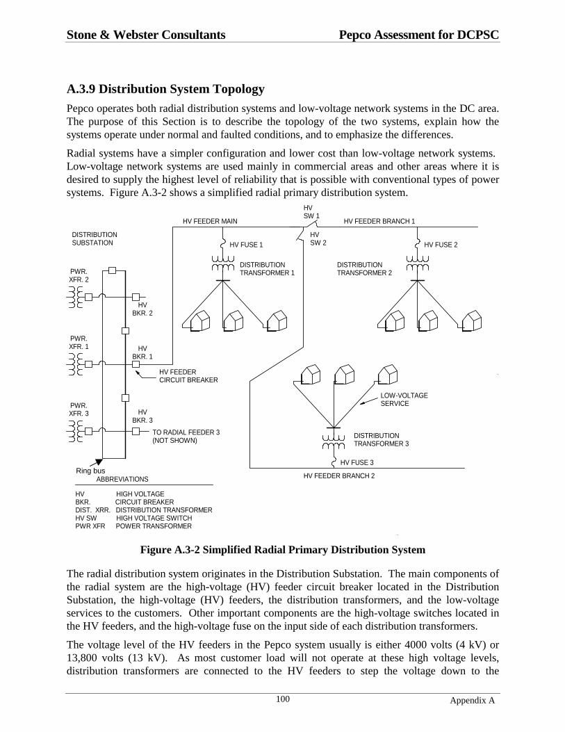
Stone & Webster Consultants Pepco Assessment for DCPSC
Appendix A100
A.3.9 Distribution System Topology
Pepco operates both radial distribution systems and low-voltage network systems in the DC area.The purpose of this Section is to describe the topology of the two systems, explain how thesystems operate under normal and faulted conditions, and to emphasize the differences.
Radial systems have a simpler configuration and lower cost than low-voltage network systems. Low-voltage network systems are used mainly in commercial areas and other areas where it isdesired to supply the highest level of reliability that is possible with conventional types of powersystems. Figure A.3-2 shows a simplified radial primary distribution system.
LOW-VOLTAGESERVICE
DISTRIBUTIONSUBSTATION
HV FEEDER CIRCUIT BREAKER
DISK #3PSCDCRADIAL1.FCW
HVBKR. 2
HVBKR. 1
HVBKR. 3
HV HIGH VOLTAGEBKR. CIRCUIT BREAKERDIST. XRR. DISTRIBUTION TRANSFORMERHV SW HIGH VOLTAGE SWITCHPWR XFR POWER TRANSFORMER
ABBREVIATIONS
DISTRIBUTIONTRANSFORMER 1
DISTRIBUTIONTRANSFORMER 2
DISTRIBUTIONTRANSFORMER 3
HVSW 1
HVSW 2HV FUSE 1 HV FUSE 2
HV FUSE 3
TO RADIAL FEEDER 3(NOT SHOWN)
HV FEEDER MAIN HV FEEDER BRANCH 1
HV FEEDER BRANCH 2
PWR.XFR. 2
PWR.XFR. 1
PWR.XFR. 3
Figure A.3-2 Simplified Radial Primary Distribution System
The radial distribution system originates in the Distribution Substation. The main components ofthe radial system are the high-voltage (HV) feeder circuit breaker located in the DistributionSubstation, the high-voltage (HV) feeders, the distribution transformers, and the low-voltageservices to the customers. Other important components are the high-voltage switches located inthe HV feeders, and the high-voltage fuse on the input side of each distribution transformers.
The voltage level of the HV feeders in the Pepco system usually is either 4000 volts (4 kV) or13,800 volts (13 kV). As most customer load will not operate at these high voltage levels,distribution transformers are connected to the HV feeders to step the voltage down to the
Ring bus

Stone & Webster Consultants Pepco Assessment for DCPSC
Appendix A101
utilization level, the voltage levels at which consumer equipment operates. This might be thefamiliar 120 volts found in residences, although other utilization voltage levels are used forcommercial and industrial applications. Low-voltage secondary circuits and low-voltage servicescarry the power from the distribution transformer to the customer’s premises.
The simplified system of Figure A.3-2 shows only one radial HV feeder emanating from thedistribution substation. In an actual system, there would be many such feeders emanating fromthe substation, going in different directions to supply the loads.
The power flow in each component is always away from the distribution substation under normal(unfaulted) conditions in the radial system. The topology of the radial system is similar to that ofa tree with the roots being the substation bus. The HV feeder main corresponds to the tree’strunk, the HV feeder branches correspond to the tree branches connected to the tree’s trunk, thedistribution transformers correspond to second-level branches of the tree, and the low-voltageservices correspond to third-level branches of the tree. As long as there are no interruptions inany of the paths of the radial distribution system, power will flow from the distribution substationto all customers fed from the system. This is analogous to nutrients flowing from the earth to thetree’s leaves as long as the trunk and none of the branches are completely severed.
Should a short circuit (fault) occur on the HV feeder main, or one of the HV feeder branches,very high electric currents flow from the substation to the point where the short circuit exists. Ifthese high currents were allowed to flow uninterrupted, the conductors of the HV feederscarrying the current would overheat, and could melt and fuse, causing massive damage. Toprevent this, relays are installed at the distribution substation to detect these high currents. Therelays initiate opening of the HV feeder breaker at the substation, which interrupts the flow ofshort circuit current and prevents further energy input and damage to the system. In interruptingand isolating the short circuit on the HV feeder in this fashion, all customers supplied from theradial feeder experience a loss of power.
All customers in Figure A.3-2 will be out of service until the fault can be located. After the faultis located, all or a portion of the customers will still be without service until the fault can berepaired and the feeder re-energized. If the fault were on the HV feeder main in Figure A.3-2, allcustomers are without service until the fault is located and repaired.
If the fault were on HV feeder branch 1 in Figure A.3-2, all customers are without service untilthe fault is located. After the fault is located, high-voltage switch 1 (HV SW 1) can be opened toisolate the faulted section of the HV feeder. Then the HV circuit breaker at the substation isclosed to energize the HV main feeder and HV feeder branch 2. This restores electric service toall customers supplied from the transformers connected to these portions of the radial circuit. After the fault is repaired, service can be restored to the customers supplied from HV feederbranch 1 by the closing of high-voltage (HV) switch 1.
What should be clear from the proceeding is that when faults occur in radial HV systems, a largenumber of customers can be affected, and the length of the power outage can be quite long. Thisis especially true in radial distribution systems that are located below ground, because it may bedifficult and time consuming to locate the fault. However, Pepco does install faulted circuitindicators in 13 kV radial systems, to reduce the time required to locate faults. The 13 kV radialcircuits also have a loop configuration, which allows service restoration, in many cases, withoutneed to repair the fault.

Stone & Webster Consultants Pepco Assessment for DCPSC
Appendix A102
Low-voltage secondary network systems were developed in the 20’s to provide highly reliableservice to commercial areas of cities and towns.
Figure A.3-3 shows a simplified low-voltage secondary network system that serves the sameloads as the radial system in Figure A.3-2. As will be seen from the following discussion, a shortcircuit on a high-voltage feeder circuit, in a network transformer, and in a low-voltage secondarymain does not cause a loss of power to the customers.
NWK. XFR. 1
NWP. 1
NWK. XFR. 2
NWP. 2
NWK. XFR. 3
NWP. 3
CABLE LIMITER
HV FEEDER 1
HV FEEDER 2
HV FEEDER 3
LOW-VOLTAGESERVICE
DISTRIBUTIONSUBSTATION
HV FEEDER CIRCUIT BREAKER
DISK #3PSCDCNWK1.FCW
HVBKR. 2
HVBKR. 1
HVBKR. 3
HV HIGH VOLTAGEBKR. CIRCUIT BREAKERNWK. XRR. NETWORK TRANSFORMERNWP. NETWORK PROTECTORPWR. XFR. POWER TRANSFORMER
ABBREVIATIONS
LOW-VOLTAGESECONDARY MAIN 1-3
LOW-VOLTAGE SECONDARY MAIN 1-2
LOW-VOLTAGESECONDARY MAIN 2-3
PWR.XFR. 2
PWR.XFR. 1
PWR.XFR. 3
LV BUS 1 LV BUS 2
LV BUS 3
Figure A.3-3 Simplified Low-Voltage Secondary Network System
The low-voltage network system originates at the Distribution Substation in Figure A.3-3. Themain components of the low-voltage network system are the high-voltage feeder circuit breakerslocated at the Distribution Substation, the high-voltage (HV) feeders, and the network units(consisting of a network transformer and a network protector). Each network unit feeds a low-voltage (LV) bus adjacent to each network unit. Low-voltage secondary mains connect the low-voltage buses at different locations in the load area. Low-voltage services to the customers arefed from the low-voltage buses. Sometimes, customers are fed directly from taps to the low-voltage secondary mains, although this is not shown in Figure A.3-3.
In the simplified system of Figure A.3-3, there are three high-voltage feeders with just onenetwork unit fed from each high-voltage feeder. Each of Pepco’s 47 networks has 6 high-voltagefeeders supplying it, with there being a multiplicity of network units fed from each high-voltagefeeder. The voltage level of the high-voltage feeders in the Pepco system is 13 kV.
Ring bus

Stone & Webster Consultants Pepco Assessment for DCPSC
Appendix A103
The low-voltage network (low-voltage buses and low-voltage secondary mains in Figure A.3-3)is a three-phase system which supplies both three-phase power load, such as motors for airconditioning and elevators, and single-phase lighting load (such as lighting, computers, oranything that is plugged into a wall receptacle). The voltage level of the low-voltage networkfrom which the load is served is either 208 volts, or 480 volts depending on the requirements ofthe customer.
Under normal conditions in the low-voltage network system of Figure A.3-3, the power flow ineach HV feeder is from the distribution substation to the network unit (network transformer andprotector). In each network unit the power flow is from the network unit to the low-voltagebuses, and along the secondary mains. There is more than one path for the power to flow fromthe distribution substation to any one customer. The system is protected such that if a shortcircuit (fault) occurs in any one path, the short circuit is automatically isolated without causing aninterruption to the customers served from the network.
Consider a short circuit on high-voltage feeder 1 in Figure A.3-3. When this occurs, highcurrents flow in HV feeder 1 from the distribution substation to the short circuit. Relays detectthis high current and open high-voltage (HV) breaker 1 located in the substation. After HVbreaker 1 at the distribution substation automatically opens, there is a reverse power flow innetwork protector 1 (NWP 1), and it automatically opens. The automatic opening of HV breaker1 and NWP 1 isolates the fault on HV feeder 1. Although this disconnects network unit 1 fromlow-voltage bus 1 (LV bus 1), the loads on LV Bus 1 are supplied through low-voltage secondarymain 1-2 and low-voltage secondary main 1-3, and do not experience an outage.
From Figure A.3-3, no matter which high-voltage feeder has the short circuit, all customersserved from the low-voltage network will not experience an outage. The system is designed sothat with any one HV feeder and its associated network transformers removed from service, theremaining parts of the system can carry the peak load. This is referred to as single-contingencydesign.
A short circuit in a network transformer is automatically isolated in the same fashion as a shortcircuit on the HV feeder, and customers supplied from the low-voltage network will notexperience an outage. A HV feeder of the network can be removed from service for inspection,maintenance, testing, or repair, and customers supplied from the network do not experience anoutage.
Pepco also designs their low-voltage network systems such that if a short circuit occurs on anyone bus section in the Distribution Substation in Figure A.3-3, or if there is a failure of any onemain power transformer (PWR. XFR) in Figure A.3-3, no customer will experience an outage.
If a short circuit occurs on a 208-volt low-voltage secondary main, it will either burn clear or beisolated by the cable limiters at each end of the secondary mains. This also will not result in anoutage to any customers served from the low-voltage buses. However, if there are customerstapped directly from the secondary main which has the short circuit, the customers on the shortedsecondary main will loose power until repairs can be made. Section A.3.10 gives a brief historybehind the cable limiter, and a description of its basic functions.
Should a short circuit occur on a low-voltage bus in Figure A.3-3, then those customers suppliedfrom the bus with the short circuit will experience an outage.
From the preceding discussion of the response of the low-voltage network system, it is clear thatmost short circuits in the system do not cause power outages to the customers supplied from the
Stone & Webster Consultants Pepco Assessment for DCPSC
Appendix A104
network. This is why the low-voltage network system offers the highest levels of reliabilitypossible with conventional power systems, and is used extensively in many metropolitan areas. Data supplied by Pepco to the Commission confirms this fact.

Stone & Webster Consultants Pepco Assessment for DCPSC
Appendix A105
A.3.10 Cable Limiters
Pepco operates a 208-volt low-voltage network system. In the Executive Summary of the ABBreport, it is stated that, “Pepco’s cable limiter application exceeds industry standards.” There areno industry standards on the application of cable limiters to low-voltage secondary networks, butthere are practices. Pepco has guidelines for limiter application in 250 kcmil low-voltage cablesin the 208-volt networks. Limiters are not installed with a single set of cables installed in a ductif the fault current in-feed from both sides of a fault on the set of cables is 3200 amperes orhigher. Limiters are installed at both ends of 250 kcmil cables only when there are two or moresets installed in a duct, irrespective of the available fault current. ABB recommends that Pepcoconsider applying limiters on both ends of 250 kcmil cables when there is just a single set in aduct, irrespective of the in-feed current on both sides of the fault.
Cable limiters were not used in the early low-voltage secondary network systems, and todaysome utilities still do not use cable limiters. Figure A.3-4 shows a portion of a low-voltagenetwork system where cable limiters are not used. In comparison, some utilities install cablelimiters on all secondary cables, including 250 kcmil copper cables as used by Pepco,irrespective of the available fault current and the number of sets of cable in a duct. In the Pepco208-volt secondary systems, cable limiters are installed in some 208-volt secondary circuits. InPepco’s 480-volt secondary system, cable limiters are installed in all low-voltage cable circuits,irrespective of cable size or available fault current.
SEC. MAINS NORTH
SEC. MAINS SOUTH
EACH LINE REPRESENTS 3 PHASES AND NEUTRAL IN DUCT (PHASE GROUPED)
X
LOAD
VAULT 2500 KVA
VAULT 1500 KVA
VAULT 3750 KVA
SEC. MAINS NORTH
SEC. MAINS SOUTH
LOAD
FAULT 1
DCPSC03.FCWDISK # 1
BUS HOLE 1 BUS HOLE 2
NWP FUSE
Figure A.3-4 A Portion of a Low-Voltage Network System without Cable Limiters

Stone & Webster Consultants Pepco Assessment for DCPSC
Appendix A106
In 208-volt systems without cable limiters, the intent that was that the short circuit in the cableswould burn clear at the fault point at the low-voltages involved (either 120 volts or 208 volts). The burn clear philosophy was based upon tests conducted in the late 20’s and reported in apaper presented in 1931 titled, “Burn-Off Characteristics of AC Low-Voltage Network Cables.” In these tests, two insulated cables in duct had the insulation stripped from about a 3-inchsegment, and the bare conductors were held in contact with tape. Then the circuit was energizedto determine how much in-feed current was required on both sides of the fault to burn clearwithout the fault spreading. In order for burn clear to occur, the I2R heating at the contact pointbetween the two faulted conductors must produce sufficient temperature rise to melt the copperconductors at the contact point. Yet, at the same time the in-feed current on either side of thefault must not elevate the temperature of the conductor remote from the fault point such that thecable insulation is damaged, thereby allowing the fault to spread. From tests and calculations, itwas determined that burn clear would occur as long as the in-feed on both sides of the faultexceeded 3200 amperes for the 250 kcmil cables.
The burn clear philosophy further assumed that after burn through occurred at the point of fault, aphysical separation would occur between the conductors at different voltage, and that the voltagebetween the two conductors would not be sufficient to cause a re-ignition of the fault. Even ifburn clear occurs and a physical separation is maintained between the faulted conductors, avoltage difference is maintained at the fault point, as the cables are energized from bus hole 1and bus hole 2. This voltage could be either 208 volts, or 120 volts depending on which cableswere involved in the fault.
As the utility industry gained experience with low-voltage networks, it was found that faults didnot always burn clear in the 208-volt system, and the fault could propagate to other portions ofthe low-voltage cable grid by melting the insulation of the cable remote from the fault point. Even if the fault did burn clear, the cables on both sides of the fault would remain energized, andthe fault could re ignite at a later time due to electrical tracking from contaminants in the duct. Inthe simplified system of Figure A.3-4, if the fault does not burn clear and propagates back to thebus hole, cables from other low-voltage circuits may become involved. Furthermore, the longerthe fault takes to burn clear, the more gases are generated from the cable insulation as it isdecomposed.
The cable limiter was developed in the thirties to prevent faults that don’t burn clear fromspreading or propagating to other portions of the network. A cable limiter is basically a fuseinstalled at both ends of each cable. It was called a cable limiter because its purpose was to limitthe damage to the cable insulation at points remote from the point of fault. Of course, the cablelimiter also will de-energize the cable after it opens. For currents above a predetermined level,the cable limiter will melt and interrupt the fault current before the cable insulation is damaged. However, for very low fault currents, the exact level dependant upon cable size and thermalcharacteristics of the cable circuit and duct bank, the limiter may not melt before the cableinsulation reaches the damage level of 260 degrees C.

Stone & Webster Consultants Pepco Assessment for DCPSC
Appendix A107
Figure A.3-5 shows the same system as in Figure A.3-4, except that cable limiters are installed atboth ends of each low-voltage cable. The cable limiter was designed such that for a fault thelimiters at both ends of the faulted cable circuit would melt and clear the fault before thetemperature of the copper conductor, remote from the fault point, would reach the level where itwould melt the cable insulation. When the cable limiter opens to de-energize the fault, it willremove voltage from the fault, thereby minimizing the probability that the fault will re-ignite. Ifthe cable insulation remote from the fault point melts, the fault may spread, just as when limitersare not used.
When cable limiters are installed in all low-voltage circuits as shown in Figure A.3-5, the cablelimiters must be coordinated such that the only limiters that blow are those at both ends of thefaulted cable circuit. For Fault 1, the only limiters that should blow are those labeled L1 and L2.With a multiplicity of cables as in Figure A.3-5, selective coordination of limiters usually ispossible.
Even when cable limiters are installed, it is not guaranteed that the limiters will clear all faultsbefore fires ensue. If the fault currents are low, regardless of the reason, the fault may producedamage at the fault point that decomposes the insulation and causes fires in the manholes andducts before the limiters blow. Manhole fires and explosions have occurred in systems that havecable limiters, but the probability of this happening in a system with limiters is lower than insystems without cable limiters.
SEC. MAINS NORTH
SEC. MAINS SOUTH
EACH LINE REPRESENTS 3 PHASES AND NEUTRAL IN DUCT (PHASE GROUPED)
L1
L2
X
LOAD
VAULT 2500 KVA
VAULT 1500 KVA
VAULT 3750 KVA
SEC. MAINS NORTH
SEC. MAINS SOUTH
LOAD
FAULT 1
DCPSC01.FCWDISK # 1
BUS HOLE 1 BUS HOLE 2
CABLE LIMITER
NWP FUSE
Figure A.3-5 Portion of Low-Voltage Network System with Cable Limiters Installed atBoth Ends of Every Cable

Stone & Webster Consultants Pepco Assessment for DCPSC
Appendix A108
Figure A.3-6 shows the same system except that cable limiters are installed in selective low-voltage cable circuits, similar to the practices on some utilities, including Pepco. Pepco installslimiters in all 500 kcmil cables, but not in 250 kcmil cables when there is just one set in a duct.
For faults on cable circuits without limiters, the intent of the design is that the fault burns clear,not only before the fault causes damage to the insulation of the faulted cable remote from thefault point, but before limiters on other “unfaulted” cables can melt. If cable limiters onunfaulted low-voltage circuits melt before the fault burns clear, it may destroy the integrity of thelow-voltage network system.
When cable limiters are installed in all cable circuits as in Figure A.3-5, it is possible todetermine if the limiters at both ends of the faulted cable will isolate the fault before limiters onany of the unfaulted cables can blow. This is possible because there are curves showing the timefor the cable limiter to melt as a function of the current in the limiter. These curves are calledtime-current curves. By knowing the current in each limiter around the fault point, and havingthe limiter time-current curves, the coordination between cable limiters can be evaluated.
When cable limiters are not installed in all cables as in Figure A.3-6, the evaluation ofcoordination is more difficult. The reason for this is that there are no data sources giving thetime for a cable fault to burn clear as a function of current. For example, for Fault 1, there willbe significant current in the secondary mains with limiters, and in the cables with limitersbetween the transformer vaults and the bus holes. The limiter melting times are known, but thereis uncertainty about the self-clearing time of the fault in the cable without limiters.
ABB has recommended that Pepco consider evaluating if limiters should be installed in all 250kcmil cable circuits, irrespective of the available fault current levels.
SEC. MAINS NORTH
SEC. MAINS SOUTH
EACH LINE REPRESENTS 3 PHASES AND NEUTRAL IN DUCT (PHASE GROUPED)
X
LOAD
VAULT 2500 KVA
VAULT 1500 KVA
VAULT 3750 KVA
SEC. MAINS NORTH
SEC. MAINS SOUTH
LOAD
FAULT 1
DCPSC02.FCWDISK # 1
BUS HOLE 1 BUS HOLE 2NWP FUSE
CABLE LIMITER
XFAULT 2
Figure A.3-6 Portion of Low-Voltage Secondary Network System with Limiters Installed inSome of the Low-Voltage Cable Circuits

Stone & Webster Consultants Pepco Assessment for DCPSC
Appendix A109
A.3.11 Fault Current-Limiting Devices
More faults occur on the primary feeders of secondary networks than in the low-voltage cables. This statement is supported by data from Pepco and other utilities participating in the survey. Further, faults in primary cable splices have resulted in ejection of manhole covers. In thesystem of another utility (not Pepco), the ejection of a manhole cover from a fault in a cablesplice on a primary feeder resulted in a fatality to an occupant of a motor vehicle when themanhole cover passed through the windshield.
Researchers suggest that the high pressures ejecting manhole covers may be caused by twoseparate mechanisms for faults in the splices of PILC cables. One is the ignition of gasesgenerated when the splice insulating materials become decomposed from heating due to tracking. The other is from the heating of air and volatilization of conductor material during the ensuinghigh-current arc.
In the first mechanism, tracking of splice fill-materials creates heat. The heat generates gasesthat are explosive, and softens the lead splice. Then if the lead splice ruptures due to internalpressures from the generated gasses, and there is a spark or arc, the gasses generated from thedegradation of the splice may explode. If the pressures produced by ignition of the volume ofgases generated from the tracking are, by themselves, sufficient to eject a manhole cover, thenthe use of current-limiting devices probably would not be effective in preventing manhole coverejections from faults in cable splices.
However, if the manhole lid ejects due to high ampere fault current of the arc, then current-limiting devices may prevent manhole lid ejections.
When a fault path develops in a splice of a high-voltage cable, the resulting power arc has veryhigh currents that flow from the substation to the fault until the circuit breaker at the substationopens. Even after the station circuit breaker opens, fault currents may continue to flow in thefault until all backfeeding network protectors open. The backfeed current typically will be oflower magnitude than that coming directly from the substation. With reference to Figure A.3-3,currents flow into a fault on the high-voltage feeder cable from both the distribution substationand the backfeeding network protectors.
The energy input to the fault is the time integral of the arc voltage and the arc current. Anychanges in system design or protection that reduce the magnitude of the available fault current,and any changes that reduce the time that the current flows will reduce the energy into the fault,and the pressures generated in the manhole.
Figure A.3-7 shows with the heavy curve the current flow from the substation to a fault in asplice when current-limiting devices are not installed, assuming a 5 cycle clearing time as in thePepco system, and a symmetrical current wave. The lighter curve represents the current thatflows in the faulted phase from the substation to the fault when current-limiting devices areinstalled in the feeder at the substation. The current-limiting device limits not only the durationof the current flow in the faulted phase, but also the peak magnitude of the current flow when theavailable fault currents are high. As the energy input to the fault is the time integral of the arcvoltage and the current wave, the current-limiting device can significantly reduce the energy intothe fault.
Unfortunately, there appears to be no formal research on the relationship between pressuresgenerated in the manhole for primary cable faults and the electrical energy input to the fault arcfrom the high-current arc. Reducing energy input will reduce pressures, but studies have not

Stone & Webster Consultants Pepco Assessment for DCPSC
Appendix A110
been conducted to quantify the relationship. This is one area that EPRI or other industry groupsshould consider investigating if indeed a significant percentage of the manhole lid ejections aredue to the energy from the effects of the high-current fault arcs in primary cable splices.
FAULT CURRENT FROM SUBSTATION WITHOUT CURRENT-LIMITING DEVICES
CU
RR
EN
T
TIME (CYCLES)
1 2 3 4 5
FAULT CURRENT FROM SUBSTATION WITH CURRENT- LIMITING DEVICE
DCPSC06.FCW
Figure A.3-7 Comparison of Waveform of Fault Current from Substation with and withouta Current-Limiting Device at the Station
However, one utility in this country, Tampa Electric, has reported that for their system, that acommercially available device, the S&C Fault Fiter, has been effective in minimizing the chanceof a manhole lid ejection for faults in primary cable splices located in manholes filled with water.
These devices are installed in each primary feeder at the substation. In effect, they replace thephase instantaneous current relays (device 50) for the primary feeder. The device limits the flowof the current from the substation, in the faulted phases, to less than one cycle. Furthermore, thedevice may limit the peak current flow in the first cycle to a value less than the available peakcurrent. When the single-phase current-limiting devices are installed, relaying and control mustbe incorporated that will trip the circuit breaker for the feeder after the single-phase deviceoperates in the faulted phase.
In comparison, conventional circuit breakers do not limit the magnitude of the fault current, butthe current flow in all three phases is interrupted when the breaker opens. The current flow fromthe station to the fault may last for 5 or 6 cycles, as in Figure A.3-7, with a conventional circuitbreaker having phase instantaneous current relays.
Tampa Electric’s experience has shown that these devices also significantly reduce theprobability of an explosion of the terminal compartment or switch compartment of networktransformers for faults within these compartments. These compartments are filled withinsulating oil or other insulating compounds. Such a fault did occur in terminal compartment ofa 500 kVA transformer in the Pepco Georgetown network, located at 29th and O Street. Thefault ruptured the terminal compartment, resulting in a small oil fire. Furthermore, it isrecognized that should a fault occur within the switch compartment or the terminal compartment

Stone & Webster Consultants Pepco Assessment for DCPSC
Appendix A111
of a network transformer, it is quite likely that the cover plate will be partially or completelyblown off, when the fault is cleared with a circuit breaker at the substation.
Pepco should encourage industry research groups, such as EPRI or others, to conduct high-powerhigh-current tests in manholes to evaluate the effectiveness of current-limiting devices at thesubstation to reduce pressures in manholes for faults in primary cable splices. Tests also shouldbe conducted to evaluate the effectiveness of these current-limiting devices to reduce thelikelihood of primary terminal compartment and switch compartment ruptures from internalfaults. These current-limiting devices, in effect, would replace the phase instantaneous currentrelays used with the circuit breaker for the network primary feeders.
If the industry sponsored tests confirm the experience of Tampa Electric, Pepco should determinewhether commercially-available current-limiting devices, such as the S&C Fault Fiter, the G&WCliP, or similar devices are applicable to the primary feeders of the Pepco network systems. Inevaluating the installation of current-limiting devices in network primary feeders at thesubstation, the following additional areas need to be considered.
• Application when capacitor banks are located in the substation
• Impact on grounding network primary feeders in the substation using a G&T Device inmetal-clad switchgear located at the substation
• Impact on phase and ground relaying for the network primary feeders, and relaying needed toprevent single phasing
• Impact on network protector relaying for faults on the primary feeders
• Effect on reliability (false operation)
• Space availability in existing substations
Furthermore, they should determine if the installation of phase reactors in the primary feeders, inconjunction with the current-limiting devices, would further reduce heating in the affectedcomponents of the system during the flow of fault current. The installation of phase reactors, bythemselves, would reduce the peak value of the fault current but would not reduce the duration ofthe current flow, which would still be 5 cycles.
In evaluating the installation of phase reactors on network primary feeders, the following areasneed to be considered.
• Impact on load division in primary feeders during normal and contingency conditions
• Space availability in existing substations
• Impact on voltage drop and voltage regulation in the low-voltage network
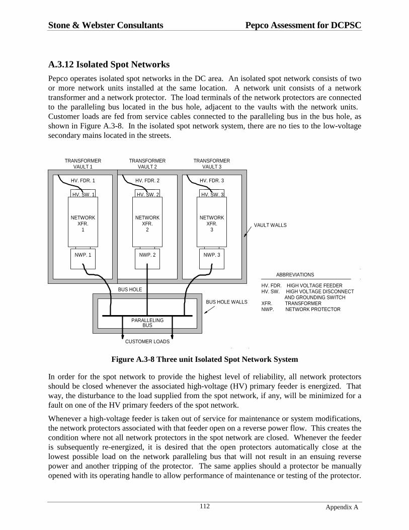
Stone & Webster Consultants Pepco Assessment for DCPSC
Appendix A112
A.3.12 Isolated Spot Networks
Pepco operates isolated spot networks in the DC area. An isolated spot network consists of twoor more network units installed at the same location. A network unit consists of a networktransformer and a network protector. The load terminals of the network protectors are connectedto the paralleling bus located in the bus hole, adjacent to the vaults with the network units. Customer loads are fed from service cables connected to the paralleling bus in the bus hole, asshown in Figure A.3-8. In the isolated spot network system, there are no ties to the low-voltagesecondary mains located in the streets.
DISK #3PSCDCNWK2.FCW
NWP. 1
NETWORKXFR.
1
HV. FDR. 1
TRANSFORMERVAULT 1
NWP. 2
NETWORKXFR.
2
HV. FDR. 2
TRANSFORMERVAULT 2
NWP. 3
NETWORKXFR.
3
HV. FDR. 3
TRANSFORMERVAULT 3
BUS HOLE
PARALLELINGBUS
CUSTOMER LOADS
VAULT WALLS
BUS HOLE WALLS
HV. FDR. HIGH VOLTAGE FEEDERHV. SW. HIGH VOLTAGE DISCONNECT AND GROUNDING SWITCHXFR. TRANSFORMERNWP. NETWORK PROTECTOR
ABBREVIATIONS
HV. SW. 1 HV. SW. 2 HV. SW. 3
Figure A.3-8 Three unit Isolated Spot Network System
In order for the spot network to provide the highest level of reliability, all network protectorsshould be closed whenever the associated high-voltage (HV) primary feeder is energized. Thatway, the disturbance to the load supplied from the spot network, if any, will be minimized for afault on one of the HV primary feeders of the spot network.
Whenever a high-voltage feeder is taken out of service for maintenance or system modifications,the network protectors associated with that feeder open on a reverse power flow. This creates thecondition where not all network protectors in the spot network are closed. Whenever the feederis subsequently re-energized, it is desired that the open protectors automatically close at thelowest possible load on the network paralleling bus that will not result in an ensuing reversepower and another tripping of the protector. The same applies should a protector be manuallyopened with its operating handle to allow performance of maintenance or testing of the protector.
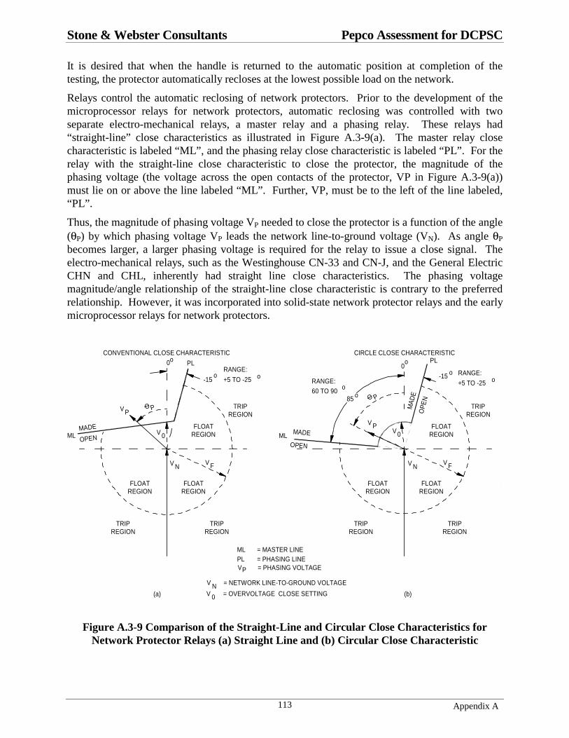
Stone & Webster Consultants Pepco Assessment for DCPSC
Appendix A113
It is desired that when the handle is returned to the automatic position at completion of thetesting, the protector automatically recloses at the lowest possible load on the network.
Relays control the automatic reclosing of network protectors. Prior to the development of themicroprocessor relays for network protectors, automatic reclosing was controlled with twoseparate electro-mechanical relays, a master relay and a phasing relay. These relays had“straight-line” close characteristics as illustrated in Figure A.3-9(a). The master relay closecharacteristic is labeled “ML”, and the phasing relay close characteristic is labeled “PL”. For therelay with the straight-line close characteristic to close the protector, the magnitude of thephasing voltage (the voltage across the open contacts of the protector, VP in Figure A.3-9(a))must lie on or above the line labeled “ML”. Further, VP, must be to the left of the line labeled,“PL”.
Thus, the magnitude of phasing voltage VP needed to close the protector is a function of the angle(θP) by which phasing voltage VP leads the network line-to-ground voltage (VN). As angle θP
becomes larger, a larger phasing voltage is required for the relay to issue a close signal. Theelectro-mechanical relays, such as the Westinghouse CN-33 and CN-J, and the General ElectricCHN and CHL, inherently had straight line close characteristics. The phasing voltagemagnitude/angle relationship of the straight-line close characteristic is contrary to the preferredrelationship. However, it was incorporated into solid-state network protector relays and the earlymicroprocessor relays for network protectors.
V N
V 0
0o
V P
V N
0o
V N = NETWORK LINE-TO-GROUND VOLTAGE
V 0
VP = PHASING VOLTAGE
(a) (b)
CONVENTIONAL CLOSE CHARACTERISTIC
-15o
MADE
OPEN
V P
CIRCLE CLOSE CHARACTERISTIC
= OVERVOLTAGE CLOSE SETTING
V 0
OPE
N
MA
DE
-15 RANGE:
+5 TO -25 o
RANGE:
+5 TO -25 o
ML
PLPL
ML
RANGE:60 TO 90 o
ML = MASTER LINEPL = PHASING LINE
o
85 o
FLOATREGION
FLOATREGION
FLOATREGION
TRIPREGION
TRIPREGION
TRIPREGION
FLOATREGION
FLOATREGION
TRIPREGION
TRIPREGION
FLOATREGION
TRIPREGION
MADE
OPEN
DCPSC05.FCW
V F V F
O P
O P
Figure A.3-9 Comparison of the Straight-Line and Circular Close Characteristics forNetwork Protector Relays (a) Straight Line and (b) Circular Close Characteristic

Stone & Webster Consultants Pepco Assessment for DCPSC
Appendix A114
With the most recent microprocessor relays for network protectors, the user can select the type ofclose characteristic that the relay will exhibit, either straight line or circular as in Figure A.3-9(a)and (b) respectively. With the circular close characteristic, the magnitude of the phasing voltageVP needed to make the close contacts and issue a close signal to the protector is independent ofthe phasing voltage angle, θP. Whenever VP equals the circle radius, V0 in Figure A.3-9(b), therelay issues a close signal. Practically, this means that the load on the spot network needed to geta protector to automatically close is independent of the load power factor angle. Furthermore, amore leading phasing voltage does not require a greater load on the network to cause automaticclosing of the protector, as is inherent with the straight-line close characteristics.
With the straight-line close characteristic, as the phasing voltage angle goes more leading, theensuing real power flow in the protector following closure is higher. Therefore, it is not logicalto require a higher phasing voltage magnitude at larger phasing voltage angles, as inherent withthe straight-line close characteristic.
With reference to Figure A.3-9(b), a relay with the circular close characteristic, having a radiusV0, also has blinders defining the extremities of the close characteristics.
The circular close characteristic is recommended for use in network protectors for isolated spotnetworks. This allows the protector to close at a lower load on the network, thereby helping tokeep all network protectors closed regardless of the load on the spot network. This in turnenhances the reliability of the network system.

Stone & Webster Consultants Pepco Assessment for DCPSC
Appendix A115
A.3.13 Technical Inaccuracies
The ABB study is very thorough in its evaluation of Pepco with regards to System Analysis,Engineering Design Practice, and Diagnostic and Condition Assessment. However, severaltechnical inaccuracies will be mentioned even though they do not alter the main findings of theABB study.
A.3.13.1 Cable Burn Thru Currents
The following is written in Section 4.8.2, subsection “Cable Burn-thru”. “It is stated in thissection that 3200 A (based on figure 4-15 on page 4-78 of the Standard Handbook for ElectricalEngineers, 13th ed.) is sufficient to burn clear a 250 kcmil copper cable, and therefore limitersneed only be applied if predicted fault currents are less than this value”.
Figure 4-15 on page 4-78 of the Standard Handbook for Electrical Engineers, gives the time toraise the temperature of copper conductors from 40 degrees C to 1083 degrees C when a currentis in the conductor for short times where radiation is neglected. In effect, the equation assumesthat all heat generated from the I2R losses in the conductor is stored in the conductor and raisesits temperature. These times are based on the equation developed by Onderdonk, equation 4-36in the handbook. This equation is given below.
234234
log33 10
2
++=
a
m
TT
tAI
(4-36)
In this equation, the terms are:
I = Conductor current in amperes rms
A = Conductor cross sectional area in circular mils
t = Time in seconds
Tm = Melting temperature of copper = 1083 degrees C
Ta = Ambient temperature of copper = 40 degrees C for the curves
Both the EEI Underground Systems Reference Book , 1957 edition, and the WestinghouseElectrical Transmission and Distribution Reference Book , 1950 edition, contain a table givingthe “minimum current in Amperes in each conductor on both sides of a solid fault on single-conductor cables to burn off the fault”. Neither of these references is clear in the basis for thenumbers in the table. Regardless, for the 250 kcmil copper cable, the current is given as 3200amperes, the same value cited in the ABB report and Pepco documents. The EEI publicationreferences the Westinghouse publication, and the Westinghouse publication indicates the tablesare based on tests reported in a 1931 paper, and unspecified calculations. The paper is titled,“Burn-Off Characteristics of AC Low-Voltage Network Cables”, by Sutherland and MacCorkle,AIEE Transactions, Vol. 50, No. 3, September 1931.
In summary, the curve in the Standard Handbook for Electrical Engineers gives the time to raisethe temperature of copper to the fusing temperature when a current is passing through theconductor. There is no heat generated by arcing or by I2R losses from contact resistance as whentwo bare conductors are touching one another. In contrast, the tests described in the AIEE paper

Stone & Webster Consultants Pepco Assessment for DCPSC
Appendix A116
resulted in tables giving the time to burn clear for faults initiated in accordance with the testconditions. Specifically, the AIEE paper states,
“Copper to copper faults, in single-conductor a-c low-voltage (120/208 volts) networkcables, made by the taping of the bared conductors overall and thereby obtaining a contactlength of approximately three inches between conductors will clear at the location of thefault within a period of the order of one minute (usually less) provided the followingminimum values of short-circuit current flowing into the fault are maintained during theshort circuit.”
There is no indication of the contact pressure between the two bare conductors when tapedtogether, but apparently it is such that when energized the losses in the contact resistance result inmelting and burning clear of the cables at the cited current level and higher.
The table in the original AIEE paper is reproduced below. Note that the 250 kcmil conductorsize is not included. It is believed that the value for the 250 kcmil cable was obtained by eitherinterpolation or calculation.
Constant Values of Short Circuit Current, AmpsConductor Size Per Conductor in Test Circuit Total
4/0 3000 6000350 kcmil 4000 8000500 kcmil 5000 10,000
A.3.13.2 Network Protector Relay Characteristics
Section 7.0 of the ABB Report discusses the settings used by Pepco for the network relays thatcontrol the automatic operation of its network protectors. On page 65, it is stated that, “If phaseshave been reversed across the network protector, the phasing relay will not allow it to close. Thisis an important safety feature of the network protector”.
Network protectors with the electro-mechanical relays typically have two separate relays, themaster relay and the phasing relay. The master relay is used to control both the automatictripping and automatic closing of the protector. The phasing relay is used only to control theautomatic reclosing of the protector. For a protector to automatically close, both the master relayclose contact and the phasing relay close contact must make. If phases are reversed, the masterrelay close contact will be open, but the phasing relay contact will be open or closed dependingon how the phases are reversed. Thus, if phases have been reversed across the network protector,it is the master relay that prevents the network protector from closing automatically.

Stone & Webster Consultants Pepco Assessment for DCPSC
Appendix A117
A.3.14 Review of Attachment #6
Attachment #6 of the ABB Report details the ampacity study performed by CTI Power Systemfor ABB T&D Company. The following are comments on the ampacity study.
• On the drawing for grid # 781390-381588, Case #2, the paper-insulated cable does not showa lead sheath. Paper Insulated Lead-Covered Cables (PILC) are standard on Pepco’s system.
Calculations with the heading 100a501f.txt:
• The page layout makes it very difficult to read and interpret the input data and the calculatedresults.
• The listing shows “No Shield Losses.” There will be sheath losses for the 13.8 kV single-conductor PILC cables listed.
• The load factor for the secondary 208 V cables is correctly listed as 50%.
• The load factor for the 13.8 kV primary cables is listed as 50%. Pepco’s design criterion is75%.
• In one of the tables, the sheath thickness for both the 208 V and the 13.8 kV cables is listedas 0.0001. No dimension is listed.
The factors listed above will have an effect on the ampacity rating of the cable circuits but it isnot possible to determine the effect without performing the calculations. Therefore, it isproposed that additional ampacity calculations be performed where the cables are correctlymodeled.

Stone & Webster Consultants Pepco Assessment for DCPSC
Appendix A118
Appendix A.4
REVIEWS OF
Georgetown Area Network System Evaluation
ABB Final Report May 21, 2001
And
4 kV System Load Flow and Reliability Analysis
Final Report March 9, 2001
Prepared by Stone & Webster Consultants
For the Public Service Commission of the District of Columbia
Submitted September 28, 2001
A.4.1 Purpose of This DocumentAt the request of the Public Service Commission of the District of Columbia, Stone & Websterreviewed the two documents “Potomac Electric Power Corporation Georgetown Area SystemEvaluation Washington DC” ABB Final Report dated May 21, 2001 which is bound with "Pepco4kV System Load Flow and Reliability Analysis" ABB Final Report dated March 9, 2001. Thisreview includes information obtained during a visit to ABB's offices in Raleigh, NC.
A.4.2 SummaryThe intention of Pepco's design criteria for its network systems is to be able to operate at systempeak without overloading secondary cables, even with one feeder out of service. From theresults of the ABB load flow analysis, the Georgetown East and North networks are not able tohandle peak load conditions without overloading some secondary cables, even with all primaryfeeders in service. During a single contingency many secondary cables are severely overloadedas well as some network transformers. This is the most significant result of the ABB analysis,because secondary cables have been implicated in a number of manhole events. Thisfinding also raises concerns about the performance of the remaining network systems in DC,which emphasizes the need to expedite the underground network modeling. Pepco hasreinforced secondary cables in Georgetown based on this analysis to improve reliability until theGeorgetown plan is implemented.
The 4 kV study analyzed performance of the Georgetown 4 kV system based on reliabilityindices and load flow analysis. Overall, the study found:
Stone & Webster Consultants Pepco Assessment for DCPSC
Appendix A119
• The reliability indices (SAIDI, SAIFI) of the 4 kV radial distribution system in Georgetownreflect substandard performance. The 5-year record of outage statistics indicatessignificantly higher failure rates than experienced in new underground systems.
• Overloaded 4 kV cables under peak system load conditions.
• A primary feeder with a voltage drop in excess of 4%.
The study supports Pepco’s decision to convert the 4 kV radial distribution system in theresidential area of Georgetown adjacent to the network system to a 13 kV loop system.
A.4.3 Purpose of the Network System EvaluationFrom the introduction to the ABB report (page 3):
"The objectives of the evaluation were to:
• Develop a computer model representative of the distribution system in theGeorgetown area, and perform a loading and contingency evaluation of that system.
• Use the results from the loading and contingency evaluation to identify criticalequipment and potential weak spots in the distribution system.
• Integrate the findings of this system analysis with conclusions of the conditionassessment performed earlier, as well as other PEPCo knowledge, to create short-termand long-term recommendations for the system in the Georgetown area.
The scope of the analysis was limited to the following:
• Modeling and analysis of all 13.8 kV feeders from Substation #12 supplying theGeorgetown area.
• Modeling and analysis of the Georgetown distributed low-voltage grid (120/208V)supplied from Substation #12.”
A.4.4 Summary of Results and Critique of the Network System EvaluationAs presented in the report, the work involved development of an analytical model of theGeorgetown network systems using ABB software, and simulation of a number of load flowcases to investigate cable loading under system normal and contingency conditions. ABB'swritten interpretation and discussion of the results is brief if viewed as a freestanding study withcarefully drawn conclusions. However, our interview of ABB consultants provided significantinsight to their methodology and interpretation of study results. ABB's investigation providedPepco with an analytical simulation of the Georgetown network system together with selectedcalculation results. Pepco has used the results to assess the condition of the Georgetown system.The value of the study lies in the calculation results themselves as graphically presented in thereport. Moreover, since Pepco worked closely with ABB in developing and calibrating themodels, Pepco gained knowledge of these analytical techniques that can be applied to themodeling of the other networks in DC.
Stone & Webster Consultants Pepco Assessment for DCPSC
Appendix A120
The analytical model was based on the highest system load level Pepco experienced prior to dateof the study. This occurred at midday on July 6, 1999. Measured values of primary feedercurrent for the four Georgetown networks were available for the peak hour. After developing theelectrical interconnection model and individual loads, the analytical model was scaled to makefeeder currents correspond to the measured loads. Within the scope of the study it does notappear that any extensive attempt was made to check the model against measured current in thesecondary conductors. In several ways the ABB study is a work-in-progress rather than afinished product. This is discussed further below.
It was not possible for Stone and Webster to analyze the detailed data that ABB used to developthe network system electrical connections. ABB appears to have applied well known proceduresfor digital computer load flow simulations, which have been performed by the industry for nearly40 years.
ABB presented their results in the form of drawings of the system configuration with cablesoperating within ratings shown in green and overloaded cables shown in red. Some significantobservations from the cases presented are:
• Figure 1, page 7 shows overloaded secondary cables under system normal peak loadconditions in the East Network. In other words, with all feeders in service some secondarycables are overloaded during system peak.
• Figure 5, page 11 shows overloaded secondary cables under system normal peak loadconditions in the North Network.
• Additional overloaded secondary cables in the East Network are also shown
with Feeder 15401 outage (Figure 8, page 15),
with Feeder 15402 outage (Figure 10, page 17),
with Feeder 15404 outage (Figure 14, page 21).
• Additional overloaded secondary cables in the North Network are also shown
with Feeder 14556 outage (Figure 41, page 48),
with Feeder 14559 outage (Figure 47, page 54).
• Figure 34, page 41, (and others) shows primary cable overloading in the West Network undersingle primary feeder outages.
The intention of Pepco’s design criteria for its network systems is to be able to operate at systempeak without overloading secondary cables, even with one feeder out of service. From theresults of the ABB load flow analysis, the Georgetown East and North networks are not able tohandle peak load conditions without overloading some secondary cables, even with all primaryfeeders in service. During a single contingency many secondary cables are severely overloadedas well as some network transformers. This is the most significant result of the ABB analysis,because secondary cables have been implicated in a number of manhole events. It alsoraises concerns about the performance of the remaining network systems in DC, whichemphasizes the need to expedite the underground network modeling
The accuracy of the ABB analysis might be argued based on several considerations. Forexample, the model was checked on overall total primary feeder loading for each network. A
Stone & Webster Consultants Pepco Assessment for DCPSC
Appendix A121
more accurate check would be to use the individual feeder currents at the time of the overall peakload. Secondary current distribution could be verified by clamp-on ammeter measurementstaken as part of the manhole inspections. Even considering the limitations on the accuracy of themodel, there is no reason to suspect the overall observation that secondary cables are overloadedin Georgetown with one primary feeder outage and likely under system normal peak loadconditions. Pepco has reinforced secondary cables in Georgetown based on this analysis toimprove reliability until the Georgetown plan is implemented.
It will be necessary for Pepco to develop an analytical model for the network system as it willappear after completion of the Georgetown plan to assist in specifying the size and number ofsecondary cables. Pepco has purchased the EasyPower load flow software, which has thecapability of performing the required analysis. Once the Georgetown plan has been completed,the analytical model should be calibrated by spot measurements of primary and secondary cablecurrents.
Identification of overloaded cables in the ABB report is an incentive for Pepco to proceed to theanalysis of the other secondary networks in their system to try and identify other areas ofoverloads that could develop into fault conditions.
The manhole inspection program provides measurements of secondary cable currents at the timeof that particular manhole inspection. While the use of these measurements is limited by normalload variation over time, availability of measured currents will be of benefit to engineersdeveloping analytical models of the remaining Pepco networks.
A.4.5 4 kV System Load Flow and Reliability AnalysisThe 4 kV study analyzed performance of the Georgetown 4 kV system based on reliabilityindices and load flow analysis. Overall, the study found:
• The reliability indices (SAIDI, SAIFI) of the 4 kV radial distribution system in Georgetownreflect substandard performance. The 5-year record of outage statistics indicatessignificantly higher failure rates than experienced in new underground systems.
• Overloaded 4 kV cables under peak system load conditions.
• A primary feeder with a voltage drop in excess of 4%.
Planned changes to the low voltage network system in Georgetown will impact the 4 kV radialdistribution system because the two systems overlap in many manholes. The Georgetown planwill move some residential load off of the low voltage network system. This load if added to the4 kV radial distribution system in Georgetown would only increase the stress on it. The resultsof this study support Pepco’s decision to convert the 4 kV radial distribution system in theresidential area of Georgetown adjacent to the network system to a 13 kV loop system.

Stone & Webster Consultants Pepco Assessment for DCPSC
122 Appendix A
Appendix A.5
A.5.1 Pepco’s Original Priority Definitions - Manhole Reliability Inspection
Priority I: Immediate corrective action required within 6 months
• Cable smoking (CS)• Joint smoking (JM)• Insulation damage (ID)• Overloading > 120% in summer• Overheating > 175º FAssess cable leak (CL), joint swelling (JS), burnout visible (BV) & joint leaking (JL) conditioninformation to determine Priority I or II; assess deformed joint (DJ) condition information todetermine Priority I, II or III
Priority II: Corrective action required within 12 months of inspection
• Braided cable (BC)• Overloading: 100 % > load > 120%• Overheating: 150º F > measured max. temp > 200º FAssess neutral corroded (NC), deformed joint (DJ) & upright support (US) condition informationto determine Priority II or III.
Priority III: Corrective action required within 18 months of inspection
• Deformed joint (DJ) condition not warranting priority I or II status• All remaining reportable cable or joint conditions• Overheating: 150º F > measured max. temp > 175º F
Reportable Condition Not Prioritized:
• Water• Debris• Asbestos• Minor-rereacking• Cables not tied.
D.C. Case No. 991S&W D.R. No. 3, Q.1
Response No. 1Attachment A

Stone & Webster Consultants Pepco Assessment for DCPSC
123 Appendix A
A.5.2 Pepco’s Revised Priority Definitions - Manhole Reliability InspectionRevision: 10-19-01
Priority 0 (Urgent): Corrective action required Immediately or within 5 days
Perform repairs immediately or within 5 days where the identified deficiencies have causedoutages, or present imminent risk of causing outages, or serious safety or environmental risk.
• Cable smoking (CS)• Joint smoking (JM)• Insulation damage (ID) – Bare Conductor• Burnout Visible• Loading greater than 140% of rating• Heating greater than 200º F• Elevated Gas Readings Reported to Gas Company
Priority 1: Corrective action required within 6 months of inspection
• Insulation damage (ID)• Loading between 120% and 140% of rating• Heating between 175º F and 200º F• Open Limiters
Assess cable leak (CL), joint swelling (JS), joint leaking (JL), deformed joint (DJ) & neutralcorroded (NC) condition information to determine Priority 1 or 2.
Priority 2: Corrective action required within 12 months of inspection
• Braided cable (BC)• Loading between 100 % and 120% of rating• Heating between 150º F and 175º F
Assess upright support (US) condition information to determine Priority 2 or 3.
Priority 3: Corrective action required within 18 months of inspection
• Re-Racking• Cables not secured• Structural Repairs• Retag Feeders and Buses• All remaining Reportable Non-electrical conditions
Non-Reportable Referrals:
• Water• Debris• Cracked Wall• Other
D.C. Case No. 991S&W D.R. No. 3, Q.1
Update to Response No. 1Attachment A

Stone & Webster Consultants Pepco Assessment for DCPSC
Appendix B124
APPENDIX B
ANALYSIS OF REPORTS & FILINGS PREPARED BY OTHERPARTIES
Contents
1. REVIEW OF Downes Associates Report Dated October 31, 2000
2. REVIEW OF Office of the Peoples Council’s Comments in Response to Order No. 12036

Stone & Webster Consultants Pepco Assessment for DCPSC
Appendix B125
Appendix B.1
REVIEW OF
Downes Associates Report
Dated October 31, 2000
Prepared by Stone & Webster Consultants
For the Public Service Commission of the District of Columbia
Submitted September 27, 2001
B.1.1 Purpose of This DocumentAt the request of the Public Service Commission of the District of Columbia, Stone & Websterreviewed the document "Report to the District of Columbia Public Service Commission FormalCase 991 in the Matter of the Investigation into Explosions Occurring in or Around theUnderground Distributions Systems of the Potomac Electric Power Company," submitted byDownes Associates, Inc. on behalf of the Office of the Peoples Council of the District ofColumbia.
B.1.2 SummaryThe Downes report contains several reasonably valid conclusions and recommendations. As thereport is about ten months old, it appears that Pepco has taken action on many of therecommendations made by Downes. However, we disagree with Downes’ assertion that age isthe primary causative factor and GIS the primary solution to failures of the underground system.
On pages 26 to 29, the section “Long-Term Solutions to Problems” relies heavily on the premisethat age is the primary factor in failures, and that a Geographic Information System (GIS) is thesolution. We do not support these assertions. Instead, we believe loading is the most significantfactor. Therefore, Pepco’s immediate need is an electrical analytical model of the undergrounddistribution system, especially the secondary networks, to determine loading patterns both withall circuits in service and during single contingencies. Such models would identify locations ofexcessive electrical loading and potential cable failures. GIS does not perform the analyticalelectrical system modeling and simulation that is crucial for predicting overloads and planningsystem improvements. In order to accomplish this, Pepco has acquired EasyPower, which is aload flow program.
Downes also criticizes Pepco's failure analysis. Pepco does not send a forensic investigator toevery failure event. Regarding failure analysis, Pepco issued the document “InvestigatingEquipment Failure” on January 24, 2001, marked “pending approval.” Completion andimplementation of the procedures contained in that document would meet the requirements ofthe Downes first recommendation.

Stone & Webster Consultants Pepco Assessment for DCPSC
Appendix B126
B.1.3 Comments on the Downes RecommendationsPepco has already addressed some of the recommendations in the Downes report dated October31, 2000. The comments below refer to the number of the Downes recommendations found onpages 31-33.
B.1.3.1 Downes Recommendat ion 1
This recommendation regards failure analysis. Pepco issued the document “InvestigatingEquipment Failure” on January 24, 2001, marked “pending approval.” Completion andimplementation of the procedures in this document would satisfy the intent of thisrecommendation.
B.1.3.2 Downes Recommendat ion 2 and 3
Pepco is continuing its reliability inspection reporting and its manhole inspection program,similar to these recommendations by Downes.
B.1.3.3 Downes Recommendat ion 4
Some of the “data gaps” referenced in this recommendation will be filled by the manholeinspection program, such as determining operating temperatures of cables. However, otherinformation such as cable and splice age is difficult to obtain. . We believe the most importantgap in data relating to Pepco’s underground distribution system is knowledge of electricalloadings, which can only be determined by load flow studies under system normal andcontingency conditions supported by field measurements. Focusing and expediting effort onanalyzing cable loads would be far more valuable than trying to assess age.
B.1.3.4 Downes Recommendat ion 5
This is part of the continuing assertion in the Downes report that age is the major issue. Wemaintain that loading is the major issue, not age alone. Age can be a primary factor for specificequipment such as braided cable, but it must be ascertained on a case-by-case basis. Forexample, Pepco automatically replaces braided secondary cable when found. The braidedsecondary cable has deteriorated over time and is considered as old equipment. PILC, on theother hand, is a hermetically sealed system that takes indeterminate decades to deteriorate undernormal operating conditions. Therefore, even if a braided cable and a PILC cable are the sameage, only the braided cable will be considered as old. The Georgetown Project will replace theterra cotta (clay pottery) duct banks because many of them are now damaged. Although terracotta does not deteriorate over time, the brittle nature of this material often results in breakageunder mechanical forces. Thus, terra cotta duct has been declared obsolete because othermaterials (e.g., fiberglass, PVC, PE, etc.) are stronger.
B.1.3.5 Downes Recommendat ion 6
This overstates the advantages of GIS. On page 32, “Finally, circuit loading data from….couldthen be correlated to network loading and age of equipment.” Loading on the secondary cable

Stone & Webster Consultants Pepco Assessment for DCPSC
Appendix B127
circuits (mains) of the low-voltage network is not available through SCADA data, contrary towhat is stated on page 32. There is no instrumentation measuring loads on the secondary cablecircuits (mains), and installation of such instrumentation would be prohibitively expensive.Low-voltage cable loads are presently being measured by use of clamp-on ammeters duringmanhole inspections, and are only valid for the conditions specific to the moment themeasurement is taken. Pepco is presently evaluating the use of microprocessor relays fornetwork protectors. These relays perform the normal control functions, and in conjunction witha communications system, have the capability to detect overloads on network transformers andsound an alarm at a field office. However, this system does not monitor the loads in secondarycables. This is why Stone and Webster is recommending that first priority be given to analyticalload flow modeling of the secondary networks.
B.1.4 Geographical Information System and Load Modeling
B.1.4.1 Page 28
Downes states: “With the development during the last few years of powerful analytical softwareprograms for the utility industry, utility computer systems can now be employed to develop justsuch preemptive planning thus affording the utilities mitigation options previously unattainable.”“Such software solutions are referred to as Geographical Information Systems (“GIS”).” Onpage 29 Downes states: “Yet, the power of GIS system properly populated by comprehensivedata bases would probably be the single most valuable tool Pepco could employ to understandthe pattern of system failures and to develop effective mitigation and remediation strategies.”These statements may indicate confusion regarding what GIS can and cannot do. Note that aGIS is primarily a means for tracking physical equipment installed on the system.
Stone & Webster believes the number one priority should be to develop the electrical load flowmodels from which the loads on the distribution system components can be determined with allcircuits in service and during single contingencies. Such models would identify locations ofexcessive electrical loading and potential cable failures. GIS is not the analytical tool required toperform the electrical studies needed to detect system overloads.
B.1.4.2 Page 26
Downes says that an accurate electrical system model using a load flow computer programshould enable Pepco to identify components that will be overloaded. GIS does not handle theanalytical electrical system models that are crucial for predicting overloads and planning systemimprovements. Electrical models for performing electrical analyses of the loads on circuits aresimulated by load flow programs. Pepco plans to use EasyPower, which is a load flow program.
System modeling is briefly discussed on page 26, but misses the point of how crucial analyticalelectrical models are to assessing the loading of individual cables, especially the secondarynetworks. Development of an analytical model of a secondary network includes careful analysisof amount and geographical location of load so the load can be applied at the proper electricallocation within the network. Even knowing the location of loads, a computer evaluation isnecessary to determine the loading on individual cables because it is not possible to predict byinspection how the load divides among the individual cables.

Stone & Webster Consultants Pepco Assessment for DCPSC
Appendix B128
From the physical equipment location standpoint (GIS’s purpose), Pepco’s distribution systemshave been evolving over the last 100 years, so one should not be very critical for Pepco nothaving its system recorded with GIS which only became available in the last few years. Atremendous amount of time and resources are required to input the data of a large system into aGIS database. Any system that will electronically link energy databases, GIS databases, CADdatabases, with the load flow program will help in reducing costs and eliminating errors.However, creating these databases and linking them to the load flow program, EasyPower, willrequire a significant investment. It appears that Pepco has programs in place that will ultimatelyprovide for this. However, it will take ongoing efforts and resources to keep it up-to-date.
B.1.4.3 Page 2
Downes states: “Pepco’s implementation of an advanced geographical information systemshould be accelerated so that it can be used to track, predict, and prevent future manholefailures.” We don’t think there is anything that can be done that will prevent all failures inmanholes in the future. Perhaps the data available from such systems will help in reducing thenumber of failures, but certainly will not prevent all such failures.
B.1.5 Failure Analysis
B.1.5.1 Page 12
Downes states: “Secondary cable faults apparently resulted from cable connector failures, splicefailures, and basic cable insulation breakdowns.” On pages 15 and 16 Downes criticized Pepcofor not preserving failed equipment and performing failure analysis.
Had Pepco conducted more failure analyses, more insight into common failure causes may havebeen gained, particularly in PILC primary cable splices where many failures occurred. Indeed,Pepco does not send a forensic investigator to every failure event, which may occur in the middleof the night. The failures of August 8 and 9, 2001 occurred at 10:20 PM and 3:19 AM,respectively. Pepco has said that each manhole event is examined to determine what happened,but most often they don’t conduct a formal investigation into the root cause of the failure.
A forensic investigator gathers data for the failure investigation, takes measurements, documentsthe site, and carefully removes the failed components. Such activities can delay restoration ofservice, particularly in the radial systems. The need to restore service to customers as quickly aspossible places a practical limit on the amount of post-mortem analysis possible. When a circuitfails, the repair crew is pressed to find the failure, repair it, and return the feeder to service in asshort a time as possible. Repair crews may inadvertently destroy evidence in the process ofremoving, repairing and replacing failed equipment to restore service in the least possible time.Moreover, the point of failure may be destroyed by the event itself.
B.1.5.2 Page 19
Downes states, “Based on the data provided, it is the opinion of Downes Associates that aspecified and related common cause (or causes) of the recent failures experienced by Pepco willbe difficult to discover without better organized data and more advanced tools for analyzing such

Stone & Webster Consultants Pepco Assessment for DCPSC
Appendix B129
data.” Stone & Webster agrees with this and that Pepco should enhance their failure analysis, inparticular for primary splices and low-voltage cable failures.
Regarding failure analysis, Pepco issued the document “Investigating Equipment Failure” onJanuary 24, 2001, marked “pending approval.” Completion and implementation of theprocedures contained in this document would meet the intent of the first Downesrecommendation.
B.1.6 Equipment AgeThere seems to be a premise in the Downes report that equipment age is the major factorinvolved in equipment failures.
B.1.6.1 Page 2 - Recommenda tion 5
Downes alleges that a significant cause of the failures in cables and splices is due to the age ofthe equipment.
We don’t argue the validity of the typical bathtub failure curve (shown below) that might applyto cables, transformers, and perhaps splices. However, we question the significance of agesolely on failure rates for cables, splices, and transformers, and at what point in time the curvesstart to turn up steeply. A more important measure of when to change out a cable, transformer,or a piece of equipment is the failure rate or performance. Figure B.1-1 illustrates how loadingmight affect the life of an underground distribution system.
TIME IN SERVICE
FAIL
UR
E R
ATE
PE
R U
NIT
LOADLEVEL 3
LOADLEVEL 2
LOADLEVEL 1
LOAD LEVEL 3 > LOAD LEVEL 2 > LOAD LEVEL 1
PSCDC DISK # 2BATHTUB1.FCW
Figure B.1-1 Bathtub Failure Curves for System Components
In Figure B.1-1, the point at which the failure rate increases rapidly is not known, but in PILCcables and transformers, and perhaps in splices, the turn-up will occur earlier as the loadinglevels are raised. Other factors, such as submersion in water and chemicals, may affect the pointwhere the turn up occurs. Transformer standards, as well as AEIC standards for paper cables

Stone & Webster Consultants Pepco Assessment for DCPSC
Appendix B130
show that there is a loss of normal life expectancy when the operating temperatures exceed acertain value. In transformers, as the cellulose paper degrades from high temperatures, electricaland mechanical strength is lost. Perhaps they can withstand the stresses of normal currents andvoltages, but faults or transient overvoltages are more likely to initiate a breakdown.
B.1.6.2 Page 10
Downes quotes from Pepco’s 1997 plan for “L” Street Substation No. 21:“L Street Sub 21 is theoldest 13.8 kV substation on the Pepco system. Two of the four 34.5 /13.8 kV 20 MVAtransformers were installed in 1940 and the other two in 1941 and 1942. Past Studies by Civiland Substation Engineering indicated that no spare 20 MVA transformers are available. Also,switchgear is beyond its expected life and no replacement parts are available.” We interpret thisto mean that the concern with the transformers is the lack of a spare unit should one of the 20MVA units fail, not the transformer's age. However, Pepco’s standard transformer size is 50MVA and they probably have a spare 50 MVA unit or mobile unit. In any case, transformerfailures have not been a significant cause of manhole events in DC, which renders this discussionof transformers somewhat irrelevant to the manhole event issue.
Similarly, the main concern with the old switchgear is the lack of spare parts available forrepairs. Some utilities operating 60-plus-year-old network protectors are concerned not so muchwith the age, but whether they can purchase spare parts when required (motors, arcing contacts,shunt trip, etc.). A common practice in the industry (and military) is to salvage spare parts fromunits retired at other locations. On page 11 Downes states: “Assuming that records are complete,one could use the maintenance record of each individual transformer to determine the age offacilities which serve areas that have been subjected to manhole incidents in the past fewmonths.” A transformer's age does not accurately indicate the age of the cables in the area. Thetransformers at opposite ends of secondary mains are often installed years apart. Transformersare sometimes replaced by a larger size. Also, the secondary mains between two transformersmay consist of multiple sets of cables installed years apart. Since about 1993, Pepco replaces anetwork transformer by using an elbow connector on a short length of solid dielectric cablespliced to the existing PILC cable. The transformer's age does not indicate of the age of thePILC cable.
B.1.6.3 Page 7
Downes states while discussing Pepco plat plan drawings: “to determine if the necessaryinformation was readily available for determining either a cause of the recent cable and splicefailures or a pattern to the failures. Of particular interest was any information on the plats anddrawings that would indicate the age….” There may indeed be common mode problems withcertain types of equipment of certain ages, but other factors beside age may be more important inan underground electric distribution system. New cables may be overloaded and fail. Newsecondary cables could be installed and quickly become overloaded if the load growth in thelocal area is significantly greater than the planners anticipated. On the other hand, old PILCcable that has not been overloaded or externally damaged may continue to have satisfactoryreliability for indeterminate years.
Installed equipment drawings by their very nature do not contain loading information crucial tothe design of the system or for diagnosing failures. They also do not include the record of
Stone & Webster Consultants Pepco Assessment for DCPSC
Appendix B131
operating conditions that have to be reviewed in a failure investigation. While age is aconsideration, we believe the primary factor is system loading related to the rated capability ofinstalled equipment.
B.1.6.4 Page 18
Downes states: “OPC requested information concerning Pepco’s records regarding the age ofprimary and secondary underground cable circuits in the Company’s distribution system. In itsresponse dated May 21, 2000, Pepco responded that records designating age for circuits were notavailable.” Also on page 32 Downes states in part: “an excellent correlation exists to link theinstalled age of most of Pepco’s cable system to the age of the transformers in the variousnetworks.” Since a network primary feeder consists of many segments of cable betweenmanholes, all of the segments may not have been installed at the same time. Further, thedistribution system is very dynamic, i.e., certain cable segments may have been associated withdifferent circuits over time. Moreover, certain segments may have been fed from differentsubstations as load was transferred over time. Given such circumstances, how would onecalculate the age of a network primary feeder circuit? Is it the age of the oldest cable segment?Is it the age of the newest cable segment? Is it the average age of the cable segments? Is it thelength-weighted age of all cable segments? We seriously doubt if there is any utility that couldgive an accurate figure for the age of a primary feeder circuit, if for no other reason than there isconsiderable ambiguity in the meaning of circuit age. We also doubt that many maintain adatabase indicating the age of cable segments between manholes.
Stone & Webster agrees with Pepco’s approach: “Plans for replacement or enhancement ofequipment are developed based on the expected loading and the historical reliability performanceof the particular equipment.”
B.1.6.5 Page 20
Downes states: “ The remaining common attribute of the failures that may link them as to causeis that they have all occurred on a system which, on the whole, is aging, with specific materialsand equipment which may have already exceeded their expected useful life span.” Downescannot logically reach this conclusion because the age of the failed equipment is not known inmany cases. In the first paragraph, Downes basis for its conclusion is essentially: "Since Pepcohas not pinpointed the causes to anything else, the only thing left is age."
The discussion about old substation transformers and circuit breakers is like saying you have oldapples, therefore your oranges must be old too. Old age is a relative term. Age in and of itselfdoes not matter; but strength does. You can only conclude that old is weak if strength can beshown to be a function of age. An analogy from a more common form of material may help toillustrate the point. Is a new 2x4 pine stud stronger than a 50-year-old oak stud?
B.1.6.6 Page 20 (Continued)
Downes quotes an EPRI report: “Manholes, vaults, and service boxes are occasionally subject tosmokers, fires, and explosions. As the infrastructure of an underground distribution system ages,the number of these events will likely increase.” We suspect that the above statement made in
Stone & Webster Consultants Pepco Assessment for DCPSC
Appendix B132
the EPRI report is the opinion of the report’s author, but that the author has no data to supportthis opinion.
B.1.6.7 Page 21
Downes states: "all manmade materials will undergo molecular and composite degradation overtime. This is a basic law of thermodynamics." We disagree since thermodynamics as a sciencetreats the direction of processes, but says nothing about the rates at which the processes takeplace. Glass is a manmade material that lasts centuries or millennia. The fact that materialsdegrade is not by itself an indication of the time frame to failure. Degradation rates are afunction of more variables than time alone. Temperature is a significant factor in aging,especially with cellulose based materials.
B.1.6.8 Page 23
Downes states: “A normal practice throughout the utility industry is to increase the scrutinygiven to operating systems when they reach 20 to 25 years of age.” We do not think that is acorrect statement. A distribution transformer on a pole that was installed in 1950 receives nomore scrutiny than one installed in 1995. Only if it fails and blows a fuse does it get morescrutiny. The same applies in the distribution system to primary and secondary cables.
B.1.6.9 Page 23 (Continued)
Accounting practices for property depreciation are not a metric for insulation degradation. Lifefor accounting purposes is not based on actual anticipated physical life of the equipment inquestion.
B.1.7 Other Comments
B.1.7.1 Page 3
Downes states: “Although Pepco may characterize the violent explosions in electricaldistribution manholes as “relatively rare”, they are nevertheless too frequent when viewed inlight of system reliability and public safety concerns.” The Pepco system is designed to maintainservice on a network system with one feeder out of service. In most cases, faults on feeders tothe low-voltage secondary networks may displace a cover and make some smoke, but the impacton reliability is minimal. For example, the reports for August 8 and 9, 2001, which involvedfaults on primary feeders to the LV networks, resulted in no customer outages.
B.1.7.2 Page 3 (Item # 2)
Downes states: “Have weaknesses in Pepco’s business practices, such as internal record keepingor engineering standards contributed to the recent failures, or could improvements in thosesystems help to minimize the failures.” We are of the opinion that the engineering standardsused by Pepco are sound and are not the cause of the failures.

Stone & Webster Consultants Pepco Assessment for DCPSC
Appendix B133
Appendix B.2
REVIEW OF
Office of the Peoples Council’s
Comments in Response to Order No. 12036
Prepared by Stone & Webster Consultants
For the Public Service Commission of the District of Columbia
Submitted September 27, 2001
B.2.1 Purpose of This DocumentAt the request of the Public Service Commission of the District of Columbia, Stone & Websterreviewed the document "Office of the Peoples Council’s Comments in Response to Order No.12036." Our comments are directed to Attachment A, which is a report prepared by DownesAssociates, Inc. dated May 16, 2001, Engineering review of the "Final Report on Manhole EventTests for Pepco at Lenox."
B.2.2 SummaryDownes Associates discredits the EPRI work wherever possible. Five of their observations arediscussed below.
B.2.3 Downes Observation 1:Downes claims that the ability of slotted covers to vent combustible gases is intuitively plausible,but has not been demonstrated by EPRI’s tests.
Pepco has installed thousands of slotted manhole covers since release of the EPRI report. Thelist of manhole incidents, January 2001 to date, has several cases of solid covers displacement,with just one instance of a slotted cover displacement. The slotted cover displacement occurredduring restoration, not from the initial fault. This limited history supports the premise that use ofslotted covers will reduce the number of manhole cover displacements.
Slotted covers may prevent the build-up of gas and resultant explosion. Regarding dispersal ofcombustible gases: smoke has been observed rising from slotted covers during manhole eventsthat did not result in an explosion. Fire fighters know that a build-up of smoke is a potentiallyexplosive condition and respond by ventilating a fire scene. Dispersal of smoke with slotted

Stone & Webster Consultants Pepco Assessment for DCPSC
Appendix B134
covers is indicative that combustible material is being vented. The concept that slotted covershelp to remove combustible gases is reasonable, and nothing in the EPRI tests contradicts thatimpression.
It appears that EPRI did not attempt a quantitative analysis of gases in the manhole before eachtest. Verbal indications in discussion indicate they had difficulty obtaining ignition, whichwould support the premise that gases were being dispersed. It is hard to separate from the testresults whether observed differences in movement between manhole cover types were related togas dispersal or pressure relief.
B.2.4 Downes Observation 2:Downes claims “The test results indicate that vented covers, especially slotted covers, areineffective in substantially reducing the movement of manhole covers during an explosion.”
The comparison of cases in Tables 7-2 and 7-3 indicate one comparison (4% gas UL mixture)where the slotted cover rose 6 to 8 inches and the solid cover rose 4 inches. The solid cover casehas a footnote “The cover came up, released pressure, went down into the frame and then rockedreleasing pressure again.” It would be reasonable to deduce from this case that the two coversmoved about the same. All the other comparisons showed less movement for the slotted coverthan for the solid cover. The worst case (6% gas UL mixture which the report authorsconsidered to represent the worst possible case) had the slotted cover rising 9½ feet and the solidcover rising 10½ feet, not a large difference.
These cases in general show that slotted covers rise less than solid covers, and could providesome benefit in all but the worst cases.
B.2.5 Downes Observation 3:Downes claims: “In all tests when tethers were used, manhole covers were restrained. Nomeasurements were made of the possible damage caused by tethered covers.”
Compare tests 2-6 and 2-7 for slotted covers without and with tethers and 5% UL gas mixture.Without a tether the cover rose 1 foot 6.5 inches. With a tether the cover lifted 4 feet 2.5 inchesto the top edge. What this means is without a tether the lid rose flat and came back down again.With the tether the lid flipped over, with the top rising over 4 feet. The situation with the tetheris potentially more dangerous than without the tether because without the tether the effect of themovement is directly over the cover, but with the tether the cover can move into space adjacentto the hole.
On page 9 Downes claims “The only way to achieve this result (given the maximum explosivepower assumed in the EPRI tests) is to use a vented cover and bolt it to the manhole frame.”(Emphasis Downes’s) Bolting the cover to the manhole is not at all acceptable, because severaltests at Lenox resulted in movement of the roof slab and/or damage to the vault. An explosionsufficiently serious to raise a slotted cover could do additional damage if the cover were not freeto lift and relieve the pressure. Movement of a section of sidewalk or street beyond the coveritself is unacceptable.

Stone & Webster Consultants Pepco Assessment for DCPSC
Appendix B135
B.2.6 Downes Observation 4:Downes claims: “The effect of street debris is not adequately addressed in either report.”
Debris entering the manhole is an important consideration, and one that led to Pepco installingslotted covers in sidewalks and crosswalks but not in streets. We observed a slotted manholecover in a sidewalk under a tree where a number of leaves have already entered the manhole.This is an area that will have to be monitored by Pepco.
Downes says the grated manhole covers were rejected because they were more likely to clogwith debris than the slotted covers. Page 8-1 of the EPRI report states “During the tests thelinemen noted that it is difficult to remove the galvanized steel cover from the frame because ofits depth and the sharp edges.” The grated covers have other disadvantages besides debris, andso were not selected for installation.
B.2.7 Downes Observation 5:Downes claims: “There are a number of details in the report that are unclear.”
The section on a “baffle” raises an interesting question, but not one that would changeinterpretation of the report.
The discussion of discharged hot gases refers to measurements that do not appear to have beenpart of the test protocol, but in retrospect would have been useful data. Perhaps the videotape ofthe tests would shed some light and help answer the concern expressed by Downes (p12) aboutthe comparison of hot gases for the different types of covers.
Granted, the EPRI report could have been more thorough, especially in discussion ofobservations and conclusions. The report led Pepco to try installation of slotted covers, and isnow accumulating experience that alone will determine their effectiveness.

Stone & Webster Consultants Pepco Assessment for DCPSC
Appendix C136
APPENDIX C
STONE & WEBSTER’S DATA REQUESTS TO PEPCO

Stone & Webster Consultants Pepco Assessment for DCPSC
Appendix C137
C.1 Stone & Webster Data Request No. 1
Date: May 24 , 2001
1. Organization charts and discussion of the distribution, transmission, engineering, planning,construction, and/or any other functional areas relevant to our assessment
2. A description of the Pepco electrical system
3. A copy of all ABB, EPRI, other consultants, and Pepco reports relevant to our assessmentand to Pepco’s proposed modernization plans and projects for the Georgetown area
4. A copy of the proposed modernization plan
5. The names, titles, and phone numbers of all ABB, EPRI, and other consultants to Pepco whohave studied, analyzed, and/or prepared reports relevant to our assessment
6. A copy of Pepco’s maintenance, testing, and inspection policies, practices, and schedules forthe subject manhole facilities
7. A copy of Pepco’s engineering design and construction standards and materials for thesubject manhole facilities

Stone & Webster Consultants Pepco Assessment for DCPSC
Appendix C138
C.2 Stone & Webster Data Request No. 2
Date: June 1, 2001
1. Five (5) street maps of the Georgetown area showing the locations of manhole incidents foreach of the years 1997, 1998, 1999, 2000, 2001 to date
2. Five (5) street maps of DC showing the locations of manhole incidents for each of the years1997, 1998, 1999, 2000, 2001 to date
3. Five (5) street maps of the Georgetown area showing the locations of primary faults on theunderground system for each of the years 1997, 1998, 1999, 2000, 2001 to date
4. Five (5) street maps of DC showing the locations of primary faults on the undergroundsystem for each of the years 1997, 1998, 1999, 2000, 2001 to date
5. Street map showing the areas of DC served by Pepco’s underground distribution system
6. The manhole inspection sheet that lists what is actually being looked at during each manholeinspection
7. From the recent PHB Hagler Bailly Benchmark Survey T&D: results including reliabilityindices, O&M cost comparisons, operational comparisons, etc.
8. EPRI TR-106394, "Evaluation of Gases Generated by Heating and Burning of Cables" April1996 [Ref. 1 to EPRI WO-049296 Final report]
9. EPRI TR-109741, "Manhole and Service Box explosion Suppression and Mitigation"January 1998 [Ref. 2 to EPRI WO-049296 Final report]
Stone & Webster Consultants Pepco Assessment for DCPSC
Appendix C139
C.3 Stone & Webster Data Request No. 3
Date: July 6, 2001
1. The manhole projects prioritization scheme.
2. The current backlog of manhole projects by priority.
3. Underground line, maintenance, and conduit staffing levels located in DC, by classificationfor years-end 1990, 1995, 2000, and current.
4. Power Point or other presentations given to Productivity Improvement Working Groupregarding power delivery staffing, and system reliability.
5. Description of the four alternative plans considered for the Georgetown modernization andthe decision process and factors leading to the adopted plan.
6. Plans and timetables for implementation of GIS, OMS, mobile unit dispatch, and MAXIMO.Include current status and expected benefits of each (e.g., response time, reliability, costsavings, etc.)
7. Written description of the manhole inspection, data collection and recording processesincluding quality control of data input, random manhole reinspections, pick lists, and plansfor the MicroTrax project.
8. Training courses given to UG personnel in years 2000 and 2001. Include course titles,length, number of attendees, etc.
9. Composition, charter, and results of joint management/bargaining unit committee for trainingof UG line personnel.
10. Provide the training plan for the 33 new hires into the UG department.
11. Copy of the Power Distribution Group - Performance Measures 2001, dated 5/8/01.
12. Copy of the Power Distribution Group - Four Year Budget Analysis (1998-2001).
13. Copy of Customer Care - Historical Annual Distribution System Construction Spending(1995-Budget 2001).
14. Copy of the DC UG maintenance budget versus actual expenditures for the years 1995 todate.
15. Copy of the 2001 Customer Service and Power Distribution Construction Budget includingproject detail information sheets.
16. All internal reports on manhole incidents for the years 2000 and 2001 to date, both withinand outside Georgetown.
17. Plats of all manholes examined during the manhole inspection tour of June 19 and 20. Pleasesubmit in electric format readable by Word or 8.5" x 11’paper format (similar to what isprovided to the crews).
18. Procedure "for collection of data and materials for selected equipment failures" referenced inComments to Recommendation No. 1 in Pepco’s appendix "Supplemental Report to

Stone & Webster Consultants Pepco Assessment for DCPSC
Appendix C140
Comments Filed on May 15, 2000, Evaluating Pepco’s Reports About the Cause or Causes ofthe Manhole Explosions and in Response to the June 8, 2000, Staff Report".
19. Provide the SAIDI, SAIFI, and CAIDI indices for the DC service territory for the five years1996 - 2000 and 2001 to date.

Stone & Webster Consultants Pepco Assessment for DCPSC
Appendix C141
C.4 Stone & Webster Data Request No.4
Date: July 9 , 2001
Basis for Request:
Many of the type “E” events in year 2000 were “Cable Joint” or “Branch Joint” failures.Devices are available which can limit the magnitude as well as the duration of the fault currentflow from the substation to faults on network primary feeders. Whether the devices will beeffective in reducing or preventing “E” type failures can not be stated at this time. However,knowledge of the available fault currents and clearing times for faults on the substation bus andnetwork feeders will yield insight into whether the devices may be effective.
For each substation supplying 13 kV network feeders, provide the following information:
1. The current available for the three-phase fault on the bus to which the network primaryfeeders are connected. Provide the rms value of the symmetrical component, and theapproximate X to R ratio of the positive-sequence impedance.
2. The current available for the single line-to-ground fault on the bus to which the networkprimary feeders are connected. Provide the rms value of the symmetrical component of thesingle line-to-ground fault current, as well as the X to R ratio ( (2*X1 + X0)/ (2*R1 + R0)).
3. For a three-phase fault on the feeder side of breakers in the substation supplying the networkfeeders, the total time in cycles for the feeder breaker to interrupt the fault current from thesubstation end (relay time and breaker interrupting time).
4. For a single line-to-ground fault on the feeder side of the breakers in the substation supplyingthe network feeders, the total time in cycles for the feeder breaker to interrupt the faultcurrent from the substation end (relay time and breaker interrupting time).
Note: This request assumes that the substation supplying the network primary feeders has a busarrangement where the available fault current is the same on the feeder side of each feederbreaker.

Stone & Webster Consultants Pepco Assessment for DCPSC
Appendix C142
C.5 Stone & Webster Data Request No. 5
Date: July 13 , 2001
1. Provide the range in primary amperes for the pickup settings of the phase instantaneouscurrent relays used on dedicated network feeders supplied from 13 kV stations in the Pepcosystems in the DC area.
2. Provide the range in primary amperes for the settings of the ground instantaneous currentrelays used on dedicated network feeders supplied from 13 kV stations in the Pepco systemsin the DC area.
Note: Dedicated network feeders are those primary cable circuits supplying just Pepconetwork transformers with delta connected primary windings.
3. For government 13 kV primary feeders, are phase instantaneous current relays applied at thestation? If yes, provide the range in primary amperes for the pickup settings of the phaseinstantaneous current relays.
4. For distribution 13 kV primary feeders, are phase instantaneous current relays applied at thestation? If yes, provide the range in primary amperes for the pickup settings of the phaseinstantaneous current relays.
5. Provide a narative or a description of the procedures, methodologies, or calculations that arepresently employed by Pepco when designing a secondary network system, and whenevaluating the performance of an existing secondary network system, to determine if thecomponents of the system will be loaded above their rating under both normal conditions andsingle contingency conditions. For request 5:
a) Normal conditions are when all primary feeders of the network are in service and allnetwork transformers on each feeder are connected to the low-voltage network withtheir associated network protector, excluding the situation where a protector may beout of service for maintenance, or open due to light loading.
b) A single-contingency condition is when any one primary feeder of a given network isout of service such that all network transformers on the feeder can not supply powerto the secondary network. With one primary feeder out of service, the remainingprimary feeders and the associated network transformers and protectors must supplythe peak load of the network.
c) The components of interest are the primary feeder cables, the network transformers,and the street mains (sometimes called secondary mains or bus tie circuits).
6. Provide a copy of any standards or design guides describing the methodology for selectingthe size of the street mains (number of sets of cable and the size of the cable) in the low-voltage network systems.
7. Provide a copy of any standards or guides defining the frequency at which the loading of thecomponents in an existing secondary network system are determined to ascertain the systemperformance under both normal and contingency conditions.
Stone & Webster Consultants Pepco Assessment for DCPSC
Appendix C143
C.6 Stone & Webster Data Request No. 6
Date: July 26, 2001
1. A DC map where the manholes visited by Stone & Webster is plotted. Please use differentnomenclature for manholes and transformer vaults.
2. List of all of the network systems within DC - mark on DC map if possible.
3. Please provide the detailed series and time schedule of job experience training, jobprogression, testing, skills acquisition and demonstration, and certification process requiredto become a journeyman splicer. After attainment, what continuous education, refreshertraining, skills demonstration, or recertification requirements exist?
4. On an annual basis, please estimate the range (i.e., minimum to maximum) and averagenumber of splices made by a certified splicer.

Stone & Webster Consultants Pepco Assessment for DCPSC
Appendix C144
C.7 Stone & Webster Data Request No. 7
Date: August 15, 2001
From August 7 through 14, Pepco’s underground distribution system in DC experienced anumber of equipment failures, including a number of manhole events. Please respond to thefollowing set of question with two lists:
List A - Manhole events
List B - Equipment failures without manhole events
1. Where did it occur (manhole by grid number and street location, and sidewalk vs streetlocation, and substation/feeder, failure date & time)?
2. What is the approximate physical dimension of the vault?
3. What type of manhole covers, solid or slotted?
4. What was the manhole cover event type (List A)?
5. What type of equipment was in the vault, (cable type, voltage, radial/network, transformers,etc.)?
6. What type of equipment failed?
7. What was the reason(s) for the failures?
8. When had the manhole last been inspected?
9. What were the findings during inspection?
10. Had repairs been made, or scheduled but not repaired?
11. Has the peak load on the subject equipment been determined through calculation,measurement or both?
12. What were the findings with regard to peak loads on the subject equipment?
13. Was the equipment operating under a contingency (another circuit out)?
14. Submit any failure investigating reports prepared on the events.

Stone & Webster Consultants Pepco Assessment for DCPSC
Appendix C145
C.8 Stone & Webster Data Request No. 8
Date: September 7, 2001
Of 56 manhole events in Washington, DC, 15 occurred in manholes that had been inspected.
1. The manhole inspection sheets of the 15 inspected manholes where events occurred.
2. The event reports from the 15 manholes.
3. The failure investigation reports for the 15 events.

Stone & Webster Consultants Pepco Assessment for DCPSC
Appendix D146
APPENDIX D
STONE & WEBSTER’S MONTHLY REPORTS TO THE DCPSC

Stone & Webster Consultants Pepco Assessment for DCPSC
Appendix D147
D.1 Pepco Assessment Monthly Report - May and June 2001Stone & Webster initiated the subject project with a data request to Pepco on May 24, andkickoff meetings with the DCPSC and Pepco on May 30 and 31, at which time Pepco respondedto our initial data request. During the month of June, the following project activities wereperformed:
• Initiated review of Pepco data responses
• Submitted and received responses to second data request
• Developed criteria for selection of manholes to be inspected
• Developed checklist for recording manhole inspection data
• Held a project team meeting with Pepco (June 18) to provide more detailed technicalinformation and Q&A regarding the underground electric distribution system
• Performed inspections of 13 manholes in Georgetown and 5 manholes in other areas of DC(week of June 18)
• Inspected Substation 12 which supplies Georgetown, Substation 7 near the Benning ServiceCenter, and Substation 10 near manholes inspected along 14th Street (week of June 18)
• Inspected facilities at the Benning Service Center including: (week of June 18)
− Manhole inspection office with procedures, tracking records, and lists of items requiringattention
− Transformer shop where failure analysis is performed on cables and transformers
− Bins of failed cables from recent Georgetown event
• Interviewed six members of Pepco power delivery management (week of June 18):
− W. Sim, Sr. VP, Power Delivery
− W. Gausman, Dir, Asset Management
− W. Sigafoose, Mgr., Benning Service Center
− C. Knapp, Mgr., Reliability Services
− M. Weiss, Mgr., Distribution Support Services
− J. Healy, Mgr., Business Performance
• Met with DCPSC staff to discuss initial observations and submit work plan (June 21)Initiated plans for second field visitation of Pepco under ground facilities (scheduled forweek of July 9)
• Requested project team meeting with Pepco engineering department and others to discussmaintenance and construction practices, engineering and design practices, material standardsand manufacturer approvals, system relay and protection, the Georgetown modernization

Stone & Webster Consultants Pepco Assessment for DCPSC
Appendix D148
plan, and the collection and analysis of manhole inspection data (scheduled for week of July9).
With regard to our June 18 and 19 field inspection of manholes, the following observations arenote worthy:
• two slightly imploded lead splices were found
• an odor similar to burning insulation was detected at a substation, called in, and quicklyresponded to by a Pepco crew
• manholes in Georgetown were generally smaller, more crowded, and found to contain olderstyle equipment than those outside of Georgetown.
• close spacing between primary and secondary cables was found in manholes in Georgetown
• newer materials and methods such as elbow connectors were found outside of Georgetown
• debris was found on the floors of manholes with slotted covers
• a generally high quality of workmanship was observed both inside and outside of theGeorgetown area.
With regard to the management interviews of June 18 and 19, we note the following:
1. The Reliability Services department was created in August 2000 to focus on outages andequipment failures, tracking and trending reliability indices, analyzing and prioritizing worstperforming feeders, failure analysis, standards for equipment and construction, new productevaluation, and related regulatory compliance. The department is headed by a manager witha staff of 20.
2. Pepco is in the first phase of a GIS implementation project. This phase is the development ofall feeder maps in GIS format with expected completion by year-end. The next phase willtake about 2 years to convert approximately 1500-2000 plats that are currently in electronicformat and show the location of facilities such as manholes, poles and wires, and conduit.Transformer records will be entered into the GIS database and a determination made as towhat other records and databases should be converted. An oversight committee is guidingthis effort.
3. Construction drawings and a PrimaVera spreadsheet have been prepared for the GeorgetownProject. Pepco expects to apply for construction permits within a month. The Companyreviewed four alternatives and settled on the most comprehensive project plan based onincidents, manhole inspections, load modeling, inspection of cables removed, and lack ofduct capacity. The project was initially scheduled for a 10-year implementation but has beenaccelerated to a 3-year schedule. Feeder maps for the Georgetown Project will go into theGIS.
4. Pepco formed a joint union/management committee to determine training needs and revamptraining programs for all underground line personnel. This effort and the resultant trainingare ongoing.
5. The vision of Power Delivery top management is ‘to provide even more reliability andcustomer service at less cost.” Strategies and tactics include the Georgetown Project,ongoing conversion of the 4kV system, tracking and reporting reliability indices and call

Stone & Webster Consultants Pepco Assessment for DCPSC
Appendix D149
center response times, installation of slotted manhole covers, load modeling, training, newinformation technology support systems (e.g., GIS, OMS, and mobile unit dispatch), andcable reratings based on area (as opposed to system) load factors.
6. Pepco’s capital and O&M budgeting and variance reporting processes are well defined andappropriate. Multiple years’ analyses of power distribution and customer care budgets andspending are compiled and reported by the Business Performance department.
7. The manhole inspection database (version 3) is an ACCESS program with associatedbusiness rules. Version 4, which contains additional and expanded data columns, is beingdebugged. The next version will incorporate direct data entry into a lap top computer ratherthan paper records. MicroTrax has been retained to assist in system development, which isexpected to be completed this year.
8. The manhole inspection process provides for 2 quality control reviews. The first is anexamination of data recorded on paper prior to entry into the ACCESS database. The secondis a random reinspection of some manholes to compare certain data with that collected by theoriginal inspector. Reinspection data for comparison includes cable type, cable jointcondition, amp readings, temperature readings, gas readings, corrective action, and priority.Eventually the database will outgrow the capabilities of ACCESS and will migrate to anOracle system.
In addition to the above activities, we established a communications protocol with the DCPSCstaff in order to facilitate timely receipt and response to requests for information among theparties to this project. We also finalized and executed a confidentiality agreement with Pepco.

Stone & Webster Consultants Pepco Assessment for DCPSC
Appendix D150
D.2 Pepco Assessment Monthly Report – July 2001During the month of July, Stone & Webster performed the following activities:
• Prepared and submitted the June Monthly Report to the DCPSC
• Revised and submitted a detailed work plan and Gantt chart to the DCPSC
• Reviewed responses to second Pepco data request including the following:
- street maps showing locations of manhole incidents, which we used to help determinewhich areas to inspect outside of Georgetown;
- a map of the underground distribution system to determine its boundaries vis-à-vis theoverhead system;
- Pepco’s manhole inspection data collection form, which we found to be appropriate, andwe used to assist in the design of our own manhole data collection form; and
- documents referenced (but not included) in the EPRI report, which were helpful ininterpreting and understanding various aspects of EPRI’s manhole cover study.
• Submitted data requests 3, 4, 5, and 6; received partial responses to data request #3
• Developed criteria for selection of second set of manholes to be inspected
• Held project team interviews with Pepco (July 11) to discuss underground maintenance andconstruction practices, training of underground field personnel, engineering and designpractices, system relay and protection, and the manhole inspection process. Interviewed fourmembers of Pepco power delivery management (July 11):
- M. Weiss, Mgr. Distribution & Transmission Engineering
- K. Smith, Supv. Manhole Inspection Program
- L. Bobb, Engineering Consultant
- W. Blackwell, Mgr. Planning & Analysis, System Protection Dept.
• Performed inspections of 13 manholes, 9 transformer vaults, 2 switch vaults, and 1 substation(July 9 and 10)
• Met with DCPSC staff to discuss results of second field inspection and interviews withPepco, and to initiate plans for third field visitation of Pepco underground facilities (July 12)
• Analyzed EPRI manhole cover report and prepared comments and questions
• Identified and notified DCPSC of EPRI manhole event workshop to be held in DC on August30-31; received DCPSC authorization to attend with Dr. J. Nwude
• Sent a magazine article along with technical applications data and catalog materials onelectronic fuses to Pepco as a result of system protection discussion
• Analyzed ABB facilities report and prepared comments and questions
• Analyzed ABB Georgetown modeling report and prepared comments and questions

Stone & Webster Consultants Pepco Assessment for DCPSC
Appendix D151
• Requested and scheduled meeting with ABB in their Raleigh, NC offices on August 6 todiscuss the underground facilities report and Georgetown modeling report
• Requested project team meeting with Pepco Georgetown Project Mgr., General Mgr. AssetManagement, Mgr. Reliability Services, and Mgr. System Planning to discuss theGeorgetown modernization project and system modeling outside of Georgetown; meeting isscheduled for August 7 at Pepco’s Benning Service Center.
• Received and initiated review and examination of Pepco’s July 23 filing in response toCommission Order No. 12036; our comments will be submitted to DCPSC staff on August 3.With regard to our July 9 and 10 field inspections of manholes and vaults, the followingobservations are noted:
• We approve of Pepco’s design practice to use a separate vault for each network unit (i.e.,network transformer and its protector), with only one primary feeder into the vault. Thisminimizes the chance of a fault in an oil-filled transformer propagating to a secondtransformer or protector, and is preferable to multiple transformers in the same vault.
• Workmanship in all underground vaults was found to be good.
• Further evidence of good engineering design and workmanship was found. Bus in busholes isdouble insulated, consisting of the insulation on 1000 and 1500 kcmil bus cable and theporcelain insulators. Pepco’s use of new staggered design (used since about 1987) maintainshigher phase spacing than the old design.
• Many manholes in Georgetown contain both primary and secondary cables. This evidence ofcrowded underground facilities is primarily a result of load growth beyond the originallyintended design criteria of the manholes. Due to lack of physical space, the primary was notalways below the secondary cable or on an opposite wall from the primary.
• Dual voltage transformers are being installed in the Georgetown radial systems to allow forthe planned conversion from 4kV to 13.8kV.
• A hot (290 degrees F) 208-volt splice was found in a Georgetown manhole, called in andrepaired by a responding crew. During the repair, the crew found and replaced another splicewith deteriorating insulation. This small, crowded manhole contained both 4kV primary and208-volt secondary cables.
With regard to the management interviews of July 11, we note the following:
1. Pepco has not analyzed the applicability of installing current limiting devices (e.g., FaultFiter and CliP) at the substation as a means of reducing the probability of both manholecovers blowing and transformer switch/cable compartments rupturing. We cited the positiveexperience publicized by Tampa Electric and submitted related articles and productinformation to Pepco. This is a significant finding which will be discussed in more detail in alater report.
2. Although a joint union/management committee has initiated a new refresher training plan forunderground workers, no recertification or retesting of splicing skills is required ofunderground splicers. While our field inspections have noted good workmanship inmanholes, a number of incidents have involved problems with splices.

Stone & Webster Consultants Pepco Assessment for DCPSC
Appendix D152
3. In addition to reportable conditions found and included in the manhole inspection reports tothe DCPSC, other conditions are found and referred for action but not reported. These mayinclude problems found with other utilities located in the manhole such as fiber optic cablesand streetlight wiring.
4. The method by which manholes are prioritized for inspection is primarily dependent on ageof facilities and probability of deterioration due to age rather than actual failure experience.
5. Pepco has an alliance with Okinite who provides Pepco with most of its electric distributionsystem cables. Pepco selected Okinite by administering a manufacturer qualification processto several well-known cable manufacturers. The cable purchased by Pepco is subjected to anacceptance testing procedure. Samples are sent to testing labs at Georgia Power and CTLwhere a number of measurements and tests are performed. These include thickness ofinsulation, dimensional requirements per specification, voids in insulation, evidence ofcontaminants, and other analyses. We find this to be an appropriate cable purchasing andacceptance process.
Due to a last minute requirement, the Georgetown Project Manager was unable to meet with theproject team on July 11 to discuss project details, construction standards, and related issues. Thismeeting has been rescheduled for August 7, beginning at 10:30 am, at Pepco’s Benning ServiceCenter.

Stone & Webster Consultants Pepco Assessment for DCPSC
Appendix D153
D.3 Pepco Assessment Monthly Report – August 2001During the month of August, Stone & Webster performed the following activities:
• Prepared and submitted the July Monthly Report to the DCPSC
• Revised and submitted a detailed work plan and Gantt chart to the DCPSC
• Reviewed responses to Pepco data requests (#3, #5, and #6) including the following:
- Pepco’s manhole inspection repair priority definitions comprise 3 repair schedules (6months, 12 months, and 18 months) for which we have proposed revisions to include anurgent category (1 day), and a time limit of 12 months for all electrical repairs;
- underground and conduit staffing levels have decreased from 267 in 1990 to 186 in 2000(a 30% decrease) primarily due to underground construction activities which decreasedfrom $35 million in 1990 to $18 million in 1999; however, staffing has risen to 196 in2001 (a 5% increase);
- use of contractor personnel is expected to increase from 44 full-time equivalents (FTEs)in 2000 to 59 FTEs in 2001 (a 34% increase);
- Pepco’s reliability indices for DC (excluding major storms) have improved over the past5 years (1996-2000) as follows: SAIFI from 1.17 to 1.00, SAIDI from 2.63 to 1.96, andCAIDI from 2.25 to 1.96;
- ground relay settings on network feeders allow for sensitive detection of ground faults innetwork transformers and the shortest possible clearing time from the substation whenconventional circuit breakers are used;
- phase instantaneous current relay settings for Pepco’s network feeders are in a rangewhich suggest that current limiting devices similar to those used by Tampa Electric(noted in our July report) could be applied if sufficient space is available in thesubstations;
- Pepco has not yet responded to how they determine if secondary cables were overloadedduring normal and contingency conditions; and
- we are awaiting responses to data request #4 regarding short circuit currents for faults onsubstation buses supplying the network feeders.
• Submitted data request #7 regarding the manhole events during the period August 7-14
• Met with representatives of ABB on August 6 in their Raleigh, NC offices to discuss andclarify issues related to ABB’s Georgetown facilities and Georgetown modeling reports
• Held project team interviews with Pepco (August 7) at the Benning Service Center to discussthe Georgetown modernization plan, network system modeling, engineering and designpractices, system relay and protection, and the manhole inspection and repair process.Interviewed five members of Pepco power delivery management:
- D. Basile, Mgr. Georgetown Project
- W. Gausman, Genl. Mgr. Asset Management

Stone & Webster Consultants Pepco Assessment for DCPSC
Appendix D154
- B. Allison, Mgr. Electric System Planning
- C. Knapp, Mgr. Reliability Services, and
- K. Smith, Supv. Manhole Inspection Program
• Performed inspections of 10 manholes, 6 transformer vaults, and 1 substation (August 8); wehave now completed inspections of 41 manholes, 15 transformer vaults, 3 switch vaults, and5 substations, which we believe are representative of underground manhole conditions in DCand provide a reasonable basis for assessment
• Submitted underground system map to DCPSC staff showing locations of all Pepco facilitiesvisited by Stone & Webster field inspection teams
• Met with DCPSC staff (August 9) to discuss results of third field inspection and interviewswith Pepco power delivery management
• Prepared and submitted (August 9) to DCPSC staff a Draft Review of EPRI’s Final Reporton Manhole Event Tests
• Prepared and submitted (August 9) to DCPSC staff a Draft Review of ABB’s Final Report onthe Georgetown Area Low-Voltage Network
• Prepared and submitted (August 13) to DCPSC staff a proposed list of issues and hearingschedule for Formal Case 991
• Prepared and submitted (August 27) to DCPSC staff a memorandum on “SignificantFindings” which identified 6 critical items uncovered to date
• Initiated review of Pepco’s Response to Commission Order No. 12036
• Prepared and submitted (August 31) to DCPSC staff a Preliminary Assessment of Pepco’sUnderground Distribution System in DC, which was revised and resubmitted on September 4
• Attended EPRI manhole event workshop, held in DC on August 30-31, with Dr. J. Nwude;gained clarification on several matters related to EPRI’s testing of slotted manhole coverswhich will be incorporated into our review of EPRI’s final report on manhole tests
• Initiated review of Downes Associates Report as filed by the OPC
• Initiated review of CTI’s Ampacity Study
With regard to our third field inspection (August 8) of manholes and vaults, the followingobservations are noted:
• Further evidence of good workmanship was found in the manholes inspected.
• Some of the manholes in the Adams Morgan area are small, and with the area changing fromresidential to small commercial these manholes may become crowded as load increases.
• Also, in an Adams Morgan-area manhole that had recently experienced an event, weobserved repair crews installing additional secondary cable to eliminate overload conditions.This further raises concern regarding the future capacity of the underground system in thisarea.
With regard to the management interviews of August 7, we note the following:

Stone & Webster Consultants Pepco Assessment for DCPSC
Appendix D155
1. Pepco has purchased EasyPower software to model its 47 low-voltage networks; the supplieris modifying the software interface to allow electronic (as opposed to manual) data inputfrom Pepco’s existing databases.
2. Pepco’s distribution engineering group will be responsible for the modeling project, andanticipates a 4- to 5-year timeframe for completion.
3. Currently, Pepco uses an internally developed load flow program that can only analyze anarea of about 3 blocks at a time.
4. Pepco acknowledged the removal of low-voltage cable of the same vintage and manufacturerfound to be in very different condition, i.e., in some cases good, while in other cases found tohave bubbled jacket due to overloading (note: this is consistent with the ABB load flow studyfindings).
5. When completed, Pepco believes the load flow model along with the manhole inspectionprogram, combined with the use of slotted manhole covers, will be the principle means ofprediction and prevention of future manhole events.
6. The Georgetown modernization plan will include the following design elements:
- installation of 500 kcmil secondary cables (replaces current 250 kcmil design),
- 12 way primary duct banks and 12 way secondary duct banks will be installed to allowfor future addition of both primary and secondary cables to meet load growth withoutovercrowding manholes,
- load growth projections for Georgetown based on 1.7% annual growth rate,
- will use existing network transformer vaults, remove small handholes, and construct newbusholes in the street, and
- anticipates the need for additional network transformers over the next 10 years.
Stone & Webster Consultants Pepco Assessment for DCPSC
Appendix D156
D.4 Pepco Assessment Monthly Report – September 2001During the month of September, Stone & Webster performed the following activities:
• Prepared and submitted the August Monthly Report to the DCPSC
• Reviewed responses to Items 1 and 2 of Pepco data request #4 (actually received October 1)which indicate the following:
- the available fault currents on the 13.8kV buses that supply the network feeders are veryhigh; this means that if current limiting devices were installed (such as the onespreviously referenced at Tampa Electric), they could result in a significant reduction inenergy into faults in the splices of PILC cables;
- this in turn would reduce the likelihood of displaced manhole covers caused by thepressure generated by high current arcing in the splice;
- it could also result in a significant reduction in energy into faults in the terminalcompartment and high voltage compartment on network transformers;
- this in turn would reduce the likelihood of rupturing the compartment and creating an oilfire as occurred in Georgetown at 29th and O Street on May 2, 2001
• Submitted data request #8 on September 7 regarding the 15 manhole events which haveoccurred in manholes that had previously been inspected
• Awaiting response to data request #7 submitted August 15
• Submitted “Preliminary Assessment of the Integrity of Pepco’s Underground DistributionSystem in the District of Columbia” to the DCPSC on September 4. In summary, we foundthe following
- the integrity of major components of the underground system are acceptable with theexception of sections of the Georgetown area which are suspect and characterized byovercrowded manhole facilities due to load growth beyond the design criteria of theaffected manholes;
- distribution substations employ designs, materials, and protection practices that are equalto or better than those of other metropolitan utilities;
- distribution substations are designed to provide a high level of reliability and servicecontinuity;
- the low voltage network system of 47 networks generally located in commercial areas iswell designed, protected in accordance with or better than industry practice, usesequipment and materials that are standard in the industry, and evidence goodworkmanship in manholes, transformer vaults, and bus holes;
- the 4kV and 13 kV radial systems are consistent with utility industry standards, and the13kV system uses the latest materials available in the industry;

Stone & Webster Consultants Pepco Assessment for DCPSC
Appendix D157
- however, our assessment does not include an examination of actual loading on facilitiesand equipment during normal and /or single contingency conditions because Pepco hasnot yet completed development of the load flow models needed to perform this analysis.
• Submitted “Review of Ronald M. Eng, P.E. Memos” to the DCPSC on September 8. Wefound his “soaked soil propellant like theory” and assumption that manhole explosions resultfrom natural gas stored in the soil to be unfounded.
• Submitted “Review of Final Report on Manhole Event Tests for Pepco at Lenox EPRI FinalReport WO 049296” to the DCPSC on September 13. In summary, we found:
− the study was carefully conducted using appropriate laboratory technique andinstrumentation;
− the study results are based on a reasonable reproduction of conditions observed in thefield;
- a high current arc by itself can have sufficient energy to result in a manhole event, i.e., nocombustible gases are necessary;
- mitigation methods may be different for primary versus secondary cable-caused events iffor example primary cable splice failures result from arc energy while secondary cablefaults result from combustion of liberated gases;
- Pepco’s decision to install non-tethered slotted manhole covers is appropriate, given thatsuch equipment can reduce the severity of a manhole event;
- to date, no slotted covers have lifted due to the primary explosion of a manhole event.
• Submitted “Review of Report of Potomac Electric Power Company in Response toCommission Order No. 12036’ to the DCPSC on September 13. In summary, we found:
- overall, Pepco is implementing the recommendations made by ABB in the modificationof standards that will be used in rebuilding the Georgetown system;
- Pepco is revising the ratings assigned to primary circuit cables installed in ducts, to takeinto account the heating effects of low-voltage cables in the same duct bank, which willresult in a more conservative design;
- Pepco will measure soil thermal resistivity when calculating ampacity ratings of cablecircuits;
- load flow models of the networks are being developed using the recently purchasedEasyPower software;
- Pepco’s installation of slotted manhole covers, based on EPRI test results, appears to be aprudent approach to reducing manhole cover displacements;
- the Georgetown modernization plan appears to be appropriately designed, will use EPRinsulated cable (instead of PILC), and should improve reliability and allow for systemcapacity enhancements to accommodate future load growth.
• Submitted “Review of Georgetown Area Low-Voltage Network ABB Final Report DatedJanuary 15, 2001” to the DCPSC on September 26. The ABB report contained 14

Stone & Webster Consultants Pepco Assessment for DCPSC
Appendix D158
recommendations for the low-voltage network systems. Our review proposes threeadditional recommendations:
- evaluate the applicability of high-voltage current-limiting devices such as used by TampaElectric to reduce the probability of a fault in a primary splice causing a manholeexplosion, and prevent the rupturing of cable terminal compartments and switchcompartments;
- evaluate the applicability of new technologies for locating faults on the high-voltagefeeder cables of the low-voltage network systems;
- consider the application of the circular close characteristics in each spot network wheremicroprocessor relays are being installed into all protectors.
• Submitted “Review of Downes Associates Report Dated October 31, 2000” to the DCPSC onSeptember 27. The report contains several reasonably valid recommendations which Pepcohas acted upon (e.g., failure analysis, manhole inspections, and reliability inspectionreporting). However, we disagree with Downes’ assertion that age is the primary causativefactor and GIS the primary solution to failures in the underground system. Instead, webelieve loading is the most significant factor, and the most immediate need is for electricalanalytical modeling and load flow studies of the underground system, particularly thesecondary networks.
• Submitted “Review of Office of the Peoples Council’s Comments in Response to Order No.12036” to the DCPSC on September 27. In general, Downes’ comments discredit EPRI’smanhole cover tests. We found the tests to be carefully conducted using appropriatelaboratory technique and instrumentation, and that the installation of non-tethered slottedcovers can reduce the severity of a manhole event. With regard to the issue of street debris,we note that although Pepco is only installing slotted covers in sidewalks and crosswalks, theimpact of exposure to debris will require monitoring.
• Submitted “Hearing Issue Questions Regarding Potomac Electric Power Company Before thePublic Service Commission of the District of Columbia, Joint Direct Testimony of William J.Sim and William M. Gausman, Formal Case 991” to the DCPSC on September 28. Oursubmission contains 25 questions related to the direct testimony of Messrs. Sim andGausman on the seven designated hearing issues per Order 12112.
• Submitted “Reviews of Georgetown Area Network System Evaluation ABB Final ReportMay 21, 2001, and 4kV System Load Flow and Reliability Analysis Final Report March 9,2001” to the DCPSC on September 28. From the results of the ABB load flow analysis,some Georgetown networks are not able to handle peak load conditions without overloadingsecondary cables, even with all primary feeders in service. Moreover, during a singlecontingency (e.g., loss of one primary feeder) many secondary cables are severelyoverloaded, as well as some network transformers. This is the most significant finding of theABB analysis because overloaded secondary cables have been implicated as a cause ofmanhole events. With regard to the 4 kV system study, its results support Pepco’s decisionto convert the 4kV radial distribution system in the residential area of Georgetown (adjacentto the network system) to a 13 kV loop system.
• Submitted “Substantive Findings and Recommendations” to the DCPSC on September 28.The following summarizes our major findings and recommendations:

Stone & Webster Consultants Pepco Assessment for DCPSC
Appendix D159
- the Georgetown Project will separate primary from secondary cable circuits, reducetemperature buildup and improve heat dissipation, reduce the probability of a secondarycable failure propagating into a primary circuit failure (and vice versa), and make repairseasier;
- based on the ABB Georgetown study and other elements of our assessment, it is ourprofessional opinion that overloading rather than age is a primary factor in cable andsplice failures, and we recommend the analytical electrical modeling of the networksystem be expedited from its four-year plan to a targeted completion date of the spring,2003;
- based on our physical inspections and observations, we recommend that the networksserving the Adams Morgan area be given high priority in terms of the modeling effort;
- we recommend Pepco perform a technical feasibility study of the application andinstallation of high speed, electronically controlled fuses and other current limitingdevices designed to limit fault currents by fast fault clearing, similar to those installed byTampa Electric Company;
- based on the anticipated Georgetown construction activity, the manhole inspection andrepairs program, our suggested expediting of the modeling of electrical networks, and the30% decrease in underground and conduit staffing levels which occurred over the pastdecade, we recommend Pepco conduct a work force staffing analysis;
- we recommend that Pepco capture all as-built Georgetown Project construction records ina form suitable for input into its GIS database;
- although our field inspections have noted good workmanship in manholes, primary splicefailures have been involved in a number of manhole incidents, and we recommend asplicing /repair log be kept containing dates of installation, crew members performing thework, materials used, and other information deemed suitable for GIS database entry;
- we have also recommended changes to the manhole repair prioritization schedule andadditions to the information contained on the manhole inspection reports;
- we recommend Pepco continue its trial installation of a remote monitoring system fornetwork transformers and protectors, and we note that Consolidated Edison of NYemploys real time monitoring on all 24,000 of its network transformers and protectors.
In accordance with our work plan, we expect to submit a draft final report on or about October22, and make a subsequent presentation to the DCPSC at a mutually convenient date prior to theNovember 5-7 hearings.

Stone & Webster Consultants Pepco Assessment for DCPSC
Appendix D160
D.5 Pepco Assessment Monthly Report – October 2001During the month of October, the Stone & Webster team performed the following activities:
• Prepared and submitted the September Monthly Report to the DCPSC
• Received and reviewed responses to data requests #7 and #8.
• Completed and submitted Draft Final Report to the DCPSC for comments on October 22.
• Completed and submitted draft Power Point presentation to the DCPSC for comments onOctober 22.
• Finalized Power Point draft and made project team presentation to the DCPSC on October 29at DCPSC Offices in Washington, DC.
• Prepared additional background information and context expanding upon our previouslysubmitted (September 28) Hearing Issue Questions regarding the joint testimony of Messers.William B. Sim and William M. Gausman. This addition was submitted to the DCPSC onOctober 24.
• Received and initiated review of Direct Testimony of Messers. George E. Owens, PE, andKarl R. Pavlovic, Ph.D., filed by the Office of the People’s Counsel on October 25.
With regard to Pepco’s response to Data Request #7, we note the following:
• During the period August 7 through 14, Pepco’s underground system experienced 55 failuresinvolving 66 manholes and vaults.
• Of these, there were 4 smoking manholes and 2 explosions, all of which involved primaryand/or secondary cables.
• Of the 55 failures, 23 occurred in manholes that had previously been inspected by thecompany.
• Of the 55 failures, 41 occurred on the primary system and 14 occurred on the secondarysystem.
• Secondary cables and primary cables and splices were implicated in 37 (67%) of the 55failures. Similar to previous findings, primary and secondary cables were implicated in allthe manhole events resulting from these failures.
• Transformers were implicated in 11 of the failures, leading us to speculate that the systemwas operating under unusually high multiple contingency conditions. None of thetransformer failures were implicated in any manhole events.
With respect to Pepco’s response to Data Request #8 dealing with 15 manhole events whichoccurred in previously inspected manholes, we note the following:
• Failure in 2400 Block of 18th Street August 7, 2001
− This manhole was inspected May 2, 2001. The inspector checked “Secondary CableProblem,” and made the following notation: “OR – Joints Are Turning White From OverHeating. Will ReInspect When Cables Are Fixed. Called In To PEPCO Office.

Stone & Webster Consultants Pepco Assessment for DCPSC
Appendix D161
Location: Cross St – Columbia St. In Front of Bldg # 2435.” (capitalization as on form)Additionally, under corrective action the inspector wrote: “high amps on two sets ofmains.”
− The failure report listed: “Underground secondary cable failure. Slotted manhole coverfound in place with secondary cable burned.” The classification of the event was“Smoking Manhole” and resulted in an outage of 13 hours 33 minutes affecting 55customers.
− There is no indication of repairs that were made as a result of the manhole inspectionreport and also no indication of any re-inspection. This appears to be a case whereprompt follow-up on something discovered during a manhole inspection could haveprevented a manhole event.
• Failure at Connecticut Avenue and “L” Street, NW, August 8, 2001
− This manhole was inspected November 11, 2000. The Cable/Joint Condition Informationhad a check mark at “No” next to the entry Good (no prob.): (OK) No correction actionrequired was indicated on the form. All of the other boxes under Cable/Joint ConditionInformation were checked “No, ” providing no indication why the inspector did notconsider the cable and/or joint condition to be good. This appears to be an inconsistencyin the data on the inspection form.
− The failure report listed “Underground primary cable failure. Slotted manhole coverfound in place with smoke. No load affected.” The classification of the event was“Smoking Manhole.”
− There is no indication of any action to be taken as a result of this inspection. Had theinconsistency in the data on the form been noted, there is a chance the manhole eventcould have been prevented.
• Failure at 1660 “L” Street, NW, August 10, 2001
− This manhole was inspected October 5, 2000. As with the inspection at ConnecticutAvenue and “L” Street NW on November 11, 2000, the Cable/Joint ConditionInformation had a check mark at “No” next to the entry Good (no prob.): (OK) Nocorrection action required was indicated on the form. All of the other boxes underCable/Joint Condition Information were checked “No, ” providing no indication why theinspector did not consider the cable and/or joint condition to be good. This appears to bean inconsistency in the data on the inspection form. Additionally, there was no entryunder “coordinator review date.”
− The failure report lists “Underground secondary cable failure. Slotted manhole coverfound in place with smoke. No load affected.” The classification of the event was“Smoking Manhole.”
− As with the inspection at Connecticut Avenue and “L” Street NW on November 11,2000, there is no indication of any action to be taken as a result of this inspection. Hadthe inconsistency in the data on the form been noted, there is a chance the manhole eventcould have been prevented.

Stone & Webster Consultants Pepco Assessment for DCPSC
Appendix D162
In accordance with our work plan, we expect to submit a final report on or about November 21,subject to receipt of comments on the draft report from the DCPSC, and timely review of sameby Pepco for factual verification and identification of confidential issues (if any).
Attachments - Pepco reliability inspection reports and outage reports for:
− Failure in 2400 Block of 18th Street August 7, 2001
− Failure at Connecticut Avenue and “L” Street, NW, August 8, 2001
− Failure at 1660 “L” Street, NW, August 10, 2001

Stone & Webster Consultants Pepco Assessment for DCPSC
Appendix D163

Stone & Webster Consultants Pepco Assessment for DCPSC
Appendix D164

Stone & Webster Consultants Pepco Assessment for DCPSC
Appendix D165

Stone & Webster Consultants Pepco Assessment for DCPSC
Appendix D166

Stone & Webster Consultants Pepco Assessment for DCPSC
Appendix D167

Stone & Webster Consultants Pepco Assessment for DCPSC
Appendix D168

Stone & Webster Consultants Pepco Assessment for DCPSC
Appendix E169
APPENDIX E
STONE & WEBSTER’S DETAILED WORK PLAN
AND SCHEDULE

Stone & Webster Consultants Pepco Assessment for DCPSC
Appendix E170
Appendix E
Stone & Webster’s Detailed Work Plan and Schedule
May 23 - 31:
− Prepare agenda for kickoff meetings with DCPSC and Pepco
− Review initial filings and documents received from DCPSC
− Prepare and submit initial data request to Pepco
− Hold kickoff meetings (May 30 at DCPSC offices)
June 1 - 15:
− Analyze Pepco’s responses to initial data requests
− Determine criteria for initial field inspection of underground facilities
− Develop standardized manhole inspection checklist
− Prepare and submit initial field inspection request to Pepco
− Prepare and submit second data request to Pepco (focus on Georgetown) includinghistorical cluster analyses of manhole incidents and primary faults
− Submit initial interview requests to Pepco (focus on power delivery management)
June 16 - 30:
− Hold team meeting with Pepco (June 18 re: underground distribution system)
− Perform initial field inspection of underground facilities in Georgetown and other areasof DC per criteria submitted to Pepco (June 18 - 20)
− Conduct initial interviews with Pepco power delivery management (June 18 - 20)
− Meet with DCPSC staff to discuss initial inspections and interviews (June 21)
− Analyze Pepco’s responses to second data request (focus on Georgetown)
− Analyze cluster analyses of historical manhole incidents and primary faults
− Prepare and submit second set of interview requests to Pepco (focus on technical areasincluding distribution engineering and project design, failure analysis, PD training,maintenance, operations, planning, system protection and control, and modeling)
July 1 - 15:
− Prepare initial monthly status report and submit to DCPSC

Stone & Webster Consultants Pepco Assessment for DCPSC
Appendix E171
− Conduct second field inspection of underground facilities with focus on areas whereclusters of manhole incidents have occurred (July 9 - 10)
− Conduct group meeting with Pepco engineering department to discuss undergroundmaintenance and construction practices, engineering and design practices, system relayand protection, and the Georgetown modernization plan (July 11)
− Analyze Pepco’s implementation chart vis-a-vis ABB’s recommendations
July 16 - 31:
− Analyze and compare ABB facilities report with Georgetown plan and prepare commentsand questions (July 31)
− Analyze ABB modeling report and prepare comments and questions
− Analyze EPRI manhole report and prepare comments and questions
− Analyze OPC report/filing and prepare comments and questions
− Request interviews with ABB and EPRI representatives
August 1 - 15
− Prepare second monthly status report and submit to DCPSC
− Conduct additional field inspections of underground facilities
− Interview ABB representatives regarding the underground facilities study
− Interview ABB representatives regarding the modeling study
− Interview EPRI representatives regarding the manhole study
August 16 - 31:
− Analyze Pepco’s reliability indices’ trends
− Analyze Pepco’s underground system maintenance practices
− Analyze Pepco’s engineering, design, and construction practices
− Evaluate Pepco’s material standards
− Prepare substantive findings regarding the Georgetown plan, the condition of the Pepcounderground system, and the merits of comments filed by the OPC and other parties
September 1 - 15:
− Prepare third monthly status report and submit to DCPSC
− Identify and perform additional Pepco interviews as needed

Stone & Webster Consultants Pepco Assessment for DCPSC
Appendix E172
− Identify, request and analyze additional data as needed
− Prepare preliminary recommendations for actions to be taken by the DCPSC
September 16 - 30:
− Discuss recommended actions with DCPSC and finalize
− Meet with DCPSC staff to discuss status of assessment, to assure that all items within theproject scope have been addressed, and to identify items outside the project scope (if any)which should be considered for inclusion
− Initiate preparation of draft final report
− Prepare for DCPSC October hearings
October 1 - 15:
− Prepare fourth monthly status report and submit to DCPSC
− Attend DCPSC hearings (subsequently rescheduled for November 5-7)
− Continue preparation of draft final report
October 16 - 31:
− Complete and submit draft final report to DCPSC (October 22)
− Receive and incorporate and/or respond to comments from DCPSC on draft final report(assume one week response time for DCPSC)
− Pre-hearing presentation of report findings, issues, and recommendations to DCPSC(October 29)
November 1 - 15:
− Prepare fifth monthly status report and submit to DCPSC
− Submit draft final report to Pepco for factual verification (rescheduled for month-end)
− Receive and incorporate and/or respond to Pepco comments (assume one week responsetime for Pepco)
November 16 - 30:
− Prepare and submit final report to DCPSC and Pepco by November 21
− Meet with DCPSC and Pepco to present and discuss final report by month-end

Stone and Webster Consultants Pepco Assessment for DCPSC
Pepco Assessment - Project Schedule
week ending 5/6
5/13
5/20
5/27
6/3
6/10
6/17
6/24
7/1
7/8
7/15
7/22
7/29
8/5
8/12
8/19
8/26
9/2
9/9
9/16
9/23
9/30
10/7
10/1
410
/21
10/2
811
/411
/11
11/1
811
/25
12/2
12/9
12/1
612
/23
12/3
0
1 Project KickoffPrepare agenda for kickoff meetings with DCPSC and PEPCO �Review initial filings and documents received from DCPSC ��Prepare and submit initial data request to PEPCO �Hold kickoff meetings (May 30 at DCPSC offices) �
2 Initial Interviews & InspectionsAnalyze PEPCO’s responses to initial data requests �Determine criteria for initial field inspection of underground facilities �Develop standardized manhole inspection checklist ��Prepare and submit initial field inspection request to PEPCO �Prepare and submit second data request to PEPCO (focus on Georgetown) �Submit initial interview requests to PEPCO (focus on power delivery management) �Hold team meeting with PEPCO (June 18 re: underground distribution system) �Perform initial field inspection of underground facilities in Georgetown & other areas of DC �Conduct initial interviews with PEPCO power delivery management (June 18 - 20) �Meet with DCPSC staff to discuss initial inspections and interviews (June 21) �Analyze PEPCO’s responses to second data request (focus on Georgetown) �Analyze cluster analyses of historical manhole incidents and primary faults �
3 Second Interviews & InspectionsPrepare & submit 2nd set of interview requests to PEPCO (focus on technical areas including distribution engineering & project design, failure analysis, PD training, maintenance, operations, planning, system protection and control, and modeling)
�
Conduct 2nd field inspection - focus on areas with clusters of manhole incidents �Group meeting with PEPCO engineering department: underground maintenance and construction practices, engineering and design practices, system relay and protection, and the Georgetown modernization plan (July 11)
�
4 Analyze ReportsAnalyze PEPCO’s implementation chart vis-a-vis ABB’s recommendations �Analyze & compare ABB facilities report with Georgetown plan & prepare comments, questions ���Analyze ABB modeling report and prepare comments and questions ���Analyze EPRI manhole report and prepare comments and questions ���Analyze OPC report/filing and prepare comments and questions ��Request interviews with ABB representatives, & EPRI workshop �Interview ABB representatives regarding the underground facilities study �Interview ABB representatives regarding the modeling study � EPRI manhole workshop and interview [Stewart] �
5 Analyze Practices & Standards & OtherAnalyze PEPCO’s reliability indices’ trends ���Analyze PEPCO’s underground system maintenance practices ���Analyze PEPCO’s engineering, design, and construction practices ���Evaluate PEPCO’s material standards ���Identify and perform additional PEPCO interviews as needed ��Identify, request and analyze additional data as needed ��
6 Formal HearingPrepare substantive findings regarding Georgetown plan, condition of underground system, OPC comments ��Prepare preliminary recommendations for actions to be taken by the DCPSC �Discuss recommended actions with DCPSC and finalize �Meet with DCPSC staff: Status of assessment; All items within the project scope addressed? Identify items outside the project scope?
�Prepare for DCPSC October hearings �Attend DCPSC hearings +
7 Final ReportInitiate preparation of draft final report ���Continue preparation of draft final report �Complete and submit draft final report to DCPSC (October 22) +Receive & incorporate and/or respond to comments from DCPSC on draft final report �Submit draft final report to PEPCO for factual verification �Receive and incorporate and/or respond to PEPCO comments ��Prepare and submit final report to DCPSC and PEPCO by November 21 +Meet with DCPSC and PEPCO to present and discuss final report by month-end �
8 Prepare/submit monthly status report & invoice 1 2 3 4 5 6
Deliverables [red] +
MAY JUNE JULY AUGUST NOVEMBER DECEMBERSEPTEMBER OCTOBER
173 Appendix E
Stone & Webster Consultants Pepco Assessment for DCPSC
Appendix F174
APPENDIX F
REFERENCE MATERIALS
Contents
1. "Electronic Fuses Protect Cable, Network Transformers," David Denison, PE, reprint fromTransmission & Distribution, S&C Electric Company, S&C Electric Canada, Ltd.
2. "Computer Converts Meter Readings to Loads and Analyzes Load Flow Through EveryComponent of the Underground Network," RW Coursey, Emil F. Buettner, presented at the EEITransmission and Distribution Meeting, New Orleans, LA, January 10-12, 1962.
3. "Secondary Network Problems," March 27, 1961, Electrical World.
4. "A Digital Computer Program for Secondary Network Analysis," RF Cook, JN Powers,presented at the AIEE Summer General Meeting, Atlantic City, NJ, June 19-24, 1960.
5. "Digital Load Flow Program for 1,000-Bus Systems," JH Cronin, MB Newman, presented atthe IEEE Winter Power Meeting, New York, New York, February 2-7, 1964.
6. "Automatic Calculation of Load Flows," AF Glimm, GW Stagg, presented at the AIEESummer General Meeting, Montreal, Quebec, Canada, June 24-28, 1957.
7. "Digital Computer Solution of Power-Flow Problems," JB Ward, JW Hale, presented at theAIEE Winter General Meeting, NY, NY January 30-February 3, 1955.
8. "Special Instances of Explosions and Sustained Fires," A-C Network Operations, 1953-1955,and 1959-1961
9. "Companies Reporting Networks with Installed Transformer Capacity of Less than 20,000kVA, A Report of the EEI Transmission and Distribution Committee," A-C Network Operations,1959-1961.
10. "Bx.Block Rattled by 2 Blasts," Daily News, January 31, 1997.
11. "Utility Pays Victim of Vault Blast $700,000," Morgan Green, Santa Barbara News-Press,October 9, 1996.
12. "Who’s Checking Transformers for Safety?," Downtowner, April 29-May 5, 1980.
13. Photo from Pacific Gas & Electric