Assessment of Seismic Integrity of Multi-Span Curved...
51
Assessment of Seismic Integrity of Multi-Span Curved Bridges in Mid-America Part I: Implications of Design Assumptions on Capacity Estimates and Limit States of Multi-Span Curved Bridges by A.M. Mwafy and A.S. Elnashai Mid-America Earthquake Center Civil and Environmental Engineering Department University of Illinois at Urbana-Champaign, IL, USA April 2007 This research is supported by the Mid-America Earthquake Center under National Science Foundation Grant EEC-9701785
-
Upload
truongtruc -
Category
Documents
-
view
218 -
download
2
Transcript of Assessment of Seismic Integrity of Multi-Span Curved...

Assessment of Seismic Integrity of Multi-Span Curved Bridges in Mid-America
Part I: Implications of Design Assumptions on Capacity Estimates and Limit States of Multi-Span Curved Bridges
by
A.M. Mwafy and A.S. Elnashai
Mid-America Earthquake Center Civil and Environmental Engineering Department
University of Illinois at Urbana-Champaign, IL, USA
April 2007
This research is supported by the Mid-America Earthquake Center under National Science Foundation Grant EEC-9701785
Implications of Design Assumptions on Capacity Estimates and Limit States of Multi-Span Curved Bridges
TABLE OF CONTENTS
SUMMARY.................................................................................................................................................. 3
INTRODUCTION ........................................................................................................................................ 4
STRUCTURAL AND GEOTECHNICAL CHARACTERISTICS.............................................................. 5
STRUCTURAL AND FOUNDATION MODELING ................................................................................. 7
Superstructure and Material Modeling……………………………………………………………... 7
Foundation Modeling……………………………………………………………............................. 9
Bearings and Gaps Modeling………………………………………………………………………10
LIMIT STATES AND ANALYSIS PROCEDURE ................................................................................... 11
DYNAMIC CHARACTERISTICS AND Model VERIFICATION .......................................................... 14
CAPACITY ESTIMATES AND PRIORITIZING LIMIT STATES ......................................................... 17
Analysis of Individual Piers……………………………………………………………………….. 17
Analysis of the Bridge in the Transverse Direction……………………………………………….. 18
Analysis of the Bridge in Longitudinal Direction………………………………………………… 19
Unit 1…………………………………………………………………………………………… 20
Unit 2…………………………………………………………………………………………… 20
Entire Bridge……………………………………………………………………………………. 22
CONCLUSIONS......................................................................................................................................... 22
ACKNOWLEDGMENTS .......................................................................................................................... 24
REFERENCES ........................................................................................................................................... 25
2
Implications of Design Assumptions on Capacity Estimates and Limit States of Multi-Span Curved Bridges
SUMMARY
The study presents a detailed seismic performance assessment of a complex office-designed bridge using state-of-
the-art assessment tools and metrics. The impact of design assumptions on the capacity estimates and dynamic
characteristics of a multi-span curved bridge are investigated. A single nine-span bridge is studied whilst the level
of attention to detail is significantly higher than can be achieved in a mass parametric study of a population of
bridges. The objective is achieved by in-depth investigation of the bridge representing the ‘as-designed’ (including
features assumed in the design process) and that representing the ‘as-built’ (actual expected characteristics)
structure. Three-dimensional detailed dynamic response simulations of the investigated bridge including soil-
structure interaction effects are undertaken. The behavior of the ‘as-designed’ bridge is investigated on two different
analytical platforms for elastic and inelastic analysis. A third idealization is adopted to investigate the ‘as-built’
behavior by realistically modeling bridge bearings, structural gaps and materials. A comprehensive list of local and
global, action and deformation, performance indicators are selected to monitor the response to earthquake action,
including bearing slippage and segment collision. The adopted methodology and results of elastic and inelastic
analyses are discussed. The comparative study has indicated that the lateral capacity and dynamic characteristics of
the as-designed bridge are significantly different than the as-built behavior. The potential of pushover analysis in
identifying structural deficiencies, estimation of capacities and providing insight into the pertinent limit state criteria
are demonstrated. The conclusions from this study are important for designers and assessors of the seismic response
of complex bridges since it highlights potentially non-conservative assumptions that are frequently used in the
design office.
3

Implications of Design Assumptions on Capacity Estimates and Limit States of Multi-Span Curved Bridges
INTRODUCTION
Multi-span highway bridges are strategic elements in modern transportation networks that warrant careful design to
insure their functionality during and after earthquakes. The reliable detailed assessment of such complex structures
is thus vital for deciding whether their design procedures are adequate. Reliable assessment also enables
improvements in seismic performance by timely intervention. There are two bounding approaches for studying
bridge structures. There are (i) extensive parametric studies that are by necessity not extremely detailed, due to the
required large number of parametric variations (such as type of foundation, characteristics of piers, pier-to-deck
connections, deck section properties, abutment type and deck-abutment connection), and (ii) extremely detailed
analysis of a sample complex bridge that features many issues of importance to bridge system response. Both
approaches are important and complementary. The current study belongs to the second class.
The proportion of horizontal-to-vertical load generally increases in continuous, joint-free, redundant structures.
Hence, an efficient design and energy dissipation approach is attained by artificially increasing the period of
vibration and the energy dissipated in secondary elements, thus maintaining the integrity of primary structural
members. Base-isolation bridges thus exploit seismic isolation bearings and dissipation/damping devices to achieve
the latter design philosophy. Elastomeric bearings can act as isolation devices to dissipate energy via their inelastic
response and friction. Owing to the higher attention usually paid to primary structural members and the restriction
of movement imposed at abutments, the bearing frictional resistance may be neglected in the design. This
assumption may be non-conservative since PTFE bearings, which may have low friction at the low velocity rates,
generate higher friction under high seismic deformation (e.g. Constantinou et al. 1990; Priestley et al. 1996). It is
therefore necessary to investigate the assumptions conventionally adopted in the design and compare the ensuing
behavior with more realistic simulations to assess their consequences on seismic integrity of bridge structures.
The two key elements of assessment procedures are capacity and demand. Capacity is a measure of the capability
(supply) of the system to resist seismic actions, while the demand is a measure of the requirements imposed by
earthquake ground motions. Pushover analysis is a powerful tool for evaluating the lateral force-resisting capacity
4

Implications of Design Assumptions on Capacity Estimates and Limit States of Multi-Span Curved Bridges
and may be also employed to predict the seismic demand by estimating the target displacement at the design
earthquake. Several improvements have been suggested in recent years to advance pushover analysis (e.g. Elnashai
2001; Antoniou and Pinho 2004). However, newly developed procedures still do not guarantee satisfactory results
with increasing input ground motions peculiarity and structural irregularity (Elnashai 2002). The more
enhancements involved in new proposals may also have impact on simplicity, an important criterion for analysis
procedures intended for the design office environment. Although the conventional pushover procedure is more
applicable to structures mainly vibrating in their fundamental mode (Mwafy and Elnashai 2001), it has been proved
valuable for capacity estimates of long period structures and highway bridges (e.g. Mwafy et al. 2006-b; Zheng et
al. 2003; Lu et al. 2004). Notwithstanding, more research is still needed to investigate the applicability of pushover
analysis for capacity and limit state predictions of multi-span complex bridges, particularly those with curvature,
sliders and expansion joints.
The objective of this study is to investigate consequences of the design assumptions on the dynamic characteristics
and capacity-demand predictions of multi-span complex bridges by comparisons with realistic simulations. The
study is conducted on a 1488 feet nine-span bridge carefully selected from the Federal Highway Administration
(FHWA) inventory to represent a US typical design of complex highway bridges (FHWA 1996). Extensive analyses
are performed using state of the art analytical tools to verify the analytical models and to compare estimates of
capacities and demands. This report focuses on the following sub-objectives: (i) present the methodology adopted to
assess the seismic response of complex bridges, (ii) verify different modeling approaches and select relevant
performance criteria, (iii) investigate the applicability of pushover analysis for evaluation of capacities and the
controlling limit state criteria and (iv) compare the ‘design assumption’ and the ‘as-built’ configurations to evaluate
impact of various modeling approaches on seismic integrity of multi-span bridges. Comparisons of the capacity with
the demand obtained from response history analysis are discussed in Part II of this study.
STRUCTURAL AND GEOTECHNICAL CHARACTERISTICS
The application case study investigated herein is an US-designed multi-span bridge constructed in a medium
seismicity region with PGA of 0.15g. A number of borings drilled along the bridge alignment indicated that the
5
Implications of Design Assumptions on Capacity Estimates and Limit States of Multi-Span Curved Bridges
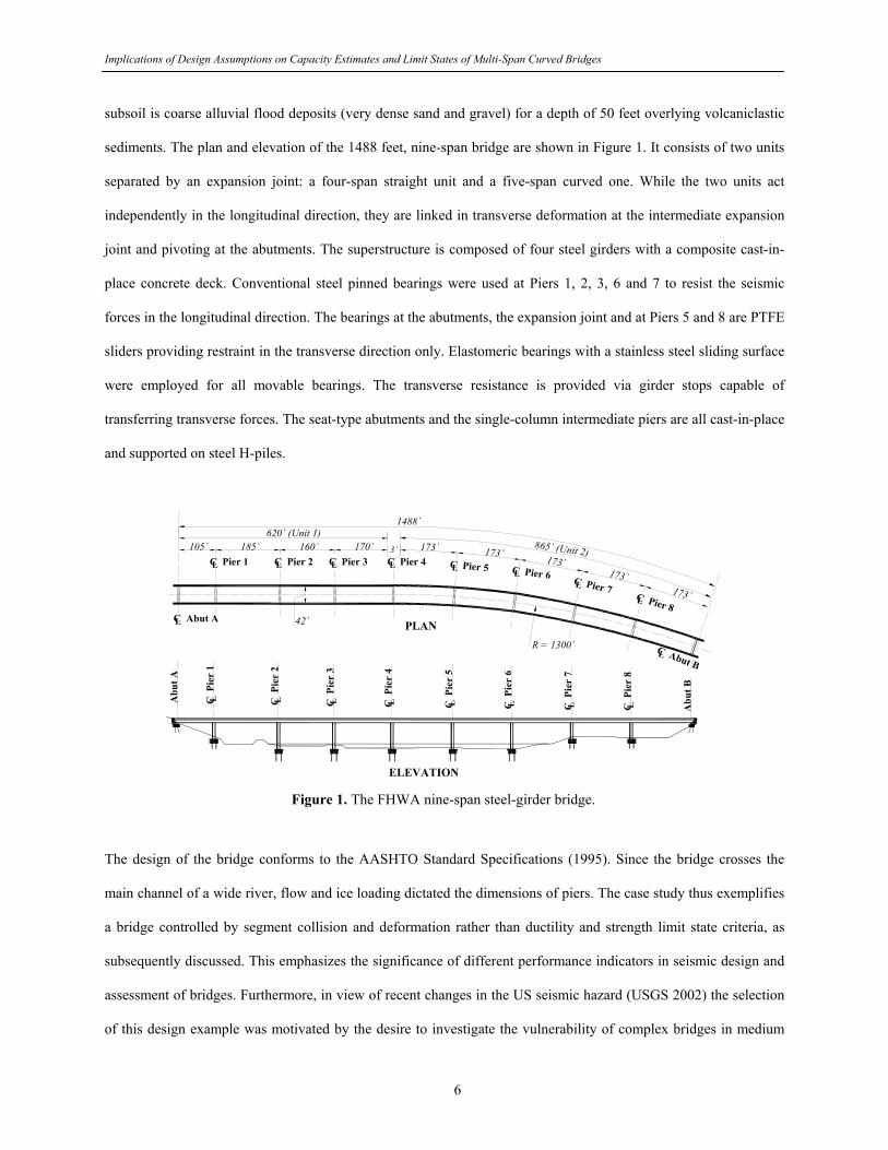
subsoil is coarse alluvial flood deposits (very dense sand and gravel) for a depth of 50 feet overlying volcaniclastic
sediments. The plan and elevation of the 1488 feet, nine-span bridge are shown in Figure 1. It consists of two units
separated by an expansion joint: a four-span straight unit and a five-span curved one. While the two units act
independently in the longitudinal direction, they are linked in transverse deformation at the intermediate expansion
joint and pivoting at the abutments. The superstructure is composed of four steel girders with a composite cast-in-
place concrete deck. Conventional steel pinned bearings were used at Piers 1, 2, 3, 6 and 7 to resist the seismic
forces in the longitudinal direction. The bearings at the abutments, the expansion joint and at Piers 5 and 8 are PTFE
sliders providing restraint in the transverse direction only. Elastomeric bearings with a stainless steel sliding surface
were employed for all movable bearings. The transverse resistance is provided via girder stops capable of
transferring transverse forces. The seat-type abutments and the single-column intermediate piers are all cast-in-place
and supported on steel H-piles.
105` 185` 160` 170` 173` 173` 173`173`
173`
C Pier 1L C Pier 2L C Pier 3L C Pier 4L C Pier 5L C Pier 6LC Pier 7L
C Pier 8L
C P
ier
1L C P
ier
2L C P
ier
3L C P
ier
4L C P
ier
5L C P
ier
6L C P
ier
7L C P
ier
8L Abu
t B
Abu
t A
PLAN
ELEVATION
620` (Unit 1)865` (Unit 2)3`
42`
R = 1300`
1488`
C Abut AL
C Abut BL
Figure 1. The FHWA nine-span steel-girder bridge.
The design of the bridge conforms to the AASHTO Standard Specifications (1995). Since the bridge crosses the
main channel of a wide river, flow and ice loading dictated the dimensions of piers. The case study thus exemplifies
a bridge controlled by segment collision and deformation rather than ductility and strength limit state criteria, as
subsequently discussed. This emphasizes the significance of different performance indicators in seismic design and
assessment of bridges. Furthermore, in view of recent changes in the US seismic hazard (USGS 2002) the selection
of this design example was motivated by the desire to investigate the vulnerability of complex bridges in medium
6

Implications of Design Assumptions on Capacity Estimates and Limit States of Multi-Span Curved Bridges
seismicity regions under higher levels of ground motions than the design earthquake. Further structural detailing
and geotechnical information are provided elsewhere (FHWA 1996).
STRUCTURAL AND FOUNDATION MODELING
Refined three-dimensional models of the entire bridge including foundations and soil effect were assembled for
elastic and inelastic analysis using SAP2000 (CSI 2003) and Zeus-NL (Elnashai et al. 2004), respectively. The
former modeling approach was employed for verifications of the Zeus-NL fiber modeling with the design before
executing the extensive inelastic analysis. Zeus-NL is mainly employed to estimate the capacities and demands from
inelastic pushover and response history analysis. The latter finite element analysis platform was developed and
thoroughly tested at Imperial College, UK, (Izzuddin and Elnashai 1989). The further development and verification
of the program with full scale test results have continued at University Illinois at Urbana-Champaign, USA, to
deliver a state-of-the-art inelastic analytical platform for static and dynamic analysis of steel, concrete and
composite structures (e.g. Jeong and Elnashai 2005).
In the detailed Zeus-NL modeling, each structural member is assembled using a number of cubic elasto-plastic
elements capable of representing the spread of inelasticity within the member cross-section and along the member
length via the fiber analysis approach. Sections are discretized to steel, confined and unconfined concrete fibers.
The stress-strain response at each fiber is monitored during the entire multi-step analysis. Gravity loads and mass
are distributed on the superstructure and along the height of piers. The employed distributed mass elements utilize
cubic shape function and account for both the translational and rotational inertia. Figures 2 and 3 depict the Zeus-
NL modeling approach of the superstructure and the entire bridge, respectively. Modeling of the pier and its
connection to the superstructure and the foundation system is described in Figure 3(c). A number of modeling
approaches were extensively investigated to select rational idealizations of superstructure, materials and bearings, as
discussed below.
Superstructure and Material Modeling
Modern seismic design philosophy of bridges relies on piers to dissipate energy rather than the superstructure,
which remains elastic under the design earthquake. Based on the conventional elastic theory, the superstructure is
7

Implications of Design Assumptions on Capacity Estimates and Limit States of Multi-Span Curved Bridges
modeled using three different cross sections; two hollow steel box sections equivalent to the four steel girders and a
RC rectangular cross section representing the deck. This conforms to the following two criteria: (i) equal sectional
areas and (ii) equivalent sectional moments of inertia and torsional constant. It is important to note that the total
torsional resistance of the employed closed steel cross sections is higher than those of the four steel girders.
However, the steel cross frames, employed to transfer the superstructure mass to piers, increase the torsional
resistance of the four steel girders. Thus, the adopted modeling approach realistically predicts the elastic behavior of
the superstructure. The elements idealizing the superstructure are located at the centeroid of the cross sections and
connected together using rigid arms, as shown in Figure 2.
RC rectangular cross section
Two hollow steel box cross sections
Shear studs 9`` deck
Top flangePL 2 x 18
WebPL 5/8
Bottom flangePL 2 x 18
Web 7`
RC deck X-section
Two steel box X-sections
Rigid arms
Node connnectingsuperstructure with pier
RC deck
Figure 2. Modeling approach of superstructure.
On the other hand, employing the characteristic material strength causes reduction in stiffness and elongation in
period. Hence, the characteristics values are only used for modeling the design configuration, while the more
realistic mean values are employed to assess the response of the as-built bridge. A normal distribution is adopted to
estimate the concrete compressive strength and steel yield strength. An average coefficient of variation (COV) of
12% for concrete, assuming average curing conditions and workmanship, and 6% for the steel, calculated from
previous experiments, are adopted (Rossetto and Elnashai 2005).
8

Implications of Design Assumptions on Capacity Estimates and Limit States of Multi-Span Curved Bridges
(a) Zeus-NL three-dimensional model
Pier No. 1 No. 2 No. 3 No. 4 No. 5 No. 6 No. 7 No. 8
PinPin Exp. Pin PinSlidePin Slide Exp.Exp.
(b) Modeling of bearings, gaps and foundation using joint elements
Superstructural elements connected here
Rigid arms
Pier elements
Foundationelements
1981
.2 m
m6.
5`30
48 m
m10
.0`
2590
.8 m
m8.
5`33
.0` =
100
58.4
mm
for
pi
er n
o. 1
, 7 a
nd 8
53.0
` = 1
0058
.4 m
m f
or
pier
no.
2 th
roug
h 6
1.5`
Springs represinting the soil are connected here
Superstructure deck elements
Rigid arms
Pier elements
Foundationelement
Superstructure steel box elements
Z
YX
TranslationalspringsRotationalsprings
(c) Modeling the pier and its foundation
Figure 3. ZeusNL model for the nine-span bridge
Foundation Modeling
The inertial soil-structure interaction is caused by deformation of the soil by the time varying inertia induced forces
developed in the footing. Based on the boring profile at the construction site, a soil type I was used in the design
(AASHTO 1995). This corresponds to stable deposits of sand and gravel less than 200 feet overlying rock. The
inertial soil-structure interaction is thus accounted for by restraining the pile caps with grounded springs
representing the stiffness of the bridge pile foundations, as depicted in Figures 3(c) for an intermediate pier. The
local coordinates of piers are used to idealize the foundation stiffness, which is calculated as follows:
9

Implications of Design Assumptions on Capacity Estimates and Limit States of Multi-Span Curved Bridges
• The axial and lateral stiffness of an individual pile were calculated.
• The pile group stiffnesses were obtained from combinations of individual piles.
• As a result to the high rigidity of the footing, contribution of the pile cap was neglected. This is justified by the
large relative stiffness of the foundation compared with the pier. Hence, the resulting demand on the
substructure will not change.
• Since the soil may not be in full contact with the pile caps, and to account for any liquefaction potential, the soil
contribution was conservatively disregarded in this modeling. Constructing of the bridge in the flood plain of a
large river supports this scenario due to loss of contact under the pile caps.
For the pile-bent abutment type used in the design, wing walls don’t contribute much to the transverse horizontal
resistance. Therefore, the transverse horizontal stiffness of the abutment is estimated using the translational stiffness
of the abutment pile group. In the longitudinal direction, the abutment embankment fill stiffness is estimated based
on the finding of a large-scale abutment testing (Maroney, 1995). The initial passive stiffness from this testing (11.5
kN/mm/m) is adjusted relative to the back-wall height (Caltrans, 2004). A maximum passive pressure was
recommended in the latter study, allowing the back-wall to break off in order to prevent inelasticity in the
foundation system. The stiffness in active action is assumed to be one fifth of the passive stiffness (Choi et al.,
2004). A bilinear elasto-plastic relationship is therefore adopted to model the longitudinal behavior of the abutment.
The vertical translation and torsional rotation of the abutment-superstructure connection are fully restrained, while
the rotation about the transverse and vertical axis is released. The springs and releases conform to the local
coordinate system of the abutments.
Bearings and Gaps Modeling
A zero frictional resistance is initially assumed at all sliding bearings with restrictions of movement at abutments.
Although this idealization is rather unrealistic, it was employed to be in consistency with the assumptions made in
the design phase. A rational estimation of the bearing frictional resistance is adopted afterwards in another
idealization to assess the behavior of the as-built structure. The PTFE-stainless steel movable bearings used in the
design have small friction coefficient at the low velocity rates (2-5%), while have higher friction under high seismic
deformation. For non-lubricated bearings, this coefficient at high velocities ranges from 5 to 15%, or even higher at
10

Implications of Design Assumptions on Capacity Estimates and Limit States of Multi-Span Curved Bridges
the low temperature (Constantinou et al., 1990; Priestley et al., 1996; Bondonet and Filiatrault, 1997). It was also
concluded in previous experimental studies that the coefficient of friction slightly decreases again under the high
velocities due to frictional heating. The bridge investigated in the current study is assessed under increasing levels
of input ground motion. Accordingly, it was decided to use a 10% friction coefficient for the analytical model used
to assess the as-built behavior of the bridge.
Two modeling approaches were investigated to idealize the impact stiffness. In the first approach, the pounding is
represented by a nonlinear spring (Hertz model). The impact stiffness increases in this approach from 2.92E6 MPa
to 4.38E6 MPa at a penetration of 1.27 mm, and increases again at 2.54 mm to 8.76E6 MPa (e.g. Choi et al., 2004).
These values are controlled to ensure that the penetration of pounding is less than 2.54 mm (0.1 in). Muthukumar
and DesRoches (2006) concluded that this modeling approach is sufficient for the impact simulation at a PGA of
0.1-0.3g, which is the intensity range investigated in the present study. Results obtained from this idealization were
compared with a more simplified linear spring model employing the maximum impact stiffness (Ki) of 8.76E6 MPa.
It was concluded that the former model has insignificant effect on the response at the design earthquake, while it has
a marginal effect at twice the design earthquake, compared with the simplified linear model. It was therefore
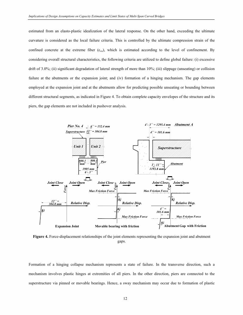
decided to use the simplified approach to model the impact stiffness. Figure 4 shows the force versus relative
displacement relationships of the joint elements representing the expansion joint, movable bearings and structural
gaps. In this modeling, a positive relative displacement corresponds to an opening of the joint gap and a negative
displacement corresponds to a closing of the gap. When the gap at the abutment and at the expansion joint
undergoes a relative movement in the negative direction (joint close) exceeding the gap width, the joint element
begins resisting further opening (collisions). It is clear that slippage takes place in the as-built modeling when the
applied force reaches the maximum friction developed on the contact plane of the bearing.
LIMIT STATES AND ANALYSIS PROCEDURE
The performance criteria for yield and collapse are classified into two groups (Mwafy and Elnashai 2001 and 2002):
local (member level) and global (structure level) criteria. Member yield is considered when the strain in the main
longitudinal tensile reinforcement exceeds the steel yield strain. The yield limit state on the structure level is
11
Implications of Design Assumptions on Capacity Estimates and Limit States of Multi-Span Curved Bridges
estimated from an elasto-plastic idealization of the lateral response. On the other hand, exceeding the ultimate
curvature is considered as the local failure criteria. This is controlled by the ultimate compression strain of the
confined concrete at the extreme fiber (εcu), which is estimated according to the level of confinement. By
considering overall structural characteristics, the following criteria are utilized to define global failure: (i) excessive
drift of 3.0%; (ii) significant degradation of lateral strength of more than 10%; (iii) slippage (unseating) or collision
failure at the abutments or the expansion joint; and (iv) formation of a hinging mechanism. The gap elements
employed at the expansion joint and at the abutments allow for predicting possible unseating or bounding between
different structural segments, as indicated in Figure 4. To obtain complete capacity envelopes of the structure and its
piers, the gap elements are not included in pushover analysis.
Pier No. 4Superstructure
Pier
6`` = 152.4 mm
1905 mm
800.1
6`- 3``
12`` = 304.8 mm
800.1mm mm
Unit 1 Unit 2
4`- 3`` = 1295.4 mm
3`- 11`` =
4`` = 101.6 mm
Abutment
Abutment A
1193.8 mm
Superstructure
Relative Disp.
For
ce
304.8 mm Relative Disp.
For
ce
12`` =
Max Friction Force
Max Friction Force
Joint OpenJoint CloseJoint OpenJoint Close
Ki
Kj
Expansion Joint
Kj
Movable bearing with friction
Relative Disp.
For
ce
Max Friction Force
Max Friction Force
Abutment Gab with Friction
Joint OpenJoint Close
Ki
Kj
101.6 mm4`` =
Gap
Figure 4. Force-displacement relationships of the joint elements representing the expansion joint and abutment
gaps.
Formation of a hinging collapse mechanism represents a state of failure. In the transverse direction, such a
mechanism involves plastic hinges at extremities of all piers. In the other direction, piers are connected to the
superstructure via pinned or movable bearings. Hence, a sway mechanism may occur due to formation of plastic
12
Implications of Design Assumptions on Capacity Estimates and Limit States of Multi-Span Curved Bridges
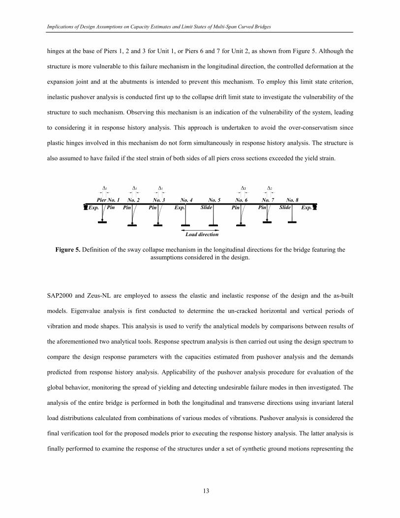
hinges at the base of Piers 1, 2 and 3 for Unit 1, or Piers 6 and 7 for Unit 2, as shown from Figure 5. Although the
structure is more vulnerable to this failure mechanism in the longitudinal direction, the controlled deformation at the
expansion joint and at the abutments is intended to prevent this mechanism. To employ this limit state criterion,
inelastic pushover analysis is conducted first up to the collapse drift limit state to investigate the vulnerability of the
structure to such mechanism. Observing this mechanism is an indication of the vulnerability of the system, leading
to considering it in response history analysis. This approach is undertaken to avoid the over-conservatism since
plastic hinges involved in this mechanism do not form simultaneously in response history analysis. The structure is
also assumed to have failed if the steel strain of both sides of all piers cross sections exceeded the yield strain.
Pier No. 1 No. 2 No. 3 No. 4 No. 5 No. 6 No. 7 No. 8
Load direction
PinPin Exp. Pin PinSlidePin Slide Exp.Exp.
Δ1
Δ1
Δ1
Δ2
Δ2
Figure 5. Definition of the sway collapse mechanism in the longitudinal directions for the bridge featuring the assumptions considered in the design.
SAP2000 and Zeus-NL are employed to assess the elastic and inelastic response of the design and the as-built
models. Eigenvalue analysis is first conducted to determine the un-cracked horizontal and vertical periods of
vibration and mode shapes. This analysis is used to verify the analytical models by comparisons between results of
the aforementioned two analytical tools. Response spectrum analysis is then carried out using the design spectrum to
compare the design response parameters with the capacities estimated from pushover analysis and the demands
predicted from response history analysis. Applicability of the pushover analysis procedure for evaluation of the
global behavior, monitoring the spread of yielding and detecting undesirable failure modes in then investigated. The
analysis of the entire bridge is performed in both the longitudinal and transverse directions using invariant lateral
load distributions calculated from combinations of various modes of vibrations. Pushover analysis is considered the
final verification tool for the proposed models prior to executing the response history analysis. The latter analysis is
finally performed to examine the response of the structures under a set of synthetic ground motions representing the
13

Implications of Design Assumptions on Capacity Estimates and Limit States of Multi-Span Curved Bridges
site. The comprehensive results of response history analyses are presented in Part II of this study and by Mwafy et
al. (2006-a), while other analysis results are discussed below.
DYNAMIC CHARACTERISTICS AND MODEL VERIFICATION
Comparisons between the modes of vibration of the design configuration obtained from SAP2000 and Zeus-NL are
given in Figures 6 and 7(a), respectively. It is clear that the mode shapes of both analytical platforms are
comparable. The first and second mode shapes are in the longitudinal direction for unit 2 and 1, respectively. The
predominant mode in the transverse direction is the third mode. For this modeling approach, which disregards
friction, it is confirmed that the two units of the structure independently vibrate in the longitudinal direction. The
stiffness of Unit 1 is higher than Unit 2 in this direction as a result of the participation of three piers in resisting the
inertia forces transmitted from the superstructure. This is unlike the case of Unit 2 since two piers only resist the
longitudinal seismic forces.
2nd Mode
1st Mode
Fund. period of unit 2 = 1.52 sec
Fund. period of unit 1 = 1.21 sec
Predominant period in the transverse
direction = 0.80 sec3rd Mode
Figure 6. SAP2000 dynamic characteristics of the bridge featuring the assumptions considered in the design.
The periods obtained from Zeus-NL are slightly lower than those from SAP2000 due to the difference between the
superstructure modeling approach adopted in the two programs. Following the design assumptions, the SAP2000
model employs an equivalent RC cross section, in which the cross-sectional area of the steel girders was
14
Implications of Design Assumptions on Capacity Estimates and Limit States of Multi-Span Curved Bridges
transformed to a concrete section using the modular ratio. Also the concrete deck was only considered to estimate
the torsional rigidity. Since this assumption underestimates the superstructure geometrical properties, Zeus-NL
modeling employs a more rational idealization, as discussed earlier (refer to Figure 2). Therefore, Zeus-NL results
are in principle more realistic compared with those obtained from the SAP2000.
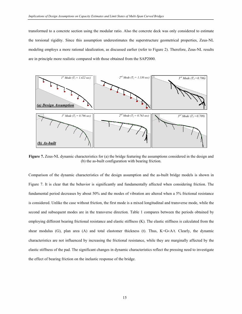
(a) 1st Mode (T1 = 1.422 sec) (b) 2nd Mode (T2 = 1.130 sec) (c) 3rd M
(a) 1st Mode (T1 = 0.796 sec) (b) 2nd Mode (T2 = 0.763 sec) (c) 3rd Mode
3rd Mode (T3 =0.786)
3rd Mode (T3 =0.709)
(a) Design Assumption
(b) As-built
Figure 7. Zeus-NL dynamic characteristics for (a) the bridge featuring the assumptions considered in the design and
(b) the as-built configuration with bearing friction.
Comparison of the dynamic characteristics of the design assumption and the as-built bridge models is shown in
Figure 7. It is clear that the behavior is significantly and fundamentally affected when considering friction. The
fundamental period decreases by about 50% and the modes of vibration are altered when a 5% frictional resistance
is considered. Unlike the case without friction, the first mode is a mixed longitudinal and transverse mode, while the
second and subsequent modes are in the transverse direction. Table 1 compares between the periods obtained by
employing different bearing frictional resistance and elastic stiffness (K). The elastic stiffness is calculated from the
shear modulus (G), plan area (A) and total elastomer thickness (t). Thus, K=G×A/t. Clearly, the dynamic
characteristics are not influenced by increasing the frictional resistance, while they are marginally affected by the
elastic stiffness of the pad. The significant changes in dynamic characteristics reflect the pressing need to investigate
the effect of bearing friction on the inelastic response of the bridge.
15

Implications of Design Assumptions on Capacity Estimates and Limit States of Multi-Span Curved Bridges
Response spectrum analysis is performed using the design response spectrum (AASHTO Standard Specifications
1995). Thirty-six modes of vibration are employed to reach a 90% mass participation in the two principle directions.
The Complete Quadratic Combination (CQC) method, which accounts for the coupling between modes, is used to
combine the modal forces and displacement. The demands imposed on the bridge from this analysis are summarized
in Table 2. The results are similar to those used in the design, which lend extra weight to the analytical models
developed in the current study and allows for comparisons between the design parameters obtained from SAP2000
elastic analysis and Zeus-NL inelastic pushover and response history procedures.
Table 1: Comparison between periods of vibration of different analytical modeling. Zeus-NL as-built configurationb Zeus-NL
design conf. a 5% Friction (stiffness = K)
30% Friction (stiffness = K)
30% Friction (stiffness = 6K)
Period
SAP2000 design conf.a
(sec.) Period (sec.) Diff (%) Period
(sec.) Diff (%) Period (sec.) Diff (%) Period
(sec.) Diff (%)
T1 1.518 1.422 6.3 0.796 47.6 0.796 47.6 0.764 49.7 T2 1.207 1.130 6.4 0.763 36.8 0.763 36.8 0.709 41.3 T3 0.802 0.786 2.0 0.709 11.6 0.709 11.6 0.659 17.8 T4 0.748 0.732 2.1 0.651 13.0 0.651 13.0 0.608 18.7 T5 0.748 0.699 6.6 0.609 18.6 0.609 18.6 0.594 20.6
a: Design configuration: Friction is neglected and characteristics values of material strength are used b: As-built configuration: Bearing friction and mean values of material strength are considered K: The elastic stiffness of the elastomeric pad. Table 2: Seismic demands of the design configuration from response spectrum analysis.
Longitudinal Responsea Transverse Responsea Support
Shear (kN) Disp. (mm) Shear (kN) Disp. (mm) Pier No.1 3185 62 1721 17 Pier No.2 1472 62 2260 33 Pier No.3 1472 62 2811 42
Pier No.4 1130 63-82 (for Unit 1 & 2) 3350 50
Pier No.5 1148 81 3123 45 Pier No.6 1837 78 2415 35 Pier No.7 4057 74 2411 24 Pier No.8 1383 69 2015 20
Demands are at the pier base (forces) and at the pier top (displacements). a: Seismic load and measured demands are either in the longitudinal or transverse direction. Shortcomings of the design modeling assumptions are exemplified from the results of response spectrum analysis,
particularly in the longitudinal direction. High base shear demands are attracted to Pier 1 and 7. Since these short
piers are provided with pined bearings, they attract higher seismic demands due to their higher stiffness. Pier 8 does
16

Implications of Design Assumptions on Capacity Estimates and Limit States of Multi-Span Curved Bridges
not effectively participate in resisting the lateral forces due to neglecting the PTFE slider friction in the design
modeling. The non-uniform distribution of displacement demands between Unit 1 and 2 is also clear since both
units are uncoupled and vibrate independently.
CAPACITY ESTIMATES AND PRIORITIZING LIMIT STATES
Modern seismic design codes and guidelines (e.g. EC8 2004; FEMA 450 2003) adopt static pushover analysis as a
design and assessment tool. The sequence of yielding and failure as well as the progress of the overall capacity
curve of the structure are traced in the current study for both the design and the as-built configurations. This
identifies potential structural deficiencies, enables estimation of the lateral capacity and provides insight into the
limit state criteria required for response history analysis. To represent the distribution of inertia forces imposed on
the bridge, lateral force profiles are calculated as a combination of load distributions obtained from eigenvalue
analysis. A number of modes of vibration in the longitudinal and transverse directions are selected based on their
mass participation to calculate the load patterns in the two principle directions. The gaps at the abutments and the
expansion joints (refer to Figures 4) are not modeled in this incremental analysis to allow reaching the ultimate
capacity and obtain complete capacity envelopes of the structure and its piers. Accordingly, the adopted target
displacement corresponds to the drift collapse limit state.
Analysis of Individual Piers
The height of Piers 1, 7 and 8 is 50 feet, while it is 70 feet for other intermediate piers, as shown from Figure 3.
Pushover analysis is thus carried out on each of the two pier configurations in the longitudinal and transverse
directions to estimate their lateral capacity. In this analysis, the pier is free at top and the foundation is modeled as
discussed earlier. The cross section at the base of the pier is 6.25 × 20 feet. This justifies the higher capacity in the
transverse direction (400%) compared with the longitudinal one, as shown in Figure 8. Clearly, the stiffness and
capacity of the shorter pier is higher than its counterpart. The increase in capacity when the mean material strength
is used in analysis is about 9% compared with the case employing characteristic strengths.
17
Implications of Design Assumptions on Capacity Estimates and Limit States of Multi-Span Curved Bridges
0
2000
4000
6000
8000
10000
12000
14000
0 100 200 300 400 500 600Top Disp. - mm
Bas
e Sh
ear -
kN Charact. Strength
Mean Strength
1% D
rift
2% D
rift
3% D
rift
Pier 1Z-dir.
X-dir.
0 100 200 300 400 500 600Top Disp. - mm
1% D
rift
2% D
rift
3% D
rift
Pier 2 Pier No. 1 Pier No. 2
Z
Y
XZ-dir.
X-dir.
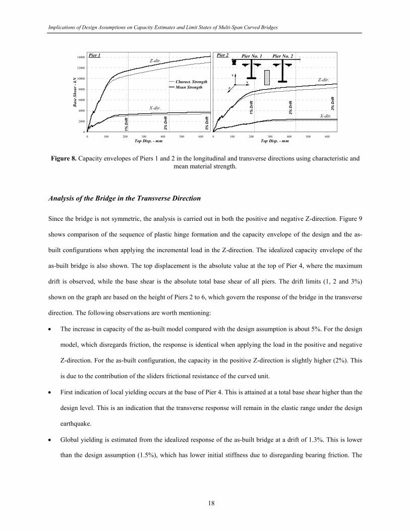
Figure 8. Capacity envelopes of Piers 1 and 2 in the longitudinal and transverse directions using characteristic and mean material strength.
Analysis of the Bridge in the Transverse Direction
Since the bridge is not symmetric, the analysis is carried out in both the positive and negative Z-direction. Figure 9
shows comparison of the sequence of plastic hinge formation and the capacity envelope of the design and the as-
built configurations when applying the incremental load in the Z-direction. The idealized capacity envelope of the
as-built bridge is also shown. The top displacement is the absolute value at the top of Pier 4, where the maximum
drift is observed, while the base shear is the absolute total base shear of all piers. The drift limits (1, 2 and 3%)
shown on the graph are based on the height of Piers 2 to 6, which govern the response of the bridge in the transverse
direction. The following observations are worth mentioning:
• The increase in capacity of the as-built model compared with the design assumption is about 5%. For the design
model, which disregards friction, the response is identical when applying the load in the positive and negative
Z-direction. For the as-built configuration, the capacity in the positive Z-direction is slightly higher (2%). This
is due to the contribution of the sliders frictional resistance of the curved unit.
• First indication of local yielding occurs at the base of Pier 4. This is attained at a total base shear higher than the
design level. This is an indication that the transverse response will remain in the elastic range under the design
earthquake.
• Global yielding is estimated from the idealized response of the as-built bridge at a drift of 1.3%. This is lower
than the design assumption (1.5%), which has lower initial stiffness due to disregarding bearing friction. The
18

Implications of Design Assumptions on Capacity Estimates and Limit States of Multi-Span Curved Bridges
ultimate capacity is significantly higher than the design shear force. The observed overstrength (Ωd = actual
/design strength = 2.4) reflects the reliability of the bridge in this direction (Elnashai and Mwafy 2002).
• No degradation in lateral strength or sway mechanism are observed up to the drift collapse limit state. The
pertinent performance indicators in this direction are therefore: (i) the segment collision at abutments; (ii) the
drift (1.5% for yielding and 3.0% for collapse); and (iii) member criteria (local yielding and ultimate curvature).
As a result of the curvature of the bridge, the longitudinal collision at abutments is the controlling collapse
criterion even when applying the load in the transverse direction.
1 23
457
69
10
Pier No. 1 No. 2 No. 3 No. 4 No. 5 No. 6 No. 7 No. 8
1 73
284
956
811
12Design
As-built
Unit 1 Unit 2
0
10000
20000
30000
40000
50000
60000
0 100 200 300 400 500 600Top Disp. - mm
Base
She
ar -
kN
1% D
rift
2% D
rift
3% D
rift
Design
As-builtStrength at 3% drift (σ max )
75% (σ max )
Idialized response
First indication of local yielding
Design strength
Direction of lateral loads
Direction of lateral loads
Figure 9. Mapping of sequence of plastic hinge formation and capacity envelope of the design and the as-built configurations in transverse direction.
Analysis of the Bridge in Longitudinal Direction
Longitudinal movement of the superstructure is controlled by the bearing friction, which follows the modeling
approach explained earlier for the design assumption and the as-built configurations. Since the bridge in this
direction consists of two units with distinct characteristics, the analysis is performed separately for each unit. For
Unit 1, the incremental lateral load is applied in the negative X-direction, while it is in the positive X-direction for
Unit 2. This is undertaken to avoid the collision between the two units, as indicated in Figure 10. Comparisons of
19
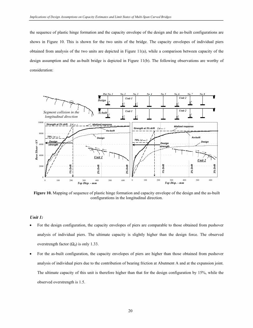
Implications of Design Assumptions on Capacity Estimates and Limit States of Multi-Span Curved Bridges
the sequence of plastic hinge formation and the capacity envelope of the design and the as-built configurations are
shows in Figure 10. This is shown for the two units of the bridge. The capacity envelopes of individual piers
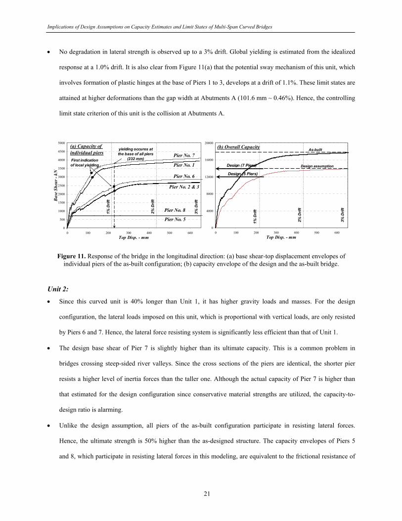
obtained from analysis of the two units are depicted in Figure 11(a), while a comparison between capacity of the
design assumption and the as-built bridge is depicted in Figure 11(b). The following observations are worthy of
consideration:
25
3
Pier No. 1 No. 2 No. 3 No. 4 No. 5 No. 6 No. 7 No. 8
614
35
461
2
23 1
4
24 1
3
Design
As-built
Unit 1 Unit 2
Unit 1 Unit 2
Segment collision in the longitudinal direction
0
2000
4000
6000
8000
10000
0 100 200 300 400 500 600Top Disp. - mm
Bas
e Sh
ear -
kN
1% D
rift
2% D
rift
3% D
rift
Unit 1
As-built
Design
Strength at 3% drift ( σ max )
75% (σ max )
Idialized response
Design strength
0 100 200 300 400 500 600Top Disp. - mm
1% D
rift
2% D
rift
3% D
rift
Unit 2
Strength at 3% drift ( σ max )
75% (σ max )As-built
Idialized response
Design strength
Design
Figure 10. Mapping of sequence of plastic hinge formation and capacity envelope of the design and the as-built configurations in the longitudinal direction.
Unit 1:
• For the design configuration, the capacity envelopes of piers are comparable to those obtained from pushover
analysis of individual piers. The ultimate capacity is slightly higher than the design force. The observed
overstrength factor (Ωd) is only 1.33.
• For the as-built configuration, the capacity envelopes of piers are higher than those obtained from pushover
analysis of individual piers due to the contribution of bearing friction at Abutment A and at the expansion joint.
The ultimate capacity of this unit is therefore higher than that for the design configuration by 15%, while the
observed overstrength is 1.5.
20
Implications of Design Assumptions on Capacity Estimates and Limit States of Multi-Span Curved Bridges
• No degradation in lateral strength is observed up to a 3% drift. Global yielding is estimated from the idealized
response at a 1.0% drift. It is also clear from Figure 11(a) that the potential sway mechanism of this unit, which
involves formation of plastic hinges at the base of Piers 1 to 3, develops at a drift of 1.1%. These limit states are
attained at higher deformations than the gap width at Abutments A (101.6 mm ~ 0.46%). Hence, the controlling
limit state criterion of this unit is the collision at Abutments A.
0
500
1000
1500
2000
2500
3000
3500
4000
4500
5000
0 100 200 300 400 500 600Top Disp. - mm
Bas
e Sh
ear -
kN
1% D
rift
2% D
rift
3% D
rift
Pier No. 6
Pier No. 7First indication of local yielding
yielding occures at the base of all piers
(232 mm)
Pier No. 8
Pier No. 5
Pier No. 1
Pier No. 2 & 3
(a) Capacity of individual piers
0
4000
8000
12000
16000
20000
0 100 200 300 400 500 600Top Disp. - mm
1% D
rift
2% D
rift
3% D
rift
(b) Overall Capacity
Design (7 Piers)
Design (5 Piers)
Design assumption
As-built
Figure 11. Response of the bridge in the longitudinal direction: (a) base shear-top displacement envelopes of
individual piers of the as-built configuration; (b) capacity envelope of the design and the as-built bridge.
Unit 2:
• Since this curved unit is 40% longer than Unit 1, it has higher gravity loads and masses. For the design
configuration, the lateral loads imposed on this unit, which is proportional with vertical loads, are only resisted
by Piers 6 and 7. Hence, the lateral force resisting system is significantly less efficient than that of Unit 1.
• The design base shear of Pier 7 is slightly higher than its ultimate capacity. This is a common problem in
bridges crossing steep-sided river valleys. Since the cross sections of the piers are identical, the shorter pier
resists a higher level of inertia forces than the taller one. Although the actual capacity of Pier 7 is higher than
that estimated for the design configuration since conservative material strengths are utilized, the capacity-to-
design ratio is alarming.
• Unlike the design assumption, all piers of the as-built configuration participate in resisting lateral forces.
Hence, the ultimate strength is 50% higher than the as-designed structure. The capacity envelopes of Piers 5
and 8, which participate in resisting lateral forces in this modeling, are equivalent to the frictional resistance of
21

Implications of Design Assumptions on Capacity Estimates and Limit States of Multi-Span Curved Bridges
the PTFE bearings. The capacity of Piers 6 and 7 is higher than that obtained from individual piers.
Overstrength is 1.4, which represents an observable enhancement compared with the design configuration.
• No degradation in lateral strength is observed up to a 3% drift. It is also clear from Figure 11(a) that the sway
mechanism, which involves formation of plastic hinges at the base of Piers 6 and 7, develops at a drift of 1.1%.
Global yielding is estimated at a drift of 0.8%. These limit states are attained at higher deformations than the gap
width at Abutments B. Hence, the limit state that controls the response of this unit is the collision at Abutment B.
Entire Bridge:
• The overall capacity increases by 30% as a result of the added resistance from the movable bearings at
intermediate piers and at abutments.
• In the transverse direction, the pier stiffness is significantly higher than the longitudinal direction and all piers
fully participate in resisting the lateral forces. Therefore, the lateral capacity is considerably higher than the
longitudinal direction (240% and 180% for the design and the as-built configuration, respectively).
• The drift at local and global yielding is higher than the gap width at the two abutments. The controlled
deformation at abutments prevents undesirable modes of failure since the response is in the elastic range. The
collision at abutments is thus the governing performance criterion in the longitudinal direction.
CONCLUSIONS
A multi-span curved bridge was selected to investigate the significance of frequently-used design assumptions on
seismic integrity of highway bridges. As opposed to undertaking extensive parametric studies where the parameters
are varied not necessarily according to design specifications, this work focused in intricate detailing of one case of a
realistic, office-designed and checked complex bridge. Refined three-dimensional modeling approaches were
verified and employed to compare between the elastic and inelastic behavior of the design and the as-built
configurations. The adopted methodology and results of the comprehensive analysis performed to estimate the
dynamic characteristics, capacities and limit state criteria were presented. The following conclusions were drawn:
• The main modeling parameters affecting the dynamics characteristics were: bearing support modeling, material
representation and superstructure idealization. The modes of vibration were significantly and fundamentally
22

Implications of Design Assumptions on Capacity Estimates and Limit States of Multi-Span Curved Bridges
different and the fundamental period decreased by 50% when the bearing frictional resistance was accounted
for. Without friction the two units of the bridge vibrated independently in the longitudinal direction, while
friction linked them together at the expansion joint. Due to the curvature of the bridge and the non-uniform
distribution of stiffness and mass, higher modes notably contributed to seismic response.
• In the transverse direction, the response was less affected by friction due to restraining the PTFE sliders by
girder stops. The capacity increase of the as-built model was 5%. Overstrength was 2.4 and first yielding was
attained at a base shear higher than the design value, confirming the high margin of safety and the anticipated
elastic response under the design earthquake. Pushover analysis confirmed that the collision at abutments was
the controlling performance criterion even when seismic loads were applied in the transverse direction of the
curved bridge.
• To avoid collision between the two units of the bridge, pushover analysis was performed independently for
Unit 1 and 2 by applying the incremental load in two opposite directions. For Unit 1, overstrength of the as-
built configuration increased from 1.33 to 1.5. Global yielding and the sway mechanism were estimated at a
drift higher than the gap width at the abutments. The controlling limit state criterion of Unit 1 was therefore the
collision at Abutments A.
• For the design configuration, Unit 2 was less efficient in the longitudinal direction than Unit 1 due to excluding
the PTFE piers from resisting lateral loads. As the bridge crosses a steep-sided river valley, response of a short
stiff pier was critical due to the high attracted inertia forces. Overstrength of Unit 2 was almost unity,
confirming its high vulnerability. For the as-built configuration, all piers participated in resisting lateral forces.
Hence, the capacity was 50% higher than the as-designed structure. For both configurations, global yielding
and the sway mechanism developed at a drift akin to that observed for Unit 1. Hence, the controlling limit state
for Unit 2 is the collision at Abutments B. Pushover analysis confirmed that the superstructure-abutment zones
controlled the response in the two principle directions of the curved bridge.
The study emphasizes the significance of pushover analysis procedures in verification of analytical modeling,
identifying potential structural deficiencies, estimating capacity and providing insight into the limit states of
complex bridges. The major difference between modeling the bridge as-designed and as-built was the inclusion of
bearing friction. The dynamic characteristics changed fundamentally and the capacity increased significantly when
23

Implications of Design Assumptions on Capacity Estimates and Limit States of Multi-Span Curved Bridges
friction was included, using a conservative friction coefficient. The latter change led to an adverse impact on
seismic demands due to the significant reduction in the periods of vibration. Conventional design assumptions, such
as zero friction on intermediate piers, may therefore lead to non-conservative designs. This is confirmed from
comparisons of capacities and demands predicted from response history analysis.
ACKNOWLEDGMENTS
This study was funded by the US Federal Highway Administration (FHWA) through the Mid-America Earthquake
Center (MAE), University of Illinois at Urbana-Champaign, USA. The MAE Center is an Engineering Research
Center funded by the National Science Foundation under cooperative agreement reference EEC 97-01785.
24

Implications of Design Assumptions on Capacity Estimates and Limit States of Multi-Span Curved Bridges
REFERENCES
1. AASHTO Standard Specifications (1995). Standard specifications for highway bridges, 15th Ed., American
Association of State Highway and Transportation Officials, Washington, D.C.
2. Antoniou, S., and Pinho, R. (2004). “Advantages and limitations of adaptive and non-adaptive force-based
pushover procedures.” J. of Earthquake Engineering, 8(4), 497-522.
3. Bondonet, G., and Filiatrault, A. (1997). “Frictional Response of PTFE Sliding Bearings at High Frequencies.”
J. of Bridge Engineering, 2(4), pp. 139-148.
4. Caltrans (2004). Caltrans Seismic Design Criteria. California Department of Transportation, Sacramento, CA.
5. Choi, E., DesRoches, R., and Nielson B. (2004). “Seismic fragility of typical bridges in moderate seismic
zones.” Eng. Structures, 26, 187–199.
6. Constantinou, M. C., Mokha, A., and Reinhorn, A. M. (1990). “Teflon bearings in base isolation II: Modeling.”
J. of Structural Engineering, 116(2), 455–474.
7. CSI (2003). SAP2000 – Structural analysis program, Computers and Structures, Inc., Berkeley, California.
8. EC8 (2004). Eurocode 8: Design of structures for earthquake resistance - Part 1: General rules, seismic
actions and rules for buildings, and Part 2: Bridges, CEN, European Committee for Standardization, Brussels.
9. Elnashai, A.S. (2001). “Advanced inelastic static (pushover) analysis for earthquake applications.” J. of
Structural Engineering and Mechanics, 12(1), 51-69.
10. Elnashai, A.S. (2002). “Do we really need inelastic dynamic analysis?.” J. of Earthquake Engineering,
6(Special Issue 1), 123-130.
11. Elnashai, A.S., and Mwafy, A.M. (2002). “Overstrength and force reduction factors of multistorey reinforced-
concrete buildings.” The Structural Design of Tall Buildings, 11(5), 329–351.
12. Elnashai, A.S., Papanikolaou, V., and Lee, D. (2004). Zeus-NL - a system for inelastic analysis of structures,
User Manual, Mid-America Earthquake Center, Civil and Environmental Engineering Department, Univ. of
Illinois at Urbana-Champaign, Urbana, IL.
13. FEMA (2003). NEHRP recommended provisions for seismic regulations for new buildings and other structures
(FEMA 450), Federal Emergency Management Agency, Washington, D.C.
25

Implications of Design Assumptions on Capacity Estimates and Limit States of Multi-Span Curved Bridges
14. Izzuddin, B.A., and Elnashai, A.S. (1989). ADAPTIC – A program for adaptive large displacement
elastoplastic dynamic analysis of steel, concrete and composite frames, ESEE Research Report No. 89/7,
Imperial College, Univ. of London, UK.
15. FHWA (1996). Seismic design of bridges – Design example No. 5 – Nine-span viaduct steel girder bridge, US
Department of Transportation, Publication No. FHWA-SA-97-010.
16. Jeong, S.-H., and Elnashai, A.S. (2005). “Analytical assessment of an irregular RC frame for full-scale 3d
pseudo-dynamic testing - Part I: Analytical model verification.” J. of Earthquake Engineering, 9(1), 95-128.
17. Lu, Z., Ge, H., and Usami, T. (2004). “Applicability of pushover analysis-based seismic performance
evaluation procedure for steel arch bridges.” Engineering structures, 26(13), 1957–1977.
18. Maroney, B.H. (1995). Large scale bridge abutment tests to determine stiffness and ultimate strength under
seismic loading, PhD Thesis, University of California, Davis.
19. Muthukumar, S., and DesRoches, R. (2006). “A Hertz contact model with non-linear damping for pounding
simulation,” Earthquake Eng. Struct. Dyn., 35(7), 811-828.
20. Mwafy, A.M., Elnashai, A.S., and Yen, W-H. (2006-a). “Implications of design assumptions on capacity
estimates and demand predictions of multi-span curved bridges”, ASCE Journal of Bridge Engineering, In
Press.
21. Mwafy, A.M., Elnashai, A.S., Sigbjörnsson, R., and Salama, A. (2006-b). “Significance of severe distant and
moderate close earthquakes on design and behavior of tall buildings.” The Structural Design of Tall and
Special Buildings, Vol. 15(4), 391-416.
22. Mwafy, A.M., and Elnashai, A.S. (2002). “Calibration of force reduction factors of RC buildings.” J. of
Earthquake Engineering, 6(2), 239-273.
23. Mwafy, A.M., and Elnashai, A.S. (2001). “Static pushover versus dynamic collapse analysis of RC buildings.”
Engineering Structures, 23(5), 407-424.
24. Priestley, M.J.N., Seible, F., and Calvi, G.M. (1996). Seismic design and retrofit of bridges, Wiley, New York.
25. Rossetto T., and Elnashai, A.S. (2005). “A new analytical procedure for the derivation of displacement-based
vulnerability curves for populations of RC structures.” Engineering Structures, 27(3), 397–409.
26. USGS (2002). “Seismic hazard maps for the conterminous U.S. for 2002.” U.S. Geological Survey Earthquake
Hazards Program, <http://earthquake.usgs.gov> (Jan. 31, 06).
27. Zheng, Y., Usami, T., and Ge, H. (2003). “Seismic response predictions of multi-span steel bridges through
pushover analysis.” Earthquake Engineering and Structural Dynamics, 32(8), 1259–1274.
26
Assessment of Seismic Integrity of Multi-Span Curved Bridges in Mid-America
Part II: Comparative Assessment of the Designed and As-Built Simulations of Complex Bridges Subjected to Increasing Earthquake Intensities
by
A.M. Mwafy and A.S. Elnashai
Mid-America Earthquake Center Civil and Environmental Engineering Department
University of Illinois at Urbana-Champaign, IL, USA
April 2007
This research is supported by the Mid-America Earthquake Center under National Science Foundation Grant EEC-9701785

Comparative Assessment of the Designed and As-Built Simulations of Complex Bridges Subjected to Increasing Earthquake Intensities
TABLE OF CONTENTS
SUMMARY.....................................................................................................................................3
INTRODUCTION ...........................................................................................................................4
INGREDIENTS OF THE ASSESSMENT STUDY .......................................................................5
Structural Modeling and Performance Indicators............................................................................... 5 Input Ground Motions ........................................................................................................................ 6
SELECTION OF DYNAMIC ANALYSIS PARAMETERS .........................................................8
DEMAND PREDICTIONS AT THE DESIGN EARTHQUAKE ................................................10
Response in Transverse Direction .................................................................................................... 10 Response in Longitudinal Direction................................................................................................. 14
DEMAND PREDICTIONS AT TWICE THE DESIGN EARTHQUAKE ..................................19
Response in the Transverse Direction .............................................................................................. 19 Response in the Longitudinal Direction ........................................................................................... 20
CONCLUSIONS............................................................................................................................22
ACKNOWLEDGMENTS .............................................................................................................24
REFERENCES ..............................................................................................................................25
2

Comparative Assessment of the Designed and As-Built Simulations of Complex Bridges Subjected to Increasing Earthquake Intensities
SUMMARY
The significance of simplified design assumptions on seismic integrity of highway bridges is investigated in this
study by comparisons of the ‘as-built’ and the ‘as-designed’ seismic response of a nine-span curved bridge at the
design and twice the design earthquake intensity. The prototype bridge was selected from the inventory of the
Federal Highway Administration (FHWA) concept designs to represent a US typical design of multi-span curved
bridges with superstructure-pier bearings. Extensive inelastic response history analyses are performed using verified
three-dimensional fiber idealizations to predict the capacity-to-demand ratios of the bridge components in the
longitudinal and transverse directions. A diverse set of artificially generated ground motions characterizing two
distinct soil profiles and three earthquake scenarios with increasing severity is employed. Comparisons of seismic
demands with available capacities show that advanced analysis is versatile and sensitivity studies, as opposite to
approximates, are essential for complex bridges. Seemingly conservative design assumptions, such as ignoring
friction at the bearings, may lead to erroneous and potentially non-conservative response expectation. Changes in
dynamic characteristics may increase seismic loads, leading to redistribution and magnification of demands.
Conservative modeling of bearing friction maintains a level of coupling between the superstructure and piers
provided with PTFE sliders even at high levels of ground motion. The recommendations given are of assistance to
design engineers seeking to achieve realistic predictions of seismic behavior and thus contribute to uncertainty
reduction in the ensuing design.
3
Comparative Assessment of the Designed and As-Built Simulations of Complex Bridges Subjected to Increasing Earthquake Intensities
INTRODUCTION
Research carried out during the past two decades has led to significant changes in seismic design provisions of
bridges. The introduction of the AASHTO Load and Resistance Factor Design (LRFD) Specifications (2005) is
aimed at providing more uniform safety for different types of bridge system. Several state departments of
transportation have fully or partially implemented LRFD specifications, while others are working with the Federal
Highway Administration (FHWA) to develop implementation plans. These revisions in design specifications draw
attention to the need for seismic assessment of complex highway bridges designed to preceding provisions to
determine the level of risk associated with loss of serviceability or possible damage. This is particularly important in
the light of recent increase in seismic design criteria for several regions in the US such as the central Mississippi
Valley (USGS 2002).
Structural analysis of multi-span bridges for earthquake design often employs simplifying assumptions such as the
uncoupling between superstructure and piers provided with PTFE/stainless steel sliders by assuming zero bearing
friction. While the infinite frictionless bearings cannot be achieved in practice, such assumption is justified in many
instances. There are little studies in the literature addressed the significance of different simplifying modeling
assumptions, particularly for multi-span curved bridges. Part I of this study have presented a methodology to
investigate impact of conventional design assumptions on dynamic characteristics and capacity estimates of multi-
span complex bridges by comparisons with ‘as-built’ simulations. The as-built behavior was predicted by
realistically modeling bridge bearings and their frictional resistance, structural gaps and materials. Eigenvalue,
response spectrum, inelastic pushover analyses were undertaken for a nine-span curved bridge. The study
emphasized the significance of pushover analysis in verification of analytical modeling, identifying potential
structural deficiencies, estimation of capacity and prioritizing limit state criteria. The dynamic characteristics
conceptually change and the lateral capacity increases significantly when considering bearing friction. The
significant reduction in period suggested an adverse impact on demands due to magnification of seismic loads.
4

Comparative Assessment of the Designed and As-Built Simulations of Complex Bridges Subjected to Increasing Earthquake Intensities
This Report addresses the significance of the coupling between the superstructure and piers provided with PTFE
sliders on the inelastic seismic integrity of complex bridges, which comprises the second phase of this study
(Mwafy et al., 2006). Seismic assessment of multi-span curved bridges designed to the AASHTO Standard
Specifications (1995) under increased level of ground motions is also investigated. A number of parameters are
studied to tune the analytical models for inelastic response history analysis, including direction of seismic loads,
damping level and integration schemes. Extensive inelastic response history analysis are then undertaken to predict
the seismic demands for the as-designed and the as-built configurations. Capacity-demand predictions of the nine-
span bridge on both the member and the structure levels are finally compared.
INGREDIENTS OF THE ASSESSMENT STUDY
Structural Modeling and Performance Indicators
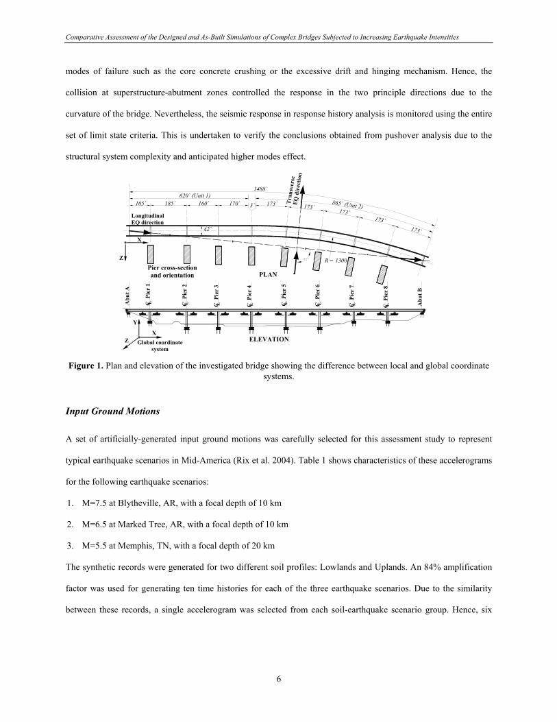
The plan and elevation of the investigated bridge are shown in Figure 1. Detailed description of the 1488 feet nine-
span curved bridge is provided elsewhere in Part I of this study (FHWA 1996). Two modeling approaches are
considered in the current study to investigate the significance of conventional design assumptions on capacity-
demand predictions of complex bridges. These are the ‘design assumption’ and the ‘as-built’ behavior. The latter
modeling realistically accounts for bridge bearings and their frictional resistance, structural gaps and material
response. The refined three-dimensional modeling approaches adopted to idealize the entire bridge and its
foundation for elastic and inelastic analysis were described and verified in Part I of this study and by Mwafy et al.
(2006). Inelastic response history analysis is carried out herein using the Mid-America Earthquake Center inelastic
analysis program Zeus-NL. The program has been extensively used in seismic design and assessment of buildings
and bridges and has been verified against full scale tests from Europe and the US. Further information about the
program and its comprehensive libraries and efficient nonlinear solution procedure is mentioned elsewhere
(Elnashai et al. 2004).
The adopted yield and collapse performance indicators were also discussed in Part I of the present study and by
Mwafy et al. (2006). Pushover analysis was employed to investigate and prioritize the selected set of limit state
criteria for response history analysis. The deformation restrictions at abutments prevented formation of undesirable
5
Comparative Assessment of the Designed and As-Built Simulations of Complex Bridges Subjected to Increasing Earthquake Intensities
modes of failure such as the core concrete crushing or the excessive drift and hinging mechanism. Hence, the
collision at superstructure-abutment zones controlled the response in the two principle directions due to the
curvature of the bridge. Nevertheless, the seismic response in response history analysis is monitored using the entire
set of limit state criteria. This is undertaken to verify the conclusions obtained from pushover analysis due to the
structural system complexity and anticipated higher modes effect.
105` 185` 160` 170` 173` 173`173`
173`173`
C P
ier
1L C P
ier
2L C P
ier
3L C P
ier
4L C
Pie
r 5
L C P
ier
6L C P
ier
7L C P
ier
8L A
but B
Abu
t A
PLAN
ELEVATION
620` (Unit 1)865` (Unit 2)3`
42`
R = 1300`
1488`
Longitudinal EQ direction
Tra
nsve
rse
EQ
dir
ectio
n
Z
X
Pier cross-section and orientation
Y
XZ Global coordinate
system Figure 1. Plan and elevation of the investigated bridge showing the difference between local and global coordinate
systems.
Input Ground Motions
A set of artificially-generated input ground motions was carefully selected for this assessment study to represent
typical earthquake scenarios in Mid-America (Rix et al. 2004). Table 1 shows characteristics of these accelerograms
for the following earthquake scenarios:
1. M=7.5 at Blytheville, AR, with a focal depth of 10 km
2. M=6.5 at Marked Tree, AR, with a focal depth of 10 km
3. M=5.5 at Memphis, TN, with a focal depth of 20 km
The synthetic records were generated for two different soil profiles: Lowlands and Uplands. An 84% amplification
factor was used for generating ten time histories for each of the three earthquake scenarios. Due to the similarity
between these records, a single accelerogram was selected from each soil-earthquake scenario group. Hence, six
6
Comparative Assessment of the Designed and As-Built Simulations of Complex Bridges Subjected to Increasing Earthquake Intensities
records were used in response history analysis. These are Lowland1, Lowland2, Lowland3, Upland1, Upland2 and
Upland3.
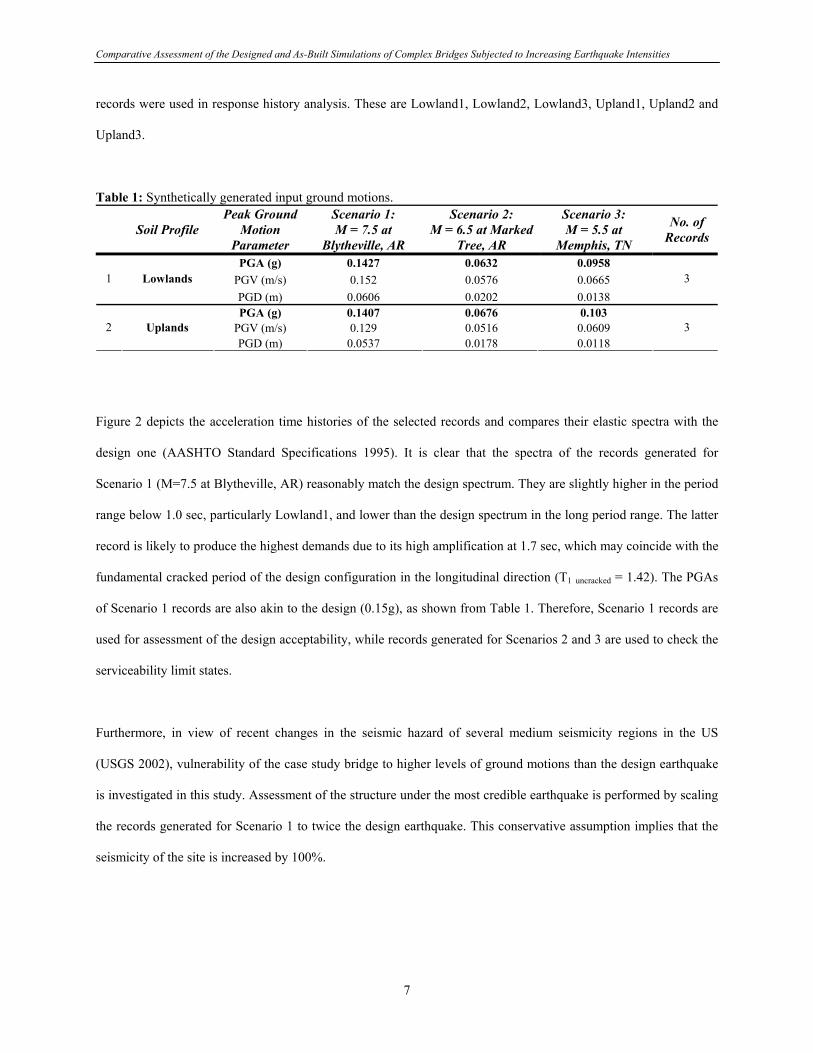
Table 1: Synthetically generated input ground motions.
Soil Profile Peak Ground
Motion Parameter
Scenario 1: M = 7.5 at
Blytheville, AR
Scenario 2: M = 6.5 at Marked
Tree, AR
Scenario 3: M = 5.5 at
Memphis, TN
No. of Records
PGA (g) 0.1427 0.0632 0.0958 PGV (m/s) 0.152 0.0576 0.0665 1 Lowlands PGD (m) 0.0606 0.0202 0.0138
3
PGA (g) 0.1407 0.0676 0.103 PGV (m/s) 0.129 0.0516 0.0609 2 Uplands PGD (m) 0.0537 0.0178 0.0118
3
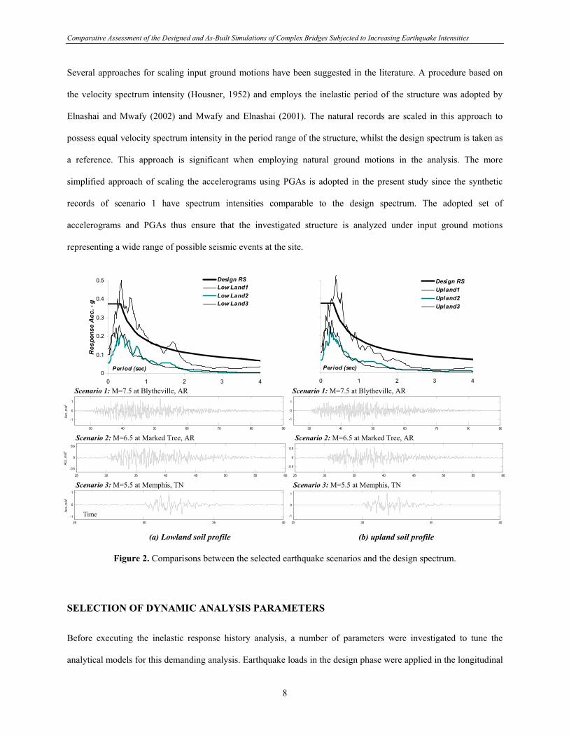
Figure 2 depicts the acceleration time histories of the selected records and compares their elastic spectra with the
design one (AASHTO Standard Specifications 1995). It is clear that the spectra of the records generated for
Scenario 1 (M=7.5 at Blytheville, AR) reasonably match the design spectrum. They are slightly higher in the period
range below 1.0 sec, particularly Lowland1, and lower than the design spectrum in the long period range. The latter
record is likely to produce the highest demands due to its high amplification at 1.7 sec, which may coincide with the
fundamental cracked period of the design configuration in the longitudinal direction (T1 uncracked = 1.42). The PGAs
of Scenario 1 records are also akin to the design (0.15g), as shown from Table 1. Therefore, Scenario 1 records are
used for assessment of the design acceptability, while records generated for Scenarios 2 and 3 are used to check the
serviceability limit states.
Furthermore, in view of recent changes in the seismic hazard of several medium seismicity regions in the US
(USGS 2002), vulnerability of the case study bridge to higher levels of ground motions than the design earthquake
is investigated in this study. Assessment of the structure under the most credible earthquake is performed by scaling
the records generated for Scenario 1 to twice the design earthquake. This conservative assumption implies that the
seismicity of the site is increased by 100%.
7
Comparative Assessment of the Designed and As-Built Simulations of Complex Bridges Subjected to Increasing Earthquake Intensities
Several approaches for scaling input ground motions have been suggested in the literature. A procedure based on
the velocity spectrum intensity (Housner, 1952) and employs the inelastic period of the structure was adopted by
Elnashai and Mwafy (2002) and Mwafy and Elnashai (2001). The natural records are scaled in this approach to
possess equal velocity spectrum intensity in the period range of the structure, whilst the design spectrum is taken as
a reference. This approach is significant when employing natural ground motions in the analysis. The more
simplified approach of scaling the accelerograms using PGAs is adopted in the present study since the synthetic
records of scenario 1 have spectrum intensities comparable to the design spectrum. The adopted set of
accelerograms and PGAs thus ensure that the investigated structure is analyzed under input ground motions
representing a wide range of possible seismic events at the site.
0
0.1
0.2
0.3
0.4
0.5
0 1 2 3
Period (sec)
Res
pons
e A
cc. -
g
4
Design RSLow Land1Low Land2Low Land3
0 1 2 3 4
Design RSUpland1Upland2Upland3
Period (sec)
Scenario 1: M=7.5 at Blytheville, AR
30 40 50 60 70 80 90
-1
0
1
Acc.
,m/s2
Scenario 2: M=6.5 at Marked Tree, AR
25 30 35 40 45 50 55 60
-0.5
0
0.5
Acc.
,m/s2
Scenario 3: M=5.5 at Memphis, TN
25 30 35 40
-1
0
1
Acc.
,m/s2
Scenario 1: M=7.5 at Blytheville, AR
30 40 50 60 70 80 90
-1
0
1
Scenario 2: M=6.5 at Marked Tree, AR
25 30 35 40 45 50 55 60
-0.5
0
0.5
Scenario 3: M=5.5 at Memphis, TN
25 30 35 40
-1
0
1
(a) Lowland soil profile
Time
(b) upland soil profile
Figure 2. Comparisons between the selected earthquake scenarios and the design spectrum.
SELECTION OF DYNAMIC ANALYSIS PARAMETERS
Before executing the inelastic response history analysis, a number of parameters were investigated to tune the
analytical models for this demanding analysis. Earthquake loads in the design phase were applied in the longitudinal
8

Comparative Assessment of the Designed and As-Built Simulations of Complex Bridges Subjected to Increasing Earthquake Intensities
direction along a straight line connecting the two base nodes at the end abutments. In the transverse direction, loads
were applied at a 90 degree to the longitudinal direction. As a result of the structure curvature, these directions are
inclined at 11° from the global X and Z axes, as shown from Figure 1. SAP2000 allows employing user-defined
local axes for loads, while the global coordinate system should be used in the inelastic analysis performed using
Zeus-NL. Response spectrum and elastic response history analyses were therefore undertaken to investigate the
significant of this inclination on the seismic demand predictions. Results obtained from applying the seismic loads
in both the local and global coordinate systems confirmed the insignificance of this minor inclination and the
applicability of using the global coordinate system in analysis. The analysis also emphasized the importance of
employing a refined time step in response history analysis performed using the selected set of synthetic
accelerograms. Thus, the analysis carried out using Zeus-NL employs the global coordinate system and a refined
time step (0.01 – 0.02 sec).
Damping is modeled in Zeus-NL using Rayleigh damping elements. The mass- and stiffness-proportional
parameters are calculated based on the predominant periods of the structure (Chopra 2000). Since the hysteretic
damping due to inelastic energy absorption is already accounted for in the inelastic analysis, two levels of Rayleigh
damping ratios are investigated; 1% and 2%. Table 2 shows comparison between results of elastic analysis with a
5% damping ratio and Zeus-NL inelastic response history analysis performed using different Rayleigh damping
levels (0, 1 and 2%). An elastic response is anticipated under the design earthquake due to the high overstrength
observed in the transverse direction (Mwafy et al. 2006). Therefore, it is anticipated to obtain comparable demands
from inelastic analysis compared with those from elastic analysis. It is observed that the 2% Rayleigh damping ratio
results in improved predictions of deformation and base shear demands, while those at the 1% damping are almost
twice the elastic analysis results. It was decided to maintain the Rayleigh damping in inelastic analysis at the 2%
level due to the high inelasticity expected in the longitudinal direction of the bridge (Mwafy et al. 2006).
The integration of equations of motion may be carried out in Zeus-NL by means of two different algorithms;
Newmark or Hilber-Hughes-Taylor integration algorithm (Broderick et al. 1994). The HHT algorithm requires an
additional parameter to control the level of numerical dissipation. Comparisons between results of the two schemes
confirmed the similarity between their results at the design earthquake. As confirmed from the study of Broderick et
9

Comparative Assessment of the Designed and As-Built Simulations of Complex Bridges Subjected to Increasing Earthquake Intensities
al. (1994), the HHT algorithm is more beneficial under high input ground motions since it can reduce the very high
short-duration peaks in the solution. Therefore, to increase both the accuracy and the numerical stability of the
analysis, the HHT scheme is employed in subsequent response history analysis.
Table 2. Comparison between elastic and inelastic demands at different damping levels (transverse direction). ZeusNL Inelastic Response History Analysis Elastic Analysis
(5% Damping) 0.0% Rayleigh Damping 1% Rayleigh Damping 2% Rayleigh Damping Support Disp. (mm) Shear (kN) Disp. (mm) Shear (kN) Disp. (mm) Shear (kN) Disp. (mm) Shear (kN)
Abutment A 10 32 17 14 Pier No.1 17 1721 33 5601 17 4363 14 3874 Pier No.2 33 2260 70 4404 61 4119 54 3898 Pier No.3 42 2811 104 6430 74 4800 65 4572 Pier No.4 50 3350 147 7645 103 6375 75 5061 Pier No.5 45 3123 94 5742 71 4687 59 4168 Pier No.6 35 2415 87 5475 73 4507 64 4317 Pier No.7 24 2411 50 5144 34 3762 34 3322 Pier No.8 20 2015 64 4989 49 3303 41 3794 Abutment B 11 70 60 48 Demands are at the pier base (shear) and at the pier top (displacements).
DEMAND PREDICTIONS AT THE DESIGN EARTHQUAKE
Response in Transverse Direction
Table 3 shows comparisons between the displacement and base shear demands of the design and the as-built
configurations obtained from inelastic response history analysis using the selected set of ground motions. Figure 3
depicts a sample comparison between the maximum displacement time-histories at top of piers and abutments of the
two modeling approaches investigated in this study.
The highest demands are generated from Lowland1 at Pier 4. The maximum displacement demands are higher by
50% than those obtained from response spectrum analysis using the design spectrum. This was expected since
Lowland1 is higher than the design spectrum in the period range below 1.0 sec, as shown from Figure 2. It is
noteworthy that the maximum total base shear demands shown in Table 3 are from summation of the response time-
histories not from summation of the peak values.
10

Comparative Assessment of the Designed and As-Built Simulations of Complex Bridges Subjected to Increasing Earthquake Intensities
The predominant cracked period in the transverse direction is 0.88 and 0.85 second for the design and the as-built
models, respectively. These are estimated from Fourier analysis of the top acceleration response of Pier 4, as shown
from Figure 4. The period of the structure in this direction is marginally influenced by the bearing friction, which is
expected to be more pronounced in the longitudinal direction. The maximum demands of the as-built bridge are
therefore akin to those of the design configuration. Nevertheless, comparison of the displacement time histories
shown in Figure 3 confirms the significant change in response of the curved unit of the bridge (Piers 5-8 and
Abutment B). Clearly, the significance of the bearing friction increases with the inclination of the local coordinate
system. Hence, it is more pronounced on Abutment B compared with Pier 5, while it has no effect on the straight
unit (Abutment A and Piers 1-3).
Table 3. Inelastic demands of the design and the as-built configurations in the transverse direction (kN - mm). Design Lowland1 Lowland2 Lowland3 Upland1 Upland2 Upland3 Location
Disp. Shear Disp. Shear Disp. Shear Disp. Shear Disp. Shear Disp. Shear Disp. ShearAbutment A 10 14 7 8 19 9 9 Top of Pier 1 17 1721 14 3874 7 1820 5 1300 19 4105 5 1387 5 1314 Top of Pier 2 33 2260 54 3898 21 2469 13 1605 50 3997 16 2006 12 1462 Top of Pier 3 42 2811 65 4572 28 2863 17 2145 44 3462 17 2172 16 1957 Top of Pier 4 50 3350 75 5061 48 4275 26 2740 75 4947 31 3300 20 2541 Top of Pier 5 45 3123 59 4168 39 3412 18 2297 48 3848 21 2717 17 2043 Top of Pier 6 35 2415 64 4317 26 3044 15 1701 42 3544 20 2169 14 1533 Top of Pier 7 24 2411 34 3322 10 3893 6 1332 23 3858 11 1742 6 1299 Top of Pier 8 20 2015 41 3794 11 1887 9 1263 23 3115 12 2017 8 1251 Abutment A 11 48 15 14 24 19 13
Des
ign
Total shear / Max disp. 50 20106 75 25556 48 17532 26 11294 75 19412 31 13340 20
10234
Abutment A 15 6 9 21 5 9 Top of Pier 1 19 4242 6 1729 5 1216 24 4337 5 1254 4 1153 Top of Pier 2 53 3939 19 4084 12 2557 52 6341 11 2376 11 2190 Top of Pier 3 59 4283 26 3607 17 2215 47 3601 15 1920 14 1838 Top of Pier 4 78 5309 48 3702 26 3387 75 5198 22 3063 18 2395 Top of Pier 5 54 4134 33 3702 17 2089 42 3885 16 2052 15 1824 Top of Pier 6 53 4213 20 2329 12 1470 45 3625 12 1449 10 1267 Top of Pier 7 19 3896 10 1989 5 1222 25 4075 6 1292 5 1091 Top of Pier 8 24 4062 9 2314 6 1264 21 3478 6 1556 5 1198 Abutment A 29 13 10 24 11 9
As-
built
Total shear / Max disp. 78 22140 48 16570 26 11239 75 22394 22 10824 18
9673Demands are at the pier base (shear) and at the pier top (displacements).
11
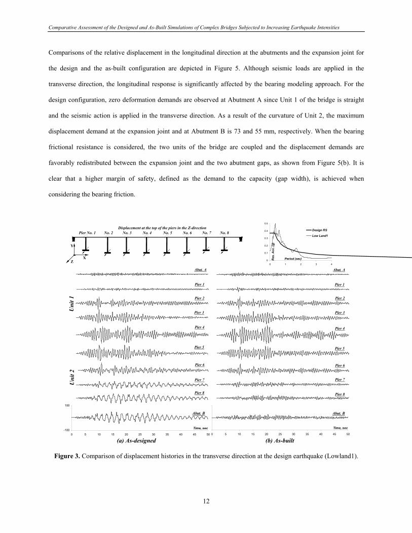
Comparative Assessment of the Designed and As-Built Simulations of Complex Bridges Subjected to Increasing Earthquake Intensities
Comparisons of the relative displacement in the longitudinal direction at the abutments and the expansion joint for
the design and the as-built configuration are depicted in Figure 5. Although seismic loads are applied in the
transverse direction, the longitudinal response is significantly affected by the bearing modeling approach. For the
design configuration, zero deformation demands are observed at Abutment A since Unit 1 of the bridge is straight
and the seismic action is applied in the transverse direction. As a result of the curvature of Unit 2, the maximum
displacement demand at the expansion joint and at Abutment B is 73 and 55 mm, respectively. When the bearing
frictional resistance is considered, the two units of the bridge are coupled and the displacement demands are
favorably redistributed between the expansion joint and the two abutment gaps, as shown from Figure 5(b). It is
clear that a higher margin of safety, defined as the demand to the capacity (gap width), is achieved when
considering the bearing friction.
Pier No. 1 No. 2 No. 3 No. 4 No. 5 No. 6 No. 7 No. 8
Z
Y
X
Displacement at the top of the piers in the Z-direction
0
0.1
0.2
0.3
0.4
0.5
0 1 2 3 4
Period (sec)Res
. Acc
. (g)
Design RS
Low Land1
Abut. A
Pier 1
Pier 2
Pier 3
Pier 4
Pier 5
Pier 6
Pier 7
Pier 8
Abut. A
Pier 1
Pier 2
Pier 3
Pier 4
Pier 5
Pier 6
Pier 7
Pier 8
-100
100
0 5 10 15 20 25 30 35 40 45 50
Time, sec
Abut. B
Uni
t 1
Uni
t 2
0 5 10 15 20 25 30 35 40 45 50
Time, sec
Abut. B
(a) As-designed (b) As-built
Figure 3. Comparison of displacement histories in the transverse direction at the design earthquake (Lowland1).
12

Comparative Assessment of the Designed and As-Built Simulations of Complex Bridges Subjected to Increasing Earthquake Intensities
0
0.2
0.4
0.6
0.8
1
0 0.5 1 1.5 2 0 0.5 1 1.5
Period (sec)
T = 0.85 sec
As-builtFour
ier A
mp.
T = 0.88 sec
As-designed
2
Figure 4. Fourier spectra of the acceleration response at top of Pier 4 (Lowland1).
-100
0
100
Rel
. Dis
p., m
m Abut. AGap width = 101.6 mm
Zero
-300-200-100
0100200300
Time, secRel
. Dis
p., m
m Exp. JointGap width = 304.8 mm
73
49 mm
-100
0
100
0 5 10 15 20 25 30 35 40 45 50
Rel
. Dis
p., m
m Abut. BGap width = 101.6 mm
55
44 mm
Time, sec
Abut. AGap width = 101.6 mm
11 mm
11 mm
Time, sec
Exp. JointGap width = 304.8 mm
31 mm
5 mm
0 5 10 15 20 25 30 35 40 45 50
Time, sec
Abut. BGap width = 101.6 mm
23 mm
11 mm
(a) As-designed (b) As-built
Figure 5. Comparison of relative displacement response in the longitudinal direction at the abutments and the expansion joint (load in transverse direction at the design EQ).
The elongation in period at the design earthquake is about 10% for the two analytical models investigated. This
reflects a minor concrete cracking and a response within the elastic range. No yielding is observed under the effect
of the six records employed here, confirming the high margin of safety. A comparison between the capacity and
maximum base shear demand of the design assumption and the as-built bridge at the design and twice the design
earthquake is shown in Figure 6. The capacities are estimated from inelastic pushover analysis of the entire bridge
(Mwafy et al. 2006), while the demands are conservatively estimated from Lowland1, which produces the highest
response. It is clear that maximum global demand under the design earthquake is well below the minimum supply
and the response of both the design and the as-built configuration is within the elastic range.
13
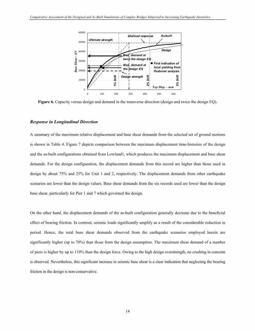
Comparative Assessment of the Designed and As-Built Simulations of Complex Bridges Subjected to Increasing Earthquake Intensities
0
10000
20000
30000
40000
50000
60000
0 100 200 300 400 500 600
Top Disp. - mm
Base
She
ar -
kN
1% D
rift
2% D
rift
3% D
rift
Design
As-builtUltimate strength
Idialized response
First indication of local yielding from Pushover analysis
Design strength
Max. demand at the design EQ
Max. demand at twice the design EQ
Figure 6. Capacity versus design and demand in the transverse direction (design and twice the design EQ).
Response in Longitudinal Direction
A summary of the maximum relative displacement and base shear demands from the selected set of ground motions
is shown in Table 4. Figure 7 depicts comparison between the maximum displacement time-histories of the design
and the as-built configurations obtained from Lowland1, which produces the maximum displacement and base shear
demands. For the design configuration, the displacement demands from this record are higher than those used in
design by about 75% and 25% for Unit 1 and 2, respectively. The displacement demands from other earthquake
scenarios are lower than the design values. Base shear demands from the six records used are lower than the design
base shear, particularly for Pier 1 and 7 which governed the design.
On the other hand, the displacement demands of the as-built configuration generally decrease due to the beneficial
effect of bearing friction. In contrast, seismic loads significantly amplify as a result of the considerable reduction in
period. Hence, the total base shear demands observed from the earthquake scenarios employed herein are
significantly higher (up to 70%) than those from the design assumption. The maximum shear demand of a number
of piers is higher by up to 110% than the design force. Owing to the high design overstrength, no crushing in concrete
is observed. Nevertheless, this significant increase in seismic base shear is a clear indication that neglecting the bearing
friction in the design is non-conservative.
14

Comparative Assessment of the Designed and As-Built Simulations of Complex Bridges Subjected to Increasing Earthquake Intensities
Table 4. Inelastic demands of the design and the as-built configurations in the longitudinal direction (kN - mm). Design Lowland1 Lowland2 Lowland3 Upland1 Upland2 Upland3 Location
Disp. Shear Disp. Shear Disp. Shear Disp. Shear Disp. Shear Disp. Shear Disp. Shear Abutment A 61.6 108 34 22 81 33 19 Top of Pier 1 61.5 3185 102 2389 28 1541 20 1290 75 1984 30 1448 15 1042 Top of Pier 2 62.1 1472 102 1291 35 834 25 709 81 1074 32 849 22 571 Top of Pier 3 62.4 1472 103 1249 33 872 23 658 79 1267 31 956 20 503 Top of Pier 4 a 1130 55 1330 23 805 21 717 50 1305 27 904 19 664 Top of Pier 5 80.9 1148 99 1345 49 745 26 718 57 1221 45 914 20 646 Top of Pier 6 78.2 1837 90 1537 45 928 23 648 55 369 43 940 19 499 Top of Pier 7 73.5 4057 84 2257 43 1593 17 1087 52 1700 35 1530 13 962 Top of Pier 8 68.7 1383 83 1501 44 1304 21 1301 56 1671 39 853 16 1321 Abutment A 80.6 80 43 19 51 37 16
Des
ign
Total shear / Max disp. 81.7 15684 108 6197 49 4817 26 3614 81 5070 45 5637 22 3518
Abutment A 67 26 19 49 18 12 Top of Pier 1 64 2191 26 1714 15 1425 45 1759 15 1089 9 779 Top of Pier 2 63 1849 21 1879 21 1116 52 2218 21 974 15 924 Top of Pier 3 67 1302 24 1250 18 773 50 1299 19 557 11 1044 Top of Pier 4 62 2394 31 1548 26 2214 55 2769 44 2393 21 2309 Top of Pier 5 58 2273 18 1676 19 2143 45 1971 23 2410 16 1824 Top of Pier 6 55 1216 16 773 18 779 43 1158 23 1061 14 822 Top of Pier 7 47 1638 16 1549 17 1256 40 1864 25 1960 13 1118 Top of Pier 8 44 2853 25 2837 16 2292 41 2629 29 4235 13 3884 Abutment A 40 20 19 38 21 17
As-
built
Total shear / Max disp. 67 10289 31 6261 26 4578 55 8474 44 5864 21 4051
Demands are at the pier base (shear) and at the pier top (displacement). a = 62.6 for Unit 1 and 81.7 for Unit 2 (design displacement demands were monitored in the superstructure).
Figure 7 confirms that the seismic response in this direction is fundamentally different for the two configurations
investigated. For the design assumption, the two units of the bridge have different dynamic characteristics and
seismic response. Hence, the displacement time-histories of Unit 1 (Abutment A and Piers 1-3) are different than
those of Unit 2 (Pier 5-8 and Abutment B), as shown in Figure 7(a). Pier 4 at the expansion joint has also its distinct
response. For the as-built model, the bearing friction couples the two units of the bridge and stimulates the
beneficial contribution of Piers 4, 5 and 8 to the lateral force resisting system. It is clear from Figure 7(b) that the
displacement response of Unit 1 is comparable to that of Unit 2, with different amplitudes.
Figure 8 depicts a comparison between Fourier spectra of the two configurations investigated obtained from the top
acceleration history at Pier 1. Clearly, the inelastic periods of the design assumption are significantly longer than the
15
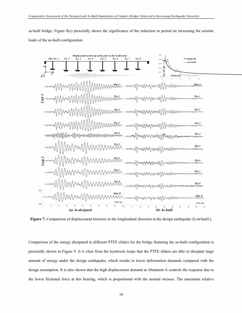
Comparative Assessment of the Designed and As-Built Simulations of Complex Bridges Subjected to Increasing Earthquake Intensities
as-built bridge. Figure 8(c) pictorially shows the significance of the reduction in period on increasing the seismic
loads of the as-built configuration.
Pier No. 1 No. 2 No. 3 No. 4 No. 5 No. 6 No. 7 No. 8
Z
Y
X
Displacement at the top of the piers in the X-direction
0
0.1
0.2
0.3
0.4
0.5
0 1 2 3 4
Period (sec)Res
. Acc
. (g)
Design RS
Low Land1
Abut. A
Pier 1
Pier 2
Pier 3
Pier 4
Pier 5
Pier 6
Pier 7
Pier 8
-100
100
0 5 10 15 20 25 30 35 40 45 50
Time, sec
Abut. B
Abut. A
Pier 1
Pier 2
Pier 3
Pier 4
Pier 5
Pier 6
Pier 7
Pier 8
0 5 10 15 20 25 30 35 40 45 50
Time, sec
Abut. B
Uni
t 1
Uni
t 2
(a) As-designed (b) As-built
Figure 7. Comparison of displacement histories in the longitudinal direction at the design earthquake (Lowland1).
Comparison of the energy dissipated in different PTFE sliders for the bridge featuring the as-built configuration is
pictorially shown in Figure 9. It is clear from the hysteresis loops that the PTFE sliders are able to dissipate large
amount of energy under the design earthquake, which results in lower deformation demands compared with the
design assumption. It is also shown that the high displacement demand at Abutment A controls the response due to
the lower frictional force at this bearing, which is proportional with the normal stresses. The maximum relative
16

Comparative Assessment of the Designed and As-Built Simulations of Complex Bridges Subjected to Increasing Earthquake Intensities
displacement demands at abutments are shown in Figure 7. The demand at Abutment A almost reaches the supply
(101.6 mm) for the design configuration. Also, high demands are observed at Abutment B and at the expansion
joint. The PTFE bearing frictional resistance significantly reduces these demands in the as-built bridge, particularly
at the expansion joint since the two units of the bridge oscillate simultaneously.
0
0.5
1
1.5
0 0.5 1 1.5 2
Period (sec)
Four
ier A
mp.
T = 1.51 sec
(a) As-designed
T = 1.6
0 0.5 1 1.5 2
T = 1.05 sec
T = 1.0 sec
(b) As-built
Four
ier A
mp.
0
0.1
0.2
0.3
0.4
0.5
0 1 2 3 4Period (sec)
Res
. Acc
. - g
Design RSLow Land1Low Land2Low Land3
As-designed
As-built
(c) Response spectra of input ground
Figure 8. Amplification of seismic forces due to the reduction in period in the longitudinal direction: (a) & (b)
Fourier spectra of the response at top Pier 2 for the design and the as-built configurations; (c) response spectra of the input ground motions.
-800
-600
-400
-200
0
200
400
600
800
-100 -50 0 50 100
Disp (mm)
Forc
e (k
N)
-800
-600
-400
-200
0
200
400
600
800
-100 -50 0 50 100
Disp (mm)
Forc
e (k
N)
-800
-600
-400
-200
0
200
400
600
800
-100 -50 0 50 100
Disp (mm)
Forc
e (k
N)
-800
-600
-400
-200
0
200
400
600
800
-100 -50 0 50 100
Disp (mm)
Forc
e (k
N)
-800
-600
-400
-200
0
200
400
600
800
-100 -50 0 50 100
Disp (mm)
Forc
e (k
N)
-800
-600
-400
-200
0
200
400
600
800
-50 0 50 100
Disp (mm)
Forc
e (k
N)
-100
4`` = 101.6 mm
Abutment
Superstructure12`` = 304.8 mm
Unit 1 Unit 2
Exp. Joint
Figure 9. Energy dissipated in PTFE sliders for the bridge featuring the as-built configuration at the design EQ.
Comparisons between the capacity, the design and the base shear demand at the design earthquake for the as-built
and the design configuration are shown in Figure 10(a). It is noteworthy that the total design force estimated from
17

Comparative Assessment of the Designed and As-Built Simulations of Complex Bridges Subjected to Increasing Earthquake Intensities
response spectrum analysis is over-conservative since it represents summation of maximum shear forces of various
piers, which do not simultaneously occur during the analysis. The realistic summation of base shear time-histories
obtained from response history analysis produces significantly lower demands. For both analytical idealizations
investigated, the minimum supply is higher than the maximum demand, which is in turn lower than the design.
0
4000
8000
12000
16000
20000
0 100 200 300 400 500 600
Top Disp. - mm1% D
rift
2% D
rift
3% D
rift
Design strength
Design assumption
As-builtStrength at 3% drift (σ max )
75% (σ max )
Idialized
Max. demand on the as-built bridge
Max. demand on the design bridge
Bas
e Sh
ear -
kN
(a) Design EQ
0 100 200 300 400 500 600
Top Disp. - mm1% D
rift
2% D
rift
3% D
rift
Design strengthDesign assumption
capacity
As-built capacityUltimate strength
Max. demand on the as-built bridge
Max. demand on the as-designed bridge
Without gabsWith gabs
(b) Twice the design EQ
Figure 10. Capacity versus design and demand in the longitudinal direction (design and twice the design EQ).
It is clear from the comprehensive capacity-demand comparisons presented above that the performance of the
design assumption in the longitudinal direction is satisfied at the design earthquake for all limit states except for the
segment collision criterion. This confirms the conclusions from pushover analysis discussed in the first phase of this
study. Including the frictional resistance of PTFE bearings redistributes the displacement demands to the tolerable
limits. The performance of the as-built bridge in this direction is therefore satisfactory for all limit states.
Nevertheless, it is important to stress that the investigated bridge exhibit high overstrength since the design was
governed by flow and ice loads (Mwafy et al. 2006). Therefore, the amplification of seismic forces and base shear
demands of the as-built bridge clearly confirms the high uncertainties arising from the assumptions typically used in
design of complex bridges.
18

Comparative Assessment of the Designed and As-Built Simulations of Complex Bridges Subjected to Increasing Earthquake Intensities
DEMAND PREDICTIONS AT TWICE THE DESIGN EARTHQUAKE
The results shown at the design earthquake indicated that the maximum demands are generated under the effect of
the Blytheville earthquake scenario. The accelerograms generated for this scenario were therefore scaled up to twice
the design ground motion and employed to investigate the vulnerability of the bridge under the most credible
earthquake. Comparisons between the maximum inelastic demands of the design and the as-built configuration at
twice the design earthquake are shown in Table 5.
Response in the Transverse Direction
The bearing friction is more pronounced at this high level of ground motion. It results in a reduction in period and
hence higher seismic forces. The demands of the as-built behavior are therefore higher than the as-designed
structure. Maximum demands are observed at Pier 4. Displacement demands are 100% higher than those observed
at the design earthquake and 300% higher than those used in design. The maximum observed drift at twice the
design ground motion is 0.80%, which is quite satisfactory. The maximum relative displacement demands (gap
close) in the longitudinal direction at the expansion joint and abutments are shown in Table 5. It is clear that no
collision is detected and the margin of safety is satisfactory at this high level of ground motion.
Table 5. Comparison between maximum inelastic displacement and base shear demands of the design and the as-built configuration at twice the design ground motion (kN - mm).
Transverse Direction Longitudinal Direction As-Built
Design Assumption As-Built Design Assumption Without Gaps With Gaps Location
Disp. Gaps a Shear Disp. Gaps a Shear Disp. Gaps a Shear Disp. Gaps a Shear Disp. Gaps a Shear
Abutment A 24 0.0 29 17 234 191 183 183 181 102 Top of Pier 1 27 5007 32 5797 226 3895 176 3536 172 3525Top of Pier 2 79 8555 89 9182 226 3173 189 3272 171 3397Top of Pier 3 92 5875 105 6198 228 2024 188 2007 176 2172Top of Pier 4 130 76 7564 158 17 8750 127 187 1754 133 74 1653 140 57 1652Top of Pier 5 96 5926 97 5947 147 1538 139 1497 127 1529Top of Pier 6 90 5795 92 6463 140 1631 130 1516 122 1713Top of Pier 7 49 5506 44 6159 125 1876 121 2925 115 2906Top of Pier 8 52 5831 48 6982 126 1945 115 1963 115 1924Abutment B 58 53 42 26 116 116 108 108 105 88 Total shear /
Max disp. 130 33960 158 35539 234 11835 189 15683 181 16016a: Maximum relative displacement (gap close) in the longitudinal direction at the expansion joint and abutments.
19

Comparative Assessment of the Designed and As-Built Simulations of Complex Bridges Subjected to Increasing Earthquake Intensities
Figure 11 shows the maximum relative displacement demands at abutments and the distribution of plastic hinges of
the as-built bridge. A comparison between the global capacity with the maximum base shear demand at this level of
ground motion is shown in Figure 6. It is clear that limited inelasticity is generated and the demands are well below
the minimum supply. The results confirm the satisfactory performance and the adequate margin of safety in the
transverse direction at twice the design ground motion.
17 mm
26 mm
17 mm
Figure 11. Maximum relative displacement demands of the as-built bridge at the expansion joint and abutments with distribution of plastic hinges (load in transverse direction at twice the design EQ).
Response in the Longitudinal Direction
Comparison between the inelastic demands of the design and the as-built bridge is shown in Table 5. The analysis
was conducted for the as-built bridge with and without modeling the structural gaps at abutments and the expansion
joint to highlight their significance on the seismic response. The inelastic demands in this direction significantly
increase at twice the design earthquake. Although base shear demands exceed the design forces for the majority of
substructural elements, no crushing in the concrete core is observed due to the exhibited high overstrength (Mwafy
et al. 2006). The response of the design assumption is unacceptable as a result of the high displacement demands,
which is almost twice the gap width capacity at abutment A.
The acceptable performance of the as-built structure was shown at the design earthquake. It was confirmed that
bearing friction effectively coupled the two units of the bridge and significantly improved the seismic capacity in
this direction. It is clear from the response time-histories shown in Figure 12 that the two units of the as-built bridge
simultaneously vibrate at twice the design PGA, confirming the significant effect of bearing friction. Modeling the
20

Comparative Assessment of the Designed and As-Built Simulations of Complex Bridges Subjected to Increasing Earthquake Intensities
segment collision at the gaps reduces the displacement demands, while it slightly increases the base shear of few
piers, as shown from Table 5. Figure 13 compares between the relative displacement response with and without
modeling the gaps at the abutments and the expansion joint. The results confirm the significance of seismic gaps
modeling on the response of multi-span curved bridges.
0
0.2
0.4
0.6
0.8
1
0 1 2 3 4
Period (sec)
Res
. Acc
. (g)
Design RS
Lowland1 at twicethe design EQ
(a) Distribution of plastic hinges of the as-built bridge Abut. AAbut. A
Pier 3
Pier 4
Pier 5
-200
-100
0
100
200
0 5 10 15 20 25 30 35 40 45 50
Time, sec
Abut. B
Uni
t 1
Pier 3
Pier 4
Pier 5
Uni
t 2
0 5 10 15 20 25 30 35 40 45 50
Time, sec
Abut. B
(b) As-designed (c) As-built with gaps
Figure 12. Response in longitudinal direction at twice the design earthquake: (a) mapping of plastic hinges for the bridge featuring the as-built configuration; (b) & (c) comparison of displacement histories for the design and the as-
built bridge.
-200
-100
0
100
200
Time, secRel
. Dis
p., m
m Abut. AGap width = 101.6 mm
170 mm
183 mm
-300-200-100
0100200
300
Time, secRel
. Dis
p., m
m Exp. JointGap width = 304.8 mm
42 mm
73 mm
-200
-100
0
100
200
0 5 10 15 20 25 30 35 40 45 50
Time, secRel
. Dis
p., m
m Abut. BGap width = 101.6 mm
87 mm
108 mm
Time, sec
Gap width = 101.6 mmAbut. A
181 mm
101.6 mm
Time, sec
Exp. JointGap width = 304.8 mm
57 mm
62 mm
0 5 10 15 20 25 30 35 40 45 50
Time, sec
Abut. BGap width = 101.6 mm
105 mm
88 mm
(a) Without gaps (b) With gaps
Figure 13. Comparison of relative displacement response in the longitudinal direction at the expansion joint and abutments with and without modeling of gaps (load in longitudinal direction at twice the design EQ).
21

Comparative Assessment of the Designed and As-Built Simulations of Complex Bridges Subjected to Increasing Earthquake Intensities
Comparisons of the capacity to demand ratios of the pinned and PTFE bearings indicate the acceptable response up
to twice the design earthquake. For pinned bearings, the superstructure inertia forces are transferred to the
substructure through anchor bolts at the top of the piers. The tension and shear capacities of these bolts are 387 kN
and 238 kN, respectively. The maximum tension and shear demands on the bolt are 303 kN and 176.7 kN,
respectively, which are lower than the capacities. For the PTFE bearings, the maximum seismic demand is 4139
kN., which produces a shear strain of 1.8. This results in a total shear strain lower than the allowable limit
recommended by seismic codes and guidelines (e.g. NCHRP 12-49 2001). Also, the maximum displacement
demand at the PTFE bearings in the longitudinal direction is lower than the sole plate limits. Hence, no damage is
anticipated to the PTFE surface.
Comparison of the overall capacity and maximum base shear demand for the design and the as-built bridge is shown
in Figure 10(b). For both configurations, the global demand at twice the design ground motion is slightly below the
ultimate capacity. However, the margin of safety of the as-built bridge is lower than the design assumption.
Although, controlling the deformation by seismic gaps prevents formation of undesirable modes of failure, it
increases base shear demands. The performance of the as-built bridge in the longitudinal direction is therefore
satisfactory for all limit states with the exception of the collision at abutments. The results support the conclusions
of the first phase of this study and emphasize the significance of pushover analysis procedure in identifying
potential structural deficiencies and prioritizing limit state criteria of complex bridges (Mwafy et al. 2006).
CONCLUSIONS
The importance of simplifying design assumptions on the capacity-demand ratio predictions of multi-span curved
bridges was investigated in this study. Verification of modeling approaches, prioritizing limit state criteria and
comparisons of the dynamic characteristics and capacities of the as-designed and the as-built configurations were
addressed in the first phase of the study. The current report presented results of the extensive response history
analyses carried out to compare between the inelastic behavior of the two bridge configurations at different levels of
ground motion. The following conclusions are drawn based on work reported above:
22

Comparative Assessment of the Designed and As-Built Simulations of Complex Bridges Subjected to Increasing Earthquake Intensities
• In the transverse direction, seismic demands and cracked periods were slightly influenced by bearing friction.
This was more pronounced on the curved unit, particularly with increasing the inclination of substructural
element. The displacement demands at abutments and the expansion joint though were significantly affected by
friction due to the coupling between the two units of the bridge in the longitudinal direction. Maximum
displacement and shear demands were 50% higher than the design due to the spectrum amplification in the
period range of the bridge. The redistribution of demands when considering bearing friction results in higher
margins of safety. The response at the design earthquake was within the elastic range and maximum demands
were well below minimum capacities.
• In longitudinal direction, the seismic response of the design assumption was alarming due to the imminent
collision at abutments, while it was satisfactory for the as-built bridge due to the uniform distribution of
demands. Piers with PTFE sliders effectively enhanced the lateral force resisting system when the bearing
friction was considered. Seismic loads though increased due to the considerable reduction in period, which in
turn magnified base shear demands. Base shear demands of the as-built configuration were therefore
significantly higher (up to 110%) than the design assumption. The results clearly highlighted the high
uncertainties arising from the assumptions typically used in design of complex bridges.
• At twice the design earthquake, the safety margins of the as-built bridge in the transverse direction were
satisfactory and the structure was just at the onset of the post-elastic range. In the longitudinal direction, the
displacement demands increased significantly, while base shear demands exceeded the design forces for the
majority of substructural elements. It was confirmed that bearing friction maintained the coupling between the
two units of the bridge up to this high level of ground motion. Modeling of structural gaps was significant in
analysis. Abutment gaps controlled the displacement demands, which resulted in limited inelasticity at this high
level of ground motion. The performance of the as-built bridge in the longitudinal direction was therefore
satisfactory for all limit states except for the collision at abutments.
The significance of simplifying design assumptions on the inelastic seismic response of the multi-span complex
bridge was confirmed from extensive response history analysis. The results are indicative of other complex bridges.
Neglecting bearing friction leads to a possible stiffness reduction in the structural system, resulting in longer periods
of vibration. This in turn results in significant reduction in design loads and high uncertainties in the seismic
23

Comparative Assessment of the Designed and As-Built Simulations of Complex Bridges Subjected to Increasing Earthquake Intensities
demand predictions. Assumptions aimed at simplifying the design process may therefore compromise the safety of
bridges similar to that studied here. Structural gaps at the abutments controlled the response of the curved bridge in
the two principle directions. Attention should be therefore focused on characterizing the behavior of joints and their
effect of design actions and deformations. Inelastic response history analysis confirmed and verified the
applicability of pushover analysis in identifying structural deficiencies and providing insight into the limit state
criteria of multi-span complex bridges at the design and twice the design levels.
ACKNOWLEDGMENTS
This study was funded by the US Federal Highway Administration (FHWA) through the Mid-America Earthquake
Center (MAE), University of Illinois at Urbana-Champaign, USA. The Mae Center is an Engineering Research
Center funded by the National Science Foundation under cooperative agreement reference EEC 97-01785. The
authors are grateful to Professor Glenn Rix, Georgia Institute of Technology, for his advice on earthquake input
motions.
24

Comparative Assessment of the Designed and As-Built Simulations of Complex Bridges Subjected to Increasing Earthquake Intensities
REFERENCES
1. AASHTO LRFD Specifications (2005). AASHTO LRFD bridge design specifications, 3rd Ed., American
Association of State Highway and Transportation Officials, Washington, D.C.
2. AASHTO Standard Specifications (1995). Standard specifications for highway bridges, 15th Ed., American
Association of State Highway and Transportation Officials, Washington, D.C.
3. Broderick, B.M., Elnashai, A.S., and Izzuddin, B.A. (1994). “Observations on the effect of numerical
dissipation on the nonlinear dynamic response of structural systems.” Engineering Structures, 16(1), 51-62.
4. Chopra, A.K. (2000). Dynamics of structures: Theory and applications to earthquake engineering, 2nd ed.,
Prentice Hall, Englewood Cliffs, New Jersey.
5. Elnashai, A.S., Papanikolaou, V., and Lee, D. (2004). Zeus-NL - a system for inelastic analysis of structures,
User Manual, Mid-America Earthquake Center, Civil and Environmental Engineering Department, Univ. of
Illinois at Urbana-Champaign, Urbana, IL.
6. Elnashai, A.S., and Mwafy, A.M. (2002). “Overstrength and force reduction factors of multistorey reinforced-
concrete buildings.” Struct. Design of Tall Buildings, 11(5), 329–351.
7. Housner G. (1952). Spectrum intensities of strong-motion earthquakes. Symp. on Earthquake and Blast Effects
on Structures. Los Angeles, Calif. 20-36.
8. Rix, G.J., Fernandez, A., and Foutch, D.A. (2004). “Synthetic earthquake hazard.” Project HD-1, Mid-
America Earthquake Center, <http://mae.cee.uiuc.edu> (Jan. 31, 06).
9. FHWA (1996). Seismic design of bridges – Design example No. 5 – Nine-span viaduct steel girder bridge, US
Department of Transportation, Publication No. FHWA-SA-97-010.
10. Mwafy, A.M., Elnashai, A.S., and Yen, W-H. (2006). “Implications of design assumptions on capacity
estimates and demand predictions of multi-span curved bridges”, ASCE Journal of Bridge Engineering, In
Press.
11. Mwafy, A.M., and Elnashai, A.S. (2001). “Static pushover versus dynamic collapse analysis of RC buildings.”
Eng. Structures, 23(5), 407-424.
12. USGS (2002). “Seismic hazard maps for the conterminous U.S. for 2002.” U.S. Geological Survey Earthquake
Hazards Program, <http://earthquake.usgs.gov> (Jan. 31, 06).
25