Assessment of ageing London Underground tunnels · Assessment of ageing London Underground...
40
Assessment of ageing London Underground tunnels: - Applying new technologies to old problems Tim Morrison and Peter Wright Tube Lines
Transcript of Assessment of ageing London Underground tunnels · Assessment of ageing London Underground...

Assessment of ageing London Underground tunnels:- Applying new technologies to old problems
Tim Morrison and Peter WrightTube Lines

Contents
• Background and purpose• Scope and programme• Methodology• Generic studies• Case study
- Analysis- Site measurements
• Summary & conclusions

Background and purpose
• PPP contract requirements- Status of assets before contract
• Asset knowledge and condition• Maintenance requirements
- Running an efficient service
• Long term investment needs- Second review period
Scope• Deep Tube Tunnel assets on the Jubilee,
Northern and Piccadilly lines• Approximately 187km of asset
- Running/platform tunnels, station passageways and shafts
• Approximately 1700 assets in total
Programme• Commenced in January 2003• Contractual deadline is end of December 2008• 18 months prior to end of first review period• Last 18 months to agree management process for
Deep Tube Tunnels in second review period

Methodology (1 of 2)• Detailed review of contract requirements• What existing data did we have?• Identify knowledge gaps• What information is required?• Infrastructure to hold data
- Asset database- Geographical Information System (GIS)
• Staged approach (next slide)• Identify problem areas early in programme

STAGED APPROACHMethodology (2 of 2)
Year 1 – Detailed desk study and initial assessments
Year 2 – Detailed assessment (10%) and 12 generic studies
Year 3 – Detailed assessment (20%) and 4 generic studies
Year 4 – Detailed assessment (70%)
Year 5 – Special access arrangements and completion of assessment programme
LESSONSLEARNT
LESSONSLEARNT
LESSONSLEARNT
LESSONSLEARNT

Generic studies
• Investigate on a global basis, rather than asset specific, wherever possible
• Apply results of these studies• Examples:
- Lining circularity- Cast iron lining thickness & strength- Geotechnical parameters

Tunnel case study• Twin cast iron running tunnels 11ft
8.25in dia, built 1907• 50m deep, 1.5m apart in London
clay• Location: Golders Green -
Hampstead• Assumed London clay
characteristics• Su = 50 + 8z kPa where z = depth• Eundrained = 400.Su (for geotech FE)• Eeff long term= 200.Su (for el. cont and struct FE)

Tunnel case study
• Analysis by- Elastic continuum- Geotechnical FE- 3D structural FE
• Site Measurements- Methods used- Interpretation
• Synthesis• Discussion and
tentative conclusions

Elastic continuum analysis• Actually it’s a single tunnel• K0 = σh’/ σv’ = 0.7 (to give a conservative
result)• Perfect build, no surcharge (not assessment)• Using Curtis/Muir Wood full-bond
(conservative)• Stiff Ring• Flexibility adjustment according to Muir Wood
– Ieff = Ij + I. (4/n)2 for n>4 (Ij = 0)

Elastic continuum results
• Stiff (monolithic)• Def 6.2mm; 12.4mm squat• CI Stress -101 to +12 MPa• N = 95%OB, M = 12kNm
• 6 segment flexible• Def 6.5mm; 13mm squat• CI Stress -75 to -15 MPa• N = 95%OB, M = 5.5kNm

Geotechnical FE• Using Crisp• CI Linings modelled as stiff ring
E =100 Gpa• 50% OB earth support / lining
preload. • Lining assumed permeable long
term• London clay soil model
• Mohr-Coulomb, non-associated dilation of 12.5%
• c’ = 15 kPa, Φ’ = 25 deg, • k = 1E-10 m/s• K0 = 1.0 initially
50%OB
50%OB
Excavation
Lining Erection

K0 Values
0
10
20
30
40
50
60
0 0.5 1 1.5 2 2.5 3
Ko'
Dep
th b
elow
top
of L
ondo
n C
lay
Jakis eqnKo' (unload)Ko' (reload)Ko' (50% underdrain)Ko' (Chudleigh)Ko (underdrained)

Geotechnical FE
Long term deformed mesh
LH tunnel constructedfirst
•Initial, long term squat = -1mm, 6mm•Ground loss at
excavation = 1.93% first tunnel, 1.69% second tunnel

Geotech FEHoop loadMax H=1638kN/m,Equivalent overburden=84% for 1st tunnel=50% for 2nd tunnel
Moment Max M=13.5kNm/mOr approx 7kNm/ring

Geotechnical FE
Surface Settlement
-80.0
-60.0
-40.0
-20.0
0.0-150 -100 -50 0 50 100 150
Offset (m)
Sett
lem
ent (
mm
)
Long term settlement – 36%
•Substantial long term settlement due to drainage of pore water into tunnel.
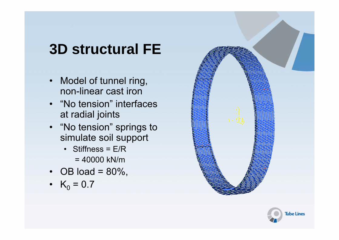
3D structural FE
• Model of tunnel ring, non-linear cast iron
• “No tension” interfaces at radial joints
• “No tension” springs to simulate soil support• Stiffness = E/R
= 40000 kN/m• OB load = 80%, • K0 = 0.7

Stresses alongtunnel axis rangefrom54MPa in tensionto41 MPa in compression
3D structural FE

Stresses around tunnel ring rangefrom89 MPa in tensionto97 MPa in compression
3D structural FE

3D structural FE
Looking at invert

Looking at invert,with LH segmentremoved
3D structural FE

3D structural FE results
• Lining behaviour is complex• Despite joints opening there is no tension at
bolt positions• Similar run on monolithic lining yields similar
results• “Effective” stresses difficult to assess, but
larger than expected from 2D analysis.• Lining squat = 25mm• Soil stiffness is main determining factor

Site measurements
• Lining thickness and loss of section• Strength of cast iron• London Clay strength and stiffness• Pore water pressures• Tunnel circularity• Tunnel stresses

Coring and ultrasonics in grey cast iron

Position of Coring & Ultasonic Inspection Results
NORTHBOUND RUNNING TUNNEL: Position of cores relative to each other (in all cases):
R1930 R1940 R3260
23.12 23.33 21.91 22.94 24.30 23.00
27.45 27.60 22.57 24.05 26.00 24.77
27.05 27.45 23.80 23.58 27.70 27.80
R3241 NORTHBOUND SOUTHBOUNDAverage measured thickness of core:
R1930 22.88 mm
19.10 20.20 R1940 20.10 mm
20.20 20.75 R3260 25.08 mm
21.77 24.60 R3241 20.38 mm
DIRECTION OF RUNNING
DIRECTION OF RUNNING
Typical coring and ultrasonic readings

Grey cast iron strength testing
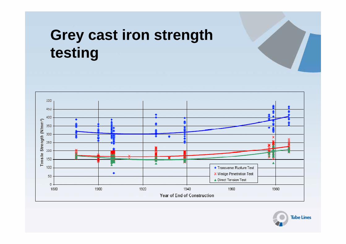
Grey cast iron strength testing
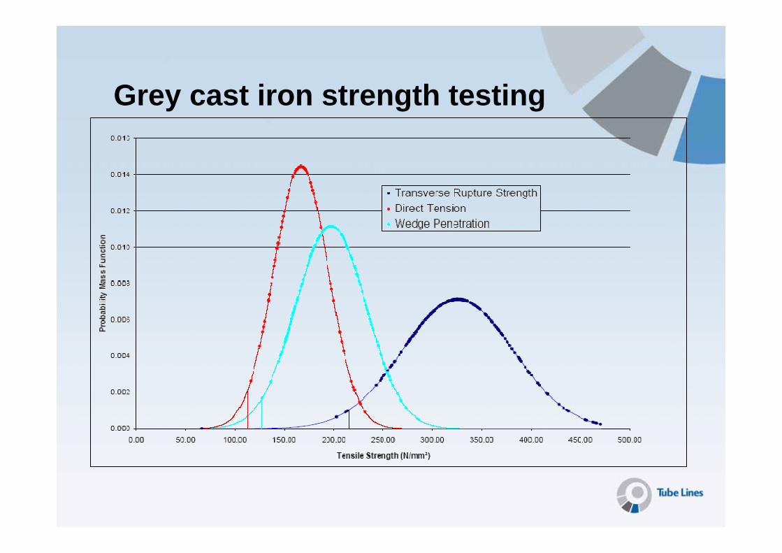
Grey cast iron strength testing

CPT and soil testing

CPT and soil testing

CPT and soil testing

CPT and soil testing
G=4.5+1.3z MPaequates to apprE=10.8+3.1z MPa
Assumed undrained E of 400.(50+8z)kPaequates to20+3.2z MPa

CPT and soil testing

Circularity measurement
Best-f it Perfect CircleCircularity Survey DataDeformation exaggerated x 10Estimated Centre
Typical circularity measurement, showing approx 1% squat
Circularity carried out using Leica3000 track trolley

-2.0
-1.0
0.0
1.0
2.0
860
900
940
980
1020
1060
1100
1140
1180
1220
1260
1300
1340
1380
1420
1460
1500
1540
1580
1620
1660
1700
1740
1780
1820
1860
1900
1940
1980
2020
2060
2100
2140
Northbound Ring Number
% o
oc (s
quat
+ve
)
-2.0
-1.0
0.0
1.0
2.0
1280
1320
1360
1400
1440
1480
1520
1560
1600
1640
1680
1720
1760
1800
1840
1880
1920
1960
2000
2040
2080
2120
2160
2200
2240
2280
2320
2360
2400
2440
2480
2520
2560
Southbound Ring Number
Circularity measurement
Typical longitudinal plot showing tunnel deformations between Golders Green and Hampstead

ACSM - StressProbe

ACSM - StressProbe
Stress across CI pan (N/mm2)
Hoop Load adjacent to Opening

Tentative Summary
4, axis-712, stiff5.5, flexible
Max moment/ring (kNm)
50-80Assumed 8084, first50, second
95, stiff and flexible
% Hoop load
35-659578101, stiff75, flexible
Max comp stress (kPa)
-89012, stiff-14 flexible
Max tens stress (kPa)
≈ 0.67% 2625, flexible
6.0 Stiff12.4, Stiff13, flexible
Diametric squat (mm)
Site3D FEGeo FEEl Cont

Summary and conclusions• Tunnel assessment work now nearly complete• Tube Lines Tunnels team have used a combination
of in house and external expertise to carry out• Analysis • Investigation• Inspection• Assessment• Reporting• Classification
• Further back-analysis work required to be done to understand the tunnels more completely
• Tim Morrison ([email protected])• Peter Wright ([email protected])
Acknowledgements
London UndergroundMetronetMott MacDonaldHalcrowSir Robert McAlpineOve Arup & PartnersLankelma CPT LimitedCastings Technology InternationalComech
Norwegian Geotechnical InstituteConstructive Evaluation LtdTSC Inspection SystemsManex UK LtdGeotechnical Consulting groupCorus