Assertion of contribution copyright...
28
Document technical content created by M J Maytum 2013 Copyright of M J Maytum For licence permissions contact [email protected] i Assertion of contribution copyright ownership 1 1. IEEE-SA Standards Board Bylaws 2 7.2.2 Contributions not previously published 3 For any contribution that has not been previously Published, and that is not Public Domain: 4 a) The IEEE has the non-exclusive, irrevocable, royalty-free, worldwide rights (i.e., a license) to use 5 the contribution in connection with the standards project for which the contribution was made. 6 b) Upon approval of the standard, the IEEE has the right to exploit and grant permission to use the 7 standard's content derived from the contribution in any format or media without restriction. 8 Copyright ownership of the original contribution is not transferred or assigned to the IEEE. 9 2. Contribution copyright ownership 10 Due to a recent misunderstanding on the difference between a personal contribution and an IEEE-SA Work 11 product, I am defining my copyrighted contribution (attached) to the following project: 12 PC62.69: Standard for the surge parameters of isolating transformers used in networking devices and 13 equipment 14 15 16 Michael John Maytum Date: 2013-08-31 17 30 Church Road 18 Willington 19 Bedford 20 Bedfordshire 21 MK44 3QB 22 UK 23 email: [email protected] 24
Transcript of Assertion of contribution copyright...
Document technical content created by M J Maytum
2013 Copyright of M J Maytum
For licence permissions contact [email protected]
i
Assertion of contribution copyright ownership 1
1. IEEE-SA Standards Board Bylaws 2
7.2.2 Contributions not previously published 3
For any contribution that has not been previously Published, and that is not Public Domain: 4
a) The IEEE has the non-exclusive, irrevocable, royalty-free, worldwide rights (i.e., a license) to use 5 the contribution in connection with the standards project for which the contribution was made. 6
b) Upon approval of the standard, the IEEE has the right to exploit and grant permission to use the 7 standard's content derived from the contribution in any format or media without restriction. 8
Copyright ownership of the original contribution is not transferred or assigned to the IEEE. 9
2. Contribution copyright ownership 10
Due to a recent misunderstanding on the difference between a personal contribution and an IEEE-SA Work 11 product, I am defining my copyrighted contribution (attached) to the following project: 12
PC62.69: Standard for the surge parameters of isolating transformers used in networking devices and 13 equipment 14
15
16
Michael John Maytum Date: 2013-08-31 17 30 Church Road 18 Willington 19 Bedford 20 Bedfordshire 21 MK44 3QB 22 UK 23
email: [email protected] 24
mickm
Pencil
Document technical content created by M J Maytum
2013 Copyright of M J Maytum
For licence permissions contact [email protected]
ii
Contribution made to 1
PC62.69: Standard for the surge 2
parameters of isolating transformers 3
used in networking devices and 4
equipment 5
Document technical content created by M J Maytum
2013 Copyright of M J Maytum
For licence permissions contact [email protected]
iii
Abstract: This standard sets terms, test methods, test circuits, measurement procedures and 1 preferred result values for the surge mitigation parameters of isolating transformers used in 2 networking devices and equipment. Three types of isolating transformer are considered; mains 3 low frequency power, high frequency power (switching mode power supplies) and signal (e.g. 4 Ethernet data). The surge parameters of the isolating transformer insulation covered by this 5 standard are: 6
⎯ Rated impulse voltage 7 ⎯ Input winding to output winding capacitance 8 ⎯ Insulation resistance 9
Additional parameters for signal isolating transformers are: 10 ⎯ Core saturation voltage-time product 11 ⎯ Rated input winding rms current for a given temperature rise 12
This standard does not cover the transformer parameters required to ensure appropriate 13 operation on the service e.g. signal transformer return loss. 14 15 Keywords: insulation, transformer, surge, breakdown, insulation resistance, impulse voltage, 16 1.2/50, lightning overvoltage 17 18
Document technical content created by M J Maytum
2013 Copyright of M J Maytum
For licence permissions contact [email protected]
iv
3. Introduction 1
Optical fiber to the home has been gradually replacing the wire feed telephone service since about 2005. 2 Fiber to the home deployment rapidly increased from 2010 onwards. Along with the increase of 3 installations there was a disproportionate increase in the failures of home networking equipment [B1], [B2] 4 and [B3]1 due to lightning overvoltages. Failures of the Ethernet Local Area Network (LAN) ports were 5 attributed to use of inappropriate Surge Protective Devices (SPDs) and lack of insulation coordination 6 which caused the insulation breakdown of mains low frequency power transformers, switching mode power 7 supply transformers, Ethernet signal transformers and in the associated wiring and connectors. This is a 8 global problem with home networking equipment failures being reported in Japan [B4] and the US [B5]. 9
1 The numbers in brackets correspond to those of the bibliography in Annex A.
Document technical content created by M J Maytum
2013 Copyright of M J Maytum
For licence permissions contact [email protected]
v
Contents 1
1. IEEE-SA Standards Board Bylaws.............................................................................................................. i 2
2. Contribution copyright ownership............................................................................................................... i 3 1.1 Scope ................................................................................................................................................... 1 4 1.2 Purpose ................................................................................................................................................ 1 5
2. Definitions, symbols, acronyms and abbreviations .................................................................................... 2 6 2.1 Definitions ........................................................................................................................................... 2 7 2.2 Symbols ............................................................................................................................................... 4 8 2.3 Acronyms and abbreviations ............................................................................................................... 5 9
3. Surge parameters ........................................................................................................................................ 5 10 3.1 Transformer surge mitigation .............................................................................................................. 5 11 3.2 Common-mode surges ......................................................................................................................... 7 12 3.3 Differential-mode surges ..................................................................................................................... 7 13
4. Characteristics ............................................................................................................................................ 7 14 4.1 Characteristic measurement................................................................................................................. 7 15 4.2 Inter-winding capacitance.................................................................................................................... 8 16 4.3 Insulation resistance (IR)................................................................................................................... 10 17 4.4 Signal transformer voltage-time product ........................................................................................... 12 18
5. Ratings...................................................................................................................................................... 13 19 5.1 Rating verification ............................................................................................................................. 13 20 5.2 Rated impulse voltage........................................................................................................................ 13 21 5.3 Signal transformer rated winding dc.................................................................................................. 17 22
Annex A (informative) Bibliography .......................................................................................................... 20 23
Annex B (informative) 1.2/50 Impulse......................................................................................................... 22 24 B.1 Introduction....................................................................................................................................... 22 25 B.2 Term definitions................................................................................................................................ 22 26 B.3 1.2/50 waveform parameters............................................................................................................. 23 27
28
29
30
Document technical content created by M J Maytum
2013 Copyright of M J Maytum
For licence permissions contact [email protected]
1
Contribution made to 1
Contribution made to 2
PC62.69: Standard for the surge 3
parameters of isolating transformers 4
used in networking devices and 5
equipment 6
7
8
1. Overview 9
1.1 Scope 10
see PAR 11
1.2 Purpose 12
see PAR 13
Document technical content created by M J Maytum
2013 Copyright of M J Maytum
For licence permissions contact [email protected]
2
2. Definitions, symbols, acronyms and abbreviations 1
2.1 Definitions 2
For the purposes of this document, the following terms and definitions apply. The IEEE Standards 3 Dictionary: Glossary of Terms and Definitions1 and the IEC Glossary2 should be consulted for terms not 4 defined in this clause. 3 5
breakdown: failure, at least temporarily, of the insulating properties of an insulating medium under 6 electric stress 7
NOTE—See Standard IEC 61340-1:2012, Ed. 1.0 [B19] 8
component type: manufacturer’s type of a component, e.g. its product name 9
clearance: shortest distance in air between two conductive parts 10
NOTE—See Standard IEC/TR 60664-2-1:2011, ed. 2.0 [B8] 11
creepage distance: shortest distance along the surface of a solid insulating material between two 12 conductive parts 13
NOTE—See Standard IEC/TR 60664-2-1:2011, ed. 2.0 [B8] 14
guarded measurement (three terminal network): measurement technique that allows the direct 15 impedance between two terminals to be measured correctly by applying a compensating voltage to the third 16 terminal that removes the shunting effects of any impedances to the third terminal. 17
hazard: potential source of harm 18
NOTE 1— The term hazard can be qualified in order to define its origin (e.g. electrical hazard, mechanical hazard) or 19 the nature of the potential harm (e.g. electric shock hazard, cutting hazard, toxic hazard, fire hazard). 20
NOTE 2— See IEC GUIDE 116, Ed. 1.0 (2010-08) [B18] 21
impulse withstand voltage: highest peak value of impulse voltage of prescribed form and polarity which 22 does not cause breakdown of insulation under specified conditions 23
NOTE—See Standard IEC/TR 60664-2-1:2011, ed. 2.0 [B8] 24
insulation (electrical): electrical separation between circuits or conductive parts provided by clearance or 25 creepage distance or solid insulation or combinations of them 26
NOTE—See Standard IEC 62477-1:2012, ed. 1.0 [B12] 27
insulation coordination: mutual correlation of insulation characteristics of electrical equipment taking into 28 account the expected micro-environment and other influencing stresses 29
NOTE—See Standard IEC/TR 60664-2-1:2011, ed. 2.0 [B8] 30
1IEEE Standards Dictionary: Glossary of Terms and Definitions is available at http://shop.ieee.org. 2 International Electrotechnical Commission Glossary is available at http://std.iec.ch/terms/terms.nsf/welcome?OpenForm 3 The reproduction of the IEC copyright terms and definitions from IEC Standards in Database Format are done under the license terms given at http://www.iec.ch/about/copyright/copyright-db_entry.htm
Document technical content created by M J Maytum
2013 Copyright of M J Maytum
For licence permissions contact [email protected]
3
insulation resistance: resistance under specified conditions between two conductive bodies separated by 1 the insulating material 2
NOTE—See Standard IEC 62631-1, ed. 1.0 (2011-04) [B9] 3 isolating transformer: transformer with protective separation between the input and output windings 4
NOTE—See Standard IEC 60065, ed. 7.0 (2001-12) [B10] 5
lightning overvoltage: transient overvoltage at any point of the system due to a specific lightning 6 discharge 7
NOTE—See Standard IEC 60664-1, ed. 2.0 (2007-04) [B7] 8
overvoltage: any voltage having a peak value exceeding the corresponding peak value of maximum 9 steady-state voltage at normal operating conditions 10
NOTE—See Standard IEC/TR 60664-2-1:2011, ed. 2.0 [B8] 11
rated impulse voltage: impulse withstand voltage value assigned by the manufacturer to the equipment or 12 to a part of it, characterizing the specified withstand capability of its insulation against transient 13 overvoltages 14
NOTE— See Standard IEC/TR 60664-2-1:2011, ed. 2.0 [B8] 15
rated winding dc: maximum winding current that will not cause the winding conductor temperature to 16 exceed a specified increase above the ambient temperature 17
electric screen: screen of conductive material intended to reduce the penetration of an electric field into a 18 given region 19
NOTE—See Standard IEC 60050-151:2011, ed. 2.0 [B11] 20
surge: temporary disturbance on the conductors of an electrical service caused by an electrical event not 21 related to the service. 22
thermal equilibrium: variation of less than 1 K between any two out of three consecutive measurements 23 made at an interval of 5 min 24
NOTE—See Standard IEC 61810-1 Ed3.0 [B20] 25
thermal resistance: quotient of the temperature difference between two specified points or regions and the 26 heat flow between these two points or regions under conditions of thermal equilibrium 27
NOTE 1— For most cases, the heat flow can be assumed to be equal to the power dissipation. 28
NOTE 2— See Standard IEC 62590, Ed. 1.0 [B21] 29
withstand voltage: voltage to be applied to a specimen under prescribed test conditions which does not 30 cause breakdown and/or flashover of a satisfactory specimen 31
NOTE—See Standard IEC/TR 60664-2-1:2011, ed. 2.0 [B8] 32
Document technical content created by M J Maytum
2013 Copyright of M J Maytum
For licence permissions contact [email protected]
4
2.2 Symbols 1
There are several standardized symbols that can used to represent a transformer in a graphic. This standard 2 uses the Form 2 type transformer symbol of IEC 60617 [B13], where the winding is represented by a series 3 of half circles. Figure 1 shows the symbol for a two winding transformer, similar to the S00842 symbol of 4 IEC 60617 [B13] made with terminal connections. 5
6
Figure 1 —Symbol for a two winding transformer 7 Figure 2 shows the symbol for a two winding transformer with instantaneous voltage polarity indicators, 8 similar to the S00843 symbol of IEC 60617 [B13] made with terminal connections. 9
10
Figure 2 —Symbol for a two winding transformer with polarity indication 11 Figure 3 shows the symbol for a two winding transformer with an electric screen between the windings, 12 similar to the S00853 symbol of IEC 60617 [B13] made with terminal connections. 13
14
Figure 3 —Symbol for a two winding transformer with electric screen 15 Figure 4 shows the symbol for a transformer center tapped windings, similar to the S00855 symbol of IEC 16 60617 [B13] made with two centre tapped windings and terminal connections. When testing is done with 17 shorted windings the center tap is also connected to the short, other testing is done without any connection 18 to the center tap terminal. 19
CT CT
20
Document technical content created by M J Maytum
2013 Copyright of M J Maytum
For licence permissions contact [email protected]
5
Key 1
CT Center tap terminal
Figure 4 —Transformer with center tapped windings 2
2.3 Acronyms and abbreviations 3
LAN Local Area Network
IR Insulation Resistance
ICT Information and Communications Technology
RMS Root-Mean Squared
3. Surge parameters 4
3.1 Transformer surge mitigation 5
An isolating transformer couples a service across the transformer insulation by magnetic induction. When 6 common-mode surges occur on the incoming service the insulation is voltage stressed. The insulation has 7 three physical paths: 8
⎯ transformer winding insulation: insulating material interposed between the two windings. 9 ⎯ creepage distance 10 ⎯ clearance 11
Clearance distances should be set so that the maximum expected voltage difference does not break down 12 the clearance. Creepage distances should be set so that the maximum expected voltage difference and 13 pollution degree do not cause surface flashover or breakdown (tracking). Solid insulation thickness should 14 be set so that the maximum expected voltage difference does not cause breakdown. 15
The higher frequency components of a surge impulse will be a.c. coupled by the transformer inter-winding 16 capacitance (shown as CP-SA + CP-SB) from one winding to the other, see Figure 5. 17
Document technical content created by M J Maytum
2013 Copyright of M J Maytum
For licence permissions contact [email protected]
6
WP WS
CP-SA
CP-SB
R
ZS ZT
1
Key 2
WP Primary winding CP-SA, CP-SB Primary to Secondary capacitance, paths A and B WS Secondary winding ZS Service source impedance ES Electric screen ZT Terminating or load impedance R Reference plane or point
Figure 5 —Common-mode surge conditions for the transformer 3 To reduce inter-winding capacitance a conducting electric screen can be used between the windings, see 4 Figure 6. The electric screen decouples most of the winding capacitance (shown as CP-ScreenA, CP-ScreenB, CS-5 ScreenA and CS-ScreenB) leaving a much smaller value of inter-winding capacitance (shown as CP-SA + CP-SB). 6
WP WS
ES
CP-SA
CP-ScreenA
CP-SB
CS-ScreenA
CP-ScreenB CS-ScreenB
R
ZS ZT
7
Key 8
WP Primary winding CP-ScreenA, CP-ScreenB Primary to Screen capacitance, paths A and B WS Secondary winding CS-ScreenA, CP-ScreenB Secondary to Screen capacitance, paths A and B ES Electric screen CP-SA, CP-SB Primary to Secondary unscreened capacitance,
paths A and B ZS Service source impedance ZT Terminating or load impedance R Reference plane or point
Figure 6 —Common-mode surge conditions for a transformer with an electric screen 9
Document technical content created by M J Maytum
2013 Copyright of M J Maytum
For licence permissions contact [email protected]
7
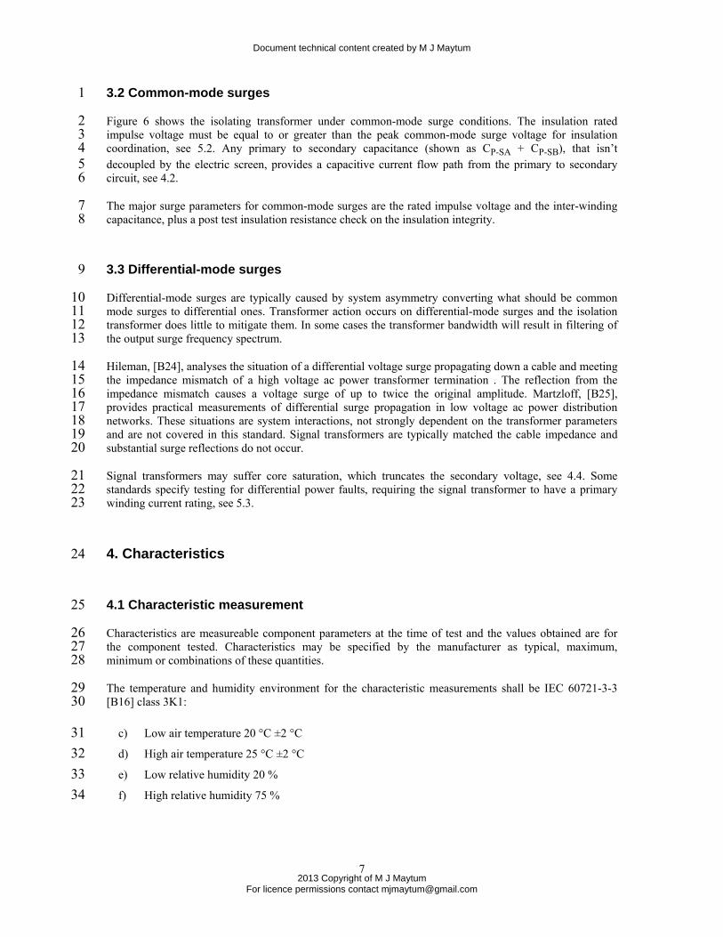
3.2 Common-mode surges 1
Figure 6 shows the isolating transformer under common-mode surge conditions. The insulation rated 2 impulse voltage must be equal to or greater than the peak common-mode surge voltage for insulation 3 coordination, see 5.2. Any primary to secondary capacitance (shown as CP-SA + CP-SB), that isn’t 4 decoupled by the electric screen, provides a capacitive current flow path from the primary to secondary 5 circuit, see 4.2. 6
The major surge parameters for common-mode surges are the rated impulse voltage and the inter-winding 7 capacitance, plus a post test insulation resistance check on the insulation integrity. 8
3.3 Differential-mode surges 9
Differential-mode surges are typically caused by system asymmetry converting what should be common 10 mode surges to differential ones. Transformer action occurs on differential-mode surges and the isolation 11 transformer does little to mitigate them. In some cases the transformer bandwidth will result in filtering of 12 the output surge frequency spectrum. 13
Hileman, [B24], analyses the situation of a differential voltage surge propagating down a cable and meeting 14 the impedance mismatch of a high voltage ac power transformer termination . The reflection from the 15 impedance mismatch causes a voltage surge of up to twice the original amplitude. Martzloff, [B25], 16 provides practical measurements of differential surge propagation in low voltage ac power distribution 17 networks. These situations are system interactions, not strongly dependent on the transformer parameters 18 and are not covered in this standard. Signal transformers are typically matched the cable impedance and 19 substantial surge reflections do not occur. 20
Signal transformers may suffer core saturation, which truncates the secondary voltage, see 4.4. Some 21 standards specify testing for differential power faults, requiring the signal transformer to have a primary 22 winding current rating, see 5.3. 23
4. Characteristics 24
4.1 Characteristic measurement 25
Characteristics are measureable component parameters at the time of test and the values obtained are for 26 the component tested. Characteristics may be specified by the manufacturer as typical, maximum, 27 minimum or combinations of these quantities. 28
The temperature and humidity environment for the characteristic measurements shall be IEC 60721-3-3 29 [B16] class 3K1: 30
c) Low air temperature 20 °C ±2 °C 31 d) High air temperature 25 °C ±2 °C 32 e) Low relative humidity 20 % 33 f) High relative humidity 75 % 34
Document technical content created by M J Maytum
2013 Copyright of M J Maytum
For licence permissions contact [email protected]
8
4.2 Inter-winding capacitance 1
4.2.1 Purpose 2
This test measures the effective inter-winding capacitance of the transformer 3
4.2.2 Test method 4
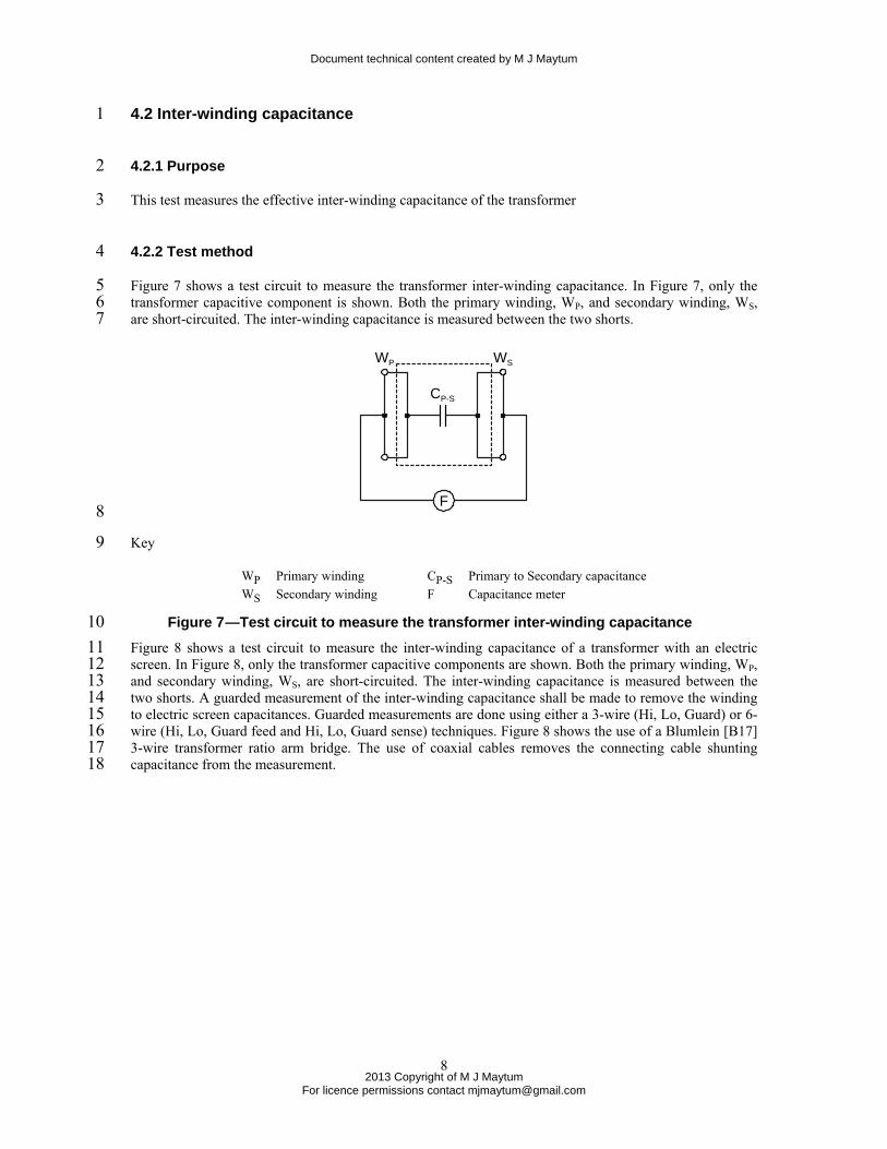
Figure 7 shows a test circuit to measure the transformer inter-winding capacitance. In Figure 7, only the 5 transformer capacitive component is shown. Both the primary winding, WP, and secondary winding, WS, 6 are short-circuited. The inter-winding capacitance is measured between the two shorts. 7
F
CP-S
WP WS
8
Key 9
WP Primary winding CP-S Primary to Secondary capacitance WS Secondary winding F Capacitance meter
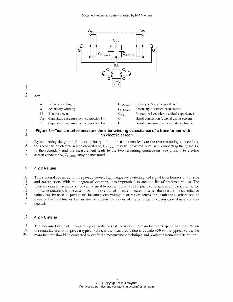
Figure 7 —Test circuit to measure the transformer inter-winding capacitance 10 Figure 8 shows a test circuit to measure the inter-winding capacitance of a transformer with an electric 11 screen. In Figure 8, only the transformer capacitive components are shown. Both the primary winding, WP, 12 and secondary winding, WS, are short-circuited. The inter-winding capacitance is measured between the 13 two shorts. A guarded measurement of the inter-winding capacitance shall be made to remove the winding 14 to electric screen capacitances. Guarded measurements are done using either a 3-wire (Hi, Lo, Guard) or 6-15 wire (Hi, Lo, Guard feed and Hi, Lo, Guard sense) techniques. Figure 8 shows the use of a Blumlein [B17] 16 3-wire transformer ratio arm bridge. The use of coaxial cables removes the connecting cable shunting 17 capacitance from the measurement. 18
Document technical content created by M J Maytum
2013 Copyright of M J Maytum
For licence permissions contact [email protected]
9
CP-S
WP WS
CP-Screen CS-Screen
F
ES
GG
GG
CH CL
1
Key 2
WP Primary winding CP-Screen Primary to Screen capacitance WS Secondary winding CS-Screen Secondary to Screen capacitance ES Electric screen CP-S Primary to Secondary residual capacitance CH Capacitance measurement connection Hi G Guard connection (coaxial cables screen) CL Capacitance measurement connection Lo F Guarded measurement capacitance bridge
Figure 8 —Test circuit to measure the inter-winding capacitance of a transformer with 3 an electric screen 4
By connecting the guard, G, to the primary and the measurement leads to the two remaining connections, 5 the secondary to electric screen capacitance, CS-Screen, may be measured. Similarly, connecting the guard, G, 6 to the secondary and the measurement leads to the two remaining connections, the primary to electric 7 screen capacitance, CP-Screen, may be measured. 8
4.2.3 Values 9
This standard covers ac low frequency power, high frequency switching and signal transformers of any size 10 and construction. With this degree of variation, it is impractical to create a list of preferred values. The 11 inter-winding capacitance value can be used to predict the level of capacitive surge current passed on to the 12 following circuitry. In the case of two or more transformers connected in series their insulation capacitance 13 values can be used to predict the instantaneous voltage distribution across the insulations. Where one or 14 more of the transformer has an electric screen the values of the winding to screen capacitance are also 15 needed. 16
4.2.4 Criteria 17
The measured value of inter-winding capacitance shall be within the manufacturer’s specified limits. When 18 the manufacturer only gives a typical value, if the measured value is outside ±30 % the typical value, the 19 manufacturer should be contacted to verify the measurement technique and product parameter distribution. 20

Document technical content created by M J Maytum
2013 Copyright of M J Maytum
For licence permissions contact [email protected]
10
4.3 Insulation resistance (IR) 1
4.3.1 Purpose 2
This test measures the resistance of the insulation at a defined dc voltage. 3
4.3.2 Test method 4
The insulation resistance meter shall be set for the specified value of dc test voltage, see 4.3.3. The test 5 voltage shall be applied for at least 60 s before the insulation resistance value is taken. 6
Figure 9 shows the test circuit to measure the insulation resistance of a transformer. Both the primary 7 winding, WP, and secondary winding, WS, are short-circuited. The insulation resistance is measured 8 between the two shorts. 9
WP WS
10 Key 11
WP Primary winding Ω IR meter with defined dc bias WS Secondary winding
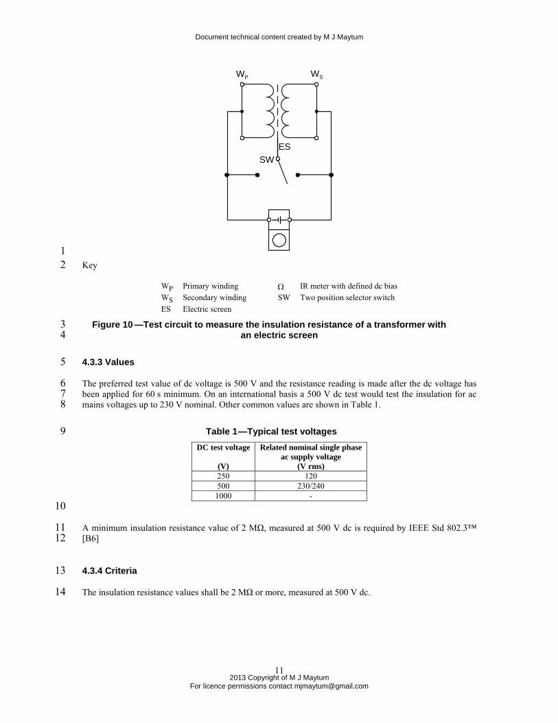
Figure 9 —Test circuit to measure the insulation resistance of a transformer 12 Figure 10 shows the test circuit to measure the insulation resistance of a transformer with an electric screen. 13 Both the primary winding, WP, and secondary winding, WS, are short-circuited. The insulation resistance is 14 measured between the two shorts. Unless otherwise specified, two measurements are taken; once with the 15 selector switch, SW, connecting the electric screen, ES, to the primary winding, WP and once with the 16 selector switch, SW, connecting the electric screen, ES, to the secondary winding, WS. 17
Document technical content created by M J Maytum
2013 Copyright of M J Maytum
For licence permissions contact [email protected]
11
WP WS
ESSW
1 Key 2
WP Primary winding Ω IR meter with defined dc bias WS Secondary winding SW Two position selector switch ES Electric screen
Figure 10 —Test circuit to measure the insulation resistance of a transformer with 3 an electric screen 4
4.3.3 Values 5
The preferred test value of dc voltage is 500 V and the resistance reading is made after the dc voltage has 6 been applied for 60 s minimum. On an international basis a 500 V dc test would test the insulation for ac 7 mains voltages up to 230 V nominal. Other common values are shown in Table 1. 8
Table 1 —Typical test voltages 9 DC test voltage
(V)
Related nominal single phaseac supply voltage
(V rms) 250 120 500 230/240
1000 - 10
A minimum insulation resistance value of 2 MΩ, measured at 500 V dc is required by IEEE Std 802.3™ 11 [B6] 12
4.3.4 Criteria 13
The insulation resistance values shall be 2 MΩ or more, measured at 500 V dc. 14
Document technical content created by M J Maytum
2013 Copyright of M J Maytum
For licence permissions contact [email protected]
12
4.4 Signal transformer voltage-time product 1
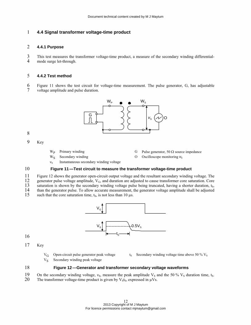
4.4.1 Purpose 2
This test measures the transformer voltage-time product, a measure of the secondary winding differential-3 mode surge let-through. 4
4.4.2 Test method 5
Figure 11 shows the test circuit for voltage-time measurement. The pulse generator, G, has adjustable 6 voltage amplitude and pulse duration. 7
G
WP WS
vS O
8
Key 9
WP Primary winding G Pulse generator, 50 Ω source impedance WS Secondary winding O Oscilloscope monitoring vS vS Instantaneous secondary winding voltage
Figure 11 —Test circuit to measure the transformer voltage-time product 10 Figure 12 shows the generator open-circuit output voltage and the resultant secondary winding voltage. The 11 generator pulse voltage amplitude, VG, and duration are adjusted to cause transformer core saturation. Core 12 saturation is shown by the secondary winding voltage pulse being truncated, having a shorter duration, tS, 13 than the generator pulse. To allow accurate measurement, the generator voltage amplitude shall be adjusted 14 such that the core saturation time, tS, is not less than 10 µs. 15
VS 0.5VS
tS
VG
16
Key 17
VG Open-circuit pulse generator peak voltage tS Secondary winding voltage time above 50 % VS VS Secondary winding peak voltage
Figure 12 —Generator and transformer secondary voltage waveforms 18 On the secondary winding voltage, vS, measure the peak amplitude VS and the 50 % VS duration time, tS. 19 The transformer voltage-time product is given by VStS, expressed in µVs. 20
Document technical content created by M J Maytum
2013 Copyright of M J Maytum
For licence permissions contact [email protected]
13
4.4.3 Values 1
The transformer voltage-time product depends on the transformer size, construction and the Information 2 and Communications Technology (ICT) system. With this degree of variation, it is impractical to create a 3 list of preferred values. As an example, Ethernet transformers typically have a voltage-time product in the 4 50 µVs region. The voltage-time product value can be used to predict the peak secondary voltage level 5 before truncation resulting from a defined surge waveform when there are no secondary voltage limiting 6 components. 7
4.4.4 Criteria 8
The measured value of voltage-time product shall be within the manufacturer’s specified limits. When the 9 manufacturer only gives a typical value, if the measured value is outside ±30 % the typical value, the 10 manufacturer should be contacted to verify the measurement technique and product parameter distribution. 11
5. Ratings 12
5.1 Rating verification 13
A rated value defines either a limiting capability or a limiting condition for a component type. Ratings 14 apply to the component type and, for the ratings in this standard, are maximum values. Ratings are checked 15 by stressing the component at a maximum condition, then measuring specific component characteristics 16 afterwards to verify that the product has not been degraded. Degradation limits may be that the component 17 characteristic values shall not exceed the component type characteristic limits after the stress test or by 18 defining a maximum permitted change of the component characteristic values measured before and after 19 the stress test. Often the component will be monitored during the test to check for any abnormal operation. 20
The temperature and humidity environment for rating verification shall be IEC 60721-3-3 [B16] class 3K1: 21
a) Low air temperature 20 °C ±2 °C 22 b) High air temperature 25 °C ±2 °C 23 c) Low relative humidity 20 % 24 d) High relative humidity 75 % 25
For testing the transformers shall be mounted as specified for the component type. Printed circuit board 26 mounted transformers shall be mounted according to the component type instructions. The circuit board 27 and the printed wiring layout shall be specified. 28
5.2 Rated impulse voltage 29
5.2.1 Purpose 30
This test verifies the insulation rated impulse voltage specified by the transformer manufacturer for the 31 component type. 32

Document technical content created by M J Maytum
2013 Copyright of M J Maytum
For licence permissions contact [email protected]
14
5.2.2 Test method 1
The insulation rated impulse voltage is traditionally tested using a 1.2/50 voltage impulse, see Annex B. 2 Transformer insulation can also be tested with high voltage ac or dc, but these test approaches are not used 3 for the devices and equipment that the transformer is used in as such ac and dc voltages are inappropriate 4 for the electrical environment and can result less stressful testing of the circuit. This standard only specifies 5 insulation impulse testing as it is universal approach that can be used for component, device and equipment 6 port testing. 7
Figure 13 shows the test circuit used for insulation voltage withstand testing. A 1.2/50 impulse generator, 8 whose voltage waveform is monitored by oscilloscope O, has its impulse voltage applied to the insulation 9 separating windings WP and WS. Both the primary winding, WP, and secondary winding, WS, are short-10 circuited. 11
WP WS
O
G
1.2/50 12
Key 13
WP Primary winding G 1.2/50 surge generator WS Secondary winding O Oscilloscope or equivalent monitoring impulse voltage
Figure 13 —Transformer rated impulse voltage test circuit 14 Figure 14 shows the test circuit used for insulation voltage withstand testing. A 1.2/50 impulse generator, 15 whose voltage waveform is monitored by oscilloscope O, has its impulse voltage applied to the insulation 16 separating windings WP and WS. Both the primary winding, WP, and secondary winding, WS, are short-17 circuited. Unless otherwise specified, two measurements are taken; once with the selector switch, SW, 18 connecting the electric screen, ES, to the primary winding, WP, and once with the selector switch, SW, 19 connecting the electric screen, ES, to the secondary winding, WS. 20
21
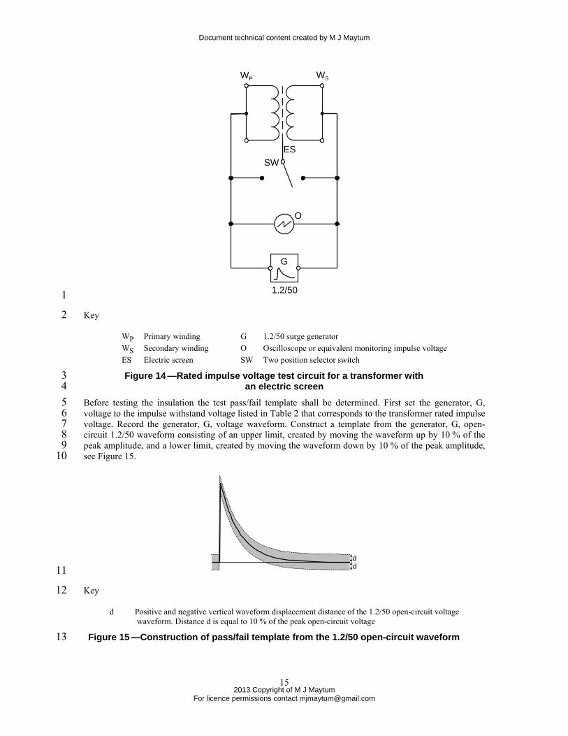
Document technical content created by M J Maytum
2013 Copyright of M J Maytum
For licence permissions contact [email protected]
15
WP WS
ESSW
O
G
1.2/50 1
Key 2
WP Primary winding G 1.2/50 surge generator WS Secondary winding O Oscilloscope or equivalent monitoring impulse voltage ES Electric screen SW Two position selector switch
Figure 14 —Rated impulse voltage test circuit for a transformer with 3 an electric screen 4
Before testing the insulation the test pass/fail template shall be determined. First set the generator, G, 5 voltage to the impulse withstand voltage listed in Table 2 that corresponds to the transformer rated impulse 6 voltage. Record the generator, G, voltage waveform. Construct a template from the generator, G, open-7 circuit 1.2/50 waveform consisting of an upper limit, created by moving the waveform up by 10 % of the 8 peak amplitude, and a lower limit, created by moving the waveform down by 10 % of the peak amplitude, 9 see Figure 15. 10
dd 11
Key 12
d Positive and negative vertical waveform displacement distance of the 1.2/50 open-circuit voltage waveform. Distance d is equal to 10 % of the peak open-circuit voltage
Figure 15 —Construction of pass/fail template from the 1.2/50 open-circuit waveform 13
Document technical content created by M J Maytum
2013 Copyright of M J Maytum
For licence permissions contact [email protected]
16
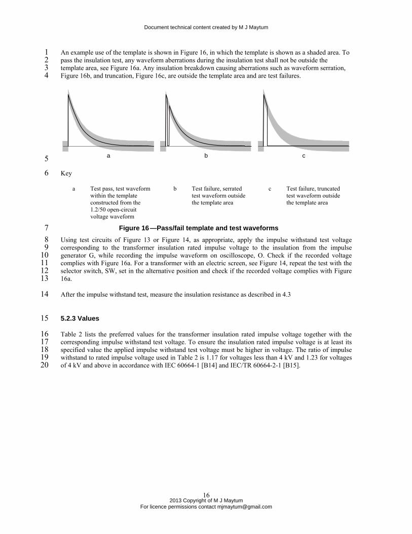
An example use of the template is shown in Figure 16, in which the template is shown as a shaded area. To 1 pass the insulation test, any waveform aberrations during the insulation test shall not be outside the 2 template area, see Figure 16a. Any insulation breakdown causing aberrations such as waveform serration, 3 Figure 16b, and truncation, Figure 16c, are outside the template area and are test failures. 4
a b c 5
Key 6
a Test pass, test waveform within the template constructed from the 1.2/50 open-circuit voltage waveform
b Test failure, serrated test waveform outsidethe template area
c Test failure, truncatedtest waveform outsidethe template area
Figure 16 —Pass/fail template and test waveforms 7 Using test circuits of Figure 13 or Figure 14, as appropriate, apply the impulse withstand test voltage 8 corresponding to the transformer insulation rated impulse voltage to the insulation from the impulse 9 generator G, while recording the impulse waveform on oscilloscope, O. Check if the recorded voltage 10 complies with Figure 16a. For a transformer with an electric screen, see Figure 14, repeat the test with the 11 selector switch, SW, set in the alternative position and check if the recorded voltage complies with Figure 12 16a. 13
After the impulse withstand test, measure the insulation resistance as described in 4.3 14
5.2.3 Values 15
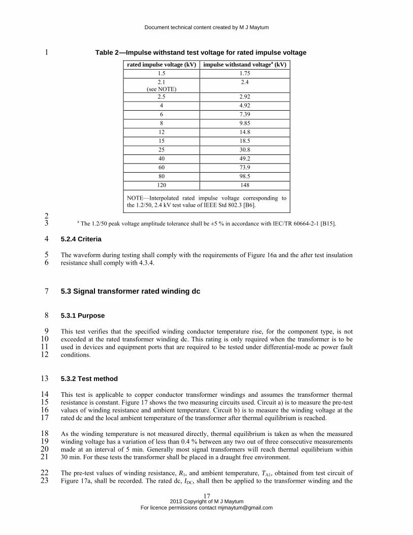
Table 2 lists the preferred values for the transformer insulation rated impulse voltage together with the 16 corresponding impulse withstand test voltage. To ensure the insulation rated impulse voltage is at least its 17 specified value the applied impulse withstand test voltage must be higher in voltage. The ratio of impulse 18 withstand to rated impulse voltage used in Table 2 is 1.17 for voltages less than 4 kV and 1.23 for voltages 19 of 4 kV and above in accordance with IEC 60664-1 [B14] and IEC/TR 60664-2-1 [B15]. 20
Document technical content created by M J Maytum
2013 Copyright of M J Maytum
For licence permissions contact [email protected]
17
Table 2 —Impulse withstand test voltage for rated impulse voltage 1 rated impulse voltage (kV) impulse withstand voltagea (kV)
1.5 1.75 2.1
(see NOTE) 2.4
2.5 2.92 4 4.92 6 7.39 8 9.85 12 14.8 15 18.5 25 30.8 40 49.2 60 73.9 80 98.5
120 148
NOTE—Interpolated rated impulse voltage corresponding to the 1.2/50, 2.4 kV test value of IEEE Std 802.3 [B6].
2 a The 1.2/50 peak voltage amplitude tolerance shall be ±5 % in accordance with IEC/TR 60664-2-1 [B15]. 3
5.2.4 Criteria 4
The waveform during testing shall comply with the requirements of Figure 16a and the after test insulation 5 resistance shall comply with 4.3.4. 6
5.3 Signal transformer rated winding dc 7
5.3.1 Purpose 8
This test verifies that the specified winding conductor temperature rise, for the component type, is not 9 exceeded at the rated transformer winding dc. This rating is only required when the transformer is to be 10 used in devices and equipment ports that are required to be tested under differential-mode ac power fault 11 conditions. 12
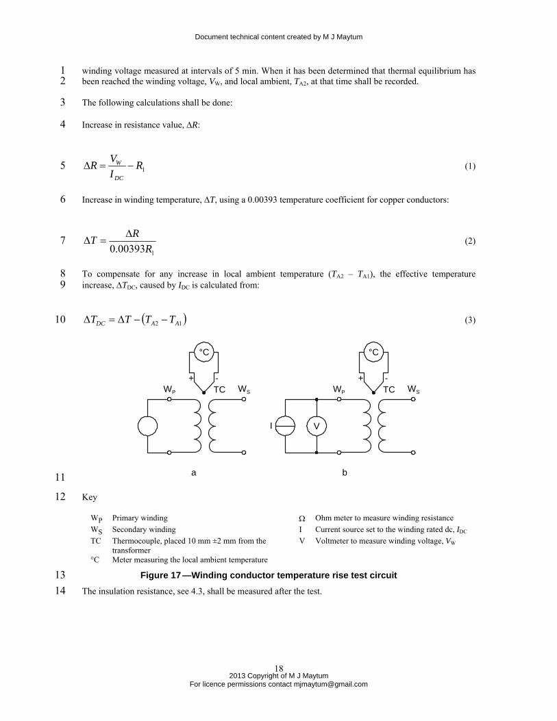
5.3.2 Test method 13
This test is applicable to copper conductor transformer windings and assumes the transformer thermal 14 resistance is constant. Figure 17 shows the two measuring circuits used. Circuit a) is to measure the pre-test 15 values of winding resistance and ambient temperature. Circuit b) is to measure the winding voltage at the 16 rated dc and the local ambient temperature of the transformer after thermal equilibrium is reached. 17
As the winding temperature is not measured directly, thermal equilibrium is taken as when the measured 18 winding voltage has a variation of less than 0.4 % between any two out of three consecutive measurements 19 made at an interval of 5 min. Generally most signal transformers will reach thermal equilibrium within 20 30 min. For these tests the transformer shall be placed in a draught free environment. 21
The pre-test values of winding resistance, R1, and ambient temperature, TA1, obtained from test circuit of 22 Figure 17a, shall be recorded. The rated dc, IDC, shall then be applied to the transformer winding and the 23
Document technical content created by M J Maytum
2013 Copyright of M J Maytum
For licence permissions contact [email protected]
18
winding voltage measured at intervals of 5 min. When it has been determined that thermal equilibrium has 1 been reached the winding voltage, VW, and local ambient, TA2, at that time shall be recorded. 2
The following calculations shall be done: 3
Increase in resistance value, ∆R: 4
1RIVR
DC
W −=∆ (1) 5
Increase in winding temperature, ∆T, using a 0.00393 temperature coefficient for copper conductors: 6
100393.0 RRT ∆
=∆ (2) 7
To compensate for any increase in local ambient temperature (TA2 – TA1), the effective temperature 8 increase, ∆TDC, caused by IDC is calculated from: 9
( )12 AADC TTTT −−∆=∆ (3) 10
WP WS
I V
+ -
°C
TCWP WS
+ -
°C
TC
a b 11
Key 12
WP Primary winding Ω Ohm meter to measure winding resistance WS Secondary winding I Current source set to the winding rated dc, IDC TC Thermocouple, placed 10 mm ±2 mm from the
transformer V Voltmeter to measure winding voltage, VW
°C Meter measuring the local ambient temperature
Figure 17 —Winding conductor temperature rise test circuit 13 The insulation resistance, see 4.3, shall be measured after the test. 14
Document technical content created by M J Maytum
2013 Copyright of M J Maytum
For licence permissions contact [email protected]
19
5.3.3 Values 1
The transformer primary rated winding dc depends on the transformer size, construction and the 2 Information and Communications Technology (ICT) system. With this degree of variation, it is impractical 3 to create a list of preferred values. As an example, Ethernet transformers typically have a primary rated 4 winding dc for 40 °C temperature rise in the 1 A region. The transformer rated winding dc can be used to 5 predict the maximum continuous ac RMS power fault winding current that can be sustained before 6 overcurrent protection is needed. 7
5.3.4 Criteria 8
At the rated dc, IDC, the calculated winding temperature rise, ∆TDC, shall not exceed its specified value. The 9 testing shall not cause a hazard nor result in an insulation resistance lower than specified in 4.3. 10
Document technical content created by M J Maytum
2013 Copyright of M J Maytum
For licence permissions contact [email protected]
20
Annex A 1 2 (informative) 3 4 Bibliography 5
Bibliographical references are resources that provide additional or helpful material but do not need to be 6 understood or used to implement this standard. Reference to these resources is made for informational use 7 only. 8
[B1] J. Wiese, Evolving Ethernet Applications and the Resulting Protection the Resulting Protection 9 Challenges, ATIS 2010 Protection Engineers Group (PEG) Annual Conference, March 16-18, 2010; St. 10 Petersburg, Florida4 11 [B2] J. Wiese, ONT Lightning Damage, ATIS 2011 Protection Engineers Group (PEG) Annual 12 Conference, March 15-17, 2011, Huntsville, AL5 13 [B3] M. Maytum, Lightning Damage of the Home Network Ports, ATIS 2011 Protection Engineers Group 14 (PEG) Annual Conference, March 15-17, 2011, Huntsville, AL6 15 [B4] Tetsuya Tominaga, Damage to equipment in Japan, Technical session on Home Networks, ITU-T 16 Study Group 5 Meeting Geneva, Switzerland, 29 April 2011 17 (http://www.itu.int/dms_pub/itu-t/oth/06/52/T06520000020001PPTE.ppt) 18 [B5] M. Maytum, Damage to equipment in the US, Technical session on Home Networks, ITU-T Study 19 Group 5 Meeting Geneva, Switzerland, 29 April 2011 20 (http://www.itu.int/dms_pub/itu-t/oth/06/52/T06520000020002PDFE.pdf) 21 [B6] IEEE Std 802.3™-2013 – IEEE Standard for Information technology-Specific requirements - Part 3: 22 Carrier Sense Multiple Access with Collision Detection (CSMA/CD) Access Method and Physical Layer 23 Specifications78 24 [B7] IEC 60664-1:2007, Ed. 2.0: Insulation coordination for equipment within low-voltage systems – 25 Part 1: Principles, requirements and tests9 26 [B8] IEC/TR 60664-2-1:2011, Ed. 2.0: Insulation coordination for equipment within low-voltage systems 27 - Part 2-1: Application guide - Explanation of the application of the IEC 60664 series, dimensioning 28 examples and dielectric testing 29 [B9] IEC 62631-1:2011, Ed 1.0: Dielectric and resistive properties of solid insulating materials - Part 1: 30 General 31 [B10] IEC 60065:2011, Ed 7.2 Consol. with am1&2,: Audio, video and similar electronic apparatus - 32 Safety requirements 33 [B11] IEC 60050-151:2001 Ed 2.0: International Electrotechnical Vocabulary - Part 151: Electrical and 34 magnetic devices. 35 [B12] IEC 62477-1:2012, Ed. 1.0: Safety requirements for power electronic converter systems and 36 equipment Part 1: General 37
4 Available as a part of the ATIS Protection Engineers Group - CD Compilation from the the ATIS Document Center (http://www.atis.org/docstore/product.aspx?id=24555) 5 Available as a part of the ATIS Protection Engineers Group - CD Compilation from the the ATIS Document Center (http://www.atis.org/docstore/product.aspx?id=24555) 6 Available as a part of the ATIS Protection Engineers Group - CD Compilation from the the ATIS Document Center (http://www.atis.org/docstore/product.aspx?id=24555) 7 IEEE publications are available from The Institute of Electrical and Electronics Engineers (http://standards.ieee.org/). 8 The IEEE standards or products referred to in this clause are trademarks of The Institute of Electrical and Electronics Engineers, Inc. 9 IEC publications are available from the International Electrotechnical Commission Webstore (http://webstore.iec.ch/?ref=menu). IEC publications are also available in the United States from the American National Standards Institute (http://www.ansi.org/).
Document technical content created by M J Maytum
2013 Copyright of M J Maytum
For licence permissions contact [email protected]
21
[B13] IEC 60617: Graphical Symbols for Diagrams 1 [B14] IEC 60664-1, Ed. 2.0: Insulation coordination for equipment within low-voltage systems - Part 1: 2 Principles, requirements and tests 3 [B15] IEC/TR 60664-2-1 Ed. 2.0: Insulation coordination for equipment within low-voltage systems - Part 4 2-1: Application guide -Explanation of the application of the IEC 60664 series, dimensioning examples and 5 dielectric testing. 6 [B16] IEC 60721-3-3 Ed 2.2 Classification of environmental conditions - Part 3-3: Classification of groups 7 of environmental parameters and their severities - Stationary use at weatherprotected locations 8 [B17] Alan Dower Blumlein, Alternating current bridge circuits, British patent 323,037, 1929 9 [B18] IEC GUIDE 116, Ed. 1.0 Guidelines for safety related risk assessment and risk reduction for low 10 voltage equipment 11 [B19] IEC 61340-1:2012, Ed. 1.0 Electrostatics - Part 1: Electrostatic phenomena - Principles and 12 measurements 13 [B20] IEC 61810-1:2008, ed. 3.0, Electromechanical elementary relays - Part 1: General requirements 14 [B21] IEC 62590, Ed. 1.0, Railway applications - Fixed installations - Electronic power converters for 15 substations 16 [B22] IEC 60060-1 Ed. 3.0, High-voltage test techniques – Part 1: General definitions and test 17 requirements 18 [B23] IEC 60099-4, Ed. 2.1, Surge arresters - Part 4: Metal-oxide surge arresters without gaps for a.c. 19 systems 20 [B24] Andrew R. Hileman, Insulation Coordination for Power Systems, Chapter 9, CRC Press, 1999, 21 ISBN-10: 0824799577 22 [B25] François D. Martzloff, The Propagation and Attenuation of Surge Voltages and Surge Currents in 23 Low-Voltage AC Circuits, IEEE Transactions on Power Apparatus and Systems, PAS-102, May 1983 24
Document technical content created by M J Maytum
2013 Copyright of M J Maytum
For licence permissions contact [email protected]
22
Annex B 1 (informative) 2 1.2/50 Impulse 3
B.1 Introduction 4
Generators delivering 1.2/50 open-circuit voltage impulses at levels given in Table 2 are commercially 5 available. Some generators, called combination wave generators, also deliver a defined 8/20 short-circuit 6 current. Generally 1.2/50-8/20 combination wave generators have a maximum open-circuit voltage of 6 kV 7 peak. 8
B.2 Term definitions 9
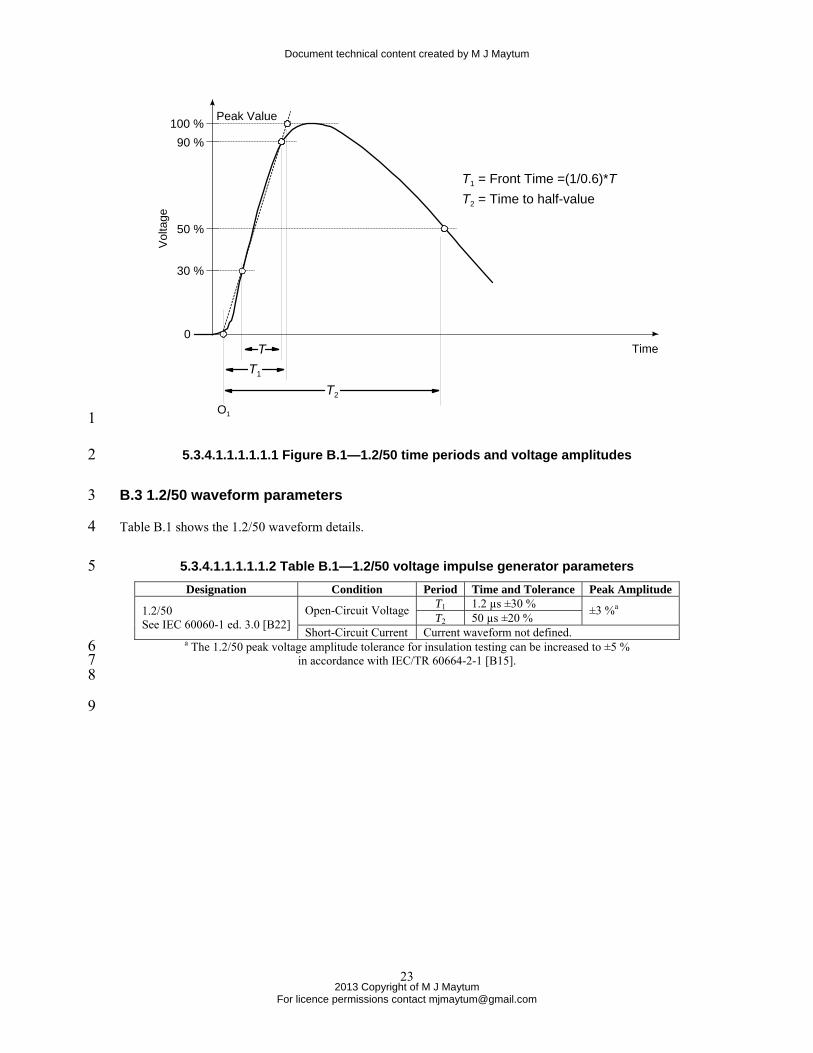
This clause lists the definitions of the terms used in this Annex. Figure B.1 shows the time periods and 10 amplitudes referenced in these definitions. 10 11
virtual front time: the front time T1 of a voltage impulse is 1/0.6 times the interval T between the instants 12 when the impulse is 30 % and 90 % of the peak value 13
NOTE—See Standard IEC 60060-1 Ed. 3.0 [B22] 14
virtual origin; O1: for the impulse voltage waveform, it is the instant at which a straight line drawn 15 through the 30 % and 90 % amplitude values crosses the time axis. 16
NOTE—See Standard IEC 60060-1 Ed. 3.0 [B22] 17
virtual time to half-value; T2: interval of time between the instant of virtual origin O1 and the instant when 18 the voltage or current has decreased to half the peak value 19
NOTE—See Standard IEC 60060-1 Ed. 3.0 [B22] 20
designation of an impulse shape: combination of two numbers, the first representing the virtual front time 21 (T1) and the second the virtual time to half-value on the tail (T2) 22
NOTE 1— It is written as T1/T2, both in microseconds, the sign "/" having no mathematical meaning. 23
NOTE 2— See Standard IEC 60099-4, Ed. 2.1 [B23] 24
10 The reproduction of the IEC copyright terms and definitions from IEC Standards in Database Format are done under the license terms given at http://www.iec.ch/about/copyright/copyright-db_entry.htm
Document technical content created by M J Maytum
2013 Copyright of M J Maytum
For licence permissions contact [email protected]
23
50 %
30 %
90 %100 %
0
Peak Value
Vol
tage
Time
T1 = Front Time =(1/0.6)*TT2 = Time to half-value
T1
T2
T
O1 1
5.3.4.1.1.1.1.1.1 Figure B.1—1.2/50 time periods and voltage amplitudes 2
B.3 1.2/50 waveform parameters 3
Table B.1 shows the 1.2/50 waveform details. 4
5.3.4.1.1.1.1.1.2 Table B.1—1.2/50 voltage impulse generator parameters 5 Designation Condition Period Time and Tolerance Peak Amplitude
T1 1.2 µs ±30 % Open-Circuit Voltage T2 50 µs ±20 % ±3 %a 1.2/50 See IEC 60060-1 ed. 3.0 [B22]
Short-Circuit Current Current waveform not defined. a The 1.2/50 peak voltage amplitude tolerance for insulation testing can be increased to ±5 % 6
in accordance with IEC/TR 60664-2-1 [B15]. 7 8
9