ASSEMBLY, OPERATING INSTRUCTIONS AND … i i ASSEMBLY, OPERATING INSTRUCTIONS AND PARTS LIST FOR...
16
I i i ASSEMBLY, OPERATING INSTRUCTIONS AND PARTS LIST FOR CRAFTSMAN ACCRAaARM 10 INCH RADIAL SAW wMODEL NUMBER 113.29003 The Model Number will be found on a plate attached to your saw, at the left side of the base. Always mention the Model Number in all correspondence regarding the CRAFTSMAN ACCRA-ARM RADIAL SAW or when ordering repair par_. HOW TO ORDER REPAIR PARTS All parts listed herein may be ordered through SEARS, ROEBUCK AND CO. or SIMPSONS-SEARS LIMITED. When ordering parts by mall from the mail order house which serves the territory in which you live, selling prices will be furnished on request or parts will be shipped at prevailing prices and you will be billed accordingly. WHEN ORDERING REPAIR PARTS, ALWAYS GIVE THE FOLLOWING INFORMATION AS SHOWN IN THIS LIST: 1. The PART NUMBER 3. The MODEL NUMBER 113.29003 2. The PART NAME 4. The NAME of Item--RADIAL SAW COAST TO COAST NATION-WEDE, SERVICE FROM SEARS FOR YOUR CRAFTSMAN ACCRA-ARM RADIAL SAW SEARS, ROEBUCK AND CO. and SIMPSONS-SEARS LIMITED in Canada back up your investment with quick, expert mechanical service and genu- ine CRAFTSMAN replacement parts. If and when you need repairs or serv- ice, call on us to protect your invest- ment in this fine piece of equipment. SEARS, ROEBUCK AND CO.- U. S. A. IN CANADA, SIMPSONS_,SEAR5 L_MITED
Transcript of ASSEMBLY, OPERATING INSTRUCTIONS AND … i i ASSEMBLY, OPERATING INSTRUCTIONS AND PARTS LIST FOR...

I
i i
ASSEMBLY, OPERATING INSTRUCTIONS
AND PARTS LIST FOR
CRAFTSMAN ACCRAaARM
10 INCH RADIAL SAW
wMODEL NUMBER 113.29003
The Model Number will be found on a plate attached to your saw,
at the left side of the base. Always mention the Model Number in all
correspondence regarding the CRAFTSMAN ACCRA-ARM RADIAL SAW
or when ordering repair par_.
HOW TO ORDER REPAIR PARTS
All parts listed herein may be ordered through SEARS, ROEBUCK ANDCO. or SIMPSONS-SEARS LIMITED. When ordering parts by mall fromthe mail order house which serves the territory in which you live, sellingprices will be furnished on request or parts will be shipped at prevailingprices and you will be billed accordingly.
WHEN ORDERING REPAIR PARTS, ALWAYS GIVE THE FOLLOWING
INFORMATION AS SHOWN IN THIS LIST:
1. The PART NUMBER 3. The MODEL NUMBER 113.29003
2. The PART NAME 4. The NAME of Item--RADIAL SAW
COAST TO COAST NATION-WEDE,
SERVICE FROM SEARS
FOR YOUR CRAFTSMAN ACCRA-ARM RADIAL SAW
SEARS, ROEBUCK AND CO. andSIMPSONS-SEARS LIMITED in Canada
back up your investment with quick,expert mechanical service and genu-ine CRAFTSMAN replacement parts.
If and when you need repairs or serv-ice, call on us to protect your invest-ment in this fine piece of equipment.
SEARS, ROEBUCK AND CO.- U. S. A.IN CANADA, SIMPSONS_,SEAR5 L_MITED

'CRAFTSMAN ACCRA-ARIVL, |(_INCH RADIAL SAW, MODEL NO. I "_;_._:_003
31
/
a,i iFiguro W
2
FOR PARTS LIST--SEE PAGE 3

CP_SP/L_N ACCP_-AP._ 10_RNCH RADIAL SAW, MODEl. NO. 113.29003
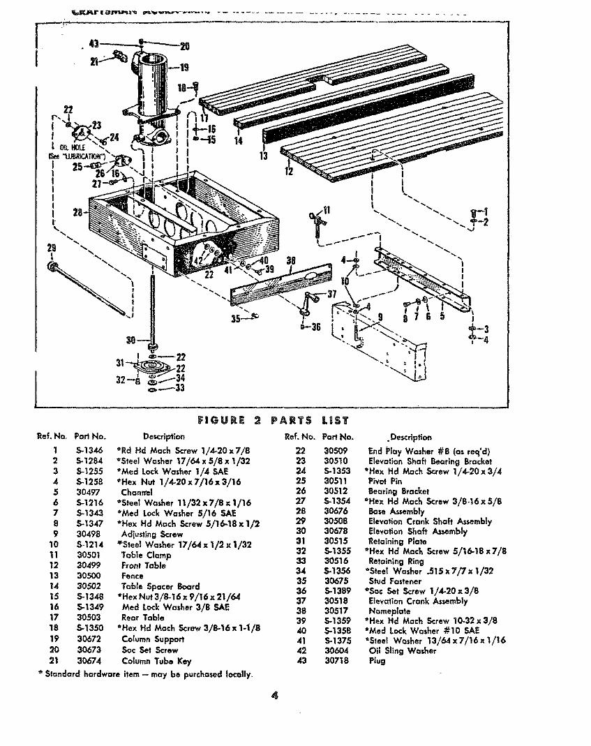
_d_ part_ illu_ted in Figures 1 through 4 and listed under part numbers may be ordered through any Sears mfall orteal! order store. Order parts by mail from the mall order store which serves the territory in which you live. In severalB_'tances part numbers are listed for COMPLETE ASSEMBUESo AI! parts are shipped prepaid w_in the I_m_ of the ¢an_finentol United States.
WHEN ORDERING REPAIR PARTS ALWAYS GIVE THE FOLLOWING INFORMATION:
I. THE PART NUMBER.
2. THE PART NAME.
3. THE MODEL NUMBER 113.29003.
4. THE NAME OF ITEM--RADIAL SAW.
Do not use Ref. Numbers when ordering Repair Parts, always use Part Numbers.
FIGURE I PARTS LIs'r
Ref. No. Part Non
1 30469
2 30470
3 5.1374
,4 30472
5 30473
6 5.602
7 5.1243
8 S-1385
9 30474
10 S-1336
11 5.1255
12 30475
13 5-1337
14 30476
15 30671
16 5-1393
17 5-127
18 30479
19 30661
20 5-1342
21 30662
22 30482
Description Ref. No. Part No.
Adapter Plug 23 5.1266
Cord with Plug 24 30483
_'Pan Hd Type 23 Screw 6-32 x 1/4 25 30484Cord Clamp 26 30485
Cover Plate Assembly 27 30704*Pan Hd Moch ,Screw 10-32 X 3/8 28 30654
_Pan Hd Mach Screw 6-32 x 1/4 29 3065530 30489
_Fiber Washer .140 x _250 x 1/3231 30490
Indicator #I 32 30491
_Fil Hd Mach Screw I/4-28x 1 33 5-t265
*Med Lock Washer I/4 SAE 34 304?2
Radial Arm Cap 35 5-1387_Pan Hd Tyloe B Sheet Metal 5crow
#8 x 3/4"" 36 30493
Radla| Arm 37 5.1216
Column Tube Assembly 38 30494
*Hex Hd Cap screw 3/8-16x3/4 39 9-3240
elnternal Shakeproof Lockwasher 12-2040 30495
Arm Latch 41 3540
Brake Shoe 42 9,3247
*Socket Hd Cap ,Screw 5/16-18 x 5/8 43 9-3220
Arm Lock Screw 44 30496
Arm Lock Pin 45 9.29007
46 9-2536
* Standard hardware ffem -- may be purchased locally."/"Stock item- may be secured through the Hardware Department_ of most Sears
Molt Order Houses.
Description
*Pan Hd Mach Screw 8_32x5/16
Sw_h KeySwitch Cover
SwitchTrim
Arm Latch Shah Assemb|yRetaining Ring
Spring Support WasherArm Latch Spring
Trim C¢_p*Pan Hd Moth Screw 10-32x3/4
Handle
*Truss Hd Mach Screw 1/4-20 x 1-7/8with Lockwasher
Wing Nut
*Steel Washer 11/32 x 7/8 x 1/16Collar
tl0" Kromedge Chisel Tooth SawBlade
Shaft NutArbor Wrench
tDado Set
tMordlng Cutter HeadShaft Wrench
tMotding Cutter Guard
1Work Light
or Slmpsons- Sear_ Retail Stores or
NOTE: Shipping and handling charges for _tandard hardware items (identified by*) such as nuts, s_crew_,washers, etcomake buying these items by mall uneconomical. To avoid sblpptng and handling charges, you may obtain mostof these locally.
lFaGURE
1Ref.Hoe Part No.
1 5-13462 S-12843 5-1255
4 5-t2585 304976 5-1216
7 5-13438 5-13479 30498
10 $-1214
11 3050112 3049913 3050014 3050215 S-1348
16 S-134917 3050318 S-1350
19 30672
20 30673
21 30674
PARTS LIIST
De_r_i:_on Ref. No. Part No,
*Rd Hd Mace Screw I/4-20x7/8 22 30509
_'Steel Washer 17/64 x 5/8 x 1/32 23 30510*Med Lock Washer I/4 5AE 2.4 5-1353
*Hex Nut 1/4-20x7/t6x3!16 25 30511Channel 26 30512
*Steel Washe_ 11/32x7/8_I/16 27 5-1354*Med Lock Washer 5/16 5AE 28 30676
29' 3O5O8*Hex Hd Mace Screw 5/16-18 X 1/2 30 30678
Adjusting Screw 31 30515_Steel Washer 17/64 x 1/2 x 1/32 32 5-1355Table Clamp 33 30516Front Table 34 S-1356Fence 35 30675Table Spacer Board 36 5-1389
_Hex Nut 3/8-16 x 9/16 x 21/64 37 30518Med Lock Washer 3/8 SAE 38 30517Rear Tab|e 39 5-1359
*Hex Hd Mace Screw 3/B-16 x 1-1/8 40 5-1358
Column Support 41 S-1375Sac Set Screw 42 30604
Column Tube Key 43 30718
* Standard hardware item- may be purchased to¢olly_
.Description
End t_lay Washer #8 (as re€I'd)E|evatlon ShaFt Be=rlng Bracket
+He× Hd Moch Screw 1/4-20x 3/4Piv_ Pin
l],earing Bracket_Hex Hd Mace Screw 3/8.16 x 5/8
Base AssemblyElevation Crank Shaft Assembly
Elevation Shaft AssemblyRetaining Plate
+Hex Hc_ Mock Sc_re_ 5116-18x7/8Retaining Ring
tSteel Washer .515 x 7/7 x 1/32Stud Fastener
"Sac Set Screw 1/4-20x3/8Elevation Crank AssemblyNameplate
*Hex Hd Mace S_rew 10-32 x 3/8_Med Lock Washer #10 SAE_'5teel Washer 13/64 x 7/16 x t/16
Oil Sling WasherPlug
4
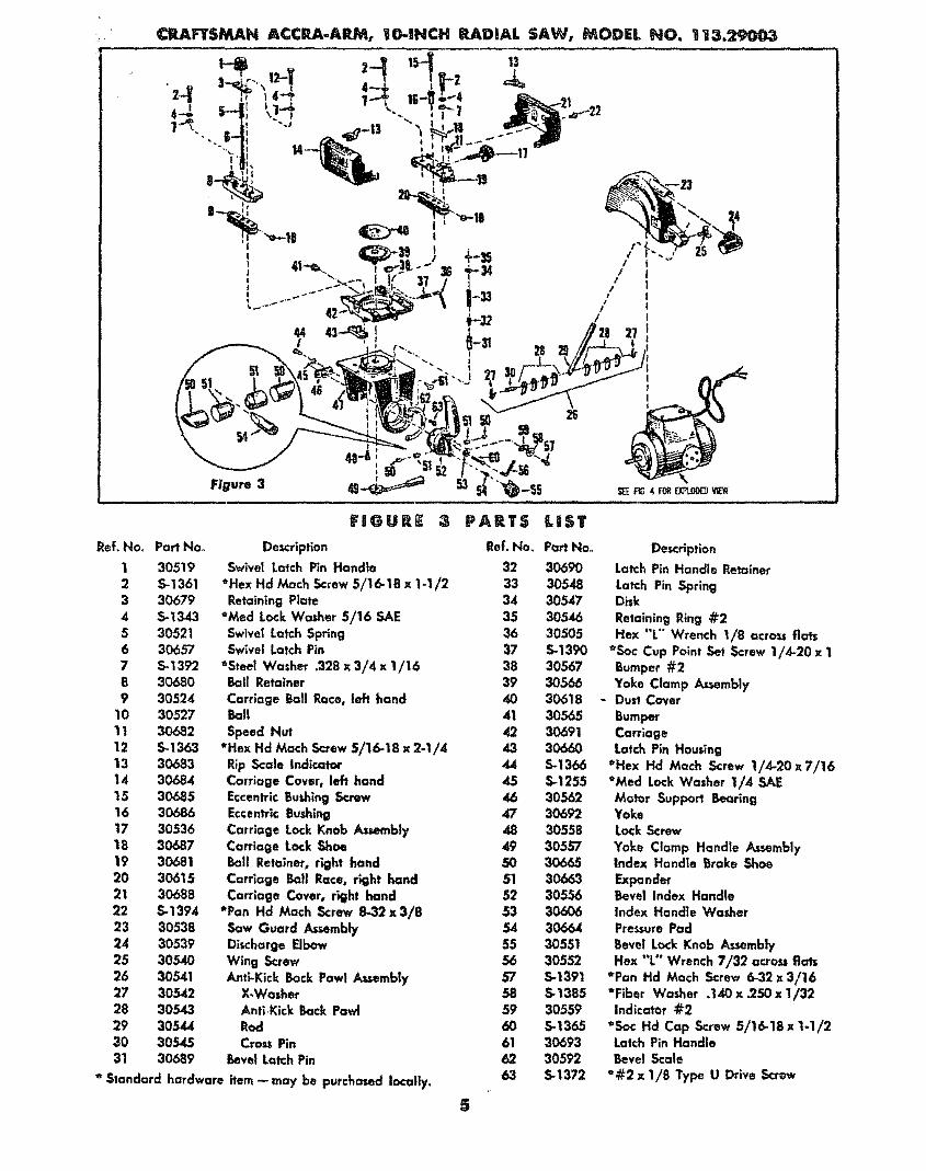
Figure 3 "_-SS........... , u,,,, ,, ,. i i,,,,.............
FIGURS :_ PARTS LIST
Ref. blo_ Part No. Description Ref. No. Part No.
1 30519 Swivel Latch Pin Handle 32 30690
2 5-1361 *Hex Hd Mach 5<:rew 5/16-16 x 1-I/2 33 30548
3 30679 RetainingPlate 34 305474 5-1343 *Med Lock Washer 5/16 SAE 35 305465 30521 Swivel Latch Sp_ing 36 305056 30657 Swivel Latch Pin 37 5-13907 5-1392 *Steel Washer .328 x 3/4 x 1/16 38 30.5678 30680 BailRetainer 39 30566
9 30524 Carriage BallRace, ImP1hand 40 3061810 30527 Ball 41 30565
11 30682 Speed Nut 42 3069112 5-1363 *Hex Hd Math Screw 5/16-18 x 2-1/4 43 30660
13 30683 Rip Scale Indicator 44 5-136614 30684 Carriage Cover, left hand 45 S-125515 30685 Eccentric Bushing Sc.mw 46 3056216 30686 Eccentric Bushing 47 3069217 30536 Carriage Lock Knob Assembly 48 30558
18 30687 Carriage Lock Shoe 49 3055719 30681 Ball Retainer, r'_ghl hand 50
20 30615 Carrlage Ball Race, right hand 51 3066321 30688 Carriage Cover, right hand 52 3055622 5-1394 *Pan Hd Math Screw 8-32x3/8 53 30606
23 30538 Saw Guard Assembly 54 3066424 30539 Discharge Elbow 55 3055125 30540 Wing Screw 56 3055226 30541 Anti-Kick Back Pawl A_.sernbly 57 5-139127 30542 X-Washer 58 5-138528 30543 Anti,Kick Back Pawl 59 3055929 30544 Rod 60 S-1365
30 30545 Crow Pin 61 3069331 30689 Bevel Latch Pin 62 30592
* ,_landard hardware item _ may be purchased locally, 63 5-,1372
Description
Latch Pin Handle Retainer
Latch Pin SpringDisk
Retaining Ring #2
Hex "L'" Wrench 1/8 ocro"_ flats_Soc Cup Point Set Screw 1/4-20 x 1
Bumper #2
Yoke Clamp Assembly- Dust Cover
BumperCorrlageLatch Pin Housing
*Hex Hd Moch :Screw 1/4-20x7/t6_Med Lock Washer 1/4 SA.EMotor Support BearingYokeLock Screw
Yoke Clamp Handle AssemblyIndex Handle _rake Shoe
ExpanderBevel Index HandleIndex Handle WasherPressure Pad
Bevel Lock Knob Assembly
Hex "L" Wrench 7/32 acro. fiats*Pan Hd Math Screw 6-32x3/16_Fiber Washer .140 X .250 x 1/32Indicator #2
*Sac Hd Cap Screw 5/16.18 x 1-1/2Latch Pin HandleBevel Scale
_#2x 1/8 Type U Drive Screw
5

11 12
8 1623 " \\\\IIJ
•..._-_...--20 //
1 1_/BLACKT0 /
GREENTO GREEHON PLUGAND CORD{SEEiTEM3 FiG I)
WHffETO SWFICH=3
BLACKTO SWIICH=1F_gore 4
FIGURE 4 PARTS LiST
Ref. No. Part No. 9".s DescHptlon Ref. No. Part No.__,T_em. Motor (Less Guard Stud) 19 30573
1 30696 Stator Screw 20 5-109
2 5-t367 *Pan Hd Much Screw With Lockwasher 21 305823 30697 Stator .Screw @2 22 306134 30570 Guard Stud 23 30583
5 5-1371 *Steel Washer 1-9/16 x 1-27/32 24 5-1285x .010 (as req'd) 25 30700
6 30571 Bearing 26 5-13697 30572 Bearing Retainer Plate 27 30586O 30719 End Shletd #2 28 30677
9 30574 Hog Ring 29 30588
10 S.1368 *Fiber Washer .380x 9/16,_ 1/32 30 $-137011 30575 Insulating Bushing 31 3070112 30698 Assembled Rotor 32 30590
13 30577 Baffle Plate 33 30619
14 5-1227 *Pan Hd Much Screw 8-32 x 1/415 30578 Cord 34 30702
16 _ Assembled Staler _,'_? None 30670
17 30580 5wing Washer18 30720 End Shield
StanduTd hardware item - may be purchased locally,
"Description
Wire Connector
*Hex Nut 8-32 x 11/32 x 1/8
Shaft CapCard Clamp #2Grommet
*Pan Hd Much Screw 8-32 x 3/8
Capacitor Clamp*Pun Hd Much Screw 6-32 x 5/16
CapacitorProtector
Relc_*Pan Hd Much Screw 6-32 x 7/16Assembled Lead #1
Assembled Lead @2
#16 AWG U.L ApprovedWL,o S-1/2"NameplateOperating Instructions & Parts Listfor Craftsman Aco'ra-Arm 10" RadialSow, Model 113.29003
6
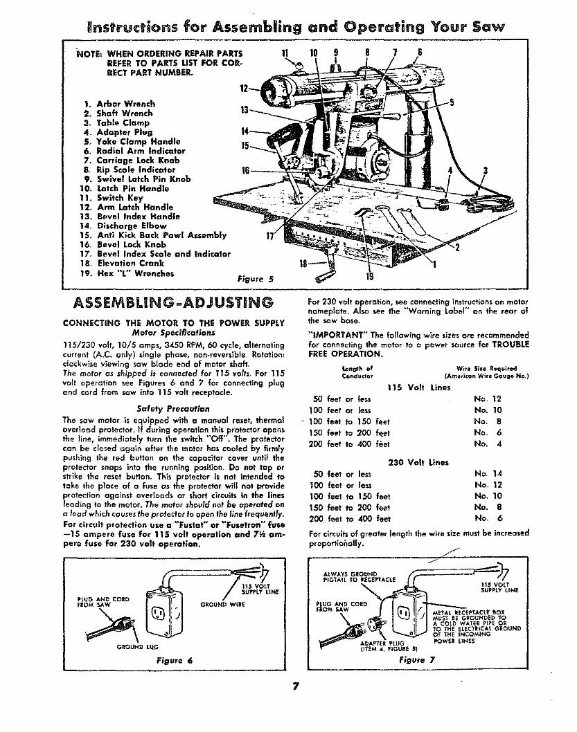
Your
I. Arbor Wrench2. Shaft Wrench
3o Table Clamp4_ Adapter Plug5. Yoke Clamp Handle6_ Radial Arm Indicator
7. Carriage Lock Knob8_ Rip Scale Indicator9. Swivel Latch Pin Knob
10_ Latch Pin Handle11. Switch Key12, Arm Latch Handle13, Bevel Index Handle
14, Discharge Elbow15. Anti Kick Back Pawl Assembly16o Bevel Lock Knob17o Bevel Index Scale and indicator18. Elevation Crank19. Hex "L" Wrenches
Figure 5
ASSEM BLIN G -ADJ USTIN G
CONNECTING THE MOTOR TO THE POWER SUPPLYMotor Spec_cations
115/230 volt, 10/5 amps, 3450 RPM, 60 cycle, alternatingcurrent (AoC. only) single phase, non-reverslbteo Rotation:clockwlse viewing saw blade end of motor shaft.The motor as shipped is connected for 115 volts_ For 115volt operation see Figures 6 and 7 for connecting plugand cord from saw into 115 volt receptacle.
Safety Precaution
The saw motor is equipped with a manual reset, therme]oveHoad protector. If during operation this protector opensthe line, immediately turn the switch "Off". The protectorcan be closed again after the motor has cooled by firmlypushing the red button on the capacitor cover until theprotector snaps into the running position. Do not tap orstrike the reset button_ This protector is not intended totake the place of a fuse as the protector will not provideprotection against overloads or short circuits in the linesleading to the motor. The motor should not be operated ona load which ca usesthe protector to open the line frequently°
For circuit protection use a "Fustat" or "'Fusetran" fuse--15 ampere fuse for 115 volt operation and 7½ am-pere fuse fop 230 volt operation.
PLUa AND CO_D _ _)_ |FROM SAW
GI_OUND LLtO
115 VOLTSUPPLY t|NE
GROUND WtlE
Figure 6
For 230 volt operation, see connecting instructionson motornameptateo Also see the "Warning Label" on the rear ofthe saw base°
"'IMPORTANT" The fat!owing wire sizes ore recommendedfor connecting the motor to o power source for TROUBLEFREE OPERATION.
Length of Wife Size R_quiredConcluctor (Ame_iconWire Gaug_ No,)
115 Volt Lines
50 feet or tess No, 12
100 feet or less No. 10
• 100 feet to 150 feet No, 8
150 feet to 200 f_et No. 6
200 feet to 400 f_et He. 4
230 Volt Lines
50 feet or less No_ 14
100 feet or less Hoe 12
100 feet to 150 feet No. 10
150 feet to 200 feet No. 8
200 feet to 400 feet No_ 6
For circuitsof greater length the wire size must be increasedproporfiohally.
ALWAYSGROUND _--_'_------_'_PIGTAIL TO
115 VOLTSUPPLY LINE
PLUG AND CORDFROM SAW
METAL t_ECEPTACLE _OX"_ MUST _E GROUHDED TO
A COLD WATER PIPE ORTO THE ELECTRICAL GROUNDOF THE INCOM|NG
ADAFTER PLUG POWER LINES_ITEM4, P_GUeES_
Figure 7
7

_OUHTING THE SAW TO A WORK BENCHThe saw should be placed on a _itoble sturdy work benchand posltlor,ed so that the elevation crank (figure B) is fleeto i'otate_ The ba_ of the saw must be mounted to a flat•.urfoce on the work bench to prevent distortion of the saw
ase_The nuts,screws,and washers which attach the wooden_ipping skids to the saw base may be reed to secure thesaw base to the work bench. Check that saw is level or
sloped slightly to the rear so that carriage when undamped,does not run ffwe]y to the front end of the radial arm.
INSTALLATION OF THE TABLE AND FENCE1. Turn elevation crank to robe motor clear of shipping
brackets_2. Remove shipping brackets from base.3o Place front table on channels with notch in table for-
ward and down as shown in Figure 8o4_ Align holes in front table with three forward mount-
ing holes in channels_ See Figure 8.5o Assemble six machine screws and washers through six
holes as shown_6_ Attach six lockwashers and nuts. Before tightening nuts
securely push table evenly toward rear of saw_ Tightennuts.
7, Lay fence in vertical position behind front table.B Lay table _oacer board behind fence.9_ Lay rear table with cut-out section forward behind table
spacer board.10. lnstaff table damps as shown and tighten securely
against edge of rear table.
ADJUSTING THE TABLE PARALLEL TO THERADIAL ARM
1o Remove saw guard with holding washer and wing nut.2_ Remove shaft nut and one loose collar on motor shaft°
See Figure 11.. Insert arbor wrench between collars on motor shaft.
Figure 9. Tighten shaft nut by hand.4. Tighten radial arm handle (item 12, figure 5)_5_ Loosen carriage lock knob (item 7, figure 5) and turn
elevation crank until end of arbor wrench just touchesthe tobte top thus permitting the wrench to be swungback and forth_ See Position 1, Figure 9. Mark this spotand Positions 2, 3 and 4 with a pencil.
NOTE
Do not turn the elevation crank throughout the re-mainder of this procedure as the radial arm mustremain at the same height above the table whilechecking at Positions 1, 2, 3 and 4 of Figure 9,
POSITION
1
POSITION
2
POSITION
3
POSITION
4
Figure 96. Pull motor to Position 2. Wrench when moved back and
forth should just contact table tap as in step 4.7. Turn arm latch handle (item 12, figure 5) counterclock-
wise and pull out. Move arm to Position 3 of Figure 9.Tighten radial arm handle and repeat procedure ofstep 6.
ft. Move radial arm to Pasltlon 4 of Figure 9, tighlen radio|arm handle and repeat above procedure.
If contact between the wrench and the table top is not thesame at all four positions the table can be leveled as fol-lows: (See Figure 10)o
3 1

1_ Loo_n Tne Qamplng _or_w'_ _wn_ mJ _tl _m _€;,nne'ls
• (item 2).2. Adiust nuts (Item 3) by alternating loosening and tighten-
ing so that the channels are moved up or down an thea_justing screws(Item 4) in the desired direction.
3. When channels are properly adjusted the arbor wrenchwifl just contact the table top when swung back and forthat Positions 1, 2, 3, and 4 of Figure 9_ Tighten clampingscrews (Item 1). Recheck the four positions to insure thatno change has occurred.
ATTACHING THE SAW BLADE1. Remove shaft nut and one loose col|arm2. Place saw blade on motor shaft taking care that saw
blade teeth are in some direction asshown in Figure 11_3. Replace other loose coltar and shaft nut° Smooth face
of €ol|or must be away from saw blade.,4. Use arbor wrench (item 1, figure 12 on motor shaft nut
and shaft wrench (Item 2, figure 12) on slot in motor shaftto tighten shaft nut.
CAUTION:SHAFT NUTHAS LEFTHANDTHREADS
To Loosen Shaft Nut" °"_ Figure 11
CAUTION:SHAFT NUTHAS LEFTHAND THREADS
Figure 12
ro TightenShaft Nut
2
Figure 13
:_IUAICII_ UM" :_AW ISI.AU= _ In" IAnLC lur
1. Place edge of combination square or accurate steelsquare on table top and position as shown in Figure 13.Square must be held firmly against table tap°
2. When blade is _uare to the table no light will be v_iblebetween square and face of saw blade. Do not allow
square to rest on saw teeth.If light is visible between steel square and face of sowblade adjust as follows:a. Loosen bevel lock knob (Item I, figure 13). Use 7/32
hex "L" wrench and sllghfly loosen four socket headscrews (item 2, figure 13).
b. Hold motor shaft at one end and tilt motor in properdirection until saw blade is square to table top. See
Step 2 above_c. Retlghten socket head screws (Item 2, figure 13) and
bevel lock knob (Item 1, figure 13).d. Recheck blade _uareness to table top since tighten-
ing of screws may have shifted motor.e. Indicator (item 3, figure 13) should read 0 ° on bevel
index scole_If not, loosen screw and adjust indicator.
Retlghten screw.CHECKING COLUMN TUBE KEYif excessive radla| arm movement is noticed even though the
arm is locked in position, check the fit of the column tubekey (Item 2, figure 14) and the keyway in the column tube.
Figure 14
1. Adjust by loosening the socket set screw (Item I, figure14), using the 7/16 hex "'L'" wrench°
2. Pressvigorously against the rear of the column tube key(Item 2, figure 14) or C-clamp the key while slightlyrocking the radial arm back and forlh. This causes thekey to seat properly in the keyway°
3o Tighten the set screw (item 1, figure 1`4) securely whffemaintaining pressure on the key°
SQUARING THE CROSS CUT TRAVEL TO THE FENCE1_ Set radial arm at 0 ° index position and tighten arm
latch handle_ See Page 11 "Angular Movement andLocking of the Radial Arm" for the most positive and
accurate sewings at an index Posilion,
Figure 15
9

2o Lay combination square or accurate steel square againstfence as shown in Figure 15 and position until it justcontacts a blade tooth (See A, figure 15). Mark this tooth.
3_ When the carriage is moved back and forth on radialarm saw toofi_"A" should iust touch square at all po_itions.
tf saw tooth "A" does not touch square as in step 3, adjustas fellows:
a. If saw tooth "A" (Figure 15) moves away from the squarewhen moving the blade from the rear to the front of thetable, completely loosen the three screws holding thetable to the channel on the |efthand side of the table
_nd slightly loosen those on the right side of the tableoSlightiy tighten the left table clamp (Item 1, Position 4,Figure 9)_
bo Tighten all table screws first, then both table damps.Recheck blade squareness again.
c. Reverse this procedure if tooth "'A" moves into the squarewhen moving the saw blade from the rear to the frontof the table.
tn some cases, the above adjustment may not be sufficient.if this is the case, adjust as follows:_. Remove three screws (Item 1 and 2, figure 16), indicator
(Item 3) and radial arm cap (Item 4).b_ Turn arm latch handle 1/2 turn counterc!ockwi_ to re-
lease brake, Do not pull out_c. Slightly loosen (do not remove) two hex head screws
(Item 5) inside of column tube,do Move radial arm in proper direction to make saw tooth
"'A" (Figure 15) follow edge of square when checking.e. Retightee hex head screws (Item 5, figure 16) and arm
latch handte.f. Recheck blade tooth "A" travel with square.g_ After blade is square to fence reassemble radial arm
cap and indicator using screws (item 1 and 2, figure 16).Set indicator at 0 °.
PRELIMINARY CROSS-CUT AT THE 0 _ POSITION
1o Attach saw guard (Item 1, figure 17) washer (item 2) andwing nut (Item 3) to motor and motor s_tud(Item ,4).
2. Pull motor forward of fence so that blade is flee to rotate°3. Lower radio1 arm untff sow blade just clears table top.,4. Tighten carriage lock knob (Item 5, figure 17).
CAUTION
Before cutting always be sure that the arm latchhandle is locked fully clockwlse. (Item 8, figure 17.)
5. Plug in power cord to receptacle.6. Insert switch key (Item 6, figure 17) and turn "On".7. Lower rodial arm until blade cuts into tabte top 1/32".
THIS tS ALL THAT IS NECESSARY°
To cut a blade clearance groove in the table and fence holdthe bevel index handle (item 7, figure 17) with the left handand loosen the carriage lock knob (Item 5, figure 17) withhe right hand. Slowly pull the motor with the left hand out
to the e_reme end of travel and then push the motor backthrough the fence to the e_treme rear posltion_Turn the keyJwitch "OFF",
Figure 17
CHECKING THE SAW BLADE FOR HEEL(LEFT AND RIGHT)
Using a scrap piece of one-lnch lumber approximately sixinches wide, lay it on the table against the fence on the leftside of the blade. Position the board ta permit a three-inchpiece to be cut from the right end holding the beard firmlyagainst the fence wffh the left hand. Turn the key switch"On" and commence the cut by pulling the saw forwardthrough the board until the front half of the saw blade clear_as _hown in View A_ Turn the switch "Off" and atlow the
saw blade to come to a complete _op while the rear portionof the blade is r_itl in contact with the wood, Marks on theface of the board indicate left heeling. Check face of cut
board. See View A_ To check for right beefing repeat thesame cut from the right side of the blade. Check for heelmarks° See View B.
NOTE
The piece of wood must be held firmly against thefence and not permitted to move while the sawblade is coming to a stop°
_0 "r_VEL ,_OE _U_VEL
%.
/_LnK IN DOA_O _'_ :ll_''' ktAf_ IN _AIO
St,ADE HEELING _ _ BLADE HEELINGTO LEFT VIEVV A V|_ B. TO li:IGHr
Exaggerated View of Heeling Condition
To correct for heeling (left or right) proceed as fallows:1o Remove left hand carriage cover (Item 1, figure 18)o
Figure 1 8
10

2.* Loosen yoke clamp handle (item 2, figure 18) by pullingthe. handle horizontally toward the front of the saw.
3. Slightly loosen the two hex head machine _rews (item 3,figure 18).
4. Rotate the yoke (item 4, figure 18) very slightly oppo_iteto the direction of heel. (For left heel, rotate yoke clock-wise;forrightheel rotateyoke counterclockwise.)
OPERATING1. Arbor Wrench2. Shaft Wrench3_ Table Clamp4. Adapter Plug (Except in Canada)5o Yoke Clamp Handle6. Radial Arm Indicator7. Carriage Lock Knob
8. Rip Scale Indicator 14----.._9. Swivel Latch Pin Knob
10. Latch Pln Handle1 Io Switch Key12. Arm Latch Handle13_ Bevel Index Handle14_ Discharge Elbow15. Anti Kick Back Pawl Assembly16. Bevel Lock Knob17. Bevel Index Scale and indicator18. Elevation Crank19. Hex "'L" Wrenches
5. Refighten the two hex head machine screws (item 3,figure 18) and relock the yoke by pushing the yoke clamphandle toward the rear of the saw.
6. Recheck for left and right heel as before.7o When the heeling condition is corrected the face of the
board will shaw no marks when cut from either sideof the blade.
B° Replace carriage cover_
CONTROLS
NOTE: WHEN ORDERING REPAIR PARTSREFER TO PARTS LIST FOR COR-RECT PART NUMBER. Figure _9
RAISING AND LOWERING THE RADIAL ARM is ac-
complished by the elevation crank (Item 18, figure 19). Onecomplete turn of this handte will raise or lower_the radial€l/'m _,_".
LOCKING THE CARRIAGE TO THE RADIAL ARM isaccomplished by the carriage lock knob (Item 7, figure 19).Turn the knob clockwise to lock; counterclockwise to unlock.
ANGULAR MOVEMENT AND LOCKING OF THE RADIAL
ARM are controlled by the arm latch handle (item 12,figure 19). The radial arm can be rotated 360 ° and lockedin any position. The arm is unlocked from any position by aslight counterclockwise rotation of the arm latch handleand is locked in any position by rotating the arm latchhandle clockwise until tight. The radial arm has positivestops at 0 ° and 45 ° left and right, and is released fromthese index positions by unlocking and pulling out the armlatch handle (Item 12, figure 19). Due to positive armlocking at the index positions, the arm latch handlemay be difficult to pull out. A few turns to the left willrelease i|.
For most positive and accurate settings at the index posi-tions, the following is recommended:1. if the radio1 arm is already indexed, unlock and pull
out the arm latch handle and move the radial arm off
of the index position. Release the arm latch handle.2. Before moving the radial arm to the desired index posi-
tion, turn the arm latch handle (item 12, figure 19) just1/4 turn counterclockwise from the locked position.
3. Move the radia! arm into the index position (do notbump or jar) and hit the face of the arm latch handlesolidly with the palm of the hand.
4. Lock the radial arm by turning the arm latch handle tuftyclecl_,vise.
CAUTION: When moving the radial arm in anydirection beyond _° left or right, always pull out
11
the arm latch handle (at end of radial arm) to
prevent damaging the arm lock pln_ If damageoccurs, the radial arm wiff not index properly at0 ° and 45_ left or right.
MOVEMENT AND POSITION OF THE MOTOR IN THE
YOKE are,controlled by the latch pln handle (item 10, figure19) and beveZlock knob (Item 16, figure 19). The bevel scaleindicates the angular position of the motor with respect tothe horizontal from 0 _ to 90 ° in either vertical pos'rtionoThelatch pin handle automatically indexes the motor at 0 °, 45 °,and 90 ° up and da'_n. Lift to release. At any other posi-tion the latch pin handle isnot engaged. The bevel lock knoblocks the motor to the yoke when the motor is in any posi-tion. Locking is clockwise; unlocking is counterclockwise.MOVEMENT AND POSITION OF THE YOKE are con-
troffed by the swivel latch pin knob (Item 9, figure 19) andthe yoke clamp handle (Item 5, figure 19). The swivel latchpin automatically indexes the yoke at each 90 ° position andtwo 45 ° positions_ Lift to release_ The yoke clamp handlelocks the yoke to the carriage in any position. Pull to release.Push to tighten. When "in Ripping" it may be desirable tohave more flee table in front of the saw blade than is oh-tainable when the radial arm is at the 0 ° posltlon_ Withthe blade in th normal cross-cut position index the radialarm to 45 ° left and lock it. Then loosen the yoke clamphandle and index tile yoke 45 ° clockwise_ Redamp the
yoke clamp handle. The added free table space is now tothe right of the blade and ripping should be done from theright side of the table. The reverse is also true for "OutRipping" by indexing the radial arm 45 ° right and index-ing the yoke ,45° countercTackwlse_ The added table spaceis now ta the left of the blade and ripping should be donefrom the left s_de of the table.
CAUTION: Under these two conditions the In-Rip
and Out-Rip scales cannot be used.
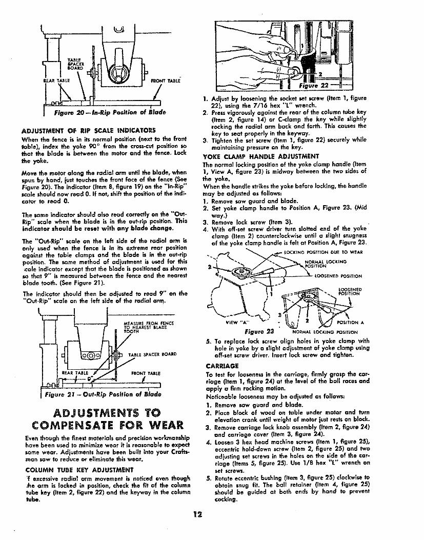
ADJUSTMENTOF RiPSCALEINDICATORSWhenthefenceis in itsnormalposition(nextto thefronttable),indextheyoke90 ° from the €_oss-cut position sothat the blade is between the motor and the fence° Lock
Move the molar along the radial arm uoti_ the blade, whenspun by hand, just _uches the front face of the fence (SeeFigure 20)° The indicator (Item 8, figure 19) on the "In-Rip"scale should now read 0. If not, shift the position of the indi-ca|at to read 0.
The same indicator should also read correctly on the "'Out-Rip" scale when the blade is in the out-rip positlon_ Thisindicator should be reset with any blade change.
The "Out-Rip" scale on the left side of the radial arm isonly used when the fence is in its extreme rear positionagainst the table clamps and the blade is in the out-rlpposition. The some method of adjustment is used for thiscote indicator except that the blade is positioned as shownso that 9°° is measured between the fence and the nearestblade tooth. (See Figure 2I).
The indicator should then be adjusted to read 9" an the"Out-Rip" _cale on the left side of the radial arm_
hEAR T,/_ LEg._
MEASURE FROM FENCETO NEAREST BI.J_DETOOTH
I
Figure 21 .-Out-Rip Position of Blade
ADJUSTMEHT$ TOCOMPENSATE FOR WEAR
Even though the finest materials and procidon workmanshiphave been u_ed to minimize wear it is reasonable to expectsome wear. Adjustments have been built into your Croft_man sow to reduce or eliminate this wear.
COLUMN TUBE KEY ADJUSTMENT
:f excessive radlat arm movement is noticed even though,t_e arm is locked in position, check the fit of the columntube key (item 2, figure 22) and the key'way in the columntuber
Figure
1. Adjust by loosening the socket set screw (item I, figure22), using the 7/16 hex "t" wrench.
2. Prexs vigorously against the rear of the column tube key(Item 2, figure 14) or C-clamp the key while slightlyrocking the radial arm back and forth_ This causes thekey to seat properly in the keywoTo
3, Tighten the set screw (Item 1, figure 22) securely whilemaintaining pressure on the key.
YOKE CLAMP HANDLE ADJUSTMENT
The normal locking position of the yoke clamp handle (item1, View A_ figure 23) is midway between the two sides ofthe yoke.When the handle strikesthe yoke before locking, the handlemay be adjusted as follows:1. Remove sow guard and blade.2. Set yoke clamp handle to Position A, Figure 23. (Mid
way.)3. Remove lock screw (Item 3).4o With off-set screw driver turn slotted end of the yoke
clamp (Item 2) counterclockwise until a slight snugnessof the yoke clamp handle is felt at Position A, Figure 23.
a___s G _osmoN ou_ To WEARNOR/€_ L LOCKING
1710N
..-..3._ LOOSENED _SITION
_ "" LOOSENED
POSitION A
Figure 23 NO_U,_,_OC_NGPOSlnON
5o To replace lock screw align holes in yoke clamp withhole in yoke by a slight odiustment of yoke clamp usingoff-set screw driver° Insert lock screw and tighten.
CARRIAGE
To test for loosenessin the carriage, firm|y grasp the car-riage (Item 1, figure 24) at the levet of the baff races andapply a firm rocking motion.Noticeable looseness may be adiusted as follows:
1. Remove sow guard and blade.2o Place block of wood on table under motor and turn
elevation crank until weight of motor just rests on block.3. Remove carriage lock knob assembly (Item 2, figure 24)
and carriage cover (Item 3, figure 24).4. Loosen 3 hex head machine screws (item 1, figure 25),
eccentric hold-down screw (Item 2, figure 25) and two
adjusting set screwsin the holes on the side of the car-riage (Items 5, figure 2S)o Use 1/8 hex "L" wrench onset screws,
5_ Rotate eccentric bushing (Item 3, figure 25) clockwise toobtain snug fit. The bali retainer (Item 4, figure 25)should be guided at both ends by hand to preventcocking°
12

6. Retlghten all hex head scTew and _ntric bold-down_rew. (Do not allow eccentric bushing to rotate when
ttlghtenlng.)7. Correct adjustment exists when there is no play between
the carriage and radial arm, and yet the carriage movesfreely. After adjustment is completed snugly tighten thetwo adjusting set screws. Caution: Do not o_rtlghten.
8. Replace carriage cove_ and lock knob ossernbly_
PROPEROPERATINGPROCEDURESDRESS PROPERLY -- Operation of the saw is simple, safeand easy-when properly done. Always be atert_ Do notwear a tie or other loose artlcles. Keep long sleeves downwith cuffs fastened or wear short sleeves. NEVER STOP
BEING CAREFUL. One moment of inattention can cost youa painful injury.
AVOID AWKWARD HAND POSITIONS-*Do not gethands into a position in which a sudden slip can cause themto move into the saw blade. NEVER OPERATE THE SAWWITH THE ARMS IN A CROSSED POSITION. Never holdwork on right side of blade with left hand while pulling sawwith the right hand Do not attempt flee-hand cros_.cuttlngoUse a push stickwhen hand gets too close to the blade in oripping position.
NEVER TWIST WORK --Twisting work will bind blade andcause a kickback_
Safety Precaution
The motor is shipped with a shaft cap (Item 21,figure 4) threaded onto the stub end of the motorshaft_ When this shaft end of the motor is not beingused, this cap should always be in place.
LUBR|CATriONYour saw is a fine machine and should be given the best ofcare. If kept clean and properly lubricated, it will give manyyears of trouble-free service° Before describing the variouspoints which may periodically require lubrication, IT 15MORE IMPORTANT TO FIRST MENTION THE VARIOUSSPOTS WHICH SHOULD NOT BE LUBRICATED°
NO LUBRICATION REQUIRED
Do not lubricate any ball races or any ball bearings.
Do not lubrTcate bearing fit of bevel index handle (Item 52,figure 3) in yoke.
Do not lubricate the motor bearings° These are sealed ballbearings and require no added lubrication.
Do not lubricate bevel latch pin (Item 31, figure 3) in yoke.
DO not lubricate between radial arm cap (Item 12, figure 1)and radial arm_
PERIODICALLY LUBRICATE THESE POINTSUse SAE No. 10-30 Auto Engine Oilo
Apply a few drops of all along the swivel latch pin (item 6,figure 3) only ff the pin has a tendency to stick.Remove theleft-hand carriage cover and use all sparingly to prevent itfrom getting on the ball bearings or races.
A light film of oil can be wiped on the face of the columntube (Item 15, figure 1) and keyway to lubricate the fitbetween this part and the key and column support (Items21 and 19, figure 2).
Apply a few drops of all to the bearing surfaces of theelevation crank shaft assembly (Item 29, figure 2). An othnghole is provided in the elevaffon shaft bearing bracket (Item23, figure 2) to facilitate the lubrication of the rear bearingsupport.The thread on the elevation shaft assembly (Item 30, figure2) can be lubricated through the oiling hole in the centerof the radial arm cap (Item 12, figure I).
STANDARDSAW OPERATIONSCROSS, CUI"rlNGCrass-cuttlng is the sawing of wood across the grain. Planksore milled with the grain running the length of the plank_ Ifa straight cross-cut is desired, the board is placed on thesaw table against the fence so that the grain is parallel tothe fence. See Figure 26.
NOTE
When cross-cuttlng normal pieces of lumber, thelong end of the board should be placed to the leftof the saw blade as the board is normally held bythe left hand during operation_
The radial arm must be positioned at 0 ° as indicated by theradial arm position indicator. The arm latch handle must beindexed and tightened_ See page 11 "Angular Movementand Locking of the Radial Arm" far the mostaccurate settingat the 0 ° index position. The yoke must be indexed at the 0 °position, making the saw blade perpendicular to the ripfence, and the yoke clamp handle placed in the locked pos_-
• .. o €ISfion. The bevel index handle must be positioned at 0 ,indicated by the bore| scale, and Iocked_ Turn the elevationcrank to lower the saw until the btade teeth are approxl-mately 1/32" below the table surface in the saw slotmade when performing the "PREI.IMINARY CROSS-CUTAT THE 0 ° POSITION". Push the saw carriage to the rearof the radial arm so the blade is behind the rip fence. Adjustthe saw guard so the bottom is parallel to the table and setthe antl-klckback pawl assembly so it iust clears the boardto be cut. Turn the switch key "On" to start the saw motor.Hold the board firmly against the rip fence with the left handand grasp the bevel index handle with the right hand. Thecut is then made by pulling the carriage forward until the
13

saw _lode cuts through the work_The carriage will tend to move toward the operator so be,prepared to restrain it by keeping your arm straight fromfife shoulder to the wrist, When the cut is complete, the sawshould be returned to the back of the radial arm and theswltch key turned "Off". it will be noticed, that thesaw blade tends to feed itself through the workdue to the rotation of the blade and the direction offeed. Therefore, the operator should develop the habitof holding his right arm straight from the shoulderto the wrlst_ After this method is used a few times the oper-ator will find that it is necessary to roll or rotate the bodyfrom the waist up. If this method is followed, it will becomeapparent that very little effort is required on the pert of theoperator to move the saw blade through the work, and inmostcases, the right arm is used merely to control the rate offeed of the saw through the board_ It will also be found thatwhen cross-cuttlng a thick board itwilt be necessary to retardmovement of the saw through the work. By holding the rightarm (right hand normally grips the saw handle) _alght, theoperator can easily control the rate of feed, thusprever_ingthe saw blade from overfeeding and stalling the saw motor.This mustbe avoided whenever possible. In some casesit maybecome necessary to cross-cut tong boards which extendover the saw table on one, or both sides. This can causebuckling of the board and bind the sow during the cut, Toeliminate th;s condition the ends of the board should be sup-
ported. Figure 27 illustrates a typical support which can bemade and used to facilitate cross<utting of long lumber°
RIPPING
Ripping is the sawing of wood with the grain. It is alwaysdone with the help of the fence as a guide to position andmaintain the work at the correct width for the cut_ Becausethe work is pushed along the fence, it must have a reason..ably straight edge to make sliding contact with the fence°Also, the work must make solid contact wlth the table sa thatit will not wobble or rock. Provide a straight edge, even ifthis means temporary nailing of an auxiliary straight edgeboard to the work_ If work piece is warped, torn the hollowside down.
Use of the sow guard is always recommended; and the arrti-kicEback paw! assembly shou|d always be used in both in-ripor our-rip operations, Before ripping and after the saw hasbeen positioned prior to cutting, the saw guard and anti-kickback pawl assembly must be properly adjusted_ Loosenthe wing nut holding the guard to the motor and lower thenose of the guard to within _" above the top surface ofthe board to be cu_. Refighten the wing n_ securely.
CAUTION
The nose of the guard refers to that end of theguard which is opposite to the end which mounts theanti-kickback pawl assembly. Always rlp from thenose of the guard. See Warning [.abel on guard.
At the opposite end of the guard, loosen the wing screwholding the anti-kickback pawl assembty and lower theassembly until the tips of the pawls are 7/8" below the top_Jrface of the board to be cu/_ Retighten the wing screw
IN-RIPPING--In-rip refers to a posltion when the blade isbetween the motor and the fence and parallel to the fence.See Figure 28. To place the sow in this position, unlock theyoke, disengage the swivel latch pin and rotate the yoke 90 °clockwise (viewing it from the carriage) until the swivel latchpin automatically indexes the yoke 90% Relock the yoke.See "'Adjustment of Pointers" to check accuracy of "lnoRip"scale reading. Position the motor on the radial arm until thepointer on the "In-Rip" scale indicates the desired width ofthe finished cut board_ Tighten the carriage lock knob se-curely. Position the discharge elbow on the guard _o thatsawdust will be blown toward the rear of the saw. Turn thesaw "'On" end lower the saw blade until it cuts into the table
top about 1/32",, Turn the saw "Off"° Haw adjust thesaw guard and anti.kickback pawl assembly as describedin the paragraph "Ripping". The board to be rippedmust be fed into the saw blade from the right side ofthe table, therefore, the normal position for the operatoris also at the right side of the table. With the left hand safelyclear of the blade and holding the board to be ripped downagainst the table and against the face of the fence as aguide, use the right hand to feed the board into the saw. Theleft hand should remain stationary, serving as a guide only.As the right hand approaches the left hand, hold a push stickwith the right hand to complete the cut°Do not leave a longboard unsupported so that the spring of the board causes itto shift on the table_ A support like that described in "Cross_Cutting" can be used to support the board behind the blade;and if the board is very long, use another support in front ofthe saw° R_pped boards up to 8_" wide can be cut inthe In-Rip posltiom
OUT-RIPPING-_Ouf_rip refers to a position when the motoris between the blade and the fence° Normally, this positionis only used when the width of the required ripped boardcannot be cut from the in-rip position. Ripped boards up to181,_°' wide can be cut in the out_rlp position when thefence is against the front table. If the fence is moved to theextreme rear position against the table clamps, rippedboards up to 25,%" wide can be cut_ To place the sawin the out.rip position, the yoke mustbe rotated and indexed90 ° counterclockwise from the crossocutposition and locked..The same procedure far sawing is used except that nowthe operator stands at the left side of the table and a pushstick is normally nat required°
NOTE
For added table space in front of the blade see"Movement and Position of the Yoke".
F;gure 27 Figure 2B Figure 29
14

RESAWING
Resowing is the cutting of thick boards into thinner ones_ Itis a ripping operatiano See Figure 29. Smalt boards-up to2½" maximum wldth--can be resawed in one pass; butlarger boards up to S" maximum require two passes,one pass along each edge of the board.r When two cutsfrom opposite edges are required, these should be madeto overlap _,_" from the approximate center of the board_If the first cut is too deep, the kerf will close and bind thesaw an the second cut, with danger of kickback° Also, whenthe kerf closes, the two sides of the cutare na longer parallelto the saw blade, and the saw will cut into them to spoiltheir appearance_ Keep the same face af the board againstthe fence when making both cuts.
When cutting boards thicker than 4"° a fence should be usedwhich extends 3½" above the table topr When cuttingboards thicker than 5", cut both sides and finish the cutwlth a hand saw_
BEVEL AND MITER CUTS
Bevel cuts can be made from either a crass-cuttingor rippingposition by tilting the blade to the desired angle. Miter cutscan be made only from a cross-cutting position when theblade and radial arm are at some angle other than 90 = tothe fence° A bevel miter cut is a cut which is both beveledarid mitered. This cut is made with the blade and radial armset at the desired miter angle to the fence and then the bladeonly is tilted with respect ta the table top to the desired beve!angle. This cut is also referred to as a compound miter, SeeFigure 30_
USE OF THE DADO HEAD
The dado saw or head, as it is called, is a special set ofblades for cutting grooves and dados_ Craftsman 8" Krom.edge Dada Set can be purchased at any Sears Retail Storeor Mall Order House. The head consistsof two autside bladesI/8" thick, six 1/8" thick chipper blades and Paper wash-ers for' 1/t6" width adjustments. With these blades, groovesof 1/8", 1/4", and additional widths increased in steps of1/t6" up to a maximum of 13/16" wide can be cut. Outsideblades con be used alone, chippers cannot°
When using the moxlmum width of dado of 13/16" onthe motor shaft, the outside Ioo_e collar (Item 38, Figure 1)must not be used. The width of the dado can be reduced
while using the loose collar and two or more passes can bemade with the work to obtain the desired width of cut°
Whenever two or more chippers are used, stagger the cut-ting ends as evenly as possible around the clrcumference_Fractlanat adjustments in thicknessof the head can be madeby using paper washers between the outside blades andchippers° Dado head operations are much the same as thosewith a standard blade-but the dado head takes a biggerbite, so that the work-place should be held more firmly.When a groove wider than the dado head is needed, make
Figure 31 Figure 32
two or mare passes_Space cuts so that they oveddp a trifle.Dado work is done in the cross-cut position. Ploughing isdone in the ripping position. If the rip or plough position isused the saw guard and anti-kickback pawl assembly shouldbe adjusted as described in the paragraph "RIPPING". Rab-beting is done in the vertical position. See Figure 31. Whenrabbeting, the motor is indexed 90 ° to the vertlcat positionso that the blades are between the table tap and the motorand the yoke is indexed 90 oclockwise and locked° The sow ismoved back on the radio1 arm and locked to the arm whenthe amount of the blade extending forward of the fence isequal to the depth of the rabbet desired, tf the depth of therabbet is large, do not attempt to cut it in one operation.Lower the radial arm until the blades are in a position to cutthe desired width of rabbet in the edge of the board, Thebottom of the saw guard should be parallel to the fence andthe discharge elbow directed to the rear of the sown
MOLDING OR SHAPING
Th_swork is done using the Craftsman Molding Cutter Headand a set of cutters depending on the type of molding cutdesired. This work is done with the saw in the some positionas that described for rabbetlng_ See Figure 32. Since theposition of the cutters with respect to the fence and thetable top can be adjusted any or all of the cutter shapescan be used.
ROUTING AND DOVETAILING
Routing and dovetailing are done with the motor indexedand locked 90 ° from the horizanta! except that this timethe externally threaded stub end opposite the normal bladeend is between the "motor and the table top. The foffow-ing chucks will mate with this external ½-20 thread: (SeeFigure 33)°
0 '° to 1/,_" Key Chuck5/64" to I/2" Key Chuck
The followlng routers and dovetails are recommended:
1/8" muter1/4'" router3/8" router1/2" router5/8" router3/8" dovetail1/2 °° dovetoff
Figure 33
Routing may be done by either moving the work wffh astationary router or by clamping the work to the table andmoving the router. Always approach the router bit from theleft hand side af the saw.
15

Figure 25 Figure 36
BOiUNG
Your saw can also be €onveded 1o a horZzonta| drill forboring by using one of the recommended c_ucks ahd theproper drill For drilling holes on an angle the radial armd_ould be positioned to the desired angle while the work isparallel to the fence, See Figure34.
SANDING
Using the 10" sanding disc mounted on the saw end of themotor, you can convert your saw into a sander which can beoperated in any position° The loose collars should be usedon both sides of the sanding disc°
STABILIZING WASHERS FOR THIN bLADES
Stabilizlng washers should be used with thin btades forimproved appearance of the finish cuts.
HELPFUL HINTS
1_ The life of the laminated saw table can be greatly length-ened if a 1¼,,piece of plywood istacked to the table topafter leveling Then all cutting can be done in the addedplebe of plywood instead of the laminated table.
_. There is a posslbility that during or after shipment, thewooden front tab|e; spacer board, or rear table mightbecame slightly warped Lay a straight edge across thesurface of the table and check for gaps or high spots onthe table. Any portions of the table which are not fiatshould be planed and sanded until flat Sanding can bedone by using one of the two key chucks referred tounder "'Routing" and a Craftsman moulded rubber 7"sanding disc_
2. When sanding the table top (See Figure 35) oI" routingwith the work stationary, the arm lock pln can be pre-vented from automotlcally indexing at 0 ° and 45 ° byrotating the arm latch handle about 6 turns counter-clockwise from the locked position_
4. A scale may be attached to the fence to aid the oper-at'or when measuring lengths during cToss-cutoperations.This can be accomplished by ta_ing a yard stick to thefence as shown° See Figure 36_
S. In the event that the fence is warped and cannot bestraightened by tightening the table clamps proceed asfollows: Remove the fence and replace with a temporaryfence made from a straight piece of scrap lumber_ Pro-ceed to cut slot_ in the original fence where the gapbetween the fence and front table was determined to be
the greatest_ See Figure 37 for slotting.Replace the fence, after slotting, behind the front tablewith the dots toward the rear and tighten the tabtedamps_
6. There are three positions in which the fence can belocated. See Figure 38.
I. Normal position.2. Position used for maximum cross-cut an 1" material
and for greater bevel and miter capacity°
CAUTION
Rip scales cannot be used in this F_>sltlon.3_ Position used for maximum out-Hp capQcff',/.
7. An auxiliary table top for molding or shaping can beconstructed slmffar to Figure 39_ Note the shape of theback guide fence against which your work p_eceis moved°A cut-out 5" wide should be made at the center of thisguide fence to give adequate clearance for the moldinghead and cutters. Also a wider clearance marked "'A°'should be made to allow for the radial saw motor. Be
sure the front edge of the auxiliary table is parallel withthe surface of the guide fence. With the auxiliary tabletop thus completed it is ready for use by merely damp-lng it into position with "C °' clamps.
2_4 -- I,._A_°_ LONG
EDGES rA_LALLEL I I
! lAD IAL SAWTABLE
Figure 37
_,_ _ 16