Assembly and Operating Instructions · PDF fileDrive Technology \ Drive Automation \ System...
60
Drive Technology \ Drive Automation \ System Integration \ Services Assembly and Operating Instructions VARIBLOC ® Variable-Speed Gear Units and Accessories Edition 09/2012 20044143 / EN
Transcript of Assembly and Operating Instructions · PDF fileDrive Technology \ Drive Automation \ System...

Drive Technology \ Drive Automation \ System Integration \ Services
Assembly and Operating Instructions
VARIBLOC® Variable-Speed Gear Units and Accessories
Edition 09/2012 20044143 / EN

SEW-EURODRIVE—Driving the world

Contents
Contents1 General Information ............................................................................................ 5
1.1 How to use this documentation................................................................... 51.2 Structure of the safety notes ....................................................................... 51.3 Rights to claim under warranty ................................................................... 61.4 Exclusion of liability..................................................................................... 61.5 Copyright..................................................................................................... 61.6 Product names and trademarks.................................................................. 6
2 Safety Notes ........................................................................................................ 72.1 Preliminary information ............................................................................... 72.2 General information .................................................................................... 72.3 Target group ............................................................................................... 82.4 Designated use ........................................................................................... 82.5 Other applicable documentation ................................................................. 82.6 Transport/storage........................................................................................ 92.7 Installation................................................................................................... 92.8 Startup/operation ........................................................................................ 92.9 Inspection/maintenance .............................................................................. 9
3 VARIBLOC® Structure ...................................................................................... 103.1 Nameplate/type designation ..................................................................... 103.2 Unit structure – VARIBLOC® variable-speed gear unit series .................. 113.3 Overview of VARIBLOC® mounting options ............................................. 12
4 Installation ......................................................................................................... 134.1 Required tools/resources .......................................................................... 134.2 Installation requirements .......................................................................... 134.3 Installing the gear unit ............................................................................... 154.4 Assembling input and output elements ..................................................... 184.5 Mounting of couplings ............................................................................... 194.6 Accessory equipment................................................................................ 20
5 Startup................................................................................................................ 325.1 Speed adjustment via handwheel ............................................................. 33
6 Inspection/Maintenance ................................................................................... 356.1 Preliminary work regarding gear unit inspection/maintenance ................. 356.2 Inspection and maintenance intervals....................................................... 366.3 Required tools/resources .......................................................................... 366.4 Replacing the wide V-belt ......................................................................... 376.5 Limiting the speed range for NV, H, HS design ........................................ 416.6 Regreasing the EF/EFPA adjustment spindle........................................... 42
7 Technical Data................................................................................................... 437.1 Extended storage ..................................................................................... 43
Operating Instructions – VARIBLOC® Variable-Speed Gear Units and Accessories
3
4
Contents
8 Malfunctions ...................................................................................................... 448.1 VARIBLOC® variable-speed gear unit ...................................................... 448.2 Accessory equipment................................................................................ 448.3 Customer service ...................................................................................... 458.4 Disposal .................................................................................................... 45
9 Address List ...................................................................................................... 46
Index................................................................................................................... 58
Operating Instructions – VARIBLOC® Variable-Speed Gear Un
its and Accessories
1How to use this documentationGeneral Information
1 General Information1.1 How to use this documentation
The documentation is an integral part of the product and contains important informationon operation and service. The documentation is written for all employees who assemble,install, startup, and service this product.
The documentation must be accessible and legible. Make sure that persons responsiblefor the system and its operation, as well as persons who work independently on the unit,have read through the documentation carefully and understood it. If you are unclearabout any of the information in this documentation, or if you require further information,contact SEW-EURODRIVE.
1.2 Structure of the safety notes1.2.1 Meaning of signal words
The following table shows the grading and meaning of the signal words for safety notes,warnings regarding potential risks of damage to property, and other notes.
1.2.2 Structure of the section-related safety notesSection-related safety notes do not apply to a specific action, but to several actions per-taining to one subject. The used symbols indicate either a general or a specific hazard.
This is the formal structure of a section-related safety note:
1.2.3 Structure of the embedded safety notesEmbedded safety notes are directly integrated in the instructions just before the descrip-tion of the dangerous action.
This is the formal structure of an embedded safety note:
• SIGNAL WORD Nature and source of danger.Possible consequence(s) if disregarded.
– Measure(s) to avoid the danger.
Signal word Meaning Consequences if disregardedDANGER Imminent danger Severe or fatal injuries
WARNING Possible dangerous situation Severe or fatal injuries
CAUTION Possible dangerous situation Minor injuries
NOTICE Possible damage to property Damage to the drive system or its environment
INFORMATION Useful information or tip: Simplifies handling of the drive system.
SIGNAL WORDNature and source of danger.
Possible consequence(s) if disregarded.• Measure(s) to avoid the danger.
Operating Instructions – VARIBLOC® Variable-Speed Gear Units and Accessories
5
6
1 ights to claim under warrantyeneral Information
1.3 Rights to claim under warrantyA requirement of fault-free operation and fulfillment of any rights to claim under limitedwarranty is that you adhere to the information in the documentation. Read the documen-tation before you start working with the unit!
1.4 Exclusion of liabilityYou must comply with the information contained in this documentation to ensure safeoperation of the variable-speed gear units and to achieve the specified product charac-teristics and performance requirements. SEW-EURODRIVE assumes no liability for in-jury to persons or damage to equipment or property resulting from non-observance ofthe documentation. In such cases, any liability for defects is excluded.
1.5 Copyright© 2012 - SEW-EURODRIVE. All rights reserved.
Copyright law prohibits the unauthorized duplication, modification, distribution, and useof this document, in whole or in part.
1.6 Product names and trademarksThe brands and product names contained within this publication are trademarks orregistered trademarks of the titleholders.
RG
Operating Instructions – VARIBLOC® Variable-Speed Gear Units and Accessories

2Preliminary informationSafety Notes
2 Safety NotesThe following basic safety notes must be read carefully to prevent injury to persons anddamage to property. The operator must ensure that the basic safety notes are read andadhered to. Make sure that persons responsible for the system and its operation, as wellas persons who work independently on the unit, have read through the operating instruc-tions carefully and understood them. If you are unclear about any of the information inthis documentation or if you require further information, please contact SEW-EURODRIVE.
2.1 Preliminary informationThe following safety notes are primarily concerned with the use of the following compo-nents: Variable-speed gear units. If using gearmotors, please also refer to the safetynotes in the corresponding operating instructions for:
• Motors
• Gear units R..7, F..7, K..7, S..7, SPIROPLAN® W
Also observe the supplementary safety notes in the individual sections of this documen-tation.
2.2 General information
Removing the required protection cover or the housing without authorization, improperuse as well as incorrect installation or operation may result in severe injuries to personsor damage to property.
This documentation provides additional information.
WARNINGDuring operation, the motors and gearmotors can have live, bare (in the event of openconnectors/terminal boxes) and movable or rotating parts as well as hot surfaces, de-pending on their enclosure.
Severe or fatal injuries.• All work related to transportation, storage, installation, assembly, connection,
startup, maintenance and repair may only be carried out by qualified personnel, instrict observance of:– The relevant detailed operating instructions – The warning and safety signs on the motor/gearmotor– All other project planning documents, operating instructions and wiring dia-
grams related to the drive– The specific regulations and requirements for the system– The national/regional regulations governing safety and the prevention of acci-
dents• Never install damaged products• Immediately report any damage to the shipping company
Operating Instructions – VARIBLOC® Variable-Speed Gear Units and Accessories
7
8
2 arget groupafety Notes
2.3 Target groupAny mechanical work may only be performed by adequately qualified personnel. Quali-fied personnel in the context of this documentation are persons familiar with the design,mechanical installation, troubleshooting and servicing of the product who possess thefollowing qualifications:
• Training in mechanical engineering, e.g. as a mechanic or mechatronics technician(final examinations must have been passed).
• They are familiar with these operating instructions.
Any electronic work may only be performed by adequately qualified electricians. Quali-fied electricians in the context of this documentation are persons familiar with electricalinstallation, startup, troubleshooting and servicing of the product who possess thefollowing qualifications:
• Training in electrical engineering, e.g. as an electrician, electronics or mechatronicstechnician (final examinations must have been passed).
• They are familiar with these operating instructions.
All work in further areas of transportation, storage, operation and waste disposal mustonly be carried out by persons who are trained appropriately.
All qualified personnel must wear appropriate protective clothing.
2.4 Designated useVariable-speed gear units are intended for industrial systems.
The gear units may only be used according to the specifications in the technical docu-mentation from SEW-EURODRIVE as well as the specifications on the nameplate. Theyfulfill the applicable standards and regulations.
When installed in machines, startup (i.e. start of designated operation) is prohibited untilit is determined that the machine complies with the local laws and directives. In the in-dividual area of application, you must especially observe the Machinery Directive2006/42/EC as well as the EMC Directive 2004/108/EC. The EMC test specificationsEN 61000-4-2, EN 61000-4-3, EN 61000-4-4, EN 61000-4-6 and EN 61000-6-2 formthe basis for this.
Use in potentially explosive atmospheres is prohibited unless specifically designatedotherwise.
2.5 Other applicable documentation2.5.1 Variable-speed gear units
The following publications and documents have to be observed as well:
• "DR.71 – 225, 315 AC Motors" operating instructions for gearmotors
• "DR/DV/DT/DTE/DVE AC Motors, CT/CV Asynchronous Servomotors" operating in-structions for gearmotors
• "SPIROPLAN® W Gear Units, R..7, F..7, K..7, S..7 Series" operating instructions
• Operating instructions of any attached options
• “Variable Speed Gearmotors” catalog
TS
Operating Instructions – VARIBLOC® Variable-Speed Gear Units and Accessories

2Transport/storageSafety Notes
2.6 Transport/storageInspect the shipment for any damage that may have occurred in transit as soon as youreceive the delivery. Inform the shipping company immediately. It may be necessary topreclude startup.
Tighten the eyebolts securely. They are designed to carry only the weight of themotor/gearmotor; do not attach any additional loads.
The built-in lifting eyebolts comply with DIN 580. Always observe the loads and regula-tions listed in this standard. If the gearmotor is equipped with two eyebolts, then bothshould be used for transportation. In this case, the tension force vector of the slings mustnot exceed a 45° angle according to DIN 580.
Use suitable, sufficiently rated handling equipment if required. Reattach these in thecase of further transportation.
Store the motor/gearmotor in a dry, dust-free environment if it is not to be installedstraight away. You must not store the motor/gearmotor outdoors or on the fan guard.The motor/gearmotor can be stored for up to 9 months without requiring any specialmeasures before startup.
2.7 InstallationObserve the notes in the "Mechanical Installation" chapter.
2.8 Startup/operationCheck that the direction of rotation is correct in decoupled state. Listen out for unusualgrinding noises as the shaft rotates.
Secure the key for test mode without output elements. Do not deactivate monitoring andprotection equipment even in test mode.
Switch off the gearmotor if in doubt whenever changes occur in relation to normal oper-ation (e.g. increased temperature, noise, vibration). Determine the cause and contactSEW-EURODRIVE, if required.
2.9 Inspection/maintenanceObserve the notes in chapter "Inspection/Maintenance".
Operating Instructions – VARIBLOC® Variable-Speed Gear Units and Accessories
9
10
3 ameplate/type designationARIBLOC® Structure
3 VARIBLOC® Structure3.1 Nameplate/type designation3.1.1 Type designation
The following diagram shows a type designation example:
3.1.2 NameplateThe following figure shows an example nameplate for variable-speed gear units:
R57 VU 21 DRE 90 M4
Motor length and number of poles
Motor size
DR motor series with code letter E(IE2 according to IEC 60034-30)
Gear unit size • VU = 01 – 6• VZ = 01 – 41
VARIBLOC® variable-speed gear unit series • U = U-shaped power flow• Z = Z-shaped power flow
Gear unit; here helical gear unit size 57
4685251339
188 578 2.52
Cosφ0,79
3~ IEC60034
IP
R57 VU21 DRE90M401.1747895903.0001.11
54
Made in Germany
76646 Bruchsal/Germany
Hz 50 r/min1420/55-336
kg 79.000
kW 1.1 S1
Iso.Kl. 130(B)
Inverter duty VPWM
A 4,45 / 2,55 eff% 82,4 IE2v 220-242∆ / 380-420 Y
i 9,35 Nm 94/26 IM M1CLP 220 Miner.ÖL/0.81
[1]
[3][2]
[1] rpm 1420 55 336
Maximum output speed na2
Minimum output speed na1
Nominal motor speed nN
Measurement in rpm
NV
Operating Instructions – VARIBLOC® Variable-Speed Gear Units and Accessories

3Unit structure – VARIBLOC® variable-speed gear unit seriesVARIBLOC® Structure
3.2 Unit structure – VARIBLOC® variable-speed gear unit seriesThe following figure shows the unit design of the VARIBLOC® variable-speed gear unit:
[2] i 9.35
Gear unit ratio (in this case for R57)
[3] Nm 94 26
Output torque Ma2 at maximum output speed na2
Output torque Ma1 at maximum output speed na1
Output torque in Nm
4590560011
[1] Control head for front adjustment [5] Two-part variable speed gear unit housing[2] Variable pulleys [6] Coupled reduction gear unit[3] Wide V-belt [7] Output flange[4] Bearing cover [8] Driving motor
[8]
[1]
[2]
[3]
[4]
[5]
[7]
[6]
Operating Instructions – VARIBLOC® Variable-Speed Gear Units and Accessories
11
12
3 verview of VARIBLOC® mounting optionsARIBLOC® Structure
3.3 Overview of VARIBLOC® mounting optionsThe following figure shows the combination options for the VARIOBLOC® variable-speed gear unit:
4593157643
[1] BM(G) brake (with IG voltage pulse encoder) [7] Adjustment device with handwheel and HS position display[2] Bearing cover [8] HY hydraulic setting unit[3] Right-angled tachometer TW [9] EF electromechanical remote speed control[4] GW AC encoder [10] Control head with hand wheel H / with exposed shaft end NV[5] Axial tachometer TA [11] Front adjustment with chain sprocket[6] IG voltage pulse encoder [12] Front adjustment with handwheel (standard type)
[12]
[11]
[10]
[9]
[8]
[7]
[1]
[2]
[3]
[4]
[5]
[6]
OV
Operating Instructions – VARIBLOC® Variable-Speed Gear Units and Accessories

4Required tools/resourcesInstallation
4 Installation
4.1 Required tools/resources• Set of wrenches
• Mounting device
• Shims and distance rings if necessary
• Fasteners for input and output elements
• Multimeter
4.1.1 Installation tolerances
4.2 Installation requirements
Check that the following conditions have been met:
• The entries on the nameplate of the gearmotor match the voltage supply system.
• The drive has not been damaged during transportation or storage.
• Ensure that the following requirements have been met:
NOTICEDamages to the adjustment device and the wide V-belt due to adjustments to the vari-able-speed gear units at standstill.
Possible damage to property• Never adjust variable-speed gear units at standstill.
Shaft end Flanges
Diameter tolerance according to DIN 748• ISO k6 for solid shafts with d, d1 ≤ 50 mm• ISO k7 for solid shafts with d, d1 > 50 mm• Center bore in accordance with DIN 332, shape
DR..
Centering shoulder tolerance to DIN 42948• ISO j6 at b1 ≤ 230 mm• ISO h6 with b1 > 230 mm
CAUTIONRisk of injury due to protruding gear unit parts.
Minor injuries.• Keep a sufficient safety distance to the gear unit/gearmotor.
NOTICEDamage to the gear unit/gearmotor due to improper installation.
Possible damage to property• Do closely observe the notes in this chapter.
Operating Instructions – VARIBLOC® Variable-Speed Gear Units and Accessories
13
14
4 stallation requirementsstallation
For standard gear units:– Ambient temperature according to the technical documentation, and nameplate.
– No harmful oils, acids, gases, vapors, radiation etc. in the vicinity
For special designs:– The drive is designed in accordance with the ambient conditions. Observe the
information on the nameplate.
• Clean the output shafts and flange surfaces thoroughly to ensure they are free ofanti-corrosion agents, contamination or similar. Use a commercially available sol-vent. Do not let the solvent get in contact with the sealing lips of the oil seals: dangerof damage to the material!
• When the drive is installed in abrasive ambient conditions, protect the output end oilseals against wear.
• Vertical mounting positions of the motor must be equipped with a cover (canopy C)in order to prevent foreign particles or liquid from entering.
InIn
Operating Instructions – VARIBLOC® Variable-Speed Gear Units and Accessories

4Installing the gear unitInstallation
4.3 Installing the gear unit
• Work on the gear unit only when the machine is not in use. Secure the drive unitagainst unintentional power-up.
• The service life of the lubricant in the bearings is reduced if the unit is stored for≥ 1 year.
• Do not jolt or hammer the shaft end.
• Before startup, remove the plastic plug in the lowest condensation drain hole (risk ofcorrosion).
The gear unit or gearmotor is only allowed to be installed in the specified mounting po-sition. Observe the information on the nameplate.
The support structure must have the following characteristics:
• Level
• Vibration damping
• Torsionally rigid
The maximum permitted flatness error for foot mounting (guide values with reference toDIN ISO 1101):
The maximum permitted flatness error for flange mounting (guide values with referenceto DIN ISO 1101):
Do not tighten the housing legs and mounting flanges against one another and ensurethat you comply with the permitted overhung and axial loads! Observe chapter "ProjectPlanning" in the variable-speed gearmotor catalog for calculating the permitted over-hung and axial loads.
VARIBLOC® in HS design (handwheel with position display) must be installed so thatthe adjustment spindle is in horizontal position as the position display does not work oth-erwise.
Secure the gear units in foot-mounted design using quality 8.8 screws.
Secure the gear units in flange-mounted design and in foot/flange-mounted designusing quality 10.9 bolts.
NOTICEImproper assembly may result in damages to the gear unit/gearmotor.
Possible damage to property• Closely observe the notes in this chapter.
• Gear unit size 01: Max. 0.4 mm• Gear unit size 11 – 31: Max. 0.5 mm• Gear unit size 41 – 6: Max. 0.7 mm
• Gear unit size 01 – 31: Max. 0.4 mm• Gear unit size 41 – 6: Max. 0.5 mm
Operating Instructions – VARIBLOC® Variable-Speed Gear Units and Accessories
15
16
4 stalling the gear unitstallation
Use plastic inserts (2 – 3 mm thick) if there is a risk of electrochemical corrosion betweenthe gear unit and the driven machine. The material used must have an electrical leakageresistance < 109 Ω. Electrochemical corrosion can occur between various metals, for ex-ample, cast iron and high-grade steel. Also fit the bolts with plastic washers. Ground thehousing additionally – use the grounding bolts on the motor.
4.3.1 Tightening torques for retaining screws Mount the gearmotors in foot-mounted design with the following tightening torques:
Mount the gearmotors in flange-mounted design and in foot/flange-mounted designwith the following tightening torques:
INFORMATIONFor gear units in foot/flange-mounted design in connection with VARIBLOC® variable-speed gear units, use quality 10.9 bolts and suitable washers for connecting the cus-tomer flange.
To improve the friction contact between flange and mounting surface, SEW-EURODRIVE recommends anaerobic gaskets or an anaerobic glue.
Screw/nutTightening torque screw / nut
Strength class 8.8[Nm]
M6 11M8 25
M10 48M12 86M16 210M20 410M24 710M30 1450M36 2500
Screw/nutTightening torque screw / nut
Strength class 10.9[Nm]
M6 14M8 35
M10 70M12 122M16 300M20 579M24 1000M30 2011M36 3492
InIn
Operating Instructions – VARIBLOC® Variable-Speed Gear Units and Accessories

4Installing the gear unitInstallation
4.3.2 Installation in damp locations or in the open
Drives are supplied in corrosion-resistant versions with an according surface protectioncoating for use in damp areas or outdoors. Repair any damage to the paint work (e.g.on the breather valve or the eyebolts).
Units installed outdoors must be protected from the sun. Provide for suitable protectivedevices such as covers or roofs. Avoid any heat accumulation. The operator must en-sure that foreign objects do not impair the function of the gear unit (e.g. falling objectsor coverings).
Coat the threads of the cable glands and filler plugs with sealing compound and tightenit properly. Then apply another coat.
Seal the cable entry properly.
Thoroughly clean the sealing surfaces of the terminal box and the terminal box coverprior to reassembly. Replace any brittle seals.
4.3.3 Painting gear units
NOTICEOil seals may be damaged during painting or re-painting.
Potential damage to property.• Thoroughly cover the sealing lip of the oil seals with strips prior to painting. • Remove the strips after painting.
Operating Instructions – VARIBLOC® Variable-Speed Gear Units and Accessories
17
18
4 ssembling input and output elementsstallation
4.4 Assembling input and output elements
4.4.1 Using a mounting deviceThe following figure shows a mounting device for installing couplings or hubs on gearunit or motor shaft ends. Should you be able to tighten the screw without any problems,you may not need the thrust bearing on the mounting device.
NOTICEBearing, hosing or shaft may be damaged due to improper assembly.
Possible damage to property• Assemble the input and output components only using a mounting device. Use the
center bore and the thread on the shaft end for positioning.• Never force belt pulleys, couplings, pinions, etc. onto the shaft end by hitting them
with a hammer. • In the case of belt pulleys, make sure the belt is tensioned correctly in accordance
with the manufacturer's instructions.• Power transmission elements should be balanced after fitting and must not give
rise to any impermissible radial or axial forces (see the "Gearmotors" or "Explosion-Proof Drives" catalog for permitted values).
211368587
[1] Gear unit shaft end[2] Thrust bearing[3] Coupling hub
[1]
[3]
[2]
AIn
Operating Instructions – VARIBLOC® Variable-Speed Gear Units and Accessories

4Mounting of couplingsInstallation
4.4.2 Avoiding excessive overhung loads
Avoid high overhung loads by: Installing the gear or chain sprocket according to figureB if possible.
4.5 Mounting of couplings
Adjust the following misalignments according to the coupling manufacturer's specifica-tions when mounting couplings.
a) Maximum and minimum clearance
b) Axial offset
c) Angular offset
211364235
[1] Hub[A] Unfavorable[B] Correct
[A] [B]
[1] [1]
INFORMATIONMounting is easier if you first apply lubricant to the output element or heat it up briefly(to 80 - 100 °C).
CAUTIONInput and output components such as belt pulleys, couplings etc. are in fast motionduring operation.
Risk of jamming and crushing.• Cover input and output components with a touch guard.
211395595
a) b) c)
Operating Instructions – VARIBLOC® Variable-Speed Gear Units and Accessories
19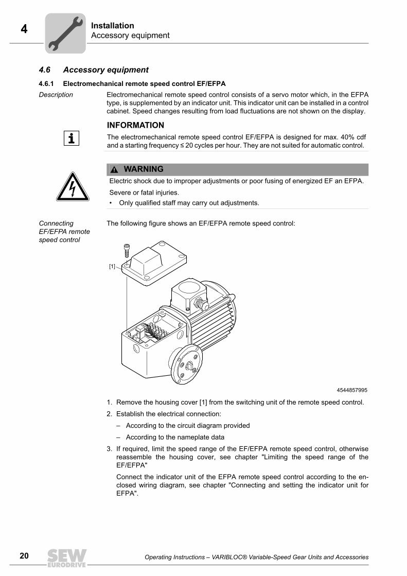
20
4 ccessory equipmentstallation
4.6 Accessory equipment4.6.1 Electromechanical remote speed control EF/EFPADescription Electromechanical remote speed control consists of a servo motor which, in the EFPA
type, is supplemented by an indicator unit. This indicator unit can be installed in a controlcabinet. Speed changes resulting from load fluctuations are not shown on the display.
Connecting EF/EFPA remote speed control
The following figure shows an EF/EFPA remote speed control:
1. Remove the housing cover [1] from the switching unit of the remote speed control.
2. Establish the electrical connection:
– According to the circuit diagram provided
– According to the nameplate data
3. If required, limit the speed range of the EF/EFPA remote speed control, otherwisereassemble the housing cover, see chapter "Limiting the speed range of theEF/EFPA"
Connect the indicator unit of the EFPA remote speed control according to the en-closed wiring diagram, see chapter "Connecting and setting the indicator unit forEFPA".
INFORMATIONThe electromechanical remote speed control EF/EFPA is designed for max. 40% cdfand a starting frequency ≤ 20 cycles per hour. They are not suited for automatic control.
WARNINGElectric shock due to improper adjustments or poor fusing of energized EF an EFPA.
Severe or fatal injuries.• Only qualified staff may carry out adjustments.
4544857995
[1]
AIn
Operating Instructions – VARIBLOC® Variable-Speed Gear Units and Accessories

4Accessory equipmentInstallation
Connecting and setting the indica-tor unit for EFPA
The following figure shows how to set the potentiometer of the EF/EFPA remote speedcontrol:
1. Set the gearmotor to the required maximum speed.
2. Remove the housing cover [1] from the switching unit of the remote speed control.
3. Adjust and fasten the potentiometer [5] of the remote speed control:
– Loosen the lower screw of the coupling [4].
– Turn the potentiometer [5] on the coupling to the right by about 15° to about 120 –180 Ω at terminals 6 and 7.
– Tighten the lower screw of the coupling [4].
4. Connect the indicator unit to the line voltage.
– Do not connect terminals 5, 6, and 7.
5. Use the "Min" potentiometer to set the display to 0%.
6. Bypass terminals 5 and 6 of the indicator unit.
7. Turn the "Mitte" potentiometer all the way to the right.
8. Use the "Max" potentiometer to set the display to 100%.
9. Remove the bridge between terminals 5 and 6.
10.Connect terminals 5 and 7 of the indicator unit to terminals 5 and 6 of the remotespeed control.
4544861323
[2][3]
[4]
[1]
[5]
Operating Instructions – VARIBLOC® Variable-Speed Gear Units and Accessories
21
22
4 ccessory equipmentstallation
11.Use the "Mitte" potentiometer to set the display according the setting range R (seefollowing table).
12.Connect the indicator unit to the remote speed control according to the enclosed wir-ing diagram.
13.Set the gearmotor to the required minimum speed.
14.Use the "Min" potentiometer to set the display according the setting range R (see fol-lowing table).
15.Set the gearmotor to the required maximum speed.
16.Use the "Max" potentiometer to set the display to 100%.
17.Set the gearmotor to the mean speed (display = 50%).
18.If the display does not show 50%:
– Readjust the display with the "Mitte" potentiometer.
– Repeat steps 13 – 16.
19.If required, limit the speed range according to the limit speed values stated under 13and 15, see chapter "Limiting the speed range for EF/EFPA" (page 23).
The following table shows the adjustment values for the "Mitte" and "Min" potentiome-ters according to the setting range R:
4544864267
Setting range R
"Mitte" potentiometer adjustment values
VU01 /VZ01
VU11 /VZ11
VU21 /VZ21
VU31 /VZ31
VU41 /VZ41
VU51 VU6
1:8 – 34% 22% 38% – – –
1:6 32% 35% 27% 28% 35% 38% –
1:4 – – – – – – 36%
"Min" potentiometer adjustment values
1:8 13%
1:6 17%
1:4 25%
6 75 SL MITTE
MIN
220V
MAX
AIn
Operating Instructions – VARIBLOC® Variable-Speed Gear Units and Accessories

4Accessory equipmentInstallation
Limiting the speed range for EF/EFPA
The trip stop cams are preset for the entire speed range of the VARIBLOC® variable-speed gearmotor. However, it may be limited as follows:
1. Set VARIBLOC® to the required minimum speed.
2. A) Lower trip stop cam [2]– Loosen the lower trip stop cam with a screw driver.
– Turn it to the left up to the trip point.
Additionally for variant with potentiometer [5]:– B) Loosen the lower screw of the coupling [4].
– C) Turn the potentiometer [5] on the coupling:
• All the way to the left
• To the right by about 15° to about 120 – 180 Ω at terminals 6 and 7.
NOTICEDamages due to mechanical stop.
Possible damage to property• Only limit the setting range via limit switches. Prevent hitting the mechanical stop.
4544866955[2]
[3]
[4]
[1]
[5]
Operating Instructions – VARIBLOC® Variable-Speed Gear Units and Accessories
23
24
4 ccessory equipmentstallation
– D) Tighten the lower screw of the coupling.
3. Fasten the lower trip stop cam [2].
4. Set VARIBLOC® to the required maximum speed.
5. Upper trip stop cam [3]– Loosen the upper trip stop cam with a screw driver.
– Turn it to the right up to the trip point.
– Fasten the upper trip stop cam.
6. Assemble the housing cover [1] according to the enclosed wiring diagram.
4544870027
[2][3]
[4]
[1]
[5]
AIn
Operating Instructions – VARIBLOC® Variable-Speed Gear Units and Accessories

4Accessory equipmentInstallation
4.6.2 HY hydraulic adjustment deviceThe following figure shows an HY hydraulic adjustment device:
The hydraulic adjustment device is a closed system. The required adjustment force isgenerated by the piston of the adjustment cylinder. It is charged with the stress (springforce) of the driven variable pulley. The system is filled free from air. The adjustmenttravel of the actuator cylinder corresponds to the one of the adjustment cylinder sinceboth piston diameters are identical.
Adjustment cylinder assembly
The actuator cylinder is preassembled. The high-pressure hose and the adjustmentcylinder must be screwed on (bending radius of the high-pressure hose ≥ 40 mm). Theadjustment cylinder can be attached to a unit wall in any position:
1. Remove the pin [2] and the handwheel [1].
2. Unscrew the hex nuts [3] and [4].
3. Fasten the adjustment cylinder [6] on the unit wall [5] with 4 M5 pan head screws(according to DIN 912).
4. Reinstall the hex head screws, the handwheel and the pin.
4544873483
[1] Handwheel [6] Adjustment cylinder[2] Pin [7] T-head bolt[3] Hex nut [8] Adjustment bolt[4] Hex nut [9] Closing plate[5] Unit wall
[2] [4] [5] [6][1] [3]
[7]
[9]
[8]≤ 10
Operating Instructions – VARIBLOC® Variable-Speed Gear Units and Accessories
25
26
4 ccessory equipmentstallation
Limiting the speed range
The limit speed values are preset for the entire speed range of the VARIBLOC® gear-motor. However, it may be limited as follows:
1. Limiting the high speed:– Set the required max speed.
– Turn the hex nut [4] to the right and lock it with the hex nut [3].
2. Limiting the low speed:– Set the required min speed.
– Remove the closing plate [9] and loosen the hammer head screw [7].
– Move the hammer head screw [7] to the end of the adjustment bolt [8].
– Tighten the hammer head screw [7].
4.6.3 GW, IG, TW, TA, FA, FD, DA and FLDifferent designs The following designs are available:
GW AC encoder, IG voltage pulse encoder
Possible areas of application are:
GW AC encoder installation
Proceed as follows to install the GW AC encoder:
1. Install the AC encoder [6] in the tacho flange [3].
– Tongue must engage in shaft groove [4]
2. Secure the AC encoder [6] with the setscrew [2].
Accesso-ries
Variant
GW = The scope of delivery for this type only includes the GW AC encoder [3]without indicator unit FL or DA.
IG = The scope of delivery for this variant only includes the IG voltage pulseencoder without FL or DA indicator unit.
TW = Right-angled tachogenerator, does not comprise any other types TA = Axial tachogenerator, does not comprise any other typesFA = This variant includes the GW AC voltage pulse encoder with analog FA
remote speed indication (scale 0%...100%).FD = This variant includes the GW AC encoder with analog FD remote speed
indication (special scale).FL = This variant includes the IG voltage pulse encoder with analog FL
remote speed indication.DA = This variant includes the IG voltage pulse encoder with digital DA
remote speed indication.
• GW AC encoder: at VU 01 – 51 / VZ 01 – 41• IG voltage pulse encoder: at VU 6 and at VU/VZ 01 – 41 with BMG brake
AIn
Operating Instructions – VARIBLOC® Variable-Speed Gear Units and Accessories

4Accessory equipmentInstallation
The following figure illustrates the installation of the GW AC encoder, the TW right-angled tachogenerator and the TA axial tachogenerator:
IG voltage pulse encoder installa-tion
The following figure illustrates installation of the IG voltage pulse encoder:
1. Place the screw head [1] in front of the bore for the voltage pulse encoder [2].
2. Screw the voltage pulse encoder [2] in the corresponding thread of the gear unithousing until it contacts the screw head [1].
3. Turn back the voltage pulse encoder [2] by 2 revolutions (distance = 2 mm).
4. Secure the voltage pulse encoder [2] with a lock nut.
5. If there is no display, adjust the input sensitivity:
– Increase or reduce the distance of the voltage pulse encoder and the screw head.
4544965899
[3][2]
[4]
[1]
[6]
[5]
4544968843
[1] [2]
2 mm
Operating Instructions – VARIBLOC® Variable-Speed Gear Units and Accessories
27
28
4 ccessory equipmentstallation
TW right-angled tachometer, TA axial tachometer
The tachometers TW [1] and TA [5] can be installed as an alternative to the AC encoder,see the figure above.
Installing the analog FA, FD remote speed indicator
The analog remote speed indicators FA (with scale 0 – 100%) or FD (scale according tocustomer demand) are connected to the GW AC encoder.
1. Connect the device to the AC encoder according to the terminal designations.
2. Accelerate the drive to the maximum speed.
3. Use the potentiometer on the back of the unit to adjust the unit to 100% pointerdeflection.
Connecting and adjusting the analog FL remote speed indicator
The contactless analog FL remote speed indicator is connected to the IG voltage pulseencoder on the variable-speed gear unit.
1. Wire the unit.
2. Accelerate the drive to the maximum speed.
3. Adjust the device to 100% display via the setting screws for rough setting [1] or finetuning [2] on the back of the indicator unit.
4. Ensure a flawless ground connection at terminal M.
Technical data The following table lists the data of the analog FL remote speed indicator:
4545491083[1] Rough setting[2] Fine tuning
IG1
23
230 V M
[1]
[2]
GBS S
Description
Display unit Analog (scale 0 – 100%)
Line connection 230 V, 40 – 60 Hz
Encoder connection With two-core cable, shielded
AIn
Operating Instructions – VARIBLOC® Variable-Speed Gear Units and Accessories

4Accessory equipmentInstallation
Connecting and adjusting the analog FL remote speed indicator
The contactless, digital DA remote speed indicator is connected to the GW AC encoderor the IG voltage pulse encoder:
1. Wire the unit as shown in the following figure:
2. Ensure a flawless ground connection at terminal 1.
3. Adjust the measuring time according to the following figure and chapter "Calculationexamples DA":
– Calculated with a formula
– Data according to table in section "Setting data of digital DA remote speed indi-cation" (page 30)
4. Set the input sensitivity, see figure above.
– Turn the input sensitivity potentiometer to the right until the pulse monitoring lightjust lights up.
4544971659[1] Auxiliary voltage[2] Jumper 8 – 9[3] Jumpers 7 – 9 and 8 – 10
4544974987[1] Time base in s[2] Pulse multiplier:[3] Pulse monitoring[4] Decimal point setting[5] Input sensitivity
IG
2
1 1 2 21
3
1
GW
[1]
1 2
115 V[3]
230 V[2]
3 4 5 6 7 8 9 10
1 0.1 x10 x10.01 0.001
[1] [2]
[3]
[4]
[5]
Operating Instructions – VARIBLOC® Variable-Speed Gear Units and Accessories
29
30
4 ccessory equipmentstallation
Technical data The following table lists the technical data of the digital DA remote speed indicator:
Adjusting the digital DA remote speed indicator.
The following table lists the adjustment data of the digital DA remote speed indicator:
Reference speed The following table lists the reference speed of the digital DA remote speed indicator:
Description
Display unit Digital
Line connection 230/115 V; 50 – 60 Hz
Power consumption About 4.2 VA
Encoder connection With two-core cable, shielded
Indicating accuracy ±1 of last digit
Measuring interval (time base: quartz)
Adjustment in increments of 0,001 s in the range of 0,010 s to 9,999 s after removing the front panelRecommended measuring interval: 0.5 – 2 s
Pulse multiplier: Adjustment in increments in the range from 1 - 99 after removing the front panel
Decimal point setting Via DIP switch after removing the front panel
Calculation of measuring interval Measuring interval =
A = four-digit display (at maximum speed), without decimal point indicationn = speed (see following table)k = pulse multiplier ≥ 1z = pulses / revolution (see following table)f = calculation factor (at 50 Hz = 1, at 60 Hz = 1.2)
60 ×× × ×
A
n k z f
Gear unit type and size
Pulses/ revolution
VARIBLOC® reference speed in rpm
R = 1:6 / 6:1 R = 1:8 / 8:1
4-pole 6-pole 8-pole1) 4-pole 6-pole 8-pole1)
VU / VZ 01
4
3100 2045 1550 – – –
VU / VZ 11 3250 2160 1615 3905 2530 1870
VU / VZ 21 3100 2050 1530 4004 2631 1916
VU / VZ 31 3100 2050 1540 4090 2688 2002
VU / VZ 41 3053 2035 1505 – – –
VU 51 3106 2056 1526 – – –
R = 1:4 (1:3) / 4:1 (3:1) – – –
VU 6 (D 200)6
2528 1668 1247 – – –
VU 6 (D 225) 2087 – – – – –
1) Only for DT/DV motors.
AIn
Operating Instructions – VARIBLOC® Variable-Speed Gear Units and Accessories

4Accessory equipmentInstallation
Calculation examples DA
Example 1 Example 2
Drive R107 R77 VU21DA DRE100M4 R107 R77 VU21DA DRE100M4
Data Output speed na = 1.0 – 6.4 Output speed na = 1.0 – 6.4
Number of pulses z = 4 Number of pulses z = 4
Max. speed of the variable-speed gear unit (see table above)
n = 3100 rpm Max. speed of the vari-able-speed gear unit (see table above)
n = 3100 rpm
Required indication Output speed A = 1.000 – 6.400 rpm Belt velocity A = 0.114 – 0.72 m / min
Measuring interval =
Recommended measuring interval
0.5 - 2 s (max. 9.999 s)
Calculation with new pulse multiplier
k = 25Measuring interval =
k = 4Measuring interval =
Unit setting Measuring interval [1] [2] [3] [9] Measuring interval [0] [8] [7] [1]
Pulse multiplier [2] [5] Pulse multiplier [0] [4]
Decimal point setting [1] Decimal point setting [1]
60 ×× × ×
A
n k z f
60 64003100 1 4 1
30 97×× × ×
= . s60 720
3100 1 4 13 484×
× × ×= . s
60 64003100 25 4 1
1 239×× × ×
= . s
60 7203100 4 4 1
0 871×× × ×
= . s
Operating Instructions – VARIBLOC® Variable-Speed Gear Units and Accessories
31
32
5 tartup
5 Startup
• Secure the key for test mode without output elements.
• The most important technical data is provided on the nameplate. Additional datarelevant for operation is available in drawings and the order confirmation.
• Ensure that all retaining screws are tight after the gear unit has been installed.
• Make sure that the orientation has not changed after tightening the mountingelements.
• Prior to startup, ensure that rotating shafts as well as couplings are equipped withsuitable protective covers.
• It is essential that there is no open fire or risk of sparks when working on the gear unit.
• Protect the gear unit from falling objects.
• Remove transport fixtures prior to startup.
• Adhere to the safety notes in the individual chapters.
• Check the degree of protection.
• Check that there is sufficient clearance around the motor to provide for adequatecooling, and that the motor does not suck in warm air from other devices.
NOTICEDamages to the adjustment device and the wide V-belt due to adjustments to the vari-able-speed gear units at standstill.
Possible damage to property• Never adjust variable-speed gear units at standstill.
INFORMATIONBefore startup, check the bolted connections at the customer flange (page 16).
S
00
I
Operating Instructions – VARIBLOC® Variable-Speed Gear Units and Accessories

5Speed adjustment via handwheeStartup
5.1 Speed adjustment via handwheelTurning the handwheel changes the speed range as follows:
• CCW rotation decreases the drive speed
• CW rotation increases the drive speed
The following figure illustrates the directions:
The mechanical limitation of the setting range is achieved via a retaining ring for the min-imum output speed na1 and by locking the variable pulleys for the maximum outputspeed na2.
With VARIBLOC® variable-speed gear units, there is a digressive relation between thehandwheel rotations at the adjustment spindle and the output speed.
Decreasing speed Increasing speed
VARIBLOC® type Required handwheel rotations
Setting range in rela-tion to the maximum output speed in %
Setting range
VU/VZ 01 6.5 19 – 102 R 1:5
VU/VZ 11 9 16.5 – 103 R 1:6
VU/VZ 21 12 16 – 108 R 1:6
VU/VZ 31 14.5 16 – 104 R 1:6
VU/VZ 41 14.5 19 – 102 R 1:6
VU 51 17.5 16 – 100 R 1:6
VU 6 18.25 20 – 100 R 1:4
VU/VZ 11 10 14 – 111 R 1:8
VU/VZ 21 13 12.5 – 103 R 1:8
VU/VZ 31 16.5 12 – 105 R 1:8
VU 6 17 32 – 104 R 1:3
Operating Instructions – VARIBLOC® Variable-Speed Gear Units and Accessories
l00
I
33

34
5 peed adjustment via handwheeltartup
The following figure shows an example of an adjustment curve for VARIBLOC® sizeVU6 (R 1:3):
4760792203
[A] Handwheel rotations[B] % of the final speed
16
14
18
12
8
10
6
4
2
00 30 40 60 7010 20 50 80 10090 110
[A]
[B]
SS
00
I
Operating Instructions – VARIBLOC® Variable-Speed Gear Units and Accessories
6Preliminary work regarding gear unit inspection/maintenanceInspection/Maintenance
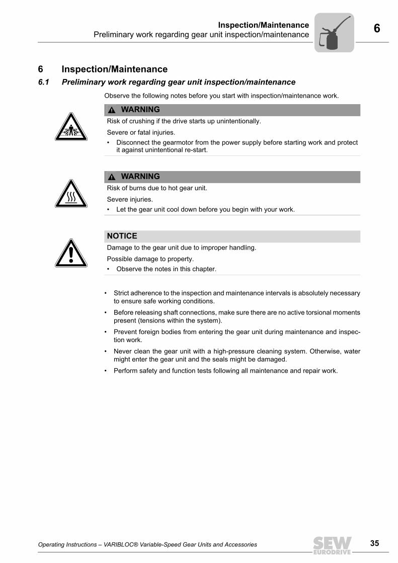
6 Inspection/Maintenance6.1 Preliminary work regarding gear unit inspection/maintenance
Observe the following notes before you start with inspection/maintenance work.
• Strict adherence to the inspection and maintenance intervals is absolutely necessaryto ensure safe working conditions.
• Before releasing shaft connections, make sure there are no active torsional momentspresent (tensions within the system).
• Prevent foreign bodies from entering the gear unit during maintenance and inspec-tion work.
• Never clean the gear unit with a high-pressure cleaning system. Otherwise, watermight enter the gear unit and the seals might be damaged.
• Perform safety and function tests following all maintenance and repair work.
WARNINGRisk of crushing if the drive starts up unintentionally.
Severe or fatal injuries.• Disconnect the gearmotor from the power supply before starting work and protect
it against unintentional re-start.
WARNINGRisk of burns due to hot gear unit.
Severe injuries.• Let the gear unit cool down before you begin with your work.
NOTICEDamage to the gear unit due to improper handling.
Possible damage to property.• Observe the notes in this chapter.
Operating Instructions – VARIBLOC® Variable-Speed Gear Units and Accessories
35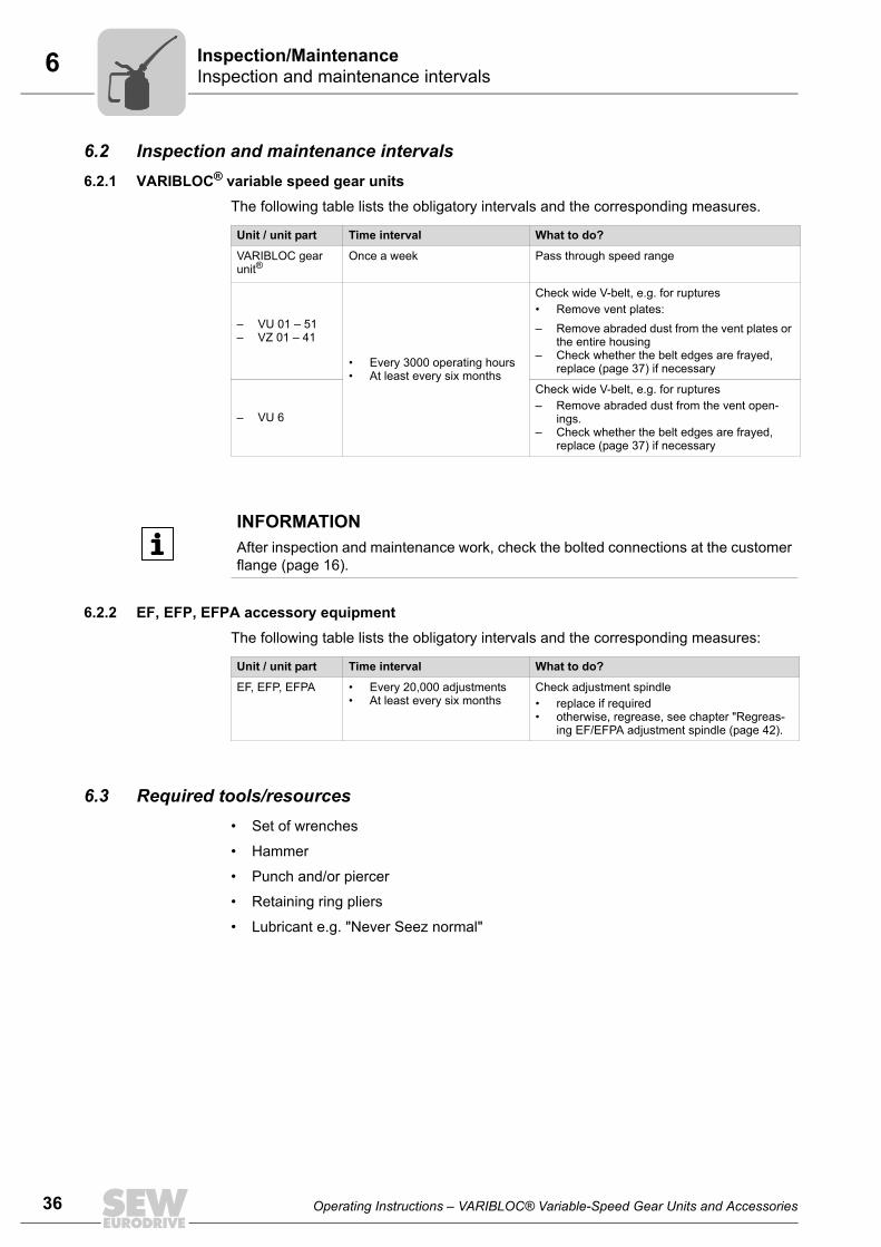
36
6 spection and maintenance intervalsspection/Maintenance
6.2 Inspection and maintenance intervals6.2.1 VARIBLOC® variable speed gear units
The following table lists the obligatory intervals and the corresponding measures.
6.2.2 EF, EFP, EFPA accessory equipmentThe following table lists the obligatory intervals and the corresponding measures:
6.3 Required tools/resources• Set of wrenches
• Hammer
• Punch and/or piercer
• Retaining ring pliers
• Lubricant e.g. "Never Seez normal"
Unit / unit part Time interval What to do?
VARIBLOC gear unit®
Once a week Pass through speed range
• Every 3000 operating hours• At least every six months
Check wide V-belt, e.g. for ruptures• Remove vent plates:– Remove abraded dust from the vent plates or
the entire housing– Check whether the belt edges are frayed,
replace (page 37) if necessary
– VU 01 – 51– VZ 01 – 41
– VU 6
Check wide V-belt, e.g. for ruptures– Remove abraded dust from the vent open-
ings.– Check whether the belt edges are frayed,
replace (page 37) if necessary
INFORMATIONAfter inspection and maintenance work, check the bolted connections at the customerflange (page 16).
Unit / unit part Time interval What to do?
EF, EFP, EFPA • Every 20,000 adjustments• At least every six months
Check adjustment spindle• replace if required• otherwise, regrease, see chapter "Regreas-
ing EF/EFPA adjustment spindle (page 42).
InIn
Operating Instructions – VARIBLOC® Variable-Speed Gear Units and Accessories

6Replacing the wide V-beltInspection/Maintenance
6.4 Replacing the wide V-belt
6.4.1 Replacing the wide V-belt for VU 01 – 51 and VZ 01 – 41The following figure illustrates the structure of a variable-speed gear unit:
1. Set the gearmotor to the highest speed and lock it.
2. DANGER Unintended start-up of the machine.
Severe or fatal injuries.
– Deenergize the gearmotor
– Block output side
3. Remove the two vent plates [1].
4. Remove the bearing cover [2] and the adjusting device [3].
5. Loosen the housing screws and separate the casing halves A and B
6. Secure the driven, spring-loaded variable pulley GV with the wooden wedge [8].
INFORMATIONUse only genuine spare parts in accordance with the valid parts list.
4548261259
[1] Vent plate [7] Wide V-belt[2] Bearing cover [8] Wooden wedge[3] Adjusting device [A] Casing half A[4] Adjusting sleeve [B] Casing half B[5] Retaining ring [TV] Driving variable pulley (a + b)[6] Ball bearing [GV] Driven variable pulley
[1]
[2]
[3]
[A]
[4]
[5]
[6]
[TVa]
[TVb]
[7]
[B]
[GV]
[8]
Operating Instructions – VARIBLOC® Variable-Speed Gear Units and Accessories
37
38
6 eplacing the wide V-beltspection/Maintenance
DANGER Risk of crushing as the spring load might pull the disk halves backtogether.
Possible injury.
– Secure driven spring-loaded variable pulley GV with the wooden wedge [8].
7. Disassemble:
– Adjusting sleeve [4] (only for variant with front adjustment)
– Retaining ring [5]
– Driving variable pulley halves TVa
8. Remove the existing wide V-belt [7] and insert the new wide V-belt.
9. Assemble:
– Driving variable pulley halves TVa
– Ball bearing [6]
– Retaining ring [5]
– Adjustment sleeve [4]
10.Remove the wooden wedge.
11.Install the casing halves A and B.
12.Assemble the adjustment device and the bearing cover.
13.Fasten the mounting vent plates.
14.Fix the wide V-belt via the adjustment device [3] by turning the adjustment spindle inCW direction until you feel a resistance.
15.Remove the blocking from the input side.
DANGER Unintended start-up of the machine.
Severe or fatal injuries.
– Ensure that the gearmotor is deenergized.
16.Switch on the gearmotor.
17.Slowly move through the speed range.
– Drive runs smoothly and evenly;
If the drive does not run smoothly and evenly, check the correct installation of thedrive.
RIn
Operating Instructions – VARIBLOC® Variable-Speed Gear Units and Accessories

6Replacing the wide V-beltInspection/Maintenance
6.4.2 Replacing the wide V-belt for VU 6The following figure illustrates the structure of a variable-speed gear unit:
1. Set the gearmotor to the highest speed and lock it.
2. DANGER Unintended start-up of the machine.
Severe or fatal injuries.
– Deenergize the gearmotor
– Block output side
3. Open the driving variable pulley TV all the way by turning the adjustment device [4]counterclockwise as far as it will go.
4. For variant with front adjustment:– Remove sheet metal cover [1], retaining ring [2] and supporting ring [3].
– Unscrew the adjustment device [4] all the way by turning it clockwise.
– Loosen the screws of the cover [5] and remove it. Remove the adjustment device.
For all other variants:– Disassemble the entire adjustment device [4].
5. Loosen the housing screws and remove the casing half A.
4548266635
[5][3]
[2]
[3][4]
[A]
[6]
[TVa]
[7]
[TVb][B]
[GV]
[8]
[1][2]
[1] Sheet metal cover [7] Wide V-belt[2] Retaining ring [8] Wooden wedge[3] Supporting ring [TV] Driving variable pulley (a + b)[4] Adjusting device [GV] Driven variable pulley[5] Cover [A] Casing half A[6] Ball bearing [B] Casing half B
Operating Instructions – VARIBLOC® Variable-Speed Gear Units and Accessories
39
40
6 eplacing the wide V-beltspection/Maintenance
6. Secure the driven, spring-loaded variable pulley GV with the wooden wedge [8].
DANGER Risk of crushing as the spring load might pull the disk halves backtogether.
Possible injury.
– Secure driven spring-loaded variable pulley GV with the wooden wedge [8].
7. On the driving variable pulley [TV]:
– Remove the supporting ring [3] and the retaining ring [2].
– Remove the ball bearing [6] and the variable pulley half [TVa].
8. Remove the existing wide V-belt [7] and insert the new wide V-belt.
9. Assemble on driving variable pulley:
– Variable pulley half [TVa]
– Ball bearing [6]
– Retaining ring [2]
– Supporting ring [3]
10.Remove the wooden wedge [8].
11.Install the casing halves A and B.
12.Assemble the adjustment device [4] in the opposite order as under step 4.
13.Tension the wide V-belt via the adjustment device [4] by turning the adjustment spin-dle in CW direction until you feel a resistance.
14.Remove the blocking on the input side.
DANGER Unintended start-up of the machine.
Severe or fatal injuries.
– Ensure that the gearmotor is de-energized.
15.Switch on the gearmotor.
16.Slowly move through the speed range.
– Drive runs smoothly and evenly;
If the drive does not run smoothly and evenly, check the correct installation of thedrive.
RIn
Operating Instructions – VARIBLOC® Variable-Speed Gear Units and Accessories

6Limiting the speed range for NV, H, HS designInspection/Maintenance
6.5 Limiting the speed range for NV, H, HS designThe following figure shows the adjustment device with and without position indicator:
The limit speeds nmin and nmax are factory set. You may have to readjust the speedrange due to the wear of the belt or after you have replaced the wide V-belt.
1. Remove the closing plate [1] from the adjustment device.
2. Set the required maximum speed as described below:
– Loosen the hammer head screw [2].
– Increase the speed.
– Lock the hammer head screw in this position.
3. Set the required minimum speed as described below:
– Loosen the hammer head screw [3].
– Decrease the speed.
– Lock the hammer head screw in this position.
4549121419
[1]
[3]
[2]
H HS
Operating Instructions – VARIBLOC® Variable-Speed Gear Units and Accessories
41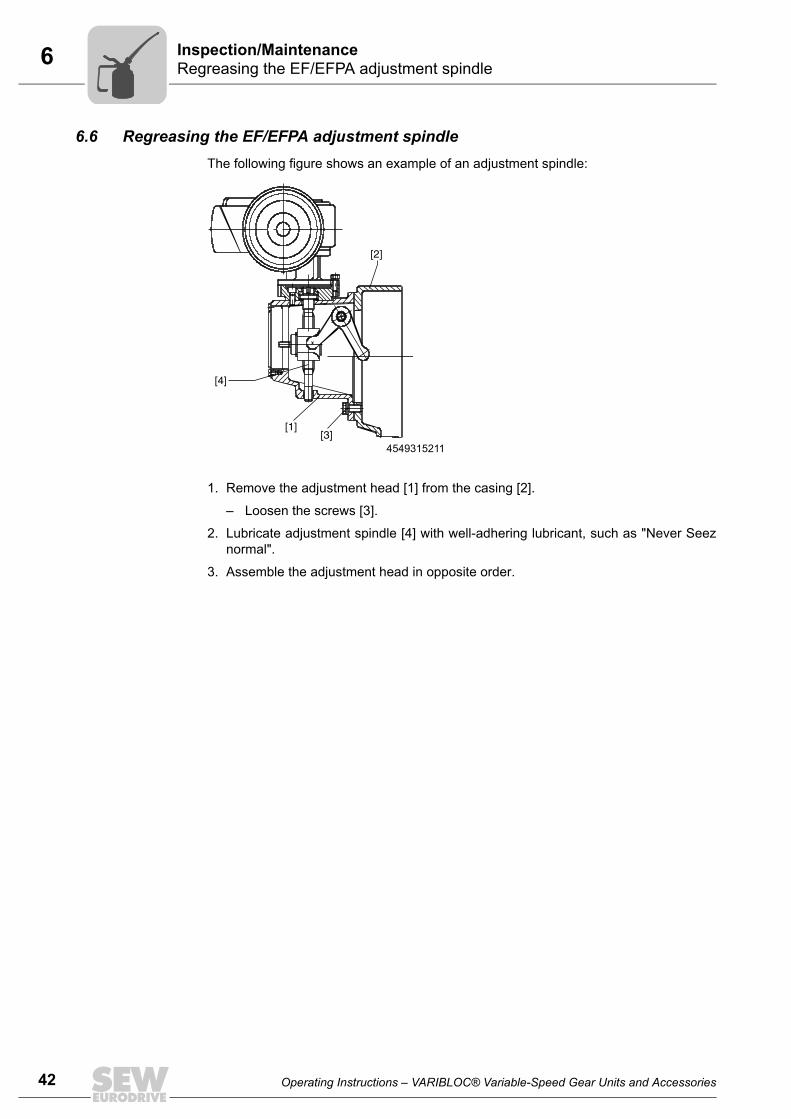
42
6 egreasing the EF/EFPA adjustment spindlespection/Maintenance
6.6 Regreasing the EF/EFPA adjustment spindleThe following figure shows an example of an adjustment spindle:
1. Remove the adjustment head [1] from the casing [2].
– Loosen the screws [3].
2. Lubricate adjustment spindle [4] with well-adhering lubricant, such as "Never Seeznormal".
3. Assemble the adjustment head in opposite order.
4549315211
[2]
[4]
[1][3]
RIn
Operating Instructions – VARIBLOC® Variable-Speed Gear Units and Accessories

7Extended storageTechnical Data
7 Technical Data7.1 Extended storage
For long-term storage, option ../B (in corrosion protection design) is used.
This requires the following additional measures:
Once you have performed a test run with the gear unit to be stored, disassemble thewide V-belt and enclose it with the drive in a stable box. The wide V-belt should have anearly elliptic shape.
The storage environment must be cold (temperature range 0° - 20° C), dry and free fromdust.
The following points must be avoided during extended storage:
• direct exposure to heat
• sudden change in temperature
• draft
• exposure to ultraviolet radiation
• electric devices and plants in direct vicinity (accumulation of ozone)
• mechanical load
• impacts due to oils, acids and solvent vapors
The wide V-belt can be stored about 2 years if the above conditions are observed.
INFORMATIONFor storage periods longer than 9 months, SEW-EURODRIVE recommends the "Ex-tended storage" type. Gear units in this design are designated with a correspondinglabel.
Operating Instructions – VARIBLOC® Variable-Speed Gear Units and Accessories
Pi
fkVA
Hz
n
43

44
8 ARIBLOC® variable-speed gear unitalfunctions
8 Malfunctions8.1 VARIBLOC® variable-speed gear unit
8.2 Accessory equipment8.2.1 Electromechanical remote speed control EF, EFPA
Malfunction Possible cause Solution
Drive slipping Wide V-belt is worn. Replace wide V-belt. see chapter "Replacing wide V-belt" (page 37).
Wide V-belt or face of adjustment disk is contaminated.
Clean contaminated part:• Clean wide V-belt with dry
cloth or paper• Clean adjustment disk with
solvent or similar product
Load is too high. Check picked off power and reduce to catalog values.Drive warms up excessively Load is too high.
Drive is too loud Wide V-belt is damaged1)
1) Damage can occur after brief blocking or impulsive load of the drive, for example.
• Eliminate the cause• Replace wide V-belt, see
chapter "Replacing wide V-belt" (page 37)
Speed variations occur Wide V-belt is damaged1) Replace wide V-belt, see chapter "Replacing wide V-belt" (page 37)
Malfunction Possible cause Solution
Impossible to change speed Device is not connected properly. Connect device correctly accord-ing to wiring diagram.
Speed range is not reached. Limit switches of the adjustment motor trip too early.
Set cams for limit switches cor-rectly. See chapter "Limiting the speed range for EF, EFPA" (page 23).
No display • Indicator unit is not connected properly.
• Voltage supply is missing or interrupted.
Connect indicator unit correctly according to wiring diagram.
Incorrect display Display not adjusted properly. Set display on the back of the device. See chapter "Connecting and setting the indicator unit for EFPA" (page 21).
VM
Operating Instructions – VARIBLOC® Variable-Speed Gear Units and Accessories

8Customer serviceMalfunctions
8.2.2 Contactless FL and DA remote speed indication, IG voltage pulse encoder
8.2.3 HY hydraulic adjustment device
8.3 Customer servicePlease have the following information available if you require customer serviceassistance:• Nameplate data (complete)
• Type and extent of the problem
• Time the problem occurred and any accompanying circumstances
• Assumed cause
A digital photograph if possible
8.4 DisposalDispose gear units in accordance with the regulations in force regarding respective ma-terials:
• Steel scrap
– Housing parts
– Gears
– Shafts
– Roller bearing
• Parts of the worm gears are made of non-ferrous metals. Dispose of the worm gearsas appropriate.
• Collect waste oil and dispose of it according to the regulations in force.
Malfunction Possible cause Solution
No display and/or no signal Input sensitivity (distance voltage pulse encoder/screw head) too large or too little.
Correct input sensitivity:• Reduce/increase distance
between IG voltage pulse encoder and screw head. See chapter "Installing IG voltage pulse encoder" (page 27).
• Device is not connected prop-erly.
• Voltage supply is missing or interrupted.
Connect device correctly accord-ing to wiring diagram.
Malfunction Possible cause Solution
Little oil loss Small leakage Repair the leakage, refill oil (screw on adjustment cylinder)
Operating Instructions – VARIBLOC® Variable-Speed Gear Units and Accessories
45
46
9 ddress List
9 Address List
Germany
HeadquartersProductionSales
Bruchsal SEW-EURODRIVE GmbH & Co KGErnst-Blickle-Straße 42 D-76646 BruchsalP.O. BoxPostfach 3023 • D-76642 Bruchsal
Tel. +49 7251 75-0Fax +49 7251 75-1970http://[email protected]
Production / Indus-trial Gears
Bruchsal SEW-EURODRIVE GmbH & Co KGChristian-Pähr-Str.10D-76646 Bruchsal
Tel. +49 7251 75-0Fax +49 7251 75-2970
Service Compe-tence Center
Central SEW-EURODRIVE GmbH & Co KGErnst-Blickle-Straße 1 D-76676 Graben-Neudorf
Tel. +49 7251 75-1710Fax +49 7251 [email protected]
North SEW-EURODRIVE GmbH & Co KGAlte Ricklinger Straße 40-42 D-30823 Garbsen (near Hannover)
Tel. +49 5137 8798-30Fax +49 5137 [email protected]
East SEW-EURODRIVE GmbH & Co KGDänkritzer Weg 1D-08393 Meerane (near Zwickau)
Tel. +49 3764 7606-0Fax +49 3764 [email protected]
South SEW-EURODRIVE GmbH & Co KGDomagkstraße 5D-85551 Kirchheim (near München)
Tel. +49 89 909552-10Fax +49 89 [email protected]
West SEW-EURODRIVE GmbH & Co KGSiemensstraße 1D-40764 Langenfeld (near Düsseldorf)
Tel. +49 2173 8507-30Fax +49 2173 [email protected]
Electronics SEW-EURODRIVE GmbH & Co KGErnst-Blickle-Straße 42 D-76646 Bruchsal
Tel. +49 7251 75-1780Fax +49 7251 [email protected]
Drive Service Hotline / 24 Hour Service +49 180 5 SEWHELP+49 180 5 739435714 euro cents/min on the German land-line network. Max 42 euro cents/min from a German mobile network. Prices for mobile and international calls may differ.
Additional addresses for service in Germany provided on request!
France
ProductionSalesService
Haguenau SEW-USOCOME 48-54 route de Soufflenheim B. P. 20185F-67506 Haguenau Cedex
Tel. +33 3 88 73 67 00 Fax +33 3 88 73 66 00http://[email protected]
Production Forbach SEW-USOCOME Zone industrielle Technopôle Forbach SudB. P. 30269F-57604 Forbach Cedex
Tel. +33 3 87 29 38 00
AssemblySalesService
Bordeaux SEW-USOCOME Parc d'activités de Magellan62 avenue de Magellan - B. P. 182F-33607 Pessac Cedex
Tel. +33 5 57 26 39 00Fax +33 5 57 26 39 09
Lyon SEW-USOCOME Parc d'affaires RooseveltRue Jacques TatiF-69120 Vaulx en Velin
Tel. +33 4 72 15 37 00Fax +33 4 72 15 37 15
A
Operating Instructions – VARIBLOC® Variable-Speed Gear Units and Accessories

9Address List
Nantes SEW-USOCOME Parc d’activités de la forêt4 rue des FontenellesF-44140 Le Bignon
Tel. +33 2 40 78 42 00Fax +33 2 40 78 42 20
Paris SEW-USOCOME Zone industrielle 2 rue Denis Papin F-77390 Verneuil I'Etang
Tel. +33 1 64 42 40 80Fax +33 1 64 42 40 88
Additional addresses for service in France provided on request!
Algeria
Sales Algiers REDUCOM Sarl 16, rue des Frères ZaghnouneBellevue16200 El Harrach Alger
Tel. +213 21 8214-91Fax +213 21 [email protected]://www.reducom-dz.com
Argentina
AssemblySales
Buenos Aires SEW EURODRIVE ARGENTINA S.A.Centro Industrial Garin, Lote 35Ruta Panamericana Km 37,51619 Garin
Tel. +54 3327 4572-84Fax +54 3327 [email protected]://www.sew-eurodrive.com.ar
Australia
AssemblySalesService
Melbourne SEW-EURODRIVE PTY. LTD.27 Beverage DriveTullamarine, Victoria 3043
Tel. +61 3 9933-1000Fax +61 3 9933-1003http://[email protected]
Sydney SEW-EURODRIVE PTY. LTD.9, Sleigh Place, Wetherill Park New South Wales, 2164
Tel. +61 2 9725-9900Fax +61 2 [email protected]
Austria
AssemblySalesService
Wien SEW-EURODRIVE Ges.m.b.H. Richard-Strauss-Strasse 24A-1230 Wien
Tel. +43 1 617 55 00-0Fax +43 1 617 55 00-30http://[email protected]
Belarus
Sales Minsk SEW-EURODRIVE BYRybalkoStr. 26BY-220033 Minsk
Tel.+375 17 298 47 56 / 298 47 58Fax +375 17 298 47 54http://[email protected]
Belgium
AssemblySalesService
Brussels SEW-EURODRIVE n.v./s.a.Researchpark Haasrode 1060Evenementenlaan 7BE-3001 Leuven
Tel. +32 16 386-311Fax +32 16 386-336http://[email protected]
Service Compe-tence Center
Industrial Gears SEW-EURODRIVE n.v./s.a.Rue de Parc Industriel, 31BE-6900 Marche-en-Famenne
Tel. +32 84 219-878Fax +32 84 219-879http://[email protected]
Brazil
ProductionSalesService
São Paulo SEW-EURODRIVE Brasil Ltda.Avenida Amâncio Gaiolli, 152 - Rodovia Presi-dente Dutra Km 208Guarulhos - 07251-250 - SPSAT - SEW ATENDE - 0800 7700496
Tel. +55 11 2489-9133Fax +55 11 2480-3328http://[email protected]
France
Operating Instructions – VARIBLOC® Variable-Speed Gear Units and Accessories
47
48
9 ddress List
AssemblySalesService
Rio Claro SEW-EURODRIVE Brasil Ltda.Rodovia Washington Luiz, Km 172Condomínio Industrial ConparkCaixa Postal: 32713501-600 – Rio Claro / SP
Tel. +55 19 3522-3100Fax +55 19 [email protected]
Joinville SEW-EURODRIVE Brasil Ltda.Rua Dona Francisca, 12.346 – Pirabeiraba89239-270 – Joinville / SC
Tel. +55 47 3027-6886Fax +55 47 [email protected]
Indaiatuba SEW-EURODRIVE Brasil Ltda.Estrada Municipal Jose Rubim, 205Rodovia Santos Dumont Km 4913347-510 - Indaiatuba / SP
Tel. +55 19 [email protected]
Bulgaria
Sales Sofia BEVER-DRIVE GmbHBogdanovetz Str.1BG-1606 Sofia
Tel. +359 2 9151160Fax +359 2 [email protected]
Cameroon
Sales Douala Electro-ServicesRue Drouot AkwaB.P. 2024Douala
Tel. +237 33 431137Fax +237 33 [email protected]
Canada
AssemblySalesService
Toronto SEW-EURODRIVE CO. OF CANADA LTD. 210 Walker Drive Bramalea, ON L6T 3W1
Tel. +1 905 791-1553Fax +1 905 791-2999http://[email protected]
Vancouver SEW-EURODRIVE CO. OF CANADA LTD.Tilbury Industrial Park7188 Honeyman Street Delta, BC V4G 1G1
Tel. +1 604 946-5535Fax +1 604 [email protected]
Montreal SEW-EURODRIVE CO. OF CANADA LTD.2555 Rue Leger Lasalle, PQ H8N 2V9
Tel. +1 514 367-1124Fax +1 514 [email protected]
Additional addresses for service in Canada provided on request!
Chile
AssemblySalesService
Santiago SEW-EURODRIVE CHILE LTDA.Las Encinas 1295Parque Industrial Valle GrandeLAMPARCH-Santiago de ChileP.O. BoxCasilla 23 Correo Quilicura - Santiago - Chile
Tel. +56 2 75770-00Fax +56 2 75770-01http://[email protected]
China
ProductionAssemblySalesService
Tianjin SEW-EURODRIVE (Tianjin) Co., Ltd.No. 46, 7th Avenue, TEDATianjin 300457
Tel. +86 22 25322612Fax +86 22 [email protected]://www.sew-eurodrive.cn
AssemblySalesService
Suzhou SEW-EURODRIVE (Suzhou) Co., Ltd.333, Suhong Middle RoadSuzhou Industrial ParkJiangsu Province, 215021
Tel. +86 512 62581781Fax +86 512 [email protected]
Brazil
A
Operating Instructions – VARIBLOC® Variable-Speed Gear Units and Accessories

9Address List
Guangzhou SEW-EURODRIVE (Guangzhou) Co., Ltd.No. 9, JunDa RoadEast Section of GETDDGuangzhou 510530
Tel. +86 20 82267890Fax +86 20 [email protected]
Shenyang SEW-EURODRIVE (Shenyang) Co., Ltd.10A-2, 6th RoadShenyang Economic Technological Develop-ment AreaShenyang, 110141
Tel. +86 24 25382538Fax +86 24 [email protected]
Wuhan SEW-EURODRIVE (Wuhan) Co., Ltd.10A-2, 6th RoadNo. 59, the 4th Quanli Road, WEDA430056 Wuhan
Tel. +86 27 84478388Fax +86 27 [email protected]
Xi'An SEW-EURODRIVE (Xi'An) Co., Ltd.No. 12 Jinye 2nd RoadXi'An High-Technology Industrial Development ZoneXi'An 710065
Tel. +86 29 68686262Fax +86 29 [email protected]
Additional addresses for service in China provided on request!
Colombia
AssemblySalesService
Bogotá SEW-EURODRIVE COLOMBIA LTDA. Calle 22 No. 132-60Bodega 6, Manzana BSantafé de Bogotá
Tel. +57 1 54750-50Fax +57 1 54750-44http://[email protected]
Croatia
SalesService
Zagreb KOMPEKS d. o. o.Zeleni dol 10HR 10 000 Zagreb
Tel. +385 1 4613-158Fax +385 1 [email protected]
Czech Republic
SalesAssemblyService
Prague SEW-EURODRIVE CZ s.r.o.Floriánova 2459253 01 Hostivice
Tel. +420 255 709 601Fax +420 235 350 613http://[email protected]
SEW-EURODRIVE CZ s.r.o.Lužná 59116000 Praha 6 - Vokovice
Drive Service Hotline / 24 Hour Service
HOT-LINE +420 800 739 739 (800 SEW SEW) Servis:Tel. +420 255 709 632Fax +420 235 358 [email protected]
Denmark
AssemblySalesService
Copenhagen SEW-EURODRIVEA/SGeminivej 28-30DK-2670 Greve
Tel. +45 43 9585-00Fax +45 43 9585-09http://[email protected]
Egypt
SalesService
Cairo Copam Egypt for Engineering & Agencies33 EI Hegaz ST, Heliopolis, Cairo
Tel. +20 2 22566-299 +1 23143088Fax +20 2 22594-757http://www.copam-egypt.com/ [email protected]
China
Operating Instructions – VARIBLOC® Variable-Speed Gear Units and Accessories
49
50
9 ddress List
Estonia
Sales Tallin ALAS-KUUL ASReti tee 4EE-75301 Peetri küla, Rae vald, Harjumaa
Tel. +372 6593230Fax +372 [email protected]
Finland
AssemblySalesService
Lahti SEW-EURODRIVE OYVesimäentie 4FIN-15860 Hollola 2
Tel. +358 201 589-300Fax +358 3 780-6211http://[email protected]
ProductionAssembly
Karkkila SEW Industrial Gears OyValurinkatu 6, PL 8FI-03600 Karkkila, 03601 Karkkila
Tel. +358 201 589-300Fax +358 201 [email protected]://www.sew-eurodrive.fi
Gabon
Sales Libreville ESG Electro Services GabunFeu Rouge Lalala1889 LibrevilleGabun
Tel. +241 741059Fax +241 [email protected]
Great Britain
AssemblySalesService
Normanton SEW-EURODRIVE Ltd.Beckbridge Industrial Estate NormantonWest Yorkshire WF6 1QR
Tel. +44 1924 893-855Fax +44 1924 893-702http://[email protected]
Drive Service Hotline / 24 Hour Service Tel. 01924 896911
Greece
Sales Athens Christ. Boznos & Son S.A.12, K. Mavromichali StreetP.O. Box 80136GR-18545 Piraeus
Tel. +30 2 1042 251-34 Fax +30 2 1042 251-59http://[email protected]
Hong Kong
AssemblySalesService
Hong Kong SEW-EURODRIVE LTD.Unit No. 801-806, 8th FloorHong Leong Industrial ComplexNo. 4, Wang Kwong Road Kowloon, Hong Kong
Tel. +852 36902200Fax +852 [email protected]
Hungary
SalesService
Budapest SEW-EURODRIVE Kft.H-1037 BudapestKunigunda u. 18
Tel. +36 1 437 06-58Fax +36 1 437 06-50http://[email protected]
India
Registered OfficeAssemblySalesService
Vadodara SEW-EURODRIVE India Private LimitedPlot No. 4, GIDCPOR Ramangamdi • Vadodara - 391 243Gujarat
Tel. +91 265 3045200, +91 265 2831086Fax +91 265 3045300, +91 265 2831087http://[email protected]
A
Operating Instructions – VARIBLOC® Variable-Speed Gear Units and Accessories

9Address List
AssemblySalesService
Chennai SEW-EURODRIVE India Private LimitedPlot No. K3/1, Sipcot Industrial Park Phase IIMambakkam VillageSriperumbudur - 602105Kancheepuram Dist, Tamil Nadu
Tel. +91 44 37188888Fax +91 44 [email protected]
Ireland
SalesService
Dublin Alperton Engineering Ltd. 48 Moyle RoadDublin Industrial EstateGlasnevin, Dublin 11
Tel. +353 1 830-6277Fax +353 1 [email protected]://www.alperton.ie
Israel
Sales Tel-Aviv Liraz Handasa Ltd. Ahofer Str 34B / 22858858 Holon
Tel. +972 3 5599511Fax +972 3 5599512http://[email protected]
Italy
AssemblySalesService
Solaro SEW-EURODRIVE di R. Blickle & Co.s.a.s.Via Bernini,14 I-20020 Solaro (Milano)
Tel. +39 02 96 9801Fax +39 02 96 799781http://[email protected]
Ivory Coast
Sales Abidjan SICASociété Industrielle & Commerciale pour l'Afrique165, Boulevard de Marseille26 BP 1173 Abidjan 26
Tel. +225 21 25 79 44Fax +225 21 25 88 [email protected]
Japan
AssemblySalesService
Iwata SEW-EURODRIVE JAPAN CO., LTD 250-1, Shimoman-no,IwataShizuoka 438-0818
Tel. +81 538 373811Fax +81 538 373855http://[email protected]
Kazakhstan
Sales Almaty ТОО "СЕВ-ЕВРОДРАЙВ"пр.Райымбека, 348050061 г. АлматыРеспублика Казахстан
Тел. +7 (727) 334 1880Факс +7 (727) 334 1881http://[email protected]
Kenya
Sales Nairobi Barico Maintenances LtdKamutaga PlaceCommercial StreetIndustrial AreaP.O.BOX 52217 - 00200Nairobi
Tel. +254 20 6537094/5Fax +254 20 [email protected]
Latvia
Sales Riga SIA Alas-KuulKatlakalna 11CLV-1073 Riga
Tel. +371 6 7139253Fax +371 6 7139386http://[email protected]
India
Operating Instructions – VARIBLOC® Variable-Speed Gear Units and Accessories
51
52
9 ddress List
Lebanon
Sales Lebanon Beirut Gabriel Acar & Fils sarlB. P. 80484Bourj Hammoud, Beirut
Tel. +961 1 510 532Fax +961 1 494 [email protected]
After Sales Service [email protected]
Sales Jordan / Kuwait / Saudi Ara-bia / Syria
Beirut Middle East Drives S.A.L. (offshore)Sin El Fil.B. P. 55-378Beirut
Tel. +961 1 494 786Fax +961 1 494 [email protected]://www.medrives.com
After Sales Service [email protected]
Lithuania
Sales Alytus UAB IrsevaStatybininku 106CLT-63431 Alytus
Tel. +370 315 79204Fax +370 315 [email protected]://www.sew-eurodrive.lt
Luxembourg
AssemblySalesService
Brussels SEW-EURODRIVE n.v./s.a.Researchpark Haasrode 1060Evenementenlaan 7BE-3001 Leuven
Tel. +32 16 386-311Fax +32 16 386-336http://[email protected]
Madagascar
Sales Antananarivo Ocean TradeBP21bis. AndraharoAntananarivo.101 Madagascar
Tel. +261 20 2330303Fax +261 20 [email protected]
Malaysia
AssemblySalesService
Johor SEW-EURODRIVE SDN BHD No. 95, Jalan Seroja 39, Taman Johor Jaya81000 Johor Bahru, JohorWest Malaysia
Tel. +60 7 3549409Fax +60 7 [email protected]
Mexico
AssemblySalesService
Quéretaro SEW-EURODRIVE MEXICO SA DE CVSEM-981118-M93Tequisquiapan No. 102Parque Industrial QuéretaroC.P. 76220Quéretaro, México
Tel. +52 442 1030-300Fax +52 442 1030-301http://[email protected]
Morocco
SalesService
Mohammedia SEW-EURODRIVE SARL2, rue El Jahidz20800 Mohammedia
Tel. +212 523 32 27 80/81Fax +212 523 32 27 [email protected]://www.sew-eurodrive.ma
Namibia
Sales Swakopmund DB Mining & Industrial ServicesEinstein StreetStrauss Industrial ParkUnit1Swakopmund
Tel. +264 64 462 738Fax +264 64 462 [email protected]
A
Operating Instructions – VARIBLOC® Variable-Speed Gear Units and Accessories

9Address List
Netherlands
AssemblySalesService
Rotterdam SEW-EURODRIVE B.V.Industrieweg 175 NL-3044 AS RotterdamPostbus 10085NL-3004 AB Rotterdam
Tel. +31 10 4463-700Fax +31 10 4155-552Service: 0800-SEWHELPhttp://[email protected]
New Zealand
AssemblySalesService
Auckland SEW-EURODRIVE NEW ZEALAND LTD. P.O. Box 58-428 82 Greenmount driveEast Tamaki Auckland
Tel. +64 9 2745627Fax +64 9 2740165http://[email protected]
Christchurch SEW-EURODRIVE NEW ZEALAND LTD. 10 Settlers Crescent, FerrymeadChristchurch
Tel. +64 3 384-6251Fax +64 3 [email protected]
Norway
AssemblySalesService
Moss SEW-EURODRIVE A/SSolgaard skog 71N-1599 Moss
Tel. +47 69 24 10 20Fax +47 69 24 10 40http://[email protected]
Pakistan
Sales Karachi Industrial Power DrivesAl-Fatah Chamber A/3, 1st Floor Central Com-mercial Area,Sultan Ahmed Shah Road, Block 7/8, Karachi
Tel. +92 21 452 9369Fax +92-21-454 [email protected]
Peru
AssemblySalesService
Lima SEW DEL PERU MOTORES REDUCTORES S.A.C.Los Calderos, 120-124Urbanizacion Industrial Vulcano, ATE, Lima
Tel. +51 1 3495280Fax +51 1 3493002http://[email protected]
Poland
AssemblySalesService
Lodz SEW-EURODRIVE Polska Sp.z.o.o.ul. Techniczna 5 PL-92-518 Łódź
Tel. +48 42 676 53 00Fax +48 42 676 53 49http://[email protected]
Service Tel. +48 42 6765332 / 42 6765343Fax +48 42 6765346
Linia serwisowa Hotline 24HTel. +48 602 739 739
(+48 602 SEW SEW)[email protected]
Portugal
AssemblySalesService
Coimbra SEW-EURODRIVE, LDA.Apartado 15 P-3050-901 Mealhada
Tel. +351 231 20 9670Fax +351 231 20 3685http://[email protected]
Romania
SalesService
Bucharest Sialco Trading SRL str. Madrid nr.4 011785 Bucuresti
Tel. +40 21 230-1328Fax +40 21 230-7170 [email protected]
Operating Instructions – VARIBLOC® Variable-Speed Gear Units and Accessories
53
54
9 ddress List
Russia
AssemblySalesService
St. Petersburg ZAO SEW-EURODRIVE P.O. Box 36 RUS-195220 St. Petersburg
Tel. +7 812 3332522 +7 812 5357142Fax +7 812 3332523http://[email protected]
Senegal
Sales Dakar SENEMECA Mécanique GénéraleKm 8, Route de Rufisque B.P. 3251, Dakar
Tel. +221 338 494 770Fax +221 338 494 [email protected]://www.senemeca.com
Serbia
Sales Beograd DIPAR d.o.o.Ustanicka 128aPC Košum, IV spratSRB-11000 Beograd
Tel. +381 11 347 3244 / +381 11 288 0393Fax +381 11 347 [email protected]
Singapore
AssemblySalesService
Singapore SEW-EURODRIVE PTE. LTD. No 9, Tuas Drive 2 Jurong Industrial Estate Singapore 638644
Tel. +65 68621701Fax +65 68612827http://[email protected]
Slovakia
Sales Bratislava SEW-Eurodrive SK s.r.o.Rybničná 40SK-831 06 Bratislava
Tel. +421 2 33595 202Fax +421 2 33595 [email protected]://www.sew-eurodrive.sk
Žilina SEW-Eurodrive SK s.r.o.Industry Park - PChZulica M.R.Štefánika 71SK-010 01 Žilina
Tel. +421 41 700 2513Fax +421 41 700 [email protected]
Banská Bystrica SEW-Eurodrive SK s.r.o.Rudlovská cesta 85SK-974 11 Banská Bystrica
Tel. +421 48 414 6564Fax +421 48 414 [email protected]
Košice SEW-Eurodrive SK s.r.o.Slovenská ulica 26SK-040 01 Košice
Tel. +421 55 671 2245Fax +421 55 671 [email protected]
Slovenia
SalesService
Celje Pakman - Pogonska Tehnika d.o.o.UI. XIV. divizije 14SLO - 3000 Celje
Tel. +386 3 490 83-20Fax +386 3 490 [email protected]
South Africa
AssemblySalesService
Johannesburg SEW-EURODRIVE (PROPRIETARY) LIMITEDEurodrive House Cnr. Adcock Ingram and Aerodrome RoadsAeroton Ext. 2Johannesburg 2013P.O.Box 90004Bertsham 2013
Tel. +27 11 248-7000Fax +27 11 494-3104http://[email protected]
A
Operating Instructions – VARIBLOC® Variable-Speed Gear Units and Accessories

9Address List
Cape Town SEW-EURODRIVE (PROPRIETARY) LIMITED Rainbow ParkCnr. Racecourse & Omuramba RoadMontague GardensCape TownP.O.Box 36556Chempet 7442 Cape Town
Tel. +27 21 552-9820Fax +27 21 552-9830Telex 576 [email protected]
Durban SEW-EURODRIVE (PROPRIETARY) LIMITED2 Monaco PlacePinetownDurbanP.O. Box 10433, Ashwood 3605
Tel. +27 31 700-3451Fax +27 31 [email protected]
Nelspruit SEW-EURODRIVE (PTY) LTD.7 Christie CrescentVintoniaP.O.Box 1942Nelspruit 1200
Tel. +27 13 752-8007Fax +27 13 [email protected]
South Korea
AssemblySalesService
Ansan SEW-EURODRIVE KOREA CO., LTD. B 601-4, Banweol Industrial Estate #1048-4, Shingil-Dong, Danwon-Gu,Ansan-City, Kyunggi-Do Zip 425-839
Tel. +82 31 492-8051Fax +82 31 492-8056http://[email protected]
Busan SEW-EURODRIVE KOREA Co., Ltd.No. 1720 - 11, Songjeong - dongGangseo-kuBusan 618-270
Tel. +82 51 832-0204Fax +82 51 [email protected]
Spain
AssemblySalesService
Bilbao SEW-EURODRIVE ESPAÑA, S.L. Parque Tecnológico, Edificio, 302E-48170 Zamudio (Vizcaya)
Tel. +34 94 43184-70Fax +34 94 43184-71http://[email protected]
Swaziland
Sales Manzini C G Trading Co. (Pty) LtdPO Box 2960Manzini M200
Tel. +268 2 518 6343Fax +268 2 518 [email protected]
Sweden
AssemblySalesService
Jönköping SEW-EURODRIVE ABGnejsvägen 6-8S-55303 JönköpingBox 3100 S-55003 Jönköping
Tel. +46 36 3442 00Fax +46 36 3442 80http://[email protected]
Switzerland
AssemblySalesService
Basel Alfred lmhof A.G.Jurastrasse 10 CH-4142 Münchenstein bei Basel
Tel. +41 61 417 1717Fax +41 61 417 1700http://[email protected]
Thailand
AssemblySalesService
Chonburi SEW-EURODRIVE (Thailand) Ltd.700/456, Moo.7, DonhuarohMuang Chonburi 20000
Tel. +66 38 454281Fax +66 38 [email protected]
South Africa
Operating Instructions – VARIBLOC® Variable-Speed Gear Units and Accessories
55
56
9 ddress List
Tunisia
Sales Tunis T. M.S. Technic Marketing ServiceZone Industrielle Mghira 2Lot No. 392082 Fouchana
Tel. +216 79 40 88 77Fax +216 79 40 88 66http://[email protected]
Turkey
AssemblySalesService
Istanbul SEW-EURODRIVE Hareket Sistemleri Sanayi Ticaret Limited ŞirketiGebze Organize Sanayi Bölgesi 400.Sokak No:401TR-41480 Gebze KOCAELİ
Tel. +90-262-9991000-04Fax +90-262-9991009http://[email protected]
Ukraine
AssemblySalesService
Dnipropetrovsk ООО «СЕВ-Евродрайв» ул.Рабочая, 23-B, офис 40949008 Днепропетровск
Тел. +380 56 370 3211Факс. +380 56 372 2078http://[email protected]
United Arab Emirates
SalesService
Sharjah Copam Middle East (FZC)Sharjah Airport International Free ZoneP.O. Box 120709Sharjah
Tel. +971 6 5578-488Fax +971 6 [email protected]
USA
ProductionAssemblySalesService
Southeast Region
SEW-EURODRIVE INC. 1295 Old Spartanburg Highway P.O. Box 518Lyman, S.C. 29365
Tel. +1 864 439-7537Fax Sales +1 864 439-7830Fax Manufacturing +1 864 439-9948Fax Assembly +1 864 439-0566Fax Confidential/HR +1 864 949-5557http://[email protected]
AssemblySalesService
Northeast Region
SEW-EURODRIVE INC. Pureland Ind. Complex 2107 High Hill Road, P.O. Box 481Bridgeport, New Jersey 08014
Tel. +1 856 467-2277Fax +1 856 [email protected]
Midwest Region SEW-EURODRIVE INC.2001 West Main Street Troy, Ohio 45373
Tel. +1 937 335-0036Fax +1 937 [email protected]
Southwest Region
SEW-EURODRIVE INC.3950 Platinum Way Dallas, Texas 75237
Tel. +1 214 330-4824Fax +1 214 [email protected]
Western Region SEW-EURODRIVE INC. 30599 San Antonio St.Hayward, CA 94544
Tel. +1 510 487-3560Fax +1 510 [email protected]
Additional addresses for service in the USA provided on request!
Venezuela
AssemblySalesService
Valencia SEW-EURODRIVE Venezuela S.A.Av. Norte Sur No. 3, Galpon 84-319Zona Industrial Municipal NorteValencia, Estado Carabobo
Tel. +58 241 832-9804Fax +58 241 838-6275http://[email protected]@cantv.net
A
Operating Instructions – VARIBLOC® Variable-Speed Gear Units and Accessories

9Address List
Vietnam
Sales Ho Chi Minh City All sectors except harbor, steel, coal power and offshore:Nam Trung Co., Ltd250 Binh Duong Avenue, Thu Dau Mot Town, Binh Duong ProvinceHCM office: 91 Tran Minh Quyen StreetDistrict 10, Ho Chi Minh City
Tel. +84 8 8301026Fax +84 8 [email protected]@[email protected]
Harbor and offshore:DUC VIET INT LTDIndustrial Trading and Engineering ServicesA75/6B/12 Bach Dang Street, Ward 02,Tan Binh District, 70000 Ho Chi Minh City
Tel. +84 8 62969 609Fax +84 8 62938 [email protected]
Coal power and steel:Thanh Phat Co LtdDMC Building, L11-L12, Ward3,Binh Thanh Dist, Ho Chi Minh City
Tel. +84 835170381Fax +84 [email protected]
Hanoi Nam Trung Co., LtdR.205B Tung Duc Building22 Lang ha StreetDong Da District, Hanoi City
Tel. +84 4 37730342Fax +84 4 [email protected]
Zambia
Sales Kitwe EC Mining LimitedPlots No. 5293 & 5294,Tangaanyika Road, Off Mutentemuko Road,Heavy Industrial Park,P.O.BOX 2337Kitwe
Tel. +260 212 210 642Fax +260 212 210 [email protected]://www.ecmining.com
Operating Instructions – VARIBLOC® Variable-Speed Gear Units and Accessories
57
58 Operating Instructions – VARIBLOC® Variable-Speed Gear Units and Accessories
Index
Index
AAmbient conditions
Oils, acids, gases, vapors, dusts, radiations......14Temperature ......................................................13
Assembling input and output elements ..................18
CCopyright..................................................................6Customer service ...................................................45
DDesignated use ........................................................8Disposal .................................................................45
EEmbedded safety notes ...........................................5Extended storage...................................................43
FFlatness error .........................................................15
GGeneral safety notes................................................7
IInstalling the gear unit ............................................15
MMounting device.....................................................18
NNameplate..............................................................10
NotesIdentification in the documentation ......................5
OOil seals .................................................................14Other applicable documentation ..............................8
PPainting gear units .................................................17Painting the gear unit .............................................17
RRepair ....................................................................45
SSafety Notes
Structure of the embedded ..................................5Structure of the section-related............................5
Safety notes.............................................................7Designated use....................................................8General information .............................................7Identification in the documentation ......................5Transport .............................................................9
Section-related safety notes ....................................5Service...................................................................45Signal words in the safety notes ..............................5Solvent...................................................................14
TTightening torques .................................................16Transport .................................................................9Type designation ...................................................10


SEW-EURODRIVE—Driving the world
SEW-EURODRIVEDriving the world
www.sew-eurodrive.com
SEW-EURODRIVE GmbH & Co KGP.O. Box 3023D-76642 Bruchsal/GermanyPhone +49 7251 75-0Fax +49 7251 [email protected]