ASSEMBLY INSTRUCTIONS RUBBER EXPANSION JOINTS ... · assembly instructions rubber expansion joints...
32
ASSEMBLY INSTRUCTIONS RUBBER EXPANSION JOINTS INSTRUCCIONES DE MONTAJE COMPENSADORES DE DILATACIÓN DE GOMA ENGINEERED EXPANSION JOINTS
Transcript of ASSEMBLY INSTRUCTIONS RUBBER EXPANSION JOINTS ... · assembly instructions rubber expansion joints...
ASSEMBLY INSTRUCTIONSRUBBER EXPANSION JOINTS INSTRUCCIONES DE MONTAJECOMPENSADORES DE DILATACIÓN DE GOMA
ENGINEERED EXPANSION JOINTS


EN 3
INSTRUCTIONS FOR PROPER HANDLING, ASSEMBLY AND STORAGE OF RUBBER EXPANSION JOINTSWhen in doubt about an installation procedure please con-tact MACOGA Technical Department before attempting to install the expansion joint. MACOGA’s warranty may be void if improper installation procedures have been used.
This document gives general guidance for proper storage, unpacking, handling and assembly of MACOGA Rubber Ex-pansion Joints. In case of doubt we recommend that you contact MACOGA directly and inquire about your specific question.
In order to ensure that the Expansion Joint work properly and in order to prolong its working life, it is necessary to respect a series of precautions that make the Expansion Joints almost maintenance free elements. The most im-portant precautions that must be observed are as follows:
Unpacking & Handling•Unpack the Expansion Joints carefully.
•Only use rounded objects to unpack the expansion joints.
•If available, use only designated lifting lugs to lift the Expansion Joints.
•Do not lift the expansion joint by the shipping bars.

EN4
•Do not lift the expansion joint by the hinges, gimbals,-tie rods or any other operative device.
•Do not fix any chains or ropes to the bellows section. The bellows portion of the expansion joint may be easi-ly damaged and cannot usually be repaired.
•Inspect the units directly after unpacking has been completed.
•If available, do not remove any blocking/transport devi-ce (yellow marked and clearly identified) until the Ex-pansion Joint has been installed.
Installation•Remove any dust of foreign materials which may have
found their way inside the expansion joint.
•Special care should be taken to avoid any damage to the bellows.
•Any field pre-positioning or pre-setting carried out when installing the Expansion Joints must be perfor-med in accordance with the specific instructions su-pplied by MACOGA, including both the direction and magnitude of the movement.
•Expansion Joints must be fitted in the appropriate longitude as laid out in the instructions supplied by MACOGA.
•The Expansion Joints should not be stretched or com-pressed in order to absorb any defects along the length of the pipe or to rectify any misalignments unless this
EN 5
was taken into account during the initial design and the manufacturing process.
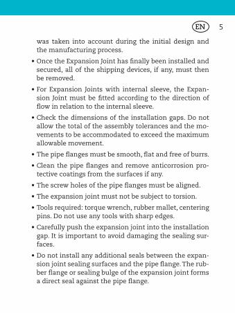
•Once the Expansion Joint has finally been installed and secured, all of the shipping devices, if any, must then be removed.
•For Expansion Joints with internal sleeve, the Expan-sion Joint must be fitted according to the direction of flow in relation to the internal sleeve.
•Check the dimensions of the installation gaps. Do not allow the total of the assembly tolerances and the mo-vements to be accommodated to exceed the maximum allowable movement.
•The pipe flanges must be smooth, flat and free of burrs.
•Clean the pipe flanges and remove anticorrosion pro-tective coatings from the surfaces if any.
•The screw holes of the pipe flanges must be aligned.
•The expansion joint must not be subject to torsion.
•Tools required: torque wrench, rubber mallet, centering pins. Do not use any tools with sharp edges.
•Carefully push the expansion joint into the installation gap. It is important to avoid damaging the sealing sur-faces.
•Do not install any additional seals between the expan-sion joint sealing surfaces and the pipe flange. The rub-ber flange or sealing bulge of the expansion joint forms a direct seal against the pipe flange.

EN6
Right Wrong Right Wrong

EN 7
•Insert the fixing screws and tighten by hand.
•For clearance holes, insert screws with the head toward the expansion joint bellows. Otherwise, select a screw excess length short enough that the screw bolt will not damage the expansion joint bellows when under pres-sure and in the event of movements.
•The sealing surface of the expansion joint should be strained together evenly all around.
•The required clamping torque for the flange screwing should be applied crosswise with a torque wrench in three (3) steps.
NOMINAL BOLT TORQUE Full-Faced Elastomer Flanges MAC-F Series
Pipe Size Torque
in mm ft-lbs Nm
1-2 25-50 30-50 40-68
2.5-5 60-125 50-70 68-95
6-8 150-200 90-120 120-160
10-12 250-300 110-140 150-160
14-16 350-400 130-160 175-215
18-24 450-600 150-200 200-270
26-40 650-1000 200-300 270-410
42-54 1050-1400 300-400 410-540
60-72 1500-1800 400-500 540-680

EN8
Step 1. Apply 1/3 of the final clamping torque crosswise and evenly in approximately three passes. Check the gap width at the outer edge of the flange. Settling time > 30 minutes.
Step 2. Re-tighten all screws crosswise in 3 passes using 2/3 of the final clamping torque. Check the gap width at the outer edge of the flange. Settling time > 60 minutes.
Step 3. Apply the final clamping pressure in 2 passes, cross-wise.
NOMINAL BOLT TORQUE Beaded-Ends (Spherical) MAC-W Series
Pipe Size Torque
in mm ft-lbs Nm
1-1.25 25-32 30-45 40-60
1.5-2 40-50 30-45 40-60
2.5 65 35-50 47-68
3-5 80-125 45-60 60-80
6-8 150-200 50-65 68-88
10-12 250-300 55-75 75-100
14-16 350-400 60-80 80-110
18 450 70-90 95-120
20 500 75-95 95-120
24 600 80-100 110-175
30 750 95-130 120-175

EN 9
•No further retightening needed.
•Do not significantly exceed the indicated maximum clamping torque.
•Protect the expansion joint against damage until com-missioning using a suitable covering.
Prior to starting up•Check if the expansion joint is designed for the
pressure, temperature and medium specified.
•Check for any possible damage during handling or installation.
•Check the outer surface of the expansion joint for signs of deterioration such as discoloration, cracked or grainy surface, or a visible reinforcement layer.
•Ensure that the Expansion Joint fit in the correct place.
•If inner liners are available, make sure that the Expan-sion Joint is properly installed with regards to the direc-tion of flow. Please check the flow direction arrow if any.
•Verify that the Expansion Joint will not be exposed to any contaminants (oil or grease, fuels, acids, or chemi-cals) for which it is not designed.
•Confirm that all of the supporting structures and an-chorage been correctly installed as planned.
•Make sure that the Expansion Joint is not misaligned.

EN10
When starting up•Check for leakage.
•If necessary, check efficiency of tie rods.
When running•The expansion joint must be never covered with insula-
ting material or paint.
•Make sure the expansion joints are not subject to mo-vements beyond their allowable limits.
Expansion joint maintenanceIt is recommended to perform inspections one week after operational start and then every 12 months.
Check for:
•External damages to the bellows, flanges or tie rods.
•Any changes in the outer cover may be indicative of serious deterioration. Changes to the bellows such as blisters, brittleness or tears.
•Make sure the bolts are properly tightened.
•Deformations to the rubber flange or bellows.
•Leaks.
•Condition of the bellows (bulking, hardening, erosions, tears).
EN 11
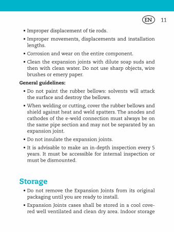
•Improper displacement of tie rods.
•Improper movements, displacements and installation lengths.
•Corrosion and wear on the entire component.
•Clean the expansion joints with dilute soap suds and then with clean water. Do not use sharp objects, wire brushes or emery paper.
General guidelines:
•Do not paint the rubber bellows: solvents will attack the surface and destroy the bellows.
•When welding or cutting, cover the rubber bellows and shield against heat and weld spatters. The anodes and cathodes of the e-weld connection must always be on the same pipe section and may not be separated by an expansion joint.
•Do not insulate the expansion joints.
•It is advisable to make an in-depth inspection every 5 years. It must be accessible for internal inspection or must be dismounted.
Storage•Do not remove the Expansion Joints from its original
packaging until you are ready to install.
•Expansion Joints cases shall be stored in a cool cove-red well ventilated and clean dry area. Indoor storage

EN12
is required at a temperature between +10°C and +20°C and with air humidity between 20% and 70%.
•For long term storage requirements contact MACOGA for specific packing and storage procedures.
•To prevent deterioration of our expansion joints, we re-commend storing them away from ozone generating or fluorescent light sources.
•It is advisable to store them in such a way that they have no contact with the ground.
•Avoid contact with any sharp object.
•Under the above optimum conditions, the expansion joints may be stored for a maximum period of two years from end of manufacture.
•Store the expansion joints in a stress-relieved position without deformations.
•Store expansion joints with mounted steel flanges upright and resting on the flanges.
•Protect the rubber parts from drafts and direct sunlight.
•Do not store any volatile solvents, fuels or other chemi-cals in the same space.

EN 13
Product GuaranteeThe placing of an order by customer implies its comple-te adhesion without reserve to this document and to the exclusion of any other document. This Product Guarantee Document supersede any terms specified on the corres-pondence or the documents of customer. Any additions, erasures, modifications or deletions related to this Docu-ment shall be deemed null and void to the exception of those approved in written by MACOGA.
This warranty is given by MACOGA, S.A. located at Leira s/n - 15680 Ordenes, La Coruña - Spain, for the benefit of the first purchaser of the product to which the warranty applies. This warranty applies to those parts which are manufactured and delivered by MACOGA S.A. exclusively. The warranty is that the parts manufactured and delivered by MACOGA S.A. will be free from defects in material or workmanship under normal use and service for the time specified in this document.
In the event of failure of a part due to such a covered defect, MACOGA will repair or replace, at its option, the defective part at its factory. The part must be returned to the factory by and at the expense of the person claiming the benefit of the warranty.
All products for which warranty claims are made must be returned as delivered to the factory within thirty (30) days from the date of claimed malfunction in order for this warranty to be effective. The only entity authorized to do any warranty repair is MACOGA.
EN14
The warranty shall be for a period of eighteen (18) months after the date of delivery of the product or twelve (12) months after commencement of use of the product, whichever period is the shortest.
This warranty is expressed in lieu of all other warranties, expressed or implied, including the warranty of merchan-tability, the implied warranty of fitness for a particular pur-pose, and of all other obligations or liabilities on the part of MACOGA, and it neither assumes nor authorizes any other persons to assume for MACOGA any other liabilities in connection with the sale of the products.
This warranty does not cover parts of products made by others or products or any part thereof which have been re-paired or altered, except by MACOGA, or which shall have been subjected to misuse, negligence, or accident.
MACOGA shall not be liable for damage or delay suffered by the purchaser regardless of whether such damages are general, special, or consequential in nature, whether cau-sed by defective material or workmanship or otherwise or whether caused by MACOGA’s negligence regardless of the degree.
If goods are defective, the amount of damage is the price of the damaged goods or the accepted repair cost that have been previously approved by a legal representative of MACOGA S.A. only. No allowance will be made for labour or expense of repairing defective goods that have not been formerly approved in writing by a legal representative of MACOGA, S.A.

EN 15
Guarantee is void if goods have been modified, handled inappropriately, if the operating/design conditions are di-fferent to those confirmed in the contract or if the Assem-bly Instructions and Security Recommendations have not been strictly followed.
Goods are considered as accepted by the buyer if after 15 days of receipt of the goods no communication to MACOGA, S.A. has been made in this regard.
This document is “FOR INFORMATION ONLY” and MACOGA does not
accept any liability of the information contained herein. The Purcha-
ser shall be responsible for proper, storage, unpacking, handling and
installation of the Expansion Joints and operating within the desig-
nlimits of the delivered unit(s). Handling, storage, unpacking and
installation of the Expansion Joints shall constitute Purchaser’s sole
and exclusive responsibility.

ES 17
INSTRUCCIONES PARA LA MANIPULACIÓN, MONTAJE Y ALMACENAMIENTO DE COMPENSADORES DE DILATACIÓN DE GOMAEn caso de duda acerca de un procedimiento de instala-ción consultar con el servicio técnico de MACOGA antes de intentar instalar la junta de expansión. La garantía de MA-COGA queda invalidada si se han utilizado procedimientos inadecuados de instalación.
Este documento proporciona orientaciones generales para el almacenamiento adecuado, desembalaje, manipulación y montaje de las juntas de expansión de goma MACOGA.
Con el fin de asegurarse de que la junta de expansión tra-baja adecuadamente y con el fin de prolongar su vida útil, es necesario respetar una serie de precauciones que hacen de las juntas de expansión elementos casi libres de man-tenimiento. Las precauciones más importantes que deben tenerse en cuenta son las siguientes:
Desembalaje y manejo•Desempaquetar las juntas de expansión con cuidado.
•Sólo use objetos redondeados para desempaquetar las juntas de expansión.
ES18
•Si existen, utilizar únicamente los puntos de izado de-signados para izar la junta de expansión.
•No levante la junta de expansión por las barras de transporte.
•No levante la junta de expansión por las bisagras, car-dan, tirantes o cualquier otro dispositivo de operación.
•No fijar cadenas o cuerdas al fuelle. El fuelle de la junta de expansión puede dañarse fácilmente y por lo gene-ral no puede ser reparado.
•Inspeccionar las unidades directamente después de desembalar.
•Si existen, no retire los dispositivos de bloqueo / trans-porte (marcados en amarillo y claramente identifica-dos) hasta que la junta de expansión se haya instalado completamente.
Instalación•Eliminar el polvo o materias extrañas que puedan ha-
berse metido dentro de la junta de expansión.
•Se debe tener especial cuidado para evitar cualquier daño a los fuelles.
•Cualquier pre-posicionamiento o pre-ajuste realizado al instalar las juntas de expansión deben llevarse a cabo de conformidad con las instrucciones específicas suministradas por MACOGA, incluyendo tanto la direc-ción y magnitud del movimiento.

ES 19
•Las juntas de expansión deben ser instaladas en las longitudes apropiadas. Las juntas de expansión no de-ben estirarse o comprimirse con el fin de absorber cual-quier defecto a lo largo de la longitud de la tubería o para rectificar desajustes a menos esto se haya conside-rado en el diseño inicial y en el proceso de fabricación.
•Las juntas de expansión no deben usarse para absorber desalineaciones de las tuberías.
•Una vez que la junta de expansión está instalada y ase-gurada, todos los dispositivos de transporte y bloqueo, si los hay, deben ser retirados.
•Las Juntas de expansión con camisa interior, deben ser montadas de acuerdo a la dirección del flujo en relación con la camisa interna.
•Comprobar las dimensiones de los espacios de instala-ción. No permita que el total de las tolerancias de mon-taje y los movimientos pueden exceder el movimiento máximo permitido.
•Las bridas de la tubería deberán estar lisas, planas y libres de rebabas.
•Limpie la tubería y bridas para eliminar recubrimientos anticorrosivos si los hubiera.
•Los orificios de los tornillos de las bridas de la tubería bridas deben estar alineados. La junta de expansión no debe estar sujeta a la torsión.
•Herramientas necesarias: una llave de torsión, mazo de goma, pasadores de centrado. No utilice herramientas con bordes afilados.
ES20
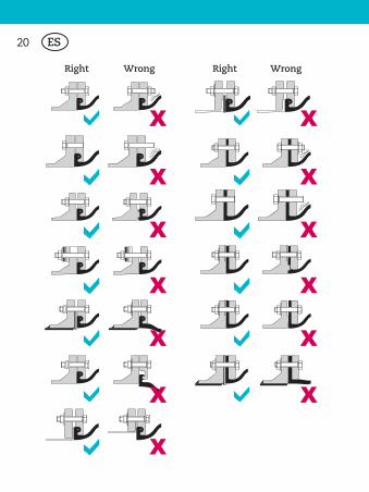
Right Wrong Right Wrong

ES 21
•Coloque con cuidado la junta de expansión en el espa-cio de instalación. Es importante no dañar las caras de sellado de la superficie.
•No instale juntas adicionales entre las superficies de se-llado de las juntas de expansión y la brida de la tubería. La goma de las juntas de expansión forma directamente un sello contra la brida de la tubería.
•Inserte los tornillos de fijación y apriete con la mano.
•Inserte los tornillos con la cabeza hacia el fuelle de la junta de expansión. En caso contrario se debe seleccio-nar un tornillo de distancia lo suficientemente corta
NOMINAL BOLT TORQUE Full-Faced Elastomer Flanges MAC-F Series
Pipe Size Torque
in mm ft-lbs Nm
1-2 25-50 30-50 40-68
2.5-5 60-125 50-70 68-95
6-8 150-200 90-120 120-160
10-12 250-300 110-140 150-160
14-16 350-400 130-160 175-215
18-24 450-600 150-200 200-270
26-40 650-1000 200-300 270-410
42-54 1050-1400 300-400 410-540
60-72 1500-1800 400-500 540-680

ES22
para que la rosca de dicho tornillo no dañe los fuelles de la junta de expansión bajo presión y cuando se pro-duzcan los movimientos.
•La superficie de sellado de la junta de expansión se debe colocar de manera uniforme por todos lados.
•El par de apriete requerido para el atornillado a la brida se debe aplicar en cruz con una llave de torsión en tres (3) pasos.
NOMINAL BOLT TORQUE
Beaded-Ends (Spherical) MAC-W Series
Pipe Size Torque
in mm ft-lbs Nm
1-1.25 25-32 30-45 40-60
1.5-2 40-50 30-45 40-60
2.5 65 35-50 47-68
3-5 80-125 45-60 60-80
6-8 150-200 50-65 68-88
10-12 250-300 55-75 75-100
14-16 350-400 60-80 80-110
18 450 70-90 95-120
20 500 75-95 95-120
24 600 80-100 110-175
30 750 95-130 120-175

ES 23
Paso 1. Aplicar 1/3 del par de apriete final en cruz y uni-formemente en aproximadamente tres pases. Com-pruebe la anchura de la separación en el borde exterior de la brida. Tiempo de estabilización > 30 minutos.
Paso 2. Vuelva a apretar todos los tornillos en cruz en 3 pases utilizando 2/3 del par de apriete final. Compruebe la anchura de la separación en el borde exterior de la brida. Tiempo de asentamiento > 60 minutos.
Paso 3. Aplique el apriete de sujeción final en 2 pasadas, en sentido transversal.
•Ningún otro reapriete es necesario.
•No exceda significativamente el par de apriete máximo indicado.
•Proteja a la junta de expansión de posibles daños has-ta su puesta en marcha utilizando un envoltorio ade-cuado.
Antes de la puesta en marcha•Compruebe si la junta de expansión está diseñada para
la presión, temperatura y fluido especificado.
•Comprobar posibles daños durante el manejo e insta-lación. Compruebe la superficie exterior de la junta de expansión en busca de signos de deterioro, tales como decoloración, grietas o superficie granulada, o capas de refuerzo visibles.
ES24
•Asegúrese de que la junta de expansión encaja en el lugar correcto.
•Si se instalan camisas interiores, asegúrese de que la junta de expansión está instalada correctamente con respecto a la dirección del flujo. Compruebe la direc-ción de la flecha de flujo en su caso.
•Compruebe que la junta de expansión no esté expuesta a cualquier tipo de contaminante (aceite o grasa, com-bustibles, ácidos o productos químicos) para los que no está diseñada.
•Confirmar que todas las estructuras de soporte y an-clajes han sido instaladas correctamente según lo pre-visto.
•Asegúrese que la junta de expansión no está desalineada.
A la puesta en marcha•Compruebe si hay alguna fuga.
•Si necesario, comprobar la eficiencia y operatividad de los tirantes
En operación•La junta de expansión nunca debe cubrirse con mate-
rial de aislamiento o pintura.
•Asegúrese de que las juntas de expansión no están su-jetas a movimientos más allá de sus límites permitidos.
ES 25
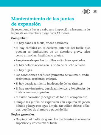
Mantenimiento de las juntas de expansiónSe recomienda llevar a cabo una inspección a la semana de la puesta en marcha y luego cada 12 meses.
Comprobar:
•Si hay daños al fuelle, bridas o tirantes.
•Si hay cambios en la cubierta exterior del fuelle que pueden ser indicativos de un deterioro grave, tales como ampollas, fragilidad o grietas.
•Asegúrese de que los tornillos están bien apretados.
•Si hay deformaciones en la brida de caucho o fuelle.
•Si hay fugas.
•Las condiciones del fuelle (aumento de volumen, endu-recimiento, erosiones, grietas).
•Si hay desplazamiento inadecuado de los tirantes.
•Si hay movimientos, desplazamientos y longitudes de instalación inapropiados.
•Si existe corrosión y desgaste de todo el componente.
•Limpie las juntas de expansión con espuma de jabón diluido y luego con agua limpia. No utilice objetos afila-dos, cepillos de alambre o papel de lija.
Reglas generales:
•No pintar el fuelle de goma: los disolventes atacarán la superficie y destruirán el fuelle.
ES26
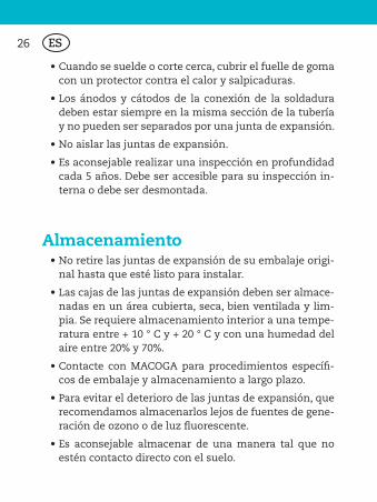
•Cuando se suelde o corte cerca, cubrir el fuelle de goma con un protector contra el calor y salpicaduras.
•Los ánodos y cátodos de la conexión de la soldadura deben estar siempre en la misma sección de la tubería y no pueden ser separados por una junta de expansión.
•No aislar las juntas de expansión.
•Es aconsejable realizar una inspección en profundidad cada 5 años. Debe ser accesible para su inspección in-terna o debe ser desmontada.
Almacenamiento•No retire las juntas de expansión de su embalaje origi-
nal hasta que esté listo para instalar.
•Las cajas de las juntas de expansión deben ser almace-nadas en un área cubierta, seca, bien ventilada y lim-pia. Se requiere almacenamiento interior a una tempe-ratura entre + 10 ° C y + 20 ° C y con una humedad del aire entre 20% y 70%.
•Contacte con MACOGA para procedimientos específi-cos de embalaje y almacenamiento a largo plazo.
•Para evitar el deterioro de las juntas de expansión, que recomendamos almacenarlos lejos de fuentes de gene-ración de ozono o de luz fluorescente.
•Es aconsejable almacenar de una manera tal que no estén contacto directo con el suelo.

ES 27
•Evitar el contacto con cualquier objeto afilado.
•Bajo las condiciones óptimas anteriores, las juntas de expansión pueden ser almacenadas por un periodo máximo de dos años a partir de la fecha de fabricación.
•Almacenar las juntas de expansión en una posición sin tensiones y sin deformaciones.
•Almacenar las juntas de expansión con las bridas me-tálicas en posición vertical y apoyada sobre las bridas.
•Proteger las piezas de goma de la luz solar directa.
•No almacenar disolventes volátiles, combustibles u otros productos químicos en el mismo lugar.
Garantía de productoLa realización de un pedido por el cliente implica su com-pleta adhesión sin reservas a este Documento, con exclu-sión de cualquier otro documento. Las presentes Garantías de Producto sustituyen cualquier término especificado en la correspondencia o los documentos de los clientes. Toda adición, tachaduras, modificaciones o supresiones en rela-ción con estas Garantías se considerarán nulos y sin efecto a la excepción de las aprobadas por escrito por MACOGA. Toda la información y documentación disponible en la ver-sión en español del presente documento se proporciona únicamente a efectos informativos. En caso de discrepan-cia entre el contenido de la versión en español y el de la versión en inglés prevalecerá el de esta última.

ES28
Esta garantía está dada por MACOGA, SA ubicada en Leira s / n - 15680 Ordenes, La Coruña - España, para el beneficio del primer comprador del producto objeto de la garantía. Esta garantía se aplica a aquellas partes que son fabricadas y entregadas por MACOGA SA exclusivamente.
La garantía es que las piezas fabricadas y entregadas por MACOGA SA están libres de defectos en materiales o mano de obra bajo uso normal y servicio durante el tiempo espe-cificado en este documento. En caso de fallo de una pieza, debido a un defecto cubierto, MACOGA reparará o reem-plazará, a su elección, las partes defectuosas en su fábrica de Ordenes, La Coruña. La pieza deberá ser devuelta a la fábrica por la persona que solicita el beneficio de la garan-tía. Todos los productos para los que se hacen las reclama-ciones de garantía deben ser devueltos y entregados a la fábrica dentro de los treinta (30) días a partir de la fecha de reclamación para que esta garantía sea efectiva. La úni-ca entidad autorizada para hacer cualquier reparación en garantía es MACOGA. La garantía será por un período de dieciocho (18) meses después de la fecha de entrega del producto o doce (12) meses después del inicio del uso del producto si este período fuese más corto.
Esta garantía se expresa en lugar de todas las demás ga-rantías, expresas o implícitas, incluyendo la garantía de comerciabilidad, la garantía implícita de aptitud para un propósito particular y todas las demás obligaciones y responsabilidades. MACOGA que no asume ni autoriza a cualquier otra persona a adjudicarse cualquier otra res-ponsabilidad en relación con la venta de los productos.

ES 29
Esta garantía no cubre las piezas de productos de otros fabricantes ni cualquier producto o parte del mismo que haya sido reparado o alterado excepto por MACOGA o que haya sido objeto de uso incorrecto, negligencia o accidente.
MACOGA no será responsable del daño o el retraso sufrido por el comprador, independientemente de si tales daños son de carácter general, especial o indirecto, ya sea cau-sado por defectos de materiales o mano de obra o de otro modo, o sea causado por negligencia de MACOGA indepen-dientemente de su alcance.
Si los productos son considerados defectuosos por parte de MACOGA, el importe máximo del daño es el precio de los bienes afectados o el costo de reparación si es que éste coste ha sido previamente aprobado por un representante legal de MACOGA SA. Ninguna concesión se hará a mano de obra o gastos de reparación de productos defectuosos que no hayan sido aprobados anteriormente por escrito por un representante legal de MACOGA. La Garantía no es válida si los bienes han sido modificados, manejados inadecuadamente o si las condiciones de operación o de diseño son diferentes a los confirmadas en el contrato o si las Instrucciones y Recomendaciones de seguridad no se han seguido estrictamente.
Las mercancías se considerarán aceptadas por el compra-dor si transcurridos 15 días desde la recepción no ha habi-do comunicación con MACOGA, S.A. en este sentido.
ES30
Este documento es “sólo para información» y MACOGA no asume responsabilidad alguna de la información contenida en el presente documento. El comprador es responsable del correcto almacena-miento, desembalaje, manipulación e instalación de las juntas de expansión y de operarlas dentro de los límites de diseño de la uni-dad(s) entregada(s). La manipulación, almacenamiento, desembalaje e instalación de las Juntas de expansión son responsabilidad del comprador.


ENGINEERED EXPANSION JOINTS
Leira. s/n. 15680 Ordenes. La Coruña, Spain. Tel: +34 981 68 00 00. Fax: +34 981 68 02 38www.macoga.com e-mail: [email protected]