Assembly Instructions for the Rolling Harrow 6-26-03
7
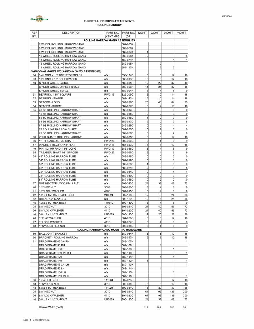
Assembly Instructions for the Rolling Harrow and Board Turbo-Till 6/26/03 Your initial action is to locate the correct drag frame [(61) 589-107H through 589-116H]. Bolt the drag frame to the rear drag plates located on the rear of your Great Plains Turbo Till, using 5/8x1 ½ hex bolts [(43) 802-051C] with 5/8” hex nuts [(25) 803-021C] and 5/8” lock washers [(26) 804-022C]. The rolling harrow gangs shown in figure 4 will come to you partially assembled. To finish assembly, refer to the table in figure 4 and assemble accordingly. Start by locating the correct rolling harrow tube, center it over your partial assembly on the bearing hangers [(52) 589-142H], and mount the tube using 5/8x3x4 ½ U-bolts [(44) 806-183C] with a lock washer and nut. Your next step is to locate the ball joint assemblies [(59) 589-064H]. Figure 4 shows you the dimensions to mount the ball joint assemblies on the rolling harrow tube. Count the number of each assembly in figures 1-3 and assemble accordingly. Mount the rolling harrow brackets [(60) 589-057H] to the under side of the drag frames according to the dimensions in figures 1-3, using a 5/8x3x4 ½ U-bolt [(44) 806-183C] with a lock washer and nut. You may tighten the U-bolts on all the brackets that are closest to the rear of the machine. Leave the front brackets loose to slide until the rolling harrow assemblies are hung under the frame. Use the 1x4 hex bolt and 1” nylock nut through the harrow brackets (589-057H) and ball joint assemblies [(59) 589-064H] to hang the rolling harrow assemblies under the frame. Be careful to put the proper gang in the proper location and be sure that the assemblies are oriented correctly as shown in figure 4. When all gangs are hung under the frame, tighten the remaining U-bolts Mount the rear stand bracket [(71) 580-049H], if applicable, to the drag frame with 5/8x4x4 ¼ U-bolts, a lock washer and a nut as shown on figure 1. The rear stand leg [(70) 560-196H] should be pinned in the rear stand bracket with a 3/4x4 ½ pin and retainer (805-081C). Mount the reel arm assemblies (589-069L) to the drag frames, using the dimensions in figures 6- 10, using a 5/8x3x4 ½ U-bolt [(44) 806-183C] with a lock washer and nut. These bolts may be tightened at this time. Mount the leveling board mounting tube (32) using a 5/8x2 1/2x3 ¾ U-bolt [(16) UB0037] with a lock washer and nut, according to the dimensions and locations in figures 6-10. Be sure to bolt on the correct mounting tube in the correct location. These bolts may be tightened at this time. Use the 5/8X3 hex bolt with a lock washer and nut through the mounting tube and the leveling board arm [(30) 589-073H] to hang the arms. Use ½x2 ½ carriage bolts [(43) 802-571C] with a ½” lock washer and ½” nut [(41) 804-015C - (40) 803-020C] to mount the leveling board on the arms. The leveling board part numbers will be marked on figures 6-10 to be sure the correct level board is mounted in the correct location. Check the dimension in between the leveling boards on each section to be sure there remains about 1” of gap in between them. If the boards are not about 1” apart, recheck the leveling board mounting tube dimensions. There should be about 5” in-between the leveling boards between the center section and each wing.
Transcript of Assembly Instructions for the Rolling Harrow 6-26-03
Assembly Instructions for the Rolling Harrow and BoardTurbo-Till
6/26/03
Your initial action is to locate the correct drag frame [(61) 589-107H through 589-116H]. Boltthe drag frame to the rear drag plates located on the rear of your Great Plains Turbo Till, using 5/8x1 ½hex bolts [(43) 802-051C] with 5/8” hex nuts [(25) 803-021C] and 5/8” lock washers [(26) 804-022C].The rolling harrow gangs shown in figure 4 will come to you partially assembled. To finish assembly,refer to the table in figure 4 and assemble accordingly. Start by locating the correct rolling harrow tube,center it over your partial assembly on the bearing hangers [(52) 589-142H], and mount the tube using5/8x3x4 ½ U-bolts [(44) 806-183C] with a lock washer and nut. Your next step is to locate the ball jointassemblies [(59) 589-064H]. Figure 4 shows you the dimensions to mount the ball joint assemblies onthe rolling harrow tube. Count the number of each assembly in figures 1-3 and assemble accordingly.
Mount the rolling harrow brackets [(60) 589-057H] to the under side of the drag framesaccording to the dimensions in figures 1-3, using a 5/8x3x4 ½ U-bolt [(44) 806-183C] with a lockwasher and nut. You may tighten the U-bolts on all the brackets that are closest to the rear of themachine. Leave the front brackets loose to slide until the rolling harrow assemblies are hung under theframe. Use the 1x4 hex bolt and 1” nylock nut through the harrow brackets (589-057H) and ball jointassemblies [(59) 589-064H] to hang the rolling harrow assemblies under the frame. Be careful to put theproper gang in the proper location and be sure that the assemblies are oriented correctly as shown infigure 4. When all gangs are hung under the frame, tighten the remaining U-bolts
Mount the rear stand bracket [(71) 580-049H], if applicable, to the drag frame with 5/8x4x4 ¼U-bolts, a lock washer and a nut as shown on figure 1. The rear stand leg [(70) 560-196H] should bepinned in the rear stand bracket with a 3/4x4 ½ pin and retainer (805-081C).
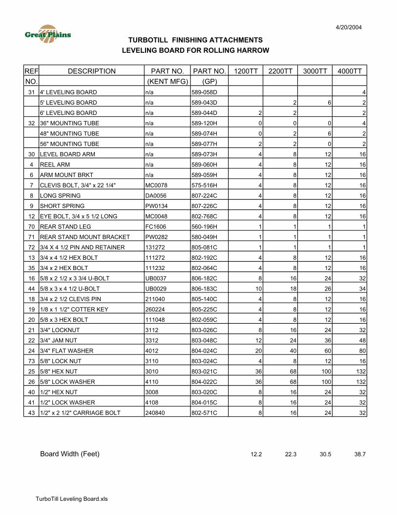
Mount the reel arm assemblies (589-069L) to the drag frames, using the dimensions in figures 6-10, using a 5/8x3x4 ½ U-bolt [(44) 806-183C] with a lock washer and nut. These bolts may betightened at this time. Mount the leveling board mounting tube (32) using a 5/8x2 1/2x3 ¾ U-bolt [(16)UB0037] with a lock washer and nut, according to the dimensions and locations in figures 6-10. Be sureto bolt on the correct mounting tube in the correct location. These bolts may be tightened at this time.Use the 5/8X3 hex bolt with a lock washer and nut through the mounting tube and the leveling boardarm [(30) 589-073H] to hang the arms. Use ½x2 ½ carriage bolts [(43) 802-571C] with a ½” lockwasher and ½” nut [(41) 804-015C - (40) 803-020C] to mount the leveling board on the arms. Theleveling board part numbers will be marked on figures 6-10 to be sure the correct level board is mountedin the correct location. Check the dimension in between the leveling boards on each section to be surethere remains about 1” of gap in between them. If the boards are not about 1” apart, recheck the levelingboard mounting tube dimensions. There should be about 5” in-between the leveling boards between thecenter section and each wing.


4/20/2004
REF DESCRIPTION PART NO. PART NO. 1200TT 2200TT 3000TT 4000TTNO. (KENT MFG) (GP)
7 WHEEL ROLLING HARROW GANG 589-065K8 WHEEL ROLLING HARROW GANG 589-066K9 WHEEL ROLLING HARROW GANG 589-067K 110 WHEEL ROLLING HARROW GANG 589-068K 2 511 WHEEL ROLLING HARROW GANG 589-071K 4 412 WHEEL ROLLING HARROW GANG 589-095K 213 WHEEL ROLLING HARROW GANG 589-117K 2 2
(INDIVIDUAL PARTS INCLUDED IN GANG ASSEMBLIES)64 3/4 LONG X 1/2 TINE STOP/SPACR n/a 550-134D 6 8 12 1863 1/2 LONG X 1/2 BOLT SPACER n/a 585-013D 6 8 12 1850 SPIDER WHEEL LARGE n/a 589-055H 12 22 32 40
SPIDER WHEEL OFFSET @ 22.5 n/a 589-056H 14 24 32 45SPIDER WHEEL SMALL n/a 589-094H 3 4 6 9
51 BEARING, 1 1/4" SQUARE PW0115 822-209C 6 10 14 1852 BEARING HANGER n/a 589-142H 6 10 14 1853 SPACER - LONG n/a 589-026D 26 46 64 8554 SPACER - SHORT n/a 589-027D 6 12 16 1855 43 7/8 ROLLING HARROW SHAFT n/a 589-014D 0 0 0 0
49 5/8 ROLLING HARROW SHAFT n/a 589-015D 0 0 0 055 1/2 ROLLING HARROW SHAFT n/a 589-016D 1 0 0 061 3/8 ROLLING HARROW SHAFT n/a 589-017D 2 0 0 567 1/8 ROLLING HARROW SHAFT n/a 589-029D 0 0 4 473 ROLLING HARROW SHAFT n/a 589-050D 0 2 0 079 3/8 ROLLING HARROW SHAFT n/a 589-056D 0 2 2 0
66 ZERK GUARD ROLLING HARROW n/a 589-085D 6 8 12 1856 1" THREADED STUB SHAFT PW0126 800-364C 3 4 6 957 WASHER, RECT 1/4X1" FLAT PW0116 585-057D 6 8 12 1849 PIN, 1/2" HR RND 1 3/8" LONG PW0140 585-056D 3 4 6 965 TREADER SHAFT 1/8" SPACER PW0427 585-066D 3 4 6 958 48" ROLLING HARROW TUBE n/a 589-018D 0 0 0 0
54" ROLLING HARROW TUBE n/a 589-019D 0 0 0 060" ROLLING HARROW TUBE n/a 589-020D 1 0 0 066" ROLLING HARROW TUBE n/a 589-021D 2 0 0 572" ROLLING HARROW TUBE n/a 589-031D 0 0 4 478" ROLLING HARROW TUBE n/a 589-049D 0 2 0 084" ROLLING HARROW TUBE n/a 589-055D 0 2 2 0
67 NUT HEX TOP LOCK 1/2-13 PLT n/a 803-342C 24 32 48 7240 1/2" HEX NUT 3008 803-020C 3 4 6 941 1/2" LOCK WASHER 4108 804-015C 3 4 6 942 1/2 x 1 1/2" CARRIAGE BOLT 240824 802-106C 12 16 24 3662 RHSNB 1/2-13X2 GR5 n/a 802-129C 12 16 24 3645 1/2 x 2 1/2" HEX BOLT 110540 802-130C 3 4 6 925 5/8" HEX NUT 3010 803-021C 24 40 56 7226 5/8" LOCK WASHER 4110 804-022C 24 40 56 7244 5/8 x 3 x 4 1/2" U-BOLT UB0029 806-183C 12 20 28 3646 1" FLAT WASHER 4016 804-028C 6 8 12 1847 1" LOCK WASHER 4116 804-027C 3 4 6 948 1" NYLOCK HEX NUT 3616 803-038C 3 4 6 9
59 BALL JOINT BRACKET n/a 589-064H 6 8 12 1860 BRACKET - ROLLING HARROW n/a 589-057H 6 8 12 1861 DRAG FRAME 43 3/4 RH n/a 589-107H 1
DRAG FRAME 56 RH n/a 589-108H 1DRAG FRAME 106 RH n/a 589-109H 1DRAG FRAME 109 1/2 RH n/a 589-110H 1DRAG FRAME 129 n/a 589-111H 1 1DRAG FRAME 149 n/a 589-112H 1 1DRAG FRAME 43 3/4 LH n/a 589-113H 1DRAG FRAME 56 LH n/a 589-114H 1DRAG FRAME 106 LH n/a 589-115H 1DRAG FRAME 109 1/2 LH n/a 589-116H 1
36 1 x 4 HEX BOLT 111664 802-073C 6 8 12 1848 1" NYLOCK NUT 3616 803-038C 6 8 12 1843 5/8 x 1 1/2" HEX BOLT 111024 802-051C 16 32 40 5625 5/8" HEX NUT 3010 803-021C 64 96 136 20026 5/8" LOCK WASHER 4110 804-022C 64 96 136 20044 5/8 x 3 x 4 1/2" U-BOLT UB0029 806-183C 24 32 48 72
Harrow Width (Feet) 11.7 20.6 28.7 38.1
TURBOTILL FINISHING ATTACHMENTSROLLING HARROW
ROLLING HARROW GANG ASSEMBLIES
ROLLING HARROW GANG MOUNTING HARDWARE
TurboTill Rolling Harrow.xls

4/20/2004
REF DESCRIPTION PART NO. PART NO. 1200TT 2200TT 3000TT 4000TTNO. (KENT MFG) (GP)31 4' LEVELING BOARD n/a 589-058D 4
5' LEVELING BOARD n/a 589-043D 2 6 2
6' LEVELING BOARD n/a 589-044D 2 2 2
32 36" MOUNTING TUBE n/a 589-120H 0 0 0 4
48" MOUNTING TUBE n/a 589-074H 0 2 6 2
56" MOUNTING TUBE n/a 589-077H 2 2 0 2
30 LEVEL BOARD ARM n/a 589-073H 4 8 12 16
4 REEL ARM n/a 589-060H 4 8 12 16
6 ARM MOUNT BRKT n/a 589-059H 4 8 12 16
7 CLEVIS BOLT, 3/4" x 22 1/4" MC0078 575-516H 4 8 12 16
8 LONG SPRING DA0056 807-224C 4 8 12 16
9 SHORT SPRING PW0134 807-226C 4 8 12 16
12 EYE BOLT, 3/4 x 5 1/2 LONG MC0048 802-768C 4 8 12 16
70 REAR STAND LEG FC1606 560-196H 1 1 1 1
71 REAR STAND MOUNT BRACKET PW0282 580-049H 1 1 1 1
72 3/4 X 4 1/2 PIN AND RETAINER 131272 805-081C 1 1 1 1
13 3/4 x 4 1/2 HEX BOLT 111272 802-192C 4 8 12 16
35 3/4 x 2 HEX BOLT 111232 802-064C 4 8 12 16
16 5/8 x 2 1/2 x 3 3/4 U-BOLT UB0037 806-182C 8 16 24 32
44 5/8 x 3 x 4 1/2 U-BOLT UB0029 806-183C 10 18 26 34
18 3/4 x 2 1/2 CLEVIS PIN 211040 805-140C 4 8 12 16
19 1/8 x 1 1/2" COTTER KEY 260224 805-225C 4 8 12 16
20 5/8 x 3 HEX BOLT 111048 802-059C 4 8 12 16
21 3/4" LOCKNUT 3112 803-026C 8 16 24 32
22 3/4" JAM NUT 3312 803-048C 12 24 36 48
24 3/4" FLAT WASHER 4012 804-024C 20 40 60 80
73 5/8" LOCK NUT 3110 803-024C 4 8 12 16
25 5/8" HEX NUT 3010 803-021C 36 68 100 132
26 5/8" LOCK WASHER 4110 804-022C 36 68 100 132
40 1/2" HEX NUT 3008 803-020C 8 16 24 32
41 1/2" LOCK WASHER 4108 804-015C 8 16 24 32
43 1/2" x 2 1/2" CARRIAGE BOLT 240840 802-571C 8 16 24 32
Board Width (Feet) 12.2 22.3 30.5 38.7
LEVELING BOARD FOR ROLLING HARROWTURBOTILL FINISHING ATTACHMENTS
TurboTill Leveling Board.xls