ASCENSOR AUTO
4
Data Sheet Wöhr Carlift (in accordance with EN 81-2) Wöhr carlifts provide an access from street level to parking areas without the need for ramps. Both the vehicle and driver are transported quickly and conveniently to parking levels either above or below the entrance level. In conjunction with the Wöhr range of mechanical parking systems, the carlifts offer a complete space-saving solution. AUTO WOH R PARKSYSTEME Otto Wöhr GmbH Postfach 1151 D-71288 Friolzheim Phone ++49-70 44-46-0 Fax ++49-70 44-46-200 E-Mail: info@ woehr.de Internet: http://www. woehr.de We compact parking space
-
Upload
popescu-mircea-iulian -
Category
Documents
-
view
10 -
download
0
description
A
Transcript of ASCENSOR AUTO

Data Sheet Wöhr Carlift(in accordance with EN 81-2)
Wöhr carlifts provide an access from street level to parking areas without the need for ramps. Both the vehicle and driver are transported quickly and conveniently to
parking levels either above or below the entrancelevel. In conjunction with the Wöhr range ofmechanical parking systems, the carlifts offer acomplete space-saving solution.
AU TOW O H R
PAR KSYS TE M E
Otto Wöhr GmbHPostfach 1151D-71288 Friolzheim
Phone ++49-70 44-46-0Fax ++49-70 44-46-200
E-Mail: [email protected]: http://www. woehr.de
We compact parking space
2
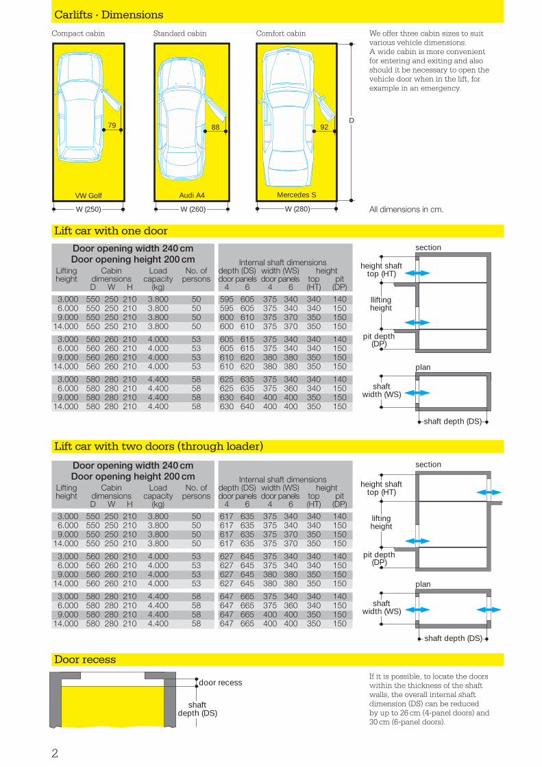
We offer three cabin sizes to suitvarious vehicle dimensions. A wide cabin is more convenient for entering and exiting and also should it be necessary to open thevehicle door when in the lift, forexample in an emergency.
Door opening width 240 cmDoor opening height 200 cm
Lifting Cabin Load No. ofheight dimensions capacity persons
D W H (kg)
Carlifts · Dimensions
Compact cabin Standard cabin Comfort cabin
Lift car with one door
Lift car with two doors (through loader)
Door recess
Internal shaft dimensionsdepth (DS) width (WS) heightdoor panels door panels top pit
4 6 4 6 (HT) (DP)
height shafttop (HT)
lliftingheight
pit depth(DP)
section
shaft depth (DS)
shaftwidth (WS)
plan
height shafttop (HT)
shaft depth (DS)
liftingheight
pit depth(DP)
shaftwidth (WS)
section
plan
Door opening width 240 cmDoor opening height 200 cm
Lifting Cabin Load No. ofheight dimensions capacity persons
D W H (kg)
Internal shaft dimensionsdepth (DS) width (WS) heightdoor panels door panels top pit
4 6 4 6 (HT) (DP)
92
W (280)
Mercedes S
D
shaftdepth (DS)
door recessIf it is possible, to locate the doorswithin the thickness of the shaftwalls, the overall internal shaftdimension (DS) can be reducedby up to 26 cm (4-panel doors) and30 cm (6-panel doors).
VW Golf
W (250)
79
W (260)
Audi A4
88
All dimensions in cm.
3.000 550 250 210 3.800 50 595 605 375 340 340 1406.000 550 250 210 3.800 50 595 605 375 340 340 1509.000 550 250 210 3.800 50 600 610 375 370 350 150
14.000 550 250 210 3.800 50 600 610 375 370 350 150
3.000 560 260 210 4.000 53 605 615 375 340 340 1406.000 560 260 210 4.000 53 605 615 375 340 340 1509.000 560 260 210 4.000 53 610 620 380 380 350 150
14.000 560 260 210 4.000 53 610 620 380 380 350 150
3.000 580 280 210 4.400 58 625 635 375 340 340 1406.000 580 280 210 4.400 58 625 635 375 360 340 1509.000 580 280 210 4.400 58 630 640 400 400 350 150
14.000 580 280 210 4.400 58 630 640 400 400 350 150
3.000 550 250 210 3.800 50 617 635 375 340 340 1406.000 550 250 210 3.800 50 617 635 375 340 340 1509.000 550 250 210 3.800 50 617 635 375 370 350 150
14.000 550 250 210 3.800 50 617 635 375 370 350 150
3.000 560 260 210 4.000 53 627 645 375 340 340 1406.000 560 260 210 4.000 53 627 645 375 340 340 1509.000 560 260 210 4.000 53 627 645 380 380 350 150
14.000 560 260 210 4.000 53 627 645 380 380 350 150
3.000 580 280 210 4.400 58 647 665 375 340 340 1406.000 580 280 210 4.400 58 647 665 375 360 340 1509.000 580 280 210 4.400 58 647 665 400 400 350 150
14.000 580 280 210 4.400 58 647 665 400 400 350 150

3
Carlifts · Door Panels
Drive unittravel speed rated electricity number of
(m/sec) wattage (A) run cyclesup down (kW) rated start per hour
Landing doors with four door panels Landing doors with six door panels For doors with four panels the shaft will be slightly wider but not so long. Six panel doors will require the shaftto be a little narrower and longer.
Traffic Light Control
waiting areatraffic lights(red/green)
Traffic lights are part of standard equipment. Waiting areasand entries/exits to roads are an individual requirementand subject to relevant approval from Local Authorities.
Conveying CapacityThe basic program along with thestandard guide values are depicted here. If required, we can supplyintermediate dimensions or other technically feasible drive unit combinations, for example with higher capacities.
Lifting Cabin loadheight dimensions capacity
D W H (kg)
Appropriate Number of Runs
An increase in the number of runs leads to an exceptionallyhigh increase in drive wattage, and thus of the costs for theunit. Increasing travelling speed does not lead to a much higher number of runs, as other factors are involved. This can be seen from the diagram on the left showing a carliftwith a lifting height of three metres which makes two stops.In general, 30 cars can be conveyed to the parking places per hour.
runs
per
hou
r
travelling speed (m/sec)0,28 0,32 0,38 0,43 0,54 0,64 0,75 0,86
33
32
31
30
29
28
27
runs
per
hou
r
drive wattage (kW)35 40 47 53 67 78 94 106
33
32
31
30
29
28
27
6.000 550 250 200 3.80014.000 550 250 200 3.800
6.000 560 260 210 4.00014.000 560 260 210 4.000
6.000 580 280 210 4.40014.000 580 280 210 4.400
0,31 33 70 105 300,31 40 84 126 30
0,31 33 70 105 300,31 40 84 126 30
0,31 40 84 126 300,31 40 84 126 30
Vehicle positioning in the cabin
The vehicle positioning system reassures the driver that his vehicle is correctly positioned to avoid contactwith the closing doors. If one of thegreen buttons lights up when entering,the vehicle should be driven backwardsor forwards as indicated by the arrow.When correctly positioned the greenlight goes out and the red STOP buttonlights up. The driver can now activatethe lift and the doors close. Once the destination has been reached a greenlight indicates the direction of exit. Thedisplay panel can either be mounted in the main operating panel or in thedoor frame depending upon clearancebetween overall cabin width and dooropening width.
Photo electriclight barrier
backwardsforwards
Operating panelin the cabin
Variant 1 Variant 2
forwards
backwards
Door frame

4
Shaft EquipmentFor a lift height of up to 3meters the lift car is directlyraised and lowered by twooffset hydraulic rams. Thissystem is equipped with apipe rupture valve safetysystem. Lift heights in excess of 3 metres utilise an indirect hydraulic systemincorporating a rope sheavearrangement, with speedgovernors and safety stopdevices. Guide rails, fitted to the shaft walls, ensure
smooth travel. The four or six panel doors open auto-matically with the lift cardoors.
All fastenings from cylinders,guide rails and landing doorsare adjustable screwed on halfen channels which has to be casted in concreteaccording to our drawings.Also scaffold sockets on thewalls and eye beams on theceiling from the shaft.
Door controlAC/DC pulse control with adjustable door opening times. As in 10.2002 C027-5211
Lift carThe sturdily constructed lift car consists of an outerfabricated frame supportingthe cabin which is insulatedagainst noise and vibration.
The four or six panel doorsopen and close automatically.Other lift car equipment isshown above.
Machine RoomA separate machine roomcontains the hydraulic pumpunit and electric controlpanel (in the control cabinet).The radiated heat must beremoved by ventilation andaeration units to be fitted by the customer. We recom-mend that the machine roomis located adjacent to the
shaft on the level of the lowest floor and not on afacing side. Minimum clearance dimensions:
Height 200 cm, width 180 cm,Length 240 cm, door opening90 cm.
Other configurations anddimensions on request.
Hydraulic Power PackIs a low noise sub-oil modelwith a 380/400 V submersibleoil motor in star delta startingconfiguration, a low pulsationscrew pump and a pulsationsilencer. If the motor coiltemperature reaches 100° Cor the oil temperature risesto 70° C, the system is stop-ped. The temperature in themachine room should bebetween 15° and 35° C. The
unit must be air-ventilated.Oil heaters and oil coolerscan be installed if necessary.The electro-hydraulic controlguarantees smooth travellingin the lift in all situations. Pressure switches emits signals to shutdown thesystem if the permissiblemaximum load is reached or the pressure falls below the minimum limit.
Electronic Lift ControlElectronic microprocessordown collective control.In addition to the standard lift equipment, the following functions are integrated:– fault memory– diagnosis interface
– motor PTC thermistor protection
– inspection drive – correction drive – signal device – remote control (optional)– oil cooler control (optional)– cabin ventilator (optional)
A service technican for lifts is on call for emergencies
A skilled service technican is on call 24 hours a day for maintenance and in the event of emergency call out.
Carlifts · Lift Cars
Light screenbetween carand landingdoor 190 cmhigh
Stainless steelcar control panel:– manufacturers
nameplate– car position
indicator– emergency light or
overload warning– emergency call– drive control
push button withconfirm light
– doors open/closepush button
– emergency callpush button
Car and landingdoors 4 or 6panels withautomatic centralopening.Panels and frameswith basic painting.Fire protected inaccordance withDIN 18091.
Call panelwith display»Lift coming«
Key-operatedswitch for calland door opening
Remote controloptional
Other equipmenton request
Sheet steel,painted white
Ventilationopenings
Green and redtraffic lights
Countersunkceiling lights
Car control panel
Side panelsprotected with2 wooden bars
Photo electriclight barrier toconfirm position
Side wall panelswith electrolyticgalvanized finish
Patterned steelbase plate,basic painted
Door framebasic painted
Display for vehiclepositioning in thecabin door frame
NotesWe reserve the right to make design changes. We reserve theright to change construction details on the basis of techno-logical progress and in the light of environment regulations.