bjectivesunits.flwg.us/resources/site4458/General/Cadet Area/Aero... · Web viewFlight Navigation...
50
“Navigation is the science of getting ships, aircraft or spacecraft from place to place . . . the method of determining position, course and distance traveled.” This is what one dictionary says about navigation. For purposes here, the dictionary’s definition will be simplified to say that navigation is knowing where you are, where you are going and how to get there. We could say that each of us navigates in order to get from place to place during our daily activities. In familiar territory, we navigate without thinking by following the right streets and making proper changes in direction to get to our destinations. If time is a concern, we estimate how long it will take us to travel the required distance. To assist navigational tasks, descriptive city and road maps are used when going into unfamiliar territory. Hunters, explorers and others going into unmarked territories use special types of maps (topographic) and direction-indicating instruments (compasses) to help them navigate through the territory. Aviators and seafarers are even more concerned with maps and direction-indicating instruments because they may not be able to see the land for long periods of travel. The aviator cannot simply stop by the local convenience store and ask for directions. 235
-
Upload
truongmien -
Category
Documents
-
view
216 -
download
2
Transcript of bjectivesunits.flwg.us/resources/site4458/General/Cadet Area/Aero... · Web viewFlight Navigation...
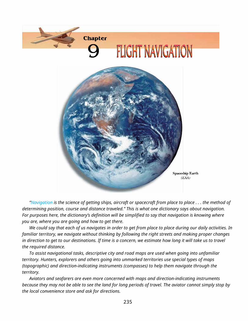
“Navigation is the science of getting ships, aircraft or spacecraft from place to place . . . the method of determining position, course and distance traveled.” This is what one dictionary says about navigation. For purposes here, the dictionary’s definition will be simplified to say that navigation is knowing where you are, where you are going and how to get there.
We could say that each of us navigates in order to get from place to place during our daily activities. In familiar territory, we navigate without thinking by following the right streets and making proper changes in direction to get to our destinations. If time is a concern, we estimate how long it will take us to travel the required distance.
To assist navigational tasks, descriptive city and road maps are used when going into unfamiliar territory. Hunters, explorers and others going into unmarked territories use special types of maps (topographic) and direction-indicating instruments (compasses) to help them navigate through the territory.
Aviators and seafarers are even more concerned with maps and direction-indicating instruments because they may not be able to see the land for long periods of travel. The aviator cannot simply stop by the local convenience store and ask for directions.
Navigation principles are generally the same for any type navigation. They do, however, involve considerable detail when a navigation problem is complex. An examination of these basic principles is given in this chapter. However, remember that pilots must learn (and practice) much more than is discussed here.
235

bjectivesExplain how a grid is constructed to provide a system of coordinates for use on a map. Identify the terms “small circle” and “great circle.” Describe how the coordinates of a location are written.Describe which map projections are used for what purposes.Define prime meridian, equator, hemisphere, parallels, meridians and graticule.Describe the purposes served by sectional aeronautical charts.Name methods of showing relief on a sectional aeronautical chart.Identify symbols used to indicate cultural features on a sectional aeronautical chart.Explain why hydrographic features are a valuable navigational aid.Name the two broadest classifications of airports.Describe an airport using the symbols and data printed on a sectional aeronautical chart.Define joint-use airports.Name the agency responsible for regulating planes, pilots and airspace.Describe controlled airspace and its subdivisions.Identify special-use airspace categories.Describe the functions of specialized aeronautical charts.Identify the major factors influencing air navigation.State two causes of magnetic variation.Explain why compass deviation occurs.Describe the purpose of a wind triangle.Define true airspeed and ground speed.Explain pilotage navigation.Describe dead-reckoning navigation.Identify the basic steps involved in dead-reckoning navigation.Describe the use of the aircraft radio as a navigational aid.Explain the use of the VOR/TACAN receiver as a navigational aid.Identify limitations of the automatic direction finder (ADF) as a navigational aid.Describe the use of distance-measuring equipment (DME) as a navigational aid.Name the parts of the VOR System for navigation. Describe how to navigate using the VOR System Describe how to plot a position on a LORAN chart. Name the two types of GPS positioning systems and who might use each. Describe why the Inertial Navigation System is different than the other systems. Describe three types of landing systems.
Maps and Map Projections
236

236The ability to navigate through the air is not much more difficult than following a road map. It is
simply more important to know and record where you have started from, where you were heading and how long you have been flying at a certain speed. Without roads to follow, the pilot can become lost easily if he flies the wrong way. Without signs to read along the way, the pilot might miss a turn.
Understanding navigation is best accomplished by first understanding the maps used. Let’s start with some aviation charts and then learn a little practical math.
Global Coordinate System. When navigating by using road and local topographic maps, you might not have noticed the vertical and horizontal lines that appear on almost every printed map. Some kind of system will allow the map reader to use coordinates for finding the street for which he or she is looking.
This system of coordinates may involve numbers across the top of the grid and letters down the left side. An alphabetical listing of the city’s streets and their coordinates, such as J-9, will appear somewhere on the map. To find a certain street that has coordinates of J-9, locate the “J” column on the left and the “9’’ column at the top of the map. Following “J” from left to right and “9” from top to bottom.The block formed by the intersection of the two columns is the coordinates of the street.
Examples of Great Circles and a Small Circle
A similar grid can be constructed for any type map, and locations on the map can be found by anyone who knows how to use the grid system. This grid system allows the identification of a position that has no nearby identifiable features.
This is exactly what has been done for locating any position on the earth. The global coordinate system is constructed as a sphere to match the surface of the earth. It consists of 360 great circles that intersect both the North Pole and the South Pole. A great circle is any circle on the earth’s surface that is made by a plane passing through the earth’s center. Any circle other than a great circle is a small circle. The difference between a great circle and a small circle is shown graphically in the figure above. Ninety degrees to the north-south great circles is the equator—also a great circle—and to the north and south of the equator are the small circles.
The basic grid system (graticule) for Earth uses 18 primary great circles going north-south. These lines are called lines of longitude. At 90 degrees to these lines of longitude are the planes of the equator, the
237
237
Chapter 9 - Flight Navigation

parallel small circles and the two poles. The parallels have 10 degrees spacing between them from the equator to the poles and are known as lines of latitude.Latitude, as we said, is a series of lines parallel to the equator. These lines are based on the angular
displacement of a small circle and the equator, a great circle. A latitude line (small circle) designated as 40 degrees, has an angular displacement of 40 degrees above or below the equator.
Just like on the road map discussed earlier, the grid system must be labeled. Instead of using A-B-C and 1-2-3 for the grid labels, the graticule uses degrees of a circle. This happens to be very convenient because the earth is pretty much a circular body.
Lines of longitude are divided into those on the west half of the world and those on the east half. The starting point, or zero degrees, is the great circle line that passes from the North Pole to the South Pole through Greenwich, England. This is known as the prime meridian. Meridian is another name for a north-south line that is a great circle or part of a great circle.
All longitude to the east of this meridian is designated east longitude and that to the west is west longitude. On the opposite side of the globe where east and west longitude meet is the 180 degrees meridian. 180 degrees east plus 180 degrees west add up to 360 degrees total, the same number of total degrees in a circle.
The picture below shows the basic scheme of longitude and latitude. Notice that the equator divides earth into the northern and southern hemispheres. By definition, hemisphere is half-sphere. The plane formed by the prime meridian divides earth into the eastern and western hemispheres.
Through reference to the graticule, any point on earth can be designated or identified. For example, it is not necessary to physically point out on a globe to another person the location of a city. The city, wherever it is on earth, has coordinates. Coordinates are the intersections of meridians and parallels. Continuing with the example, coordinates are read first according to latitude (north or
238

south) and then according to longitude (east or west). To locate the eastern part of Knoxville, Tennessee, the coordinates would be designated: 36 degrees N 84 degrees W. For a city or location that does not lie at the intersection of a printed parallel and meridian, a further breakdown of
238 degrees into minutes and seconds would be used. Just in case you did not know, here is a small table that shows the breakdown of degrees, minutes and seconds.
One more piece of information would be useful to us if we desire to navigate using maps with a graticule. We need to know how far it is between points on a map. Most maps have a scale shown that tells the user how many miles there are in one inch, measured on that particular map.
As a bonus, the graticule we developed can also tell us distance – and it always stays the same no matter which map scale we use.
At the equator of the earth, one degree distance is equal to about 60 nautical miles or 69 statute miles. Since each degree is divided into 60 minutes, one minute of arc is equal to one nautical mile (6,076 feet). So if you want to know the distance between two points on a chart, you can take a piece of string and stretch it between the two locations. Then, holding the two endpoints, stretch it out along any great circle (longitude line) and count the number of minutes. That number of minutes is equal to the number of nautical miles between the points! Why could you not use any latitude line except the equator?
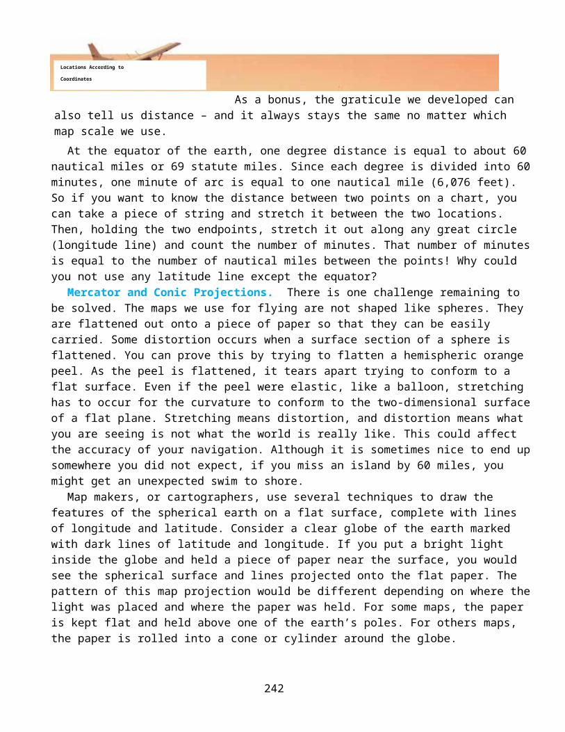
Mercator and Conic Projections. There is one challenge remaining to be solved. The maps we use for flying are not shaped like spheres. They are flattened out onto a piece of paper so that they can be easily carried. Some distortion occurs when a surface section of a sphere is flattened. You can prove this by trying to flatten a hemispheric orange peel. As the peel is flattened, it tears apart trying to conform to a flat surface. Even if the peel were elastic, like a balloon, stretching has to occur for the curvature to conform to the two-dimensional surface of a flat plane. Stretching means distortion, and distortion means what you are seeing is not what the world is really like. This could affect the accuracy of your navigation. Although it is sometimes nice to end up somewhere you did not expect, if you miss an island by 60 miles, you might get an unexpected swim to shore.
Map makers, or cartographers, use several techniques to draw the features of the spherical earth on a flat surface, complete with lines of longitude and latitude. Consider a clear globe of the earth marked with dark lines of latitude and longitude. If you put a bright light inside the globe and held a piece of paper near the surface, you would see the spherical surface and lines projected onto the flat paper. The pattern of this map projection would be different depending on where the light was placed and where the paper was held. For some maps, the paper is kept flat and held above one of the earth’s poles. For others maps, the paper is rolled into a cone or cylinder around the globe.
Mercator projections are most useful when the map only shows a very small part of the earth’s surface. The curvature of the earth is pretty small, so if you are very close to it the surface appears flat.
239
Chapter 9 - Flight Navigation
The Basic Schemes if Longitude and Latitude
Locations According to Coordinates
Examples
Degrees 360 per circle 23° N Minutes 60 per degree 23° 10’ N Seconds 60 per minute 23° 10’ 34” N

Each technique results in a different map projection. Notice the picture that shows the different projections and their names.
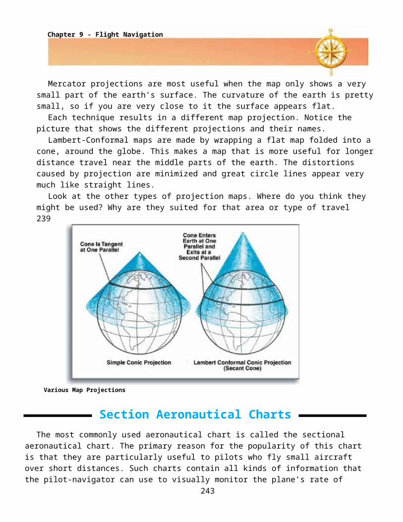
Lambert-Conformal maps are made by wrapping a flat map folded into a cone, around the globe. This makes a map that is more useful for longer distance travel near the middle parts of the earth. The distortions caused by projection are minimized and great circle lines appear very much like straight lines.
Look at the other types of projection maps. Where do you think they might be used? Why are they suited for that area or type of travel 239
Various Map Projections
Section Aeronautical Charts The most commonly used aeronautical chart is called the sectional aeronautical chart. The primary
reason for the popularity of this chart is that they are particularly useful to pilots who fly small aircraft over short distances. Such charts contain all kinds of information that the pilot-navigator can use to visually monitor the plane’s rate of progress and its position over the ground. In addition, the sectional presents that information necessary to basic radio navigation, which is the pilot’s electronic means of updating his position.
Sectionals are Lambert-conformal projections, and each one represents a relatively small portion of the earth’s surface. All sectional charts begin as blank sheets of paper and upon these are printed the data, in different colors, that cartographers have prepared. The charts show many symbols and include a legend, which explains most of the symbols and colors.
A person using a sectional could glance back and forth between the actual chart area and the legend area and do a fair, though time-consuming, job of reading the sectional. However, this is not the best way. It is better to study the symbols and colors until there is a feeling of seeing the earth’s surface in its real form. To help instill this feeling, cartographers try to make the basic chart look as much like the actual surface as possible. By necessity, they must superimpose other data. Some of these superimposed data are relief, hydrographic and cultural features.
240

Relief. Relief is the term used to describe elevations. Relief is depicted by color tints, contour lines, and shading. In the legend of each chart, a vertical, graduated scale shows different tints and the number of feet above sea level represented by each tint. Now, imagine that a green tint represents all the surface area that is between sea level and exactly 1,000 feet above sea level on the chart. This tint will follow the contour of the terrain; consequently, the border of the green tint will be very irregular, as if all the hills and mountains
240
had been sliced through horizontally at the 1,000-foot level. Since different color tints normally
represent 1,000-foot increments in elevation, the next color would represent a 1,000- to 2,000-foot-above-sea-level land elevation. Thus, the colors representing terrain elevation change for however many thousands of feet are depicted on the particular chart. The irregularity of their borders gives an indication of terrain roughness.Contour lines are used to show changes in elevation smaller than the 1,000-foot color-tint scheme. These contour lines join points of equal elevation. Elevations represented are printed on certain ones. Spacing of the contour lines shows whether the rise in elevation is gradual or abrupt; that is, a hill with a gradual slope would have widely spaced contour lines. A steep hill, like a volcanic cone, would have closely spaced contour lines. If a hill or mountain has a vertical cliff, its contour lines would come together at the location of the cliff. The highest point on a hill and the highest points within a group of hills or mountains are pinpointed by black dots, which have the exact elevation printed beside the dots.In the very hilly or mountainous areas, another technique is used to give the impression of relief. It is called pictorial presentation. With an airbrush, cartographic illustrators make the mountains look as if the sun were shining on them from an angle. The steeper the mountains, the darker the shadows will be on the opposite-the-sun sides.With the exception of marsh grass, vegetation that covers the terrain is not shown. You can see why, if you think of the many other colors and tints that would be required. An already cluttered chart would become even more difficult to read. Big trees and small trees also look very much the same from an altitude of several thousand feet, so vegetation is of little or no value as a visual navigational aid.Hydrographic Features. Water, on the other hand, is a very valuable navigational aid. Streams and lakes are depicted with the color blue. These water, or hydrographic, features are accurately drawn. As
241
Chapter 9 - Flight Navigation
Portion of Sectional Chart with Key to Selected Symbols
1. City2. Small Community3. Single Building4. Highways5. Railroads6. Radio Towers7. VOR Station8. Power Line9. Airport
241an example, every lake has a unique shape, and it is very easy to identify a lake by comparing its actual shape, as seen from the air, to the shape shown on the sectional chart on the previous page.
Cultural Features. The landscape has been marked by people. The pilot can easily see most of these changes from the air. These objects come under the general classification of cultural features. Where possible, cartographers duplicate the shapes of such cultural features.
If a city, or town, is large enough to have a distinguishable shape, it is printed in bright yellow with a thin, black-line border. Very small communities, consisting of a store or two and a few houses, are shown by a small black circle. In both cases, the name of the city, town or community is shown.
Significant cultural sites that would be visible from the air are usually indicated on sectionals. For instance, mines are charted as picks and sledgehammers. Highways are printed as black or magenta lines. Railroads look like lines with crossties and power lines look like lines with towers. In any case, the location is on the map and is accurate and visible.
Each obstruction is clearly identified on the sectional. There may be altitudes listed next to the symbols, if they meet certain height criteria. If an obstruction is between you and your destination, then you should know its height.
Airports
Locations of airports and data about them are among the more prominent symbols printed on sectional and other types of aeronautical charts. Most airports within the area covered by the sectional are shown.
There are many kinds and sizes of airports. Some are so small that their use is, by aircraft performance, restricted to small aircraft. Others are so large and involve so much air traffic that they are restricted to serving only those aircraft that possess special electronic equipment.
There are several ways of classifying airports, but the broadest classification identifies them as either civil airports or military and joint-use airports.
Civil Airports. Since the majority of airports are civil, they are a good starting point for discussion. If the airport is unpaved, a prominent magenta circle will show its location on the sectional. This means that a landing area is available and that it may consist of either a sod or graded runway. Near the airport symbol will be printed the name of the airport, its height above sea level and the length (in hundreds of feet) of its longest runway.
242
If the airport has facilities, four small projections, or ticks, radiate outward from the circle: one projection toward each compass direction. What is meant by facilities? Very simply, this means that the airport has more than just a runway available. It may have only aviation fuel available or it may have all kinds of facilities, including food, lodging and hangar space. To find out exactly what facilities are available, the pilot has to refer to a special publication such as the Airport/Facility Directory.
Many civil airports are privately owned. To distinguish these, a large R is shown within the circle and the abbreviation (Pvt) follows its name. If verified information about an airport has not been received but it serves as a landmark, its circular symbol will contain a U to indicate that it is unverified. Some closed airports, which have paved runways, are also good landmarks. They are shown as a circle with an X across the circle to let you know the runway may no longer be suitable for landing. 242
Airport Symbols on an Aeronautical Chart
Airports with paved runways 1,500 to 8,000 feet long are shown by either a magenta or blue disk. If the airport does not have an air traffic control tower, the disk is magenta. If it has a control tower, the disk is blue. The airport’s runway layout appears within the disk.
Those airports with one or more runways longer than 8,000 feet are printed as heavily outlined runways. The color of this outline also indicates whether or not the airport has a control tower. Seldom seen airport symbols like heliports, unpaved military airports and seaplane bases are shown on most sectional aeronautical charts.
243
Chapter 9 - Flight Navigation

The basic information pilots need in order to land at an unfamiliar airport is printed near the airport symbol. First will be the airport’s name, next will be the airport’s surface elevation above mean sea level, and then the length of its longest runway shown in hundreds of feet. Additional information about airports is contained in several FAA publications to give the aviator sufficient details to fly into and out of the airport.
Military and Joint-use Airports. Military airports are depicted in the same manner as civil airports. The only distinguishing feature is in the airport’s name: an abbreviation for the owning military service, such as AFB for Air Force Base, follows the name. Joint-use airports are found where civil aviation and military aviation share the runways. This does not mean that they will share the facilities.
243More than likely, the civil aviation passenger terminal and other facilities will be distinctly separated from the military operations.
How do pilots know (from the aeronautical chart) that an airport is the joint-use type? They will know from the name of the airport. The name of the military installation, such as Sheppard AFB/Wichita Falls, appears above the name of the civil airport.
Airspace and Airways
Years ago, when aviation was just beginning to be recognized as a useful tool of society, not many airplanes were around. The people who were pilots could fly anytime and anywhere. There was little danger of colliding with another airplane because so few were in the sky.
Today, things have changed. There are hundreds of thousands of airplanes in the United States alone, and the number is growing. The amount of flying these airplanes do and the airports where they converge make it necessary to setup rules and restrictions that govern the planes, the pilots who fly them and the airspace in which they fly. The Federal Aviation Administration (FAA) establishes and enforces these rules and restrictions within the USA.
Controlled Airspace. This is a general term for airspace that has several subdivisions and is shown on aeronautical charts. When an airplane is flying in or through controlled airspace, it is subject to control by FAA air traffic controllers. This controlled airspace has dimensions; some of it starts at surface level while other subdivisions begin and end at various altitudes.
The largest area of controlled airspace is called the continental control area. This subdivision generally starts at 14,500 feet above mean sea level, extends upward into space and covers the United States (excluding Alaska and Hawaii) like a blanket.
Most pilots have to fly into control zones because these control zones are around many airports. They begin at surface level and end at the base of the continental control area.
If there is an operating control tower at an airport, there will be an airport traffic area within the control zone. This is a special controlled airspace area in which aircraft are directed during takeoff and landing operations.
In many parts of the country, there is uncontrolled airspace, which starts at the surface and extends upward to the continental control area. There are also rules and restrictions for flying in uncontrolled airspace, but not as many as there are for controlled airspace.
Airways. Airways are three-dimensional highways in the sky and are another subdivision of controlled airspace. There are low-altitude airways and high-altitude airways for use by all aviation traffic.
244

Occasionally, special circumstances require the use of a specified airway. If this requirement is routine or known, then that information is provided in the supplemental FAA publications for the area.
Low-altitude airways are shown on the sectional chart. These are known as Victor airways and are based on the locations of radio navigation stations, which are called Very-High-Frequency Omnidirectional Radio Range (VOR). To follow these airways accurately requires the use of a special directional radio receiver.
Special-use Airspace. There are some special, but relatively small areas of the airspace that most pilots have to avoid. Therefore, it is part of the pilot’s duty to make sure the flight doesn’t include travel through such airspace. Prohibited airspace and restricted airspace are clearly marked on all types of aeronautical 244
charts. The legends of the charts include details on the airspace. Prohibited airspace means that a pilot must avoid it. Restricted airspace actually means that at certain times all aircraft flight within the area is prohibited.Warning and alert areas mean that pilots are expected to exercise extreme caution when flying through such areas. These areas are clearly marked on aeronautical charts as well.
A military operations area (MOA) is a special segment of the airspace where military flight-training activities are conducted. It is identified on aeronautical charts, but this does not necessarily prohibit other aircraft from using the same airspace. It is simply a notification to the civilian pilot that military aircraft may be in the area. These military aircraft usually fly very dynamic profiles, changing altitudes and airspeeds rapidly. This type of flying places the civilian aircraft in the MOA at a higher than normal risk for collisions.A military training route (MTR) is a sometimes-flown, low-level training route appearing on sectional aeronautical charts. The aircraft on such routes are practicing low-altitude flying and may not be aware of your position. Civil pilots should be familiar with the MTRs and can find this information on the sectional chart.
Other Types of Aeronautical Charts
There are a host of additional chart types available to the pilot. Each chart has an intended use or shows important information in a unique way. Terminal Area Charts, for instance, show extreme detail around airfields so that the pilot can study the takeoff and landing areas closely. High-altitude en route charts show less terrain feature information and more electronic navigation aid information. When aircraft are flown at high altitude, terrain features are less important to the pilot than the airway information, so it is reduced to make the chart cleaner.Finally, all aeronautical charts are updated rather frequently. Most of the sectionals are updated every 6 months, while others are updated once per year. The frequency of chart updates is controlled by pilot requirements and how often information changes. These updates help prevent accidents from happening, so they are very important to the FAA and the aviator.
Basic Navigation Principles The aeronautical charts previously discussed influence navigation. An outdated chart, for example, certainly can influence navigation to the point of making it unsafe. Weather is also a major factor in navigation. The list
245
Chapter 9 - Flight Navigation

could go on and on and would eventually pertain to everything involved with flight of the airplane. For this section, only the basic factors that must be considered by all pilots will be presented.
The True-course Line. It was mentioned earlier that a straight line drawn on a sectional aeronautical chart approximates a great-circle route. There are times, however, when the shortest distance is not the best. If the navigator intends to use radio navigation, it might be necessary to draw a series of straight lines between the origin airport, the radio navigation stations to be used and the destination airport. Another situation could involve flight around a high mountain or around prohibited airspace.
245It doesn’t matter whether there is a single line or a series of lines since the true course is what the navigator indicates as the course the airplane will follow. Why are such lines called true-course lines? It is because they are indications of direction with regard to true north.
True north is the location of earth’s north geographic pole. All lines of longitude converge at the North Pole. Each line of longitude on the sectional shows the direction of true north with regard to any location on the chart because it is drawn through the pole.
Charts are printed so that the top is north. One can measure true direction from a line of longitude. Where a true-course line crosses a line of longitude, a point is formed. The direction in degrees is measured clockwise from the line of longitude to the true-course line. Of course, the navigator knows whether the direction of travel is east or west, but if it were west, the direction would continue clockwise until the second interception of the true-course line.
Magnetic Courses. Generally, the direction of magnetic north is different from true north. This is because the magnetic poles, north and south, are not in the same place as the geographic poles. Also, the magnetic lines of force do not form straight north-south lines, as do the imaginary lines of longitude. The magnetic north-south lines of force weave back and forth a little much like lines of contour. They show where the earth’s magnetic field is the same, not the direction to the magnetic pole.
These lines are shown on the sectional chart as rather dark dashed lines and are printed in a reddish color (magenta), usually running in a north-south direction. The lines are broken intermittently to show the number of degrees difference (east or west) between true north and magnetic north where the line is located. These lines are called isogonic lines because they connect the points where the angle between magnetic north and true north is equal. Across this sectional chart, for example, the difference in direction between magnetic north and true north from one side of the chart to the other is 9 degrees, 30 minutes. This was as of 1988. The next issue of this particular chart may show a greater or
246
True Course as Measured from True North

lesser variation because magnetic lines of force change periodically as the earth’s surface shifts and the core moves around.
The magnetic compass points toward magnetic north; it has no idea of true north’s location. The pilot, therefore, must steer according to the direction or heading shown by the magnetic compass. Since there almost always is a difference between magnetic north and true north, this difference (in degrees east or
246
west) must be subtracted from or added to the true-course direction. Otherwise, the airplane will not follow the true course drawn on the chart.
Compass Deviation. Although the magnetic compass is the most reliable indicator of direction, it is a mechanical device and no mechanical device is perfect. The compass must be adjusted against a known standard that is correct.
Installing the magnetic compass in an airplane causes other influences to come into play. Most metals and electrical power will cause a compass needle to deviate from magnetic north. This means that the compass must again be adjusted once it is installed in the airplane. The deviations caused by electrical power and metal are entered on a compass correction card and kept in the aircraft for reference if the pilot chooses to fly by the magnetic compass.
Altimeter. The altimeter usually is thought of as a flight instrument; however, it is also a factor in navigation. The altimeter is the only non-electronic means the pilot has of determining the airplane’s distance above the surface. Since heights of cultural and natural surface features are shown on aeronautical charts in feet above mean sea level, the correctly adjusted altimeter is the means of determining safe flight clearance above obstructions. The altimeter also plays a significant role in the determination of the next factor, true airspeed.
True Airspeed vs. Ground Speed. True airspeed is useful to the pilot because it is a measure of how fast the airplane is flying through the air. The air changes with altitude and temperature, right? Yes, it does. However, the instruments in the aircraft measure flight through air, not across the ground.
Ground speed is a measure of how fast your aircraft is going across the surface of the earth. If the relative wind were behind you, your ground speed would be higher than your true airspeed because you are getting a push along. Your true airspeed would not change because it measures what is happening to you in the air mass. The air mass is moving along with the wind, so you don’t see it affect the true airspeed. Ground speed is important to the pilot because it determines how long it will take to get from a start point to the destination, not coincidentally, measured across the ground.
Wind and the Wind Triangle. The effect of wind upon an airplane in flight can either increase or decrease ground speed depending on whether the airplane is flying with or against the wind. This effect is rather easy to determine. All one needs to know is how fast the wind is blowing and whether the flight is with or against the wind. Flying with the wind requires adding the wind speed to the true airspeed, and flying against the wind requires subtracting the wind speed from the true airspeed.
The situation changes when the airplane’s flight path is at an angle to the wind. What happens is that the airplane does not follow the course drawn on the aeronautical chart. This is because the wind tends to make the airplane travel along with it at the same direction and speed. This effect of the wind is called drift.
247
Chapter 9 - Flight Navigation

The only way to correct such a situation is for the pilot to fly a heading that will compensate for the amount of drift caused by the wind. In flight, this can be done by trial and error until a heading is arrived that will keep the airplane on the intended course line.
A better way to combat wind drift is to determine the heading that will be needed well before departure. In fact, this is a task of preflight navigational planning and it isn’t difficult to do.
The figure on the next page shows a wind triangle, a tool used by the pilot to figure out where wind drift will cause the aircraft to fly over the ground. It can also be used to counter the effect of drift. The grid shown is oriented to true north. The line pointing off of the aircraft’s nose is the true course from A to B.
247
The wind line blows the aircraft off course and results in an actual track across the ground labeled as the ground track.So what would you do if you wanted to correct for the wind drift? Fly into the wind. Since we fly
direction using aircraft heading, we need to know how many degrees to steer into the wind. This is found by measuring the number of degrees between the true course line and the ground track. Then, steer that many degrees into the wind. Simple!
Using a Wind Triangle
There are several tools that help the pilot figure out drift corrections. Flight plotters are aviation specific protractors that make determining angles and headings quick and painless. Flight computers come in many
248

varieties. They may be little more than circular slide rules (find an old guy and ask him what a slide rule is) or as complex as hand-held computers that can rapidly calculate flight information.
Navigation Techniques
The two basic techniques of air navigation are pilotage and dead reckoning. One or the other of these has been used since cross-country flights were first possible.
Pilotage. Pilotage means navigating by reference to visible landmarks. It can be as basic as flying above and following a highway or railroad to the destination. If a pilot is totally familiar with the geographic area of the flight and has flown the route many times before, references to landmarks may not be necessary.
248On the other hand, it might be necessary to use a sectional chart as backup for an area that is not quite
so familiar.Use of the pilotage navigational technique in completely unfamiliar territory requires more caution and
preparation. This preparation may involve the following steps: (1) A true-course (TC) line is drawn on the aeronautical chart from the point of departure to the
destination. (2) Using the scale printed on the chart, or a flight plotter, the total distance to be flown is measured
and the TC line marked off in segments of 10 miles each. These distance segments help the pilot or navigator locate landmarks and determine the progress of the flight over unfamiliar territory.
(3) Landmarks are selected along or very near to the TC. The landmarks along the TC are used as checkpoints, with the word checkpoint meaning the place over which the airplane should be at a certain predetermined time. It is also good practice to select a checkpoint at the end of the destination so that the pilot will know immediately if the airport has been overflown.
(4) “Brackets” on each side of the course should be selected. Brackets are easy-to-see surface features to either side of the TC; they are used between checkpoints to help maintain the proper course over the ground. If you are very unfamiliar with the area, choose easily recognized features like large cities or mountains.
Pilotage can involve extensive planning. It was presented earlier how wind affects the airplane’s rate of progress and direction over the ground. With other navigational methods, this is considered and calculated prior to beginning the flight. Pilotage, on the other hand, involves observing how much drift to the right or left of the TC the wind is causing and compensating for the drift by changing the heading of the airplane. It is a basic, “eyeballs out” method of navigation that is an essential skill.
249
Chapter 9 - Flight Navigation

Navigation by pilotage,
then, can vary from doing considerable planning to no planning. When flights are of short distances over familiar territory, most pilots simply preflight their airplanes and go.
Dead Reckoning. Dead reckoning is the basis for professional-level navigation. While pilotage is an “eyeballs out” form of flying from one place to another, the dead-reckoning technique involves the systematic consideration of all factors that will and could affect the flight. These factors are considered in the proper sequence, calculated, recorded or logged
249
where appropriate, and updated as the flight progresses.The term dead reckoning originated with the mariners of long ago. These ship navigators deduced their
positions at any given time by using distances and directions that their ships had sailed since passing or leaving a known position. Such positions were determined at frequent intervals and were entered in the ship’s logbook under a column headed by the abbreviation “ded.pos.” for deduced position. The reckoning (counting up or figuring) necessary to obtain these entries was known as “ded. reckoning,” which later became dead reckoning. Since the task of the nautical navigator is to know the position of the ship at any given time, the air navigator using dead-reckoning navigation should know the position of the airplane at any given time.
By measuring and calculating, by keeping account of navigational factors, by using a flight plan and by properly using the basic navigational instruments, it is possible to fly directly to any place in the world. Essentially, this is what happens during present-day long-distance flights. However, dead reckoning today is backed up by various electronic aids.
250
Flight Plotter
Let us bring together the basic factors bearing upon air navigation. We will do this by constructing a cross-country flight plan according to dead-reckoning navigation. What we are about to do is no more difficult than knowing which direction to go to the grocery store, what turns to make and how long it takes between turns.
Our flight will be from Phillipsburg Airport at Phillipsburg, Kansas, to Oakley Airport at Oakley, Kansas. The distance is 78.5 nautical miles, which you could measure with a plotter or a string. A quick look at the “39” near Oakley on the chart tells us in order to clear the highest known feature within the area of the intended flight path by 500 feet, we will need to fly at least 3,900 feet above mean sea level (MSL). However, we will use 6,500 feet MSL as our cruising altitude, so any unknown obstructions should be no problem.
To keep track of our calculations, we will use a pilot’s planning chart like the one below. There are many types of planning charts. Some are standardized to provide aviators with a planning tool that is the same all across the United States. Some are customized to provide the pilot with quick look information first, then details as required.
Now we are ready to step through our basic planning process to make a dead reckoning flight plan. Work from the figure below as the steps are described.
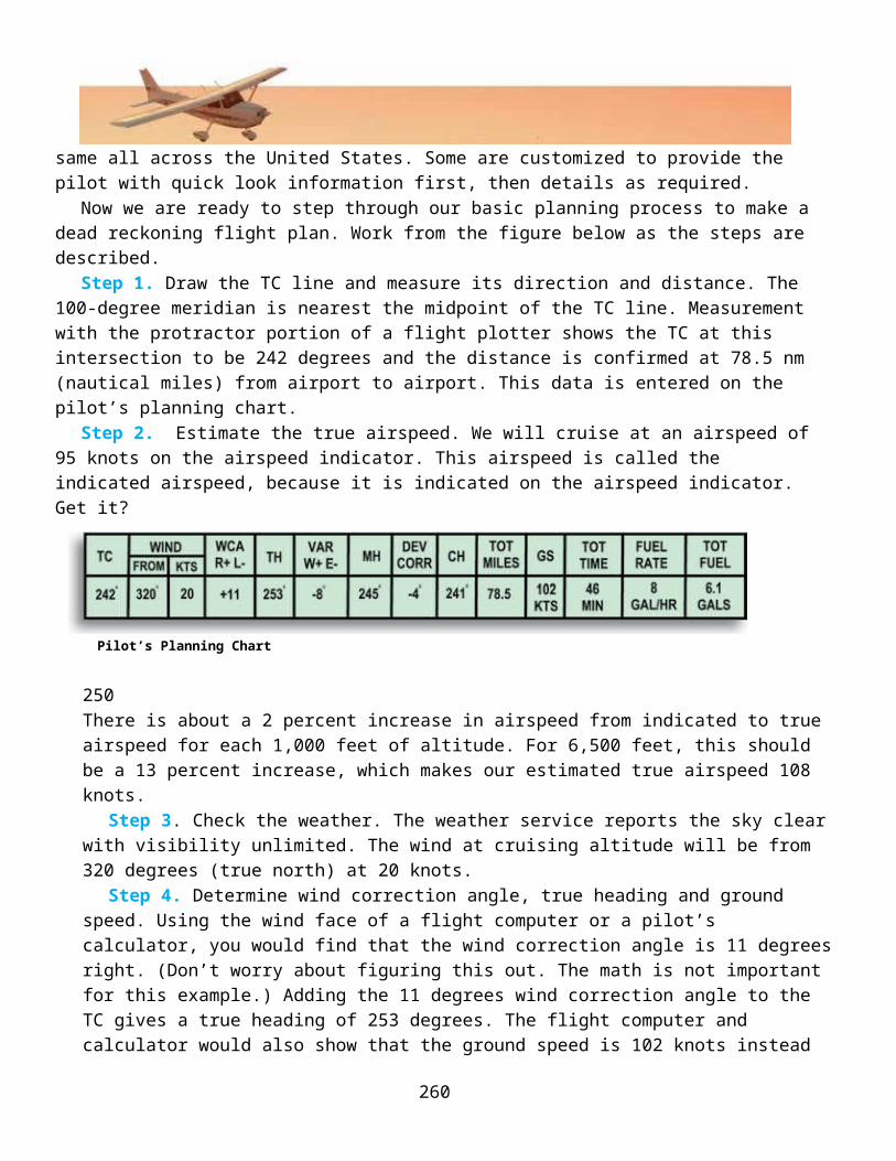
Step 1. Draw the TC line and measure its direction and distance. The 100-degree meridian is nearest the midpoint of the TC line. Measurement with the protractor portion of a flight plotter shows the TC at this intersection to be 242 degrees and the distance is confirmed at 78.5 nm (nautical miles) from airport to airport. This data is entered on the pilot’s planning chart.
Step 2. Estimate the true airspeed. We will cruise at an airspeed of 95 knots on the airspeed indicator. This airspeed is called the indicated airspeed, because it is indicated on the airspeed indicator. Get it?
Pilot’s Planning Chart
250There is about a 2 percent increase in airspeed from indicated to true airspeed for each 1,000 feet of altitude. For 6,500 feet, this should be a 13 percent increase, which makes our estimated true airspeed 108 knots.
Step 3. Check the weather. The weather service reports the sky clear with visibility unlimited. The wind at cruising altitude will be from 320 degrees (true north) at 20 knots.
Step 4. Determine wind correction angle, true heading and ground speed. Using the wind face of a flight computer or a pilot’s calculator, you would find that the wind correction angle is 11 degrees right. (Don’t worry about figuring this out. The math is not important for this example.) Adding the 11 degrees wind correction angle to the TC gives a true heading of 253 degrees. The flight computer and calculator would also show that the ground speed is 102 knots instead of the 108 knots estimated for true airspeed. That should make sense. The wind is blowing in our face, so we should be slowed down a bit. The wind correction angle, true heading and ground speed are entered on the pilot’s planning chart.
251
Chapter 9 - Flight Navigation

Step 5. Determine magnetic variation and magnetic heading. Looking at the isogonic lines on the chart reveals that magnetic variation is 8 degrees E near the middle of our route. We will consider this to be the average variation, so 8 degrees E must be subtracted from the true heading. This leaves a magnetic heading of 245 degrees.
Step 6. Determine the compass heading. It requires checking the compass deviation card in the airplane. Let’s say that we find it to be -5 degrees. This leaves a compass heading of 240 degrees. Following this compass heading should keep the airplane’s ground track on the planned TC.
True Course from Phillipsburg Airport to Oakley Airport
251
Step 7. Determine the time en route. We know that the distance is 78.5 nm and that the ground speed should be 102 knots (nautical miles per hour). A little math magic would tell us:
That’s about 46 minutes of flight time. Total time would take slightly longer because we have not counted the additional time required for takeoff and landing maneuvers.
Step 8. Determine fuel usage. This airplane burns 8 gallons of fuel per hour. A flight computer, or some more math magic, tells us that for 46 minutes of flight time, we will use 6.1 gallons of fuel.
Step 9. Select checkpoints. Checkpoints are selected according to the pilot’s or navigator’s choice. For example, the TC line crosses a distinct bend in the highway/railroad system that is 6.5 nm out from Phillipsburg Airport. Much farther along the TC there is another very good checkpoint east of Tasco — a
252

lake, a
highway, a railroad and a stream with a U bend in it. Again, the selection of checkpoints is an individual’s choice, but make certain you choose something you’ll be able to identify from the air.
Step 10. File a flight plan. It is always good sense to file a flight plan with the nearest FAA flight service station. This is done by telephone, computer or radio, and its primary purpose is to have a record of where the flight will be going and when it will be completed. If the flight isn’t completed and the flight plan is still open with the FAA, a search for the missing craft can be started within a very short time. Think of it like leaving a note with your mother. Mother likes to know where you are.
As you probably have already concluded, the preparing of a dead-reckoning navigational flight plan can be approached in different ways, or it can be put together differently from the example we have given. The sequence of the steps isn’t too important. The important thing is that all factors bearing on the flight be considered. So, filing the flight plan is always the last step in beginning such a flight, and closing the flight plan is the first step in concluding the flight.
The world of aviation has numerous aids to navigation. Some of these aids have become essential; that is, many flights into highly controlled airspace or through certain weather conditions would be either unlawful or impossible without modern navigational aids. Electronic developments or refinements are the basis for most of these in-flight aids to air navigation.
Electronics have also allowed the development or improvement of complete navigational systems. A navigational system, according to our definition, can provide accurate navigational information without depending on any other system or technique.
Electronic Aids In this section, we will acquaint you with a number of navigational aids. From the coverage provided,
you should be able to understand how and when such aids supplement dead-reckoning navigation.The Aircraft Radio. The aircraft radio is an aid to navigation because it is the pilot’s communication’s
link with FAA personnel and others who have an interest in the progress and termination of a cross-country navigational flight. The picture on the next page shows what a typical aircraft radio looks like. Its main working parts are encased behind the instrument panel, and the antenna, which transmits and receives signals protrudes from somewhere along the airframe, usually the fuselage or vertical stabilizer. The microphone contains a button that is depressed when transmitting and is popularly known as a
252
253
Chapter 9 - Flight Navigation
push-to-talk button. In small airplanes, the radio speaker usually is located somewhere in the overhead roof of the cockpit, but it can be anywhere. Most aircraft also provide the aircrew a place to plug in headphones so that aircraft noise can be reduced while listening to the radio. Military fighter aircraft have the microphone and headset inside the pilot’s helmet so that he can keep his hands free to employ weapon systems while talking to his wingmen.
Radios transmit voice communications over certain frequencies. These frequencies are assigned to different FAA regions and airfields, and allow you to talk specifically to a single controller. As you fly from one region to another, the controller has you change frequencies to talk to the next region. This organized way of handing you from one controller to the next allows the controller to concentrate on your safety while in his or her area.
Where do you find out which frequency to use? A current aeronautical chart will show some frequencies such as those to contact an FAA flight service station or an airport’s control tower. Such frequencies are changed from time to time for one reason or another, so all that plan a navigational flight are cautioned to double-check the frequencies printed using other FAA publications.
Two other controls found on the aircraft radio are the volume and squelch. The volume control’s purpose is obvious, but the squelch control serves to reduce background noise. This control decreases the sensitivity of the reception getting through to the radio’s speaker. This allows only the stronger voice signal to come through. When the voice signal you want to listen to is weak, however, it might be necessary to put up with a certain amount of background noise to make sure you do not miss a radio call meant for you.
Aviation is very dependent on radio communications and such communications have to be as brief as possible. Airplanes taking off and landing at a busy airport leave little time for extended conversations between the aircraft controller and the pilots. It is the controller’s job to space the airplanes so there will be
253
254
COM/NAV Radio and Microphone

a safe distance between them. The controller, therefore, must give pilots clear instructions in the shortest possible time. The pilots must reply in the same manner when they give information to the controller.Over a period of time, there has developed what we might call a spoken shorthand, that is used for
aircraft radio communications. Key phrases are used to ensure that the pilot has understood directions from the controller and will comply with those directions. The shorthand communication helps keep the airwaves clear for emergency messages or critical commands.
The Very-High-Frequency Omnidirectional Radio Range (VOR) Receiver. The VOR receiver is the second half of the aircraft radio. The two are separate operating units, but electronic firms usually build a unit that contains both types of receivers. In addition to the receiver, there is a VOR course deviation indicator situated elsewhere on the aircraft’s control panel.
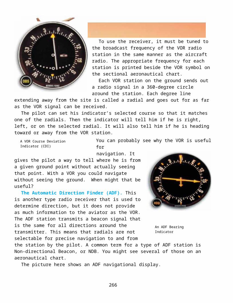
To use the receiver, it must be tuned to the broadcast frequency of the VOR radio station in the same manner as the aircraft radio. The appropriate frequency for each station is printed beside the VOR symbol on the sectional aeronautical chart.
Each VOR station on the ground sends out a radio signal in a 360-degree circle around the station. Each degree line extending away from the site is called a radial and goes out for as far as the VOR signal can be received.
The pilot can set his indicator’s selected course so that it matches one of the radials. Then the indicator will tell him if he is right, left, or on the selected radial. It will also tell him if he is heading toward or away from the VOR station.
You can probably see why the VOR is useful for navigation. It gives the
pilot a way to tell where he is from a given ground point without actually seeing that point. With a VOR you could navigate without seeing the ground. When might that be useful?
The Automatic Direction Finder (ADF). This is another type radio receiver that is used to determine direction, but it does not provide as much information to the aviator as the VOR. The ADF station transmits a beacon signal that is the same for all directions around the transmitter. This means that radials are not selectable for precise navigation to and from the station by the pilot. A common term for a type of ADF station is Non-directional Beacon, or NDB. You might see several of those on an aeronautical chart.
The picture here shows an ADF navigational display.
254
255
Chapter 9 - Flight Navigation
A VOR Course Deviation Indicator (CDI)
An ADF Bearing Indicator

The needle on the ADF receiver’s navigational display
Radials Broadcast by a VOR Station
points toward the station to which the receiver is tuned. Therefore, all the pilot has to do is align the nose of the airplane with the needle and flight will then be toward the broadcasting station.
There are several problems with the use of the ADF as compared to the VOR. The ADF display does not compensate for the effect of wind. The airplane might follow a curved instead of a straight course to the station, if the pilot does not manually turn into the wind to avoid drift. Signals in the frequency range used by the ADF will give incorrect directional information to the ADF receiver occasionally because they bounce off of land features much like an echo.
With all of its drawbacks, the ADF system is a useful aid to navigation. It still provides some directional information to pilots, helping them if they cannot see the ground. It just requires more work by the pilot to fly precise routes between points.
Distance-Measuring Equipment (DME). Many of the VOR stations across the country have a special unit called tactical air navigation (TACAN). When this unit is installed with a VOR, the station is called a VORTAC.
The TACAN portion will respond with a broadcast signal when it receives a signal from the DME unit in the airplane. The DME sends a signal and measures the time it takes to go from the aircraft to the VORTAC and return. The DME unit converts the time to nautical miles distance between the airplane and the station.
The VOR receiver is tuned to the same VORTAC as the DME unit. The VOR shows which radial the airplane is on and whether the flight is to or from the station. The DME tells how far away the airplane is at any given moment. So now, the pilot not only knows which direction he is from a ground station, like an ADF, but can plan to fly on a particular radial and knows how far it is to the station.
256

255This gives the aviator enough information to precisely define where he is, using only one electronic navigation aid.
There is one minor error associated with DME. It measures line-of-sight distance between the airplane and the VORTAC station. This means that it does not measure the horizontal distance between the airplane and the station because the airplane is at an altitude above the surface. This error is not of great significance, but you can see that the DME on an airplane flying at 30,000 feet and passing over a VORTAC station would show the airplane to be about 5 NM from the station, straight up.
Weather and Ground Radar. Radar, as you probably know, works on the principle of reflected radio energy. Its transmitter sends out a narrow beam of super-high-frequency radio energy. Some of this energy is bounced back to the radar unit’s receiver and is shown as bright spots and areas on a cathode-ray tube. This tube is known as the radar scope.
This can be useful to the navigator because radar can see very far, through the darkness, and through some weather. Small, radar reflective points on the ground can be listed on an aeronautical chart and used to identify your position very accurately.
Weather radar shows areas of precipitation, but its most important function is to show storm cells (thunderstorms) ahead. This allows the pilot or navigator to change course and to avoid those places that might be dangerous to flight.
Radar units can be very simple or very complex. Simple units might just show what is ahead of the aircraft so that the pilot can adjust the flight route. Complex systems provide color displays that tell you the intensity of weather, allow pilot designation of ground targets and are integrated with other navigation systems and helps update errors in those devices.
Radar gives the aviator one more tool to navigate better. It helps the pilot see far away and plan for route changes. As en route navigation becomes more complex for the pilot, any and all tools are appreciated.
Navigation Systems The VOR System. We have touched on the VOR system during previous discussions. Recall our
mention of VOR stations in the description of airways. We also mentioned VOR and VORTAC stations in the descriptions of the VOR receiver and DME. The total VOR system includes the airplane receivers and the ground stations working together to help the pilot navigate.
A modern VOR or VORTAC station is easily identified visually from the air or the ground. Inside the station, two radio signals are created and broadcast. One is stationary and produces a constant, unchanging outpouring of signals in all (omni) directions. The other signal is broadcast by a directional antenna that rotates at 1,800 revolutions per minute.
When the VOR station is placed in operation, it is adjusted so that the stationary signal and rotational signal are lined up in the exact direction of magnetic north for the location. The aircraft receiver measures the difference that develops between the two signals as the rotational signal spins around. The difference is then converted to radial information so that the pilot can select a specific navigation route.
Although the signals from VOR and VORTAC systems are line-of-sight signals and can be stopped by the terrain (such as a mountain) that lies between the station and an airplane, it is difficult to be out of range
257
Chapter 9 - Flight Navigation

of at least one station on any flight. Therefore, it is possible to pick out a line of VOR/VORTAC 256
VORTAC Station
stations between an origin and a destination, and use them for a cross-country navigational flight. The pilot only has to tune in to one station and fly to and from the station, until within radio range of the next station. Within range of the next station, the to-from process is repeated, and so the flight proceeds.
Another very useful and important feature of the VOR system is that of providing a position fix. Obtaining a position fix is exceptionally easy when the airplane is equipped with two VOR receivers (as many are). The receivers are tuned to different stations and their course indicators are rotated until FROM readings are obtained and the CDI needles are centered. This procedure gives the radial from each station on which the airplane is located at the moment. Lines drawn on the sectional chart extending from the two VOR radials will cross. The point at which these lines cross shows the position of the airplane at the time the radials were taken.
Long-range Navigation (LORAN). LORAN is an acronym for long-range navigation. It is a complete navigational system, and its basic form has been in existence for many years. LORAN is used by large cargo ships and many small, privately owned seaworthy craft. It is also used by aircraft as a means of navigation.
Several modifications to improve LORAN have caused it to be identified as A, B, C and D. LORAN-C is what we might call the most popular model. The system uses, at any one time, at least three ground based radio stations, a receiving unit aboard the aircraft and special LORAN navigational charts.
The ground-based radio stations are located many miles apart and are known as master and slave stations. The master station automatically broadcasts signals that, when received by the slave stations, cause the slave stations to also automatically broadcast delayed, responding signals. 257
258
Radio waves travel at a virtually constant speed. Thus, from the time a radio signal takes to travel between two points, distance can be determined.
An airplane’s LORAN unit receives the signal transmitted by the master and slave stations. It then displays the time difference (in microseconds) between receiving the different signals. By using the time differences shown, the airplane’s position can be plotted on the LORAN navigational chart.
LORAN navigational charts show the time differences of signals received from master and slave stations as lines of position. These time differences appear on the chart as curved lines. By finding the curved line for the time difference received, the pilot or navigator knows that the aircraft’s position is somewhere over the territory covered by that specific thin line. To find the aircraft’s exact position, the time difference of signals from a second slave station is measured. Where the curved line from the second set of signals crosses the first on the LORAN chart is the aircraft’s position.
The LORAN-C receiving unit can be set for automatic operation, and it can be coupled with automatic navigational computers. In the automatic operation mode, it displays time difference continuously. When coupled with an automatic navigational computer, the aircraft’s geographic coordinates are converted from the time difference and displayed. This makes it a bit easier to plot your position on a regular aeronautical chart.
LORAN is an excellent means of navigation, but a newer system has been developed that offers a high degree of accuracy worldwide. It is called the global positioning system or GPS. As this new system becomes less expensive to install in aircraft, LORAN use may decrease and may even stop being used altogether.
The Global Positioning System (GPS). The GPS navigation system consists of roughly 30 satellites in orbit around the Earth, several ground tracking stations and a receiver in the aircraft. The total number of satellites varies as some are repaired and upgraded. The ground control sites watch where the satellites are in orbit and continually correct their reported location and time-of-day signals. This is done so that when the satellite communicates with your receiver, it gives the best possible position it can to help navigate.
The GPS receiver converts the signals coming from the satellites into position coordinates. It can give the pilot his latitude, longitude, elevation and current time, if the receiver can see any four of the 30 satellites.
259
Chapter 9 - Flight Navigation
GPS Receiver
258
The Segments of a Global Positioning System
GPS satellites were controlled by the US Department of Defense at the time of this writing. Because position accuracy is very important to military operations, GPS accuracy is very good. However, that “good” signal is encoded so that only US forces can use it, which helps keep the enemy from using it against the US military. The usefulness of GPS for the civilian community demanded that they have the ability to receive its position data as well. Therefore, the GPS satellites send out two signals for position data.
The Precise Positioning System (PPS) is the military’s encoded signal. Its accuracy is classified, but public literature suggests position location within about 30 meters. The Standard Positioning System (SPS) is the civilian public’s signal and its accuracy is controlled by a program called Selective Availability (SA). During times of peace, SA degradation of the SPS signal is not necessary and SPS
260

accuracy is near that of PPS. However, in time of crisis, SA can be returned to service degrading, or even denying, SPS service to any region and even the entire globe, if necessary.
GPS accuracy can be greatly improved at a specific location using a technique called differential GPS. If a ground GPS station is setup and its latitude, longitude and elevation is very precisely measured, it can send out a correction signal to nearby aircraft using GPS. This signal fixes the little errors in the satellite signal and makes the received position very accurate. Why might you need such an accurate signal? 259Inertial Navigation. The inertial navigational system is a little different than the others we have
discussed. It is a self-contained unit located within the aircraft that needs only to be programmed for a starting point and destination. The unit does, however, need electrical power to keep its parts functioning. An inertial navigational system does not measure airspeed or wind velocity. It does not actually measure anything except movement. This movement is translated into speed, direction and distance. Movement is detected with a very sensitive device called an accelerometer.
Accelerometers function somewhat like a pendulum. The amount a suspended pendulum will be moved depends upon the change in movement of the body to which it is attached. If a pendulum is attached to a string and suspended in an airplane that is maintaining a constant speed, the pendulum will remain motionless. Slow the airplane and the pendulum will swing forward; speed the airplane up and the pendulum will swing backward.
The real accelerometer could be a spring-loaded mass in a container that allows the mass to move in a single linear direction (forward and back). The springs serve to center the mass when an inertial force is not acting upon it.
Accelerometers mounted on a platform and set 90 degrees to each other could sense left-right, forward-backward and up-down motions. These motions are watched by an integrator and sent to a guidance system computer. Sounds futuristic, doesn’t it? The computer really does no more than keep track of where the airplane is, based on where it started and what motions have happened since it was turned on.
INS accuracy does get worse over time. Most systems drift by about ½ NM per hour. The good news is that inertial systems are usually integrated with the other systems on the aircraft. These systems can update the INS with known ground point positions. For instance, the radar could pinpoint a landmark and tell the INS exactly where it is. GPS can also update the INS and keep it accurate to either the PPS or SPS limits. Finally, if you see a landmark and know its coordinates, you can fly over it and do a visual update to the INS.
The Area Navigation System (RNAV). We might say that the heart of the area navigation system (RNAV) is a computer. That’s because RNAV is really more of a computer controlled navigation system than a set of stations and receivers. This system uses VOR-type radio stations or GPS as reference points, but allows the pilot or navigator to fly directly from the airport of origin to the destination airport without following the airways. It is possible to use this system and fly very long distances without passing over a single VOR station. This might be very useful if you desire to fly a long great circle course and save time and fuel en route.
The RNAV computer takes your desired straight path between start point and destination, then looks to see how that path flies past the VOR stations. It monitors your real flight path and tells you when you are getting off course by comparing its predicted position from the VOR and its actual position. GPS flown RNAV uses GPS position backed up by either INS or ground station signals. The FAA has some rules on when and how GPS can be used for RNAV and publishes them in their flying publications.
261
Chapter 9 - Flight Navigation

260
Landing Navigation Systems
The area navigation systems covered thus far are fine for getting around the countryside, but do not have the position accuracy necessary to get a pilot on to a 50-foot wide runway. That requires a special navigation system that is highly accurate within a limited range. These landing systems fall into two categories: precision and non-precision. Precision landing systems can get a pilot very close to the end of the runway, and in some cases even land the aircraft using its autopilot. Non-precision landing systems get the pilot very close to the runway so that when they get below the weather, they can easily see the airfield and land.
The Instrument Landing System. The Instrument Landing System (ILS) is used only within a short distance from the airport and only when the purpose is to land the airplane. During clear weather, it is not necessary to use an ILS because the pilot can see the airport and runway. Let there be low clouds, rain, snow or other visibility-reducing conditions and the ILS is essential.
The figure below includes the arrangement of the ground-based components of an ILS system. Briefly, what the ground-based system does is to broadcast very precise directional signals. These signals provide a lateral and vertical path to the runway. The lateral (centerline) and vertical (glide slope) signals are usable within 18 NM of the runway.
All ILS systems broadcast marker beacons. These are directed upward within a relatively narrow
Ground-based Components and Instrument Indications of an Instrument Landing System (ILS).
262

261
space, and they serve as checkpoints to tell the pilot the airplane’s position. Some ILS systems have three marker beacons: the outer, the middle and the inner. However, only two such beacons are found at most airports—the outer and the middle. Marker beacons generally tell the pilot that they are at an important place along the approach. For instance, a marker might indicate that the aircraft should have its gear down, or that it is time to decide if you can see the runway to land or need to go-around and try another approach.
Equipment in the airplane to use the ILS consists of a glide-slope receiver and a marker-beacon receiver. Glide-slope and azimuth information are displayed on a VOR course indicator. This course indicator (also called navigation indicator) has a localizer needle (vertical) and a glide-slope needle (horizontal). The localizer needle operates in the same manner as when its receiver is tuned to a VOR station. For the ILS, it shows the pilot whether the airplane is right or left of the centerline. The glide-slope needle shows whether the airplane is above or below the glide slope. By proper manipulation of the airplane’s flight and power controls, the pilot can keep the craft on a perfect flight path to visual contact with the runway.
The marker-beacon receiver has a light display for showing passage over each marker beacon. Passage over the outer marker causes a blue light to flash; passage over the middle marker is indicated by the flash of an amber light; and, if an inner marker is present, a white light flashes upon overflight. As the airplane crosses each marker beacon, a tone is also heard over the radio speaker if this feature is selected on the intercom panel.
Use of the ILS requires that the pilot locate the system. The standard way this is done is through the combined efforts of the pilot and the FAA air traffic controller. The FAA controller directs the pilot toward an intercept of the intended ILS using his area radar. In the meantime, the pilot has tuned one of the navigational receivers to the ILS frequency. Upon intercept of the ILS, communications are established with the airport control tower for landing.
There is much more to using the ILS than we have stated here, and it isn’t as simple as it seems. If you can imagine trying to follow the directions shown by the ILS while doing the tasks required of precision flying and at the same time communicating with airport control tower personnel, you get more of an idea of its complexity.
Microwave Landing System (MLS). In Europe, the microwave landing system is replacing the instrument landing system discussed above. The advantages to all of aviation are many, but the primary advantage is that the MLS is more efficient than the ILS.
Where the ILS produces narrow beams for guidance to the runway, the MLS broadcasts much wider beams—both horizontally and vertically. In fact, the MLS can create an electronic funnel that spreads horizontally as much as 120 degrees and vertically as much as 20 degrees. You can imagine how much of the airspace is covered by this electronic funnel just a few miles from the runway. This wide-mouthed funnel is easy to enter because the intercept can be made from any angle and from any distance within range of the system.
262
263
Chapter 9 - Flight Navigation
Course Deviation and Glide Slope Indicator

The MLS also has a precision back-course guidance that can help pilots continue to navigate as they go-around from a poor approach. This guidance provides the pilot reassurance as he reenters the weather and can no longer see the airport.
Differential GPS Landing Systems. So, what could a very accurate GPS guidance system be used for by the pilot? How about highly accurate landings? Because GPS signals are not transmitted in any particular direction, precision approaches can include curved paths and tiered altitudes. In fact, a GPS approach can take virtually any shape, as it is computer generated.
Approaches have always been a point of discussion with the communities that surround airfields. Noise and other environmental concerns affect the people in the airport community. GPS approaches can be molded to the community’s needs and still satisfy the aviator. That is the goal of any good navigation system.
263
264
A Safe Landing

nG
lobal Coordinate System grid system (graticule) great circles and small circles latitude and longitude prime meridian hemisphere mercator and conic projections sectionals relief and contour lines
hydrographic and cultural features civil, military, and joint-use airports
n controlled airspace airways special-use airspace true course vs. magnetic course compass deviation true airspeed vs. ground speed wind and the wind triangle pilotage dead reckoning
aircraft radion FAAn VOR and TACAN Receiver (VORTAC)
radial Automatic Direction Finder (ADF) Distance Measuring Equipment (DME) weather and ground radar Long-Range Navigation (LORAN) Global Positioning System (GPS) Inertial Navigation System (INS) Area Navigation System (RNAV) Instrument Landing System (ILS) Microwave Landing System (MLS) Differential GPS Landing System
265
Chapter 9 - Flight Navigation
FILL IN THE BLANKS
1. A grid may be made to provide a system of _________ on a map.2. This is done by drawing _________ and _________ lines on the map and putting numbers and
_________ on the lines.3. By reading across and down the grid to the point of _________, any location can be found.4. Relief is a term used to describe _________.5. Relief on an aeronautical chart is depicted by _________, _________, and _________.6. Water is a useful navigational aid because a pilot can identify a lake by comparing its actual shape,
as seen from the _________, to the shape shown on the _________.7. Very small towns are shown by a _________.8. Mines are charted as _________ and _________.9. On a map, highways are printed as black or ________________ lines.10. Victor airways are based on the locations of __________ __________ stations called VORs.11. The two types of airspace clearly marked on charts for pilots to avoid are called _________ and
_________ airspace.12. MOA means _________ __________ _______ and indicates airspace where _________ flight training
activities are conducted.13. Low-level ________ _________ appearing on sectional aeronautical charts are called MTRs.14. Some major factors that must be considered by all navigators are: determining the _________ line
and the magnetic ________, allowing for compass ________, maintaining proper _______, determining true _________, and determining the wind _________ and _________ in order to correct for wind drift.
15. Pilotage means navigating by reference to _________.16. Preparation for pilotage navigation could involve the following four steps: (a) drawing a _________
line, (b) marking the answer to a visible landmark in _________-mile segments, selecting land marks to be used as ____________, and (d) using brackets to help maintain the proper _________ over the ground.
17. Navigation involving the systematic consideration of all factors which will and could affect a flight is called _________ _________.
18. The ADF only shows the direction of a _________ station; it makes no allowance for the effects of _________.
19. The DME shows the number of _________ _________ the airplane is from the radio station.20. While weather radar does show areas of precipitation, its most important function is to show
_________ ahead of the aircraft.21. The nationwide VOR system consists of directional broadcasting _________ stations.22. Each station broadcasts two signals; one is _________ while the other is _________.
266

MULTIPLE CHOICE
23. The prime meridian is the starting point fora. latitude.b. longitude.c. graticules.d. projection.24. The equator divides the northern and southerna. meridians.b. longitudes.c. hemispheres.d. none of these.25. By definition, hemisphere meansa. half of a plane.b. half of a sphere.c. a whole sphere.d. all of these.26. The basic grid system of latitude and longitude lines is called thea. graticule.b. conformal.c. coordinate.d. topographic.
TRUE OR FALSE
27. A great circle is any circle on the earth’s surface that is made by a plane passing through its center. 28. Any circle other than a great circle is a small circle.29. Coordinates are read first according to longitude and then according to latitude.30. The broadest airport classifications are civil and military/joint-use.31. In joint-use airports, facilities aren’t necessarily shared by the military and civilians.32. The FAA is the regulatory body for all of aviation.33. Controlled airspace is serviced by air traffic controllers.34. The largest area of controlled airspace is called the international control area.35. High-altitude airways are clearly defined on sectional charts.36. Low-altitude airways are also known as Victor airways.37. The wind triangle is constructed to find the true heading that compensates for the effect of wind.38. As a navigational aid, the aircraft radio is useful as a communications link with authorities who control
aspects of navigational flight.39. The VOR allows pilots to fly directly to or from VOR stations.
267
Chapter 9 - Flight Navigation

40. The VOR does not
automatically compensate for the effects of wind.
SHORT ANSWER
41. Describe parallels and meridians in terms of longitude and latitude.42. List a cause of magnetic variation.43. State three factors affecting compass deviation.44. The text listed 10 steps in planning navigation according to dead reckoning. Place the
appropriatenumeral (1-10) next to the correct step.
___ Determine the compass heading. ___ Determine the time en route. ___ Determine magnetic variation and magnetic heading. ___ Determine fuel usage. ___ Determine the wind correction angle, true heading, and ground speed. ___ Select checkpoints. ___ Check the weather. ___ File a flight plan. ___ Estimate the true airspeed. ___ Draw the TC line. 45. What are the two surface-based transmitters required in the LORAN system?46. List the three basic components of the inertial navigation system. What does this system provide for
the navigator?47. What are the two types of GPS systems and who might use each?48. Name three types of landing systems.
268