Area-Time Efficient Square Architecture -...
14
21 AMSE JOURNALS –2015-Series: Advances D; Vol. 20; N° 1; pp 21-34 Submitted March 2015; Revised Sept. 21, 2015; Accepted Oct. 15, 2015 Area-Time Efficient Square Architecture *Ranjan Kumar Barik, **Manoranjan Pradhan * Dept. of Electronics & Telecommunication Engineering VSS University of Technology, Burla, Odisha, India (Email: [email protected]) ** Dept. of Electronics & Telecommunication Engineering VSS University of Technology, Burla, Odisha, India (Email:[email protected]) Abstract This article presents the design of a new squaring architecture using “Yavadunam” sutra of Vedic-mathematics. The proposed method finds the deficit of the number from the nearest base to find the Square of any operand. The Square of a larger magnitude number is reduced to a smaller magnitude multiplication and an addition operation by this algorithm. The squaring circuit is synthesized and simulated using Xilinx ISE 10.1 software and implemented on Vertex-4 FPGA device 4vlx15sf363-12. The propagation delay and device utilization are obtained from synthesis results. The performance evaluation results in terms of speed and device utilization are compared with earlier Square and multiplier architectures. The squaring architecture proposed in this article is seen to be very much time and area efficient. So the proposed architecture may be used in computer graphics, cryptography, and implementation in ALU circuits. Key words Vedic Mathematics, LUT (look up table), Square Architecture, Computer Arithmetic, FPGA (Field Programmable Gate Array), Yavadunam Sutra. 1. Introduction Squaring is one of the most important operations in different cryptographic algorithms and high - performance computing. Normally the calculation of Binary Square of a number is made using multiplier such as Braun Array, Baugh-Wooley methods of two’s complement, Booth’s algorithm using recorded multiplier and Wallace tree structure (Hwang, 1979 ; Parhami, 2010) [1, 2]. According
Transcript of Area-Time Efficient Square Architecture -...
21
AMSE JOURNALS –2015-Series: Advances D; Vol. 20; N° 1; pp 21-34
Submitted March 2015; Revised Sept. 21, 2015; Accepted Oct. 15, 2015
Area-Time Efficient Square Architecture
*Ranjan Kumar Barik, **Manoranjan Pradhan
* Dept. of Electronics & Telecommunication Engineering
VSS University of Technology, Burla, Odisha, India
(Email: [email protected])
** Dept. of Electronics & Telecommunication Engineering
VSS University of Technology, Burla, Odisha, India
(Email:[email protected])
Abstract
This article presents the design of a new squaring architecture using “Yavadunam” sutra of
Vedic-mathematics. The proposed method finds the deficit of the number from the nearest base to
find the Square of any operand. The Square of a larger magnitude number is reduced to a smaller
magnitude multiplication and an addition operation by this algorithm. The squaring circuit is
synthesized and simulated using Xilinx ISE 10.1 software and implemented on Vertex-4 FPGA
device 4vlx15sf363-12. The propagation delay and device utilization are obtained from synthesis
results. The performance evaluation results in terms of speed and device utilization are compared
with earlier Square and multiplier architectures. The squaring architecture proposed in this article is
seen to be very much time and area efficient. So the proposed architecture may be used in computer
graphics, cryptography, and implementation in ALU circuits.
Key words
Vedic Mathematics, LUT (look up table), Square Architecture, Computer Arithmetic, FPGA (Field
Programmable Gate Array), Yavadunam Sutra.
1. Introduction
Squaring is one of the most important operations in different cryptographic algorithms and high-
performance computing. Normally the calculation of Binary Square of a number is made using
multiplier such as Braun Array, Baugh-Wooley methods of two’s complement, Booth’s algorithm
using recorded multiplier and Wallace tree structure (Hwang, 1979 ; Parhami, 2010) [1, 2]. According
22
to Hwang, 1979, Parhami, 2010 recursive decomposition and Booth’s algorithm are the most
successful algorithms used for multiplication. Nevertheless, many squaring techniques are also offered
in the literature (Hwang, 1979; Parhami, 2010). Algorithms based on the conventional mathematics
can be simplified and optimized by the use of Vedic Sutras. Vedic Sutra is the ancient Indian system of
mathematics that was rediscovered in the early twentieth century from ancient Indian mathematics
(Vedas) in [3, 4]. Vedic mathematics is mainly based on 16 Sutras (or aphorisms) deals with various
branches of mathematics like arithmetic, algebra, geometry. The importance of Vedic mathematics
remains on the fact that it scales down the large calculations in conventional mathematics to a very
simple one. This is a motivating field and presents some effective algorithms which can be extended to
various fields of digital computing. The VLSI (Very Large Scale Integration) designs mainly focus on
reducing delay, silicon area and power of computing units. Thus the use of the Vedic method in digital
computing leads to improvement in design parameters of VLSI [5-11].
In Chidgupkar, P.D. & Karad, M.T. (2004) [5] Authors have compared the execution time
required for conventional multiplier implemented in 8085, 8086 microprocessors with Vedic
multiplier. Authors claim 59% speed improvement for two digits and 42% speed improvement for
three digits of the Vedic multiplier with the conventional multiplier. Authors in Pushpangadan, R.
(2009) [6] have presented a new, faster multiplier architecture based on Vedic mathematics. Their 8x8
and 16x16 architectures are compared with Booth multiplier. Their 16 x16 architecture uses less delay
over 16 x16 Booth multiplier. In Our Previous work, [7], we proposed a multiplier architecture using
the vertical and crosswise algorithm ‘Urdhva Tiryagbhyam’. Here generation and addition of partial
sums are done concurrently. This Vedic multiplier is synthesized and simulated using Xilinx ISE 10.1
software also implemented on Spartan 2 FPGA target device XC2S30-5pq208. This design has speed
improvements as compared to fast Booth multiplier. The synthesis results for this design shows, it is
useful for low power and high speed Digital Signal Processor.
In Kasliwal, P.S. (2011) [8] Authors have suggested a technique for implementing squaring
operation. They used concurrent operation of the multiplier (Vedic multiplier) and the addition in
VHDL (Very High Speed Integrated Circuit Hardware Description Language) [12]. They have
compared their result with the conventional Booth’s algorithms in terms of time delay and area
occupied on Xilinx Vertex 4vlx15sf36-12. They have used a fast adder and a parallel operation of the
Vedic multiplier to reduce the delay. However, their architecture uses four numbers of Vedic
multiplier to find the Square of a number. In the paper [9] a multiplier architecture using ‘Nikhilam
Sutra’ of Vedic mathematics is proposed. This multiplier architecture finds out the complement of the
large number of its nearest base to perform the multiplication. Thus, the multiplication of two large
23
numbers is reduced to the multiplication of their complements and addition. This Vedic multiplier is
synthesized and simulated using Xilinx ISE 10.1 software also implemented on Spartan 2 FPGA
device XC2S30-5pq208. The previous work is extended in [10], here carry save adder is added to the
Vedic multiplier architecture which reduces propagation delay significantly. The performance
evaluation results in terms of speed and device utilization are compared with different multiplier
architectures [6, 9] and straightforward CSA multiplier.
Recently a multiplier less high speed squaring method is suggested in [11] for the high speed
squaring circuit. The Authors have compared combinational delay and device utilization with Booth
multiplier and Square operation by kaliswal et al. [8]. Here an improvement of 50% speed is claimed
by authors comparing to the technique presented by Kasliwal et al. (2011). In this squaring architecture
[11] a n-bit binary circuit uses one (n-1) -bit squaring circuit, a 2n-bit binary adder and two numbers of
n-bit binary adder/ sub tractor. For example, squaring operation of 8-bit binary number uses a 7-bit
squaring circuit, a 16-bit binary adder and two numbers of 8-bit binary adder /sub tractor. Similarly
Squaring of 16-bit binary number requires a 15-bit squaring circuit, a 32-bit binary adder, and two
numbers of 16-bit binary adder/sub tractor.
In this context a high speed and area efficient Yavadunam Square architecture for binary number
is presented. The algorithm of the proposed architecture is also derived from ancient Indian Vedic
mathematics [3, 4]. The meaning of the ‘Yavadunam’ Sutra algorithm is 'whatever the deficiency
subtracts that deficit from the number and write alongside the Square of that deficit. The Yavadunam
algorithm converts the Square of large magnitude operand into the Square of smaller magnitude
operands with addition operation. The rest of the paper is organized as follows. In the next Section, we
hold background discussions on Vedic mathematics and Square operation for decimal numbers. In
Section 3, we present the proposed squaring architecture for binary numbers. The Section 4 presents
the simulated results and comparisons of our proposed work with the existing Squaring schemes.
Finally, the Section 6 concludes the paper.
2. Background
In this Section, we present a brief discussion of the Yavadunam Sutra of Indian Vedic mathematics
which is useful for rest portion of this paper. Here the different cases of Yavadunam Sutra are
explained along with examples. This Sutra can be applied to obtain Squares of numbers close to bases
of powers of 10. Two cases are considered for finding Square of a number (i) when the number is less
than the base (ii) when the number is greater than the base. For case (i), deficit is obtained by
subtracting number from base, however for case (ii), the surplus is obtained by subtracting the base
24
from number. In the both cases the right part of the result (RPR) is obtained by squaring a reduced
magnitude deficit/surplus. In case (i) the left part of the result (LPR) is calculated by subtracting of
deficit in the original number, however in case (ii) the right part of the result (RPR) is the addition
result of the surplus with the original number. Finally the LPR and RPR are concatenated to find the
final Square of an input decimal number.
Case 1: When the number is greater than from the bases of power 10:
Following below steps
Step I: First, find surplus of number from the nearer base.
Step II: Add this surplus to the number to find left part of result.
Step III: Square the surplus number to find right block of result. The number of digits in right block is
equal to the number that is power of the base. The number of digits in right block is one, two if the
base is 101, 102 respectively.
Step IV: Concatenate LPR and RPR to find the Square of the number.
Example1 (number of digits in right block is less/equal to number digit in power of base):
Finding the Square of 107
Solution:
Nearest base is 100.
Surplus of the number from base (100) is 7.
LPR= number + surplus = 107 + 7 = 114
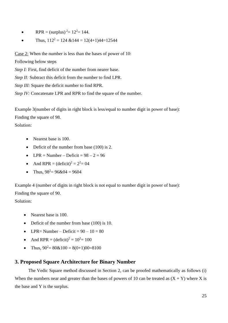
RPR = (surplus) 2= 72= 49.
Thus, 1072 = 114&49 = 11449
Example 2(number of digits in right block is not equal to number digit in power of base):
Finding the Square of 112
Solution:
Nearest base is 100.
Surplus of the number from base (100) is 12.
LPR= number + surplus = 112 + 12 = 124
25
RPR = (surplus) 2= 122= 144.
Thus, 1122 = 124 &144 = 12(4+1)44=12544
Case 2: When the number is less than the bases of power of 10:
Following below steps
Step I: First, find deficit of the number from nearer base.
Step II: Subtract this deficit from the number to find LPR.
Step III: Square the deficit number to find RPR.
Step IV: Concatenate LPR and RPR to find the square of the number.
Example 3(number of digits in right block is less/equal to number digit in power of base):
Finding the square of 98.
Solution:
Nearest base is 100.
Deficit of the number from base (100) is 2.
LPR = Number – Deficit = 98 – 2 = 96
And RPR = (deficit)2 = 22= 04
Thus, 982= 96&04 = 9604
Example 4 (number of digits in right block is not equal to number digit in power of base):
Finding the square of 90.
Solution:
Nearest base is 100.
Deficit of the number from base (100) is 10.
LPR= Number – Deficit = 90 – 10 = 80
And RPR = (deficit)2 = 102= 100
Thus, 902= 80&100 = 8(0+1)00=8100
3. Proposed Square Architecture for Binary Number
The Vedic Square method discussed in Section 2, can be proofed mathematically as follows (i)
When the numbers near and greater than the bases of powers of 10 can be treated as (X + Y) where X is
the base and Y is the surplus.
26
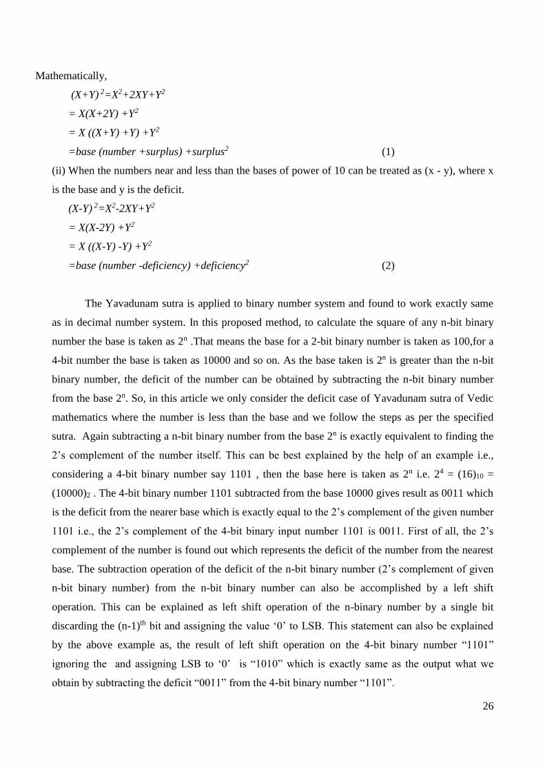
Mathematically,
(X+Y) 2=X2+2XY+Y2
= X(X+2Y) +Y2
= X ((X+Y) +Y) +Y2
=base (number +surplus) +surplus2 (1)
(ii) When the numbers near and less than the bases of power of 10 can be treated as (x - y), where x
is the base and y is the deficit.
(X-Y) 2=X2-2XY+Y2
= X(X-2Y) +Y2
= X ((X-Y) -Y) +Y2
=base (number -deficiency) +deficiency2 (2)
The Yavadunam sutra is applied to binary number system and found to work exactly same
as in decimal number system. In this proposed method, to calculate the square of any n-bit binary
number the base is taken as 2n .That means the base for a 2-bit binary number is taken as 100,for a
4-bit number the base is taken as 10000 and so on. As the base taken is 2n is greater than the n-bit
binary number, the deficit of the number can be obtained by subtracting the n-bit binary number
from the base 2n. So, in this article we only consider the deficit case of Yavadunam sutra of Vedic
mathematics where the number is less than the base and we follow the steps as per the specified
sutra. Again subtracting a n-bit binary number from the base 2n is exactly equivalent to finding the
2’s complement of the number itself. This can be best explained by the help of an example i.e.,
considering a 4-bit binary number say 1101 , then the base here is taken as 2n i.e. 24 = (16)10 =
(10000)2 . The 4-bit binary number 1101 subtracted from the base 10000 gives result as 0011 which
is the deficit from the nearer base which is exactly equal to the 2’s complement of the given number
1101 i.e., the 2’s complement of the 4-bit binary input number 1101 is 0011. First of all, the 2’s
complement of the number is found out which represents the deficit of the number from the nearest
base. The subtraction operation of the deficit of the n-bit binary number (2’s complement of given
n-bit binary number) from the n-bit binary number can also be accomplished by a left shift
operation. This can be explained as left shift operation of the n-binary number by a single bit
discarding the (n-1)th bit and assigning the value ‘0’ to LSB. This statement can also be explained
by the above example as, the result of left shift operation on the 4-bit binary number “1101”
ignoring the and assigning LSB to ‘0’ is “1010” which is exactly same as the output what we
obtain by subtracting the deficit “0011” from the 4-bit binary number “1101”.
27
The result after the shift operation is exactly same as subtracting the deficit from the given input
binary number and this result forms the right part of the result. Then a multiplier is used to obtain
the LPR as multiplication of deficit to itself.
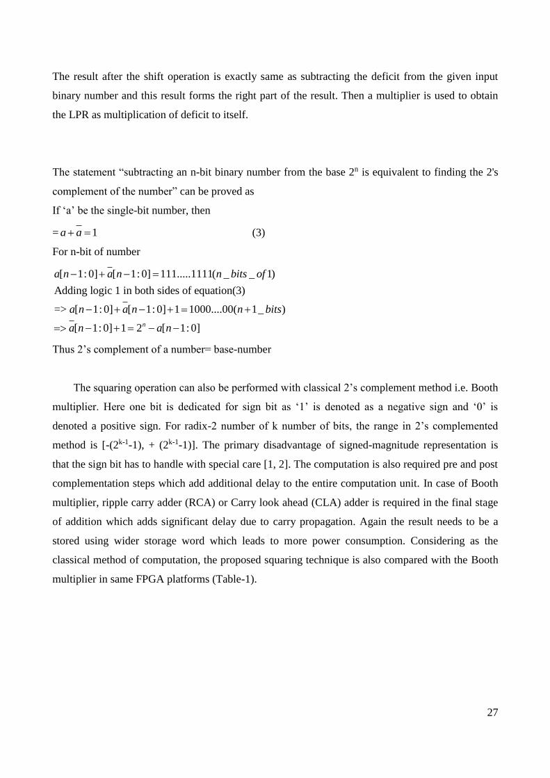
The statement “subtracting an n-bit binary number from the base 2n is equivalent to finding the 2's
complement of the number” can be proved as
If ‘a’ be the single-bit number, then
= 1a a (3)
For n-bit of number
[ 1: 0] [ 1: 0] 111.....1111( _ _ 1)
Adding logic 1 in both sides of equation(3)
=> [ 1: 0] [ 1: 0] 1 1000....00( 1_ )
[ 1: 0] 1 2 [ 1: 0]n
a n a n n bits of
a n a n n bits
a n a n
Thus 2’s complement of a number= base-number
The squaring operation can also be performed with classical 2’s complement method i.e. Booth
multiplier. Here one bit is dedicated for sign bit as ‘1’ is denoted as a negative sign and ‘0’ is
denoted a positive sign. For radix-2 number of k number of bits, the range in 2’s complemented
method is [-(2k-1-1), + (2k-1-1)]. The primary disadvantage of signed-magnitude representation is
that the sign bit has to handle with special care [1, 2]. The computation is also required pre and post
complementation steps which add additional delay to the entire computation unit. In case of Booth
multiplier, ripple carry adder (RCA) or Carry look ahead (CLA) adder is required in the final stage
of addition which adds significant delay due to carry propagation. Again the result needs to be a
stored using wider storage word which leads to more power consumption. Considering as the
classical method of computation, the proposed squaring technique is also compared with the Booth
multiplier in same FPGA platforms (Table-1).
28
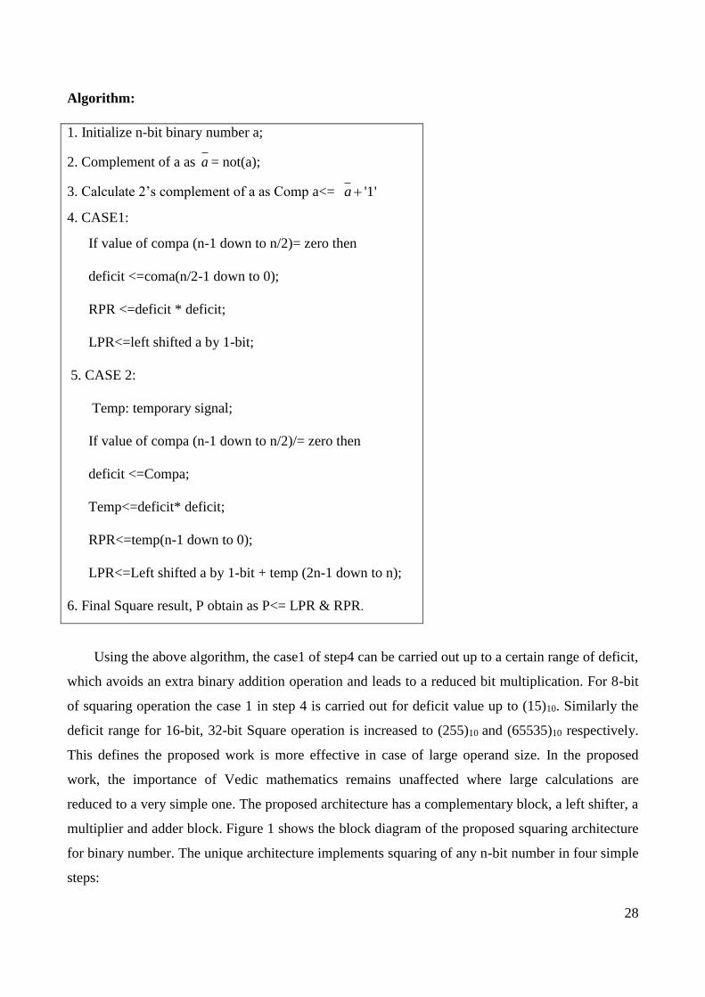
Algorithm:
1. Initialize n-bit binary number a;
2. Complement of a as a = not(a);
3. Calculate 2’s complement of a as Comp a<= '1'a
4. CASE1:
If value of compa (n-1 down to n/2)= zero then
deficit <=coma(n/2-1 down to 0);
RPR <=deficit * deficit;
LPR<=left shifted a by 1-bit;
5. CASE 2:
Temp: temporary signal;
If value of compa (n-1 down to n/2)/= zero then
deficit <=Compa;
Temp<=deficit* deficit;
RPR<=temp(n-1 down to 0);
LPR<=Left shifted a by 1-bit + temp (2n-1 down to n);
6. Final Square result, P obtain as P<= LPR & RPR.
Using the above algorithm, the case1 of step4 can be carried out up to a certain range of deficit,
which avoids an extra binary addition operation and leads to a reduced bit multiplication. For 8-bit
of squaring operation the case 1 in step 4 is carried out for deficit value up to (15)10. Similarly the
deficit range for 16-bit, 32-bit Square operation is increased to (255)10 and (65535)10 respectively.
This defines the proposed work is more effective in case of large operand size. In the proposed
work, the importance of Vedic mathematics remains unaffected where large calculations are
reduced to a very simple one. The proposed architecture has a complementary block, a left shifter, a
multiplier and adder block. Figure 1 shows the block diagram of the proposed squaring architecture
for binary number. The unique architecture implements squaring of any n-bit number in four simple
steps:

29
Step-I:
First of all we find the 2’s complement of the n-bit binary number using complement block which
indicates the deficit of the number from the nearest base.
Step-II:
In the second step, the left shifter block finds left shifted version for any n-bit binary number by a
single bit, whose most significant bit is ignored and the least significant bit is always made zero.
Step-III:
In the third step, we find the Square of the deficit by using multiplier block which multiplies deficit
with the deficit itself which is obtained from Step-I.
Step-IV:
The number of bits after finding the Square of the deficit should be same as that of the given n-bit
input binary number. The low order bits of multiplier represent the right part of the result (RPR). The
higher order bits of multiplier are added to the shifted version of actual number using adder block to
find left part of the result (LPR). Finally, both LPR and RPR parts are concatenated to get the final
result of squaring for any n-bit binary number.
LPR of Result & RPR of Result
Fig.1. Block diagram for the Proposed Squaring Architecture of a binary number
Examples1:
Operand
Left Shift Operation Complement
Adder
Multiplier
30
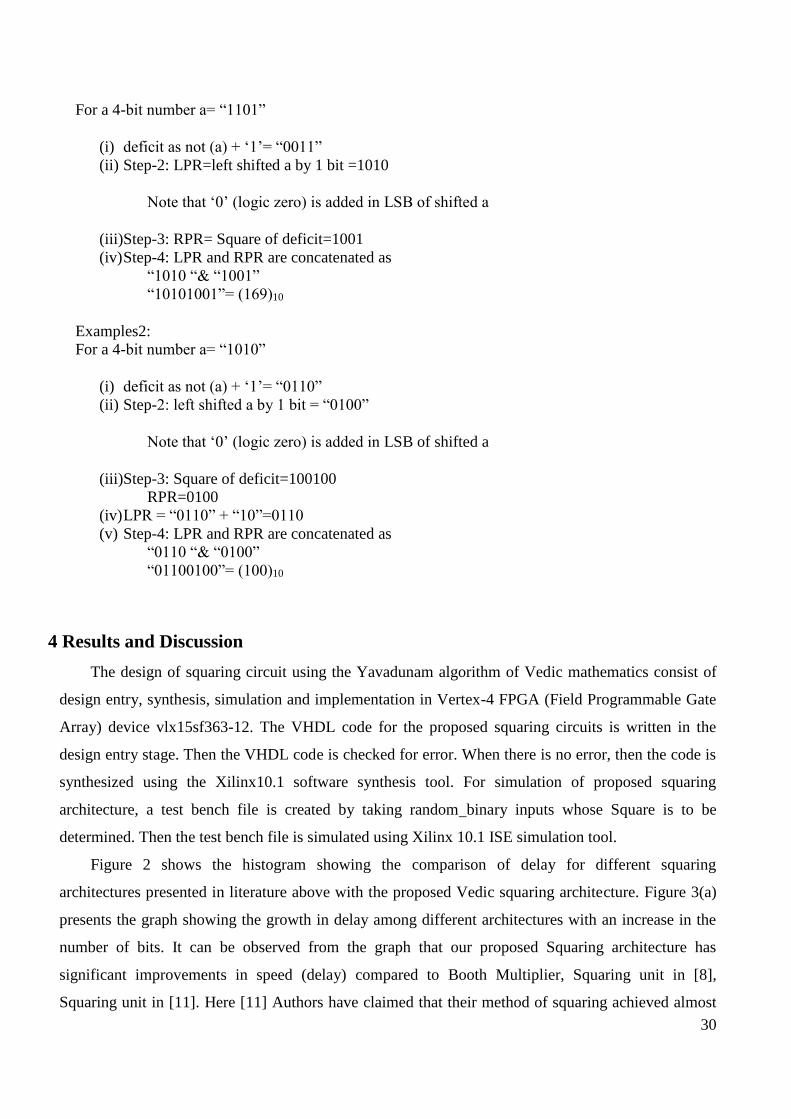
For a 4-bit number a= “1101”
(i) deficit as not (a) + ‘1’= “0011”
(ii) Step-2: LPR=left shifted a by 1 bit =1010
Note that ‘0’ (logic zero) is added in LSB of shifted a
(iii)Step-3: RPR= Square of deficit=1001
(iv) Step-4: LPR and RPR are concatenated as
“1010 “& “1001”
“10101001”= (169)10
Examples2:
For a 4-bit number a= “1010”
(i) deficit as not (a) + ‘1’= “0110”
(ii) Step-2: left shifted a by 1 bit = “0100”
Note that ‘0’ (logic zero) is added in LSB of shifted a
(iii)Step-3: Square of deficit=100100
RPR=0100
(iv) LPR = “0110” + “10”=0110
(v) Step-4: LPR and RPR are concatenated as
“0110 “& “0100”
“01100100”= (100)10
4 Results and Discussion
The design of squaring circuit using the Yavadunam algorithm of Vedic mathematics consist of
design entry, synthesis, simulation and implementation in Vertex-4 FPGA (Field Programmable Gate
Array) device vlx15sf363-12. The VHDL code for the proposed squaring circuits is written in the
design entry stage. Then the VHDL code is checked for error. When there is no error, then the code is
synthesized using the Xilinx10.1 software synthesis tool. For simulation of proposed squaring
architecture, a test bench file is created by taking random binary inputs whose Square is to be
determined. Then the test bench file is simulated using Xilinx 10.1 ISE simulation tool.
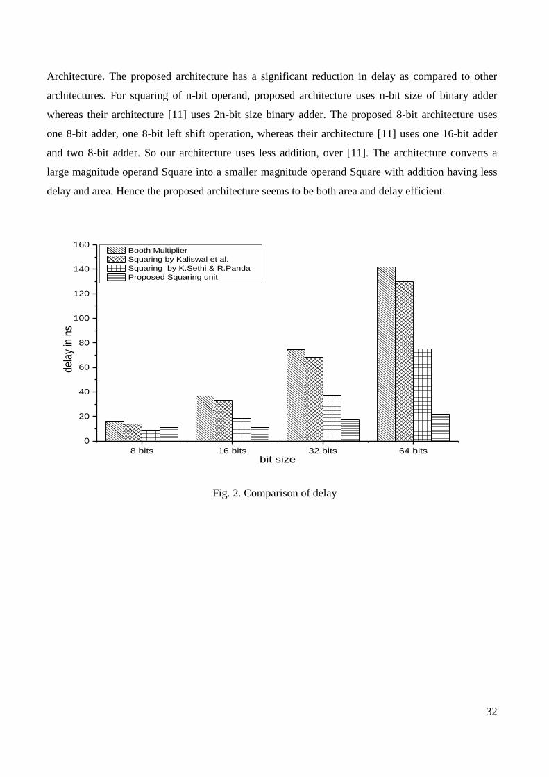
Figure 2 shows the histogram showing the comparison of delay for different squaring
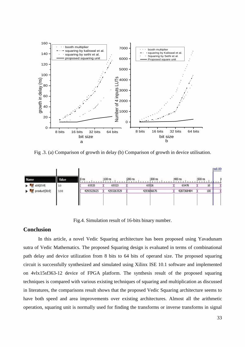
architectures presented in literature above with the proposed Vedic squaring architecture. Figure 3(a)
presents the graph showing the growth in delay among different architectures with an increase in the
number of bits. It can be observed from the graph that our proposed Squaring architecture has
significant improvements in speed (delay) compared to Booth Multiplier, Squaring unit in [8],
Squaring unit in [11]. Here [11] Authors have claimed that their method of squaring achieved almost
31
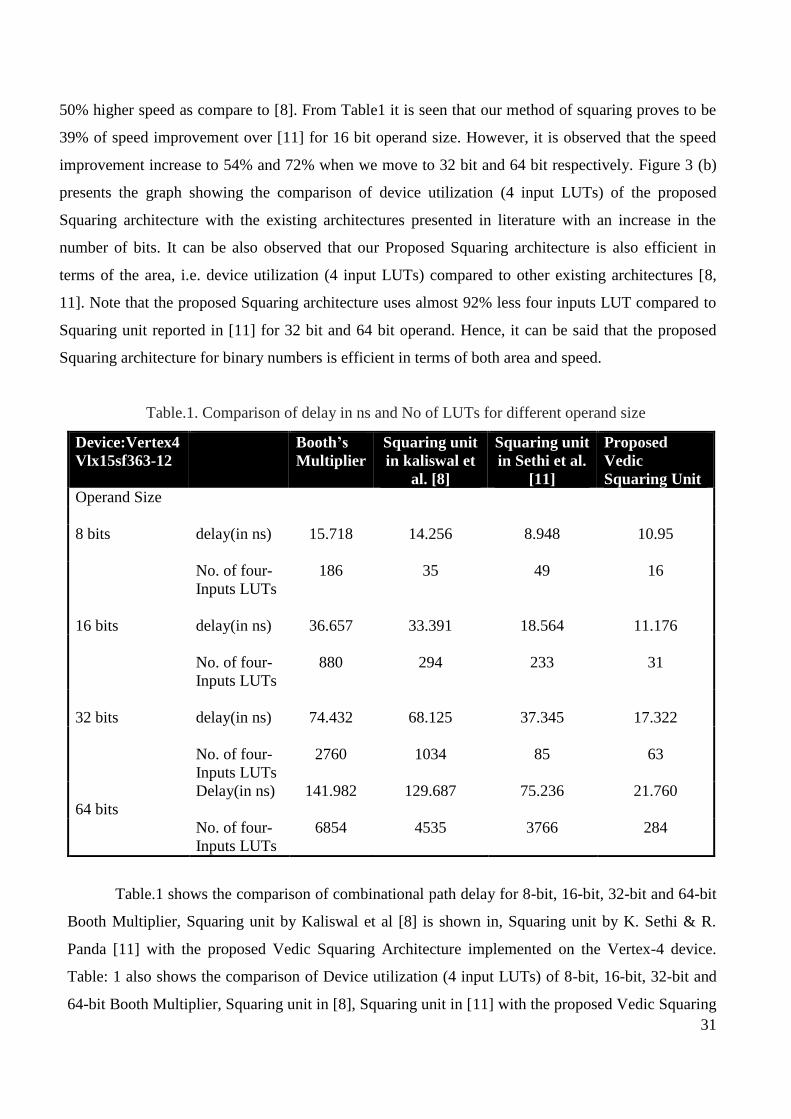
50% higher speed as compare to [8]. From Table1 it is seen that our method of squaring proves to be
39% of speed improvement over [11] for 16 bit operand size. However, it is observed that the speed
improvement increase to 54% and 72% when we move to 32 bit and 64 bit respectively. Figure 3 (b)
presents the graph showing the comparison of device utilization (4 input LUTs) of the proposed
Squaring architecture with the existing architectures presented in literature with an increase in the
number of bits. It can be also observed that our Proposed Squaring architecture is also efficient in
terms of the area, i.e. device utilization (4 input LUTs) compared to other existing architectures [8,
11]. Note that the proposed Squaring architecture uses almost 92% less four inputs LUT compared to
Squaring unit reported in [11] for 32 bit and 64 bit operand. Hence, it can be said that the proposed
Squaring architecture for binary numbers is efficient in terms of both area and speed.
Table.1. Comparison of delay in ns and No of LUTs for different operand size
Device:Vertex4
Vlx15sf363-12
Booth’s
Multiplier
Squaring unit
in kaliswal et
al. [8]
Squaring unit
in Sethi et al.
[11]
Proposed
Vedic
Squaring Unit
Operand Size
8 bits
delay(in ns) 15.718 14.256 8.948 10.95
No. of four-
Inputs LUTs
186 35 49 16
16 bits
delay(in ns)
36.657
33.391
18.564
11.176
No. of four-
Inputs LUTs
880
294
233
31
32 bits
delay(in ns)
74.432
68.125
37.345
17.322
No. of four-
Inputs LUTs
2760
1034
85
63
64 bits
Delay(in ns) 141.982 129.687 75.236 21.760
No. of four-
Inputs LUTs
6854 4535 3766 284
Table.1 shows the comparison of combinational path delay for 8-bit, 16-bit, 32-bit and 64-bit
Booth Multiplier, Squaring unit by Kaliswal et al [8] is shown in, Squaring unit by K. Sethi & R.
Panda [11] with the proposed Vedic Squaring Architecture implemented on the Vertex-4 device.
Table: 1 also shows the comparison of Device utilization (4 input LUTs) of 8-bit, 16-bit, 32-bit and
64-bit Booth Multiplier, Squaring unit in [8], Squaring unit in [11] with the proposed Vedic Squaring
32
Architecture. The proposed architecture has a significant reduction in delay as compared to other
architectures. For squaring of n-bit operand, proposed architecture uses n-bit size of binary adder
whereas their architecture [11] uses 2n-bit size binary adder. The proposed 8-bit architecture uses
one 8-bit adder, one 8-bit left shift operation, whereas their architecture [11] uses one 16-bit adder
and two 8-bit adder. So our architecture uses less addition, over [11]. The architecture converts a
large magnitude operand Square into a smaller magnitude operand Square with addition having less
delay and area. Hence the proposed architecture seems to be both area and delay efficient.
8 bits 16 bits 32 bits 64 bits
0
20
40
60
80
100
120
140
160
de
lay
in n
s
bit size
Booth Multiplier
Squaring by Kaliswal et al.
Squaring by K.Sethi & R.Panda
Proposed Squaring unit
Fig. 2. Comparison of delay
33
8 bits 16 bits 32 bits 64 bits
0
1000
2000
3000
4000
5000
6000
7000
8 bits 16 bits 32 bits 64 bits
0
20
40
60
80
100
120
140
160
Nu
mb
er
of 4
inp
uts
LU
Ts
bit size
booth multiplier
squaring by Kaliswal et al.
Squaring by Sethi et al.
Proposed square unit
b
gro
wth
in d
ela
y (n
s)
bit size
booth multiplier
squaring by kaliswal et al.
squaring by sethi et al.
proposed squaring unit
a
Fig .3. (a) Comparison of growth in delay (b) Comparison of growth in device utilisation.
Fig.4. Simulation result of 16-bits binary number.
Conclusion
In this article, a novel Vedic Squaring architecture has been proposed using Yavadunam
sutra of Vedic Mathematics. The proposed Squaring design is evaluated in terms of combinational
path delay and device utilization from 8 bits to 64 bits of operand size. The proposed squaring
circuit is successfully synthesized and simulated using Xilinx ISE 10.1 software and implemented
on 4vlx15sf363-12 device of FPGA platform. The synthesis result of the proposed squaring
techniques is compared with various existing techniques of squaring and multiplication as discussed
in literatures, the comparisons result shows that the proposed Vedic Squaring architecture seems to
have both speed and area improvements over existing architectures. Almost all the arithmetic
operation, squaring unit is normally used for finding the transforms or inverse transforms in signal
34
processing. More to this the squaring operation is the backbone of the cryptography. So being
efficient in terms of both speed and area the proposed Squaring architecture may be useful for high
performance computer graphics, cryptography, ALU circuits, and many digital image processing
applications.
References
[1] K.Hwang, “Computer arithmetic: principles, architecture and design”. New York, NY: John
Wiley & Sons, 1979.
[2] B. Parhami, "Computer arithmetic algorithms and hardware architectures," Oxford
University Press, New York, vol. 5, 2010.
[3] S. B. K. Tirtha, Vedic mathematics vol. 10: Motilal Banarsidass Publ., India, 1992.
[4] Maharaja, J.S.S.B.K.T. Vedic mathematics, Motilal Banarsidass Publishers Pvt. Ltd, India,
Delhi, 2009.
[5] P. D. Chidgupkar and M. T. Karad, "The implementation of Vedic algorithms in digital
signal processing," Global J. of Engng. Educ, vol. 8, pp. 153-158, 2004.
[6] R. Pushpangadan, V. Sukumaran, R. Innocent, D. Sasikumar, and V. Sundar, "High speed
Vedic multiplier for digital signal processors," IETE Journal of Research, vol. 55, pp. 282-
286, 2009.
[7] M. Pradhan and R. Panda, "Design and implementation of vedic multiplier," AMSE
Journals, Series D, Computer Science and Statistics, vol. 15, pp. 1-19, 2010.
[8] P. S. Kasliwal, B. Patil, and D. Gautam, "Performance evaluation of squaring operation by
Vedic mathematics," IETE journal of Research, vol. 57, pp. 39-41, 2011.
[9] M. Pradhan & R. Panda, “Speed optimization of Vedic multiplier” AMSE journals, Series A
General Mathematics, 49, 21-35, 2012.
[10] M. Pradhan and R. Panda, "High speed multiplier using Nikhilam Sutra algorithm of Vedic
mathematics," International Journal of Electronics, vol. 101, pp. 300-307, 2014.
[11] K. Sethi and R. Panda, "Multiplier less high-speed squaring circuit for binary numbers,"
International Journal of Electronics, vol. 102, pp. 433-443, 2015.
[12] V. A. Pedroni, Digital electronics and design with VHDL: Morgan Kaufmann, 2008.