“Diagnostics of Induction Motor based on Spectral Analysis of...
21
47 AMSE JOURNALS –2014-Series: Advances B; Vol. 57; N° 1; pp 47-67 Submitted Feb. 2013; Revised May 11, 2013; Accepted July 20, 2014 “Diagnostics of Induction Motor based on Spectral Analysis of Stator Current Signal using Fast Fourier Transform and Genetically Tuned Interval type-2 Fuzzy Classifier Methods” 1 Jha Manoj, 2 Kulkarni A.G, 3 Qureshi M.F. 1 Department of Applied Mathematics, Rungta Engineering College, Raipur, India, 492099 ([email protected]) 2 Department of Electronics and Telecommunication, Rungta Engineering College, Raipur, India, 492099 3 Department of Electrical Engg., Govt. Polytechnic Janjgir-Champa, India, 495668 ([email protected]) Abstract A novel diagnostics method of induction motor based on spectral analysis of stator current signal using Fast Fourier Transform (FFT) and genetically tuned interval type-2 fuzzy classifier (GA+IT2FC) is proposed in this paper. New implementation of diagnostics of imminent failure conditions of induction motor was presented. System of current recognition is based on a study of the frequency spectrum of stator using FFT current signal. Interval type-2 Fuzzy classifier was applied. The studies were carried out for four imminent failure conditions of induction motor. The results confirm that the system can be useful for detecting damage and protect the engines. The failure identification techniques applied for condition monitoring of the motor and finally to design an On- line condition monitoring system with interval type-2 fuzzy logic controller is studied. The modeling of three-phase induction motor in three phase reference frame using MATLAB 7 version software and designing an intelligent system for condition monitoring of the induction motor is proposed. Keywords: Genetically tuned interval type-2 fuzzy classifier, Fast Fourier Transform, induction motor, fault diagnosis, condition monitoring. 1. Introduction A three-phase Induction motors may experience several types of fault conditions which include Over load, Ground fault, Line to Line fault, Unbalanced supply voltage, Over voltage, Under voltage, Single phasing, Turn to Turn fault. When one of the three-phases to the motor is open, single
Transcript of “Diagnostics of Induction Motor based on Spectral Analysis of...

47
AMSE JOURNALS –2014-Series: Advances B; Vol. 57; N° 1; pp 47-67 Submitted Feb. 2013; Revised May 11, 2013; Accepted July 20, 2014
“Diagnostics of Induction Motor based on Spectral Analysis of Stator Current Signal using Fast Fourier Transform and Genetically Tuned
Interval type-2 Fuzzy Classifier Methods”
1Jha Manoj, 2Kulkarni A.G, 3Qureshi M.F.
1Department of Applied Mathematics, Rungta Engineering College, Raipur, India, 492099 ([email protected])
2Department of Electronics and Telecommunication, Rungta Engineering College,
Raipur, India, 492099 3Department of Electrical Engg., Govt. Polytechnic Janjgir-Champa, India, 495668
Abstract A novel diagnostics method of induction motor based on spectral analysis of stator current
signal using Fast Fourier Transform (FFT) and genetically tuned interval type-2 fuzzy classifier
(GA+IT2FC) is proposed in this paper. New implementation of diagnostics of imminent failure
conditions of induction motor was presented. System of current recognition is based on a study of the
frequency spectrum of stator using FFT current signal. Interval type-2 Fuzzy classifier was applied.
The studies were carried out for four imminent failure conditions of induction motor. The results
confirm that the system can be useful for detecting damage and protect the engines. The failure
identification techniques applied for condition monitoring of the motor and finally to design an On-
line condition monitoring system with interval type-2 fuzzy logic controller is studied. The modeling
of three-phase induction motor in three phase reference frame using MATLAB 7 version software and
designing an intelligent system for condition monitoring of the induction motor is proposed.
Keywords:
Genetically tuned interval type-2 fuzzy classifier, Fast Fourier Transform, induction motor,
fault diagnosis, condition monitoring.
1. Introduction
A three-phase Induction motors may experience several types of fault conditions which
include Over load, Ground fault, Line to Line fault, Unbalanced supply voltage, Over voltage, Under
voltage, Single phasing, Turn to Turn fault. When one of the three-phases to the motor is open, single
48
phasing situation occurs. This result increased positive and negative sequence currents and hence
excessive heating. Unbalance supply voltage results in negative sequence voltage. It leads to increase
in positive and negative sequence current components. Ground and line faults are prevalent in motors
than other power system devices. These faults are detected by observing the zero sequence current.
Similarly Turn to Turn short and coil open faults can cause current unbalance. The focus has been on
the use of On-line condition monitoring to detect degradation processes and failure mechanisms. It is
necessary to treat each induction motor drive as a unique entity and the potential failure modes
fundamental causes, mechanical load characteristics, and operation conditions have all to be taken into
consideration when a condition monitoring system is being selected. Failure of insulation between
winding and ground can cause large ground current, which would result in irreversible damage to the
core of the machine. If the fault is detected at an early stage, the machine can be put back into service
by just rewinding the stator on the other hand, replacing the motor means increased downtime. Typical
protection for stator insulation failure in an industrial environment includes the use of ground fault
relays and negative sequence or phase current balance relays would cause nonsense trips with
unbalanced line voltages. Ground fault relays would not be effective for early fault detection. Sensor
less methods for detection of turn-faults are based on monitoring the line currents and voltages for an
electrical asymmetry caused by turn-turn short circuits in the winding. For line connected machines,
the negative sequence current is the fundamental fault signature for a winding fault. Turn fault
detection based on the axial leakage component flux and electrically excited vibrations have also been
existing, however, the sequence components approach provides a better signal to noise ratio, is easier
to measure and does not require any special instrumentation besides current sensors. The sensitivity of
sequence components based turn-fault detection schemes depends on the extent to which the effects of
non-idealities are compensated. The negative sequence current is affected by unbalance in power
supply and inherent asymmetries in the machine and in instrumentation. Motor Current Signature
Analysis can detect the fault before a phase-phase or phase-earth failure. It is therefore possible with a
low voltage stator winding to have some lead time between shorted turns developing and actual
failure. The good condition of electrical machines can be obtained by using diagnostics. There are lots
of methods that can be used for diagnostics of electrical machines. In the literature, popular methods
are based on a study of electrical signals. The paper presents new implementation of diagnostics of
imminent failure conditions of induction motor. Study of information contained in signal of stator
current is one of the tasks that must be done to properly build workstation of current recognition of
induction motor. Information contained in the stator current signal should contain indications of failure
of electrical machine. Devices for recording signals of the stator current at frequencies from 1 Hz to
409 Hz have low price and are available. Therefore we will conduct research in the frequency range
from 1 Hz to 409 Hz. The greatest difficulties arise when the engineer must choose the method of

49
signal processing and analysis of current. However, the differences in signal cause that the methods
used are not always effective to recognize. It should be noted that some of the harmonic frequencies of
the signal of current of the damaged and undamaged motor are different. Solving this problem is to
find the appropriate choice of signal processing algorithms in order to detect small differences in the
current of induction motor.
2. Stator Current Recognition Process of Induction Motor The process of current recognition of induction motor contains pattern creation process and
identification process. At the beginning of pattern creation process current signals are recorded. After
that system divides data. Next signals are sampled, normalized and filtrated. Afterwards data are
converted through the Hamming window (window size 512). Next data are converted through the FFT
algorithm. FFT algorithm creates feature vectors (256 features). After that patterns of interval type-2
fuzzy sets (IT2FS) are created. Steps of identification process are the same as for pattern creation
process (Fig.1). Significant change occurs in the classification. In this step, interval type-2 fuzzy sets
are compared with each other (patterns of interval type-2 fuzzy sets and new interval type-2 fuzzy
sets).
Result
Fig.1 Pattern creation process and identification process with
application of FFT and GA tuned interval type-2 fuzzy classifier(IT2FC)
Current Signal Recording Device
Signal Processing System (SPS)
Data Containing Current
Data Division
Data Renaming
Divided Data
Current Recognition
System (CRS)
AFS Preprocessing
Hamming Window Scheme of Feature Identification Process
Extraction
Sampling
Amplitude Normalization
Filtration (4 Hz-409 Hz)
Windowing FFT
Patterns of Interval Type-2 Fuzzy Sets(IT2FSs)
Interval Type-2 Fuzzy Classifier (IT2FC)
GA Tuning
50
This paper presents a signal processing method is called amplitude recovery method that can
be used as the signal pre-processing for fast Fourier transform (FFT) in order to analyze the
spectrum of the other-order harmonics rather than the fundamental frequency in stator currents and
diagnose subtle faults in induction motors. In this situation, the amplitude recovery system
functions as a filter that can filter out the component of the fundamental frequency from three
phases of stator currents of the induction motor. As it works as a filter hence called Amplitude
Filtering System (AFS). The filtering result of the AFS can be provided to FFT to do further
spectrum analysis. In this way, the amplitudes of other-order frequencies can be extracted and
analyzed independently. If the FFT is used without the AFS pre-processing and the components of
other-order frequencies, compared to the fundamental frequency, are fainter, the amplitudes of
other- order frequencies are not able easily to extract out from stator currents. The reason is when
the FFT is used direct to analyze the original signal; all the frequencies in the spectrum analysis of
original stator current signal have the same weight. The ARM is capable of separating the other-
order part in stator currents from the fundamental-order part. The diagnosis application of AFS
combined with FFT is also displayed in this paper with the experimented induction motor.
3. Spectrum analysis on stator currents of induction motors
Indicated in many studie, the faults of induction motors can be localized on the stator
windings, bearings, rotors or shafts. They, furthermore, can be divided into two groups: one is
called E-problems and related to electrical parts (such as stator windings or rotor circuits); the other
is called M-problems and referred to mechanical parts (such as bearings or shafts). Stator currents
can provide very rich information on broken bars or rings, misalignment and eccentricities. The
amplitude of some rotor faults allows dimensioning the failure’s degree. Therefore, the stator
current spectrum of induction motors can reflect the faults. According to the analyses in, most of the
faults in induction motors, except the stator winding problems are subtle and sensitive to some
specific groups of harmonic frequencies in stator currents The frequency of current flowing in the
unbalanced rotor is sfs, where fs is the frequency of the supply phase current and s is the slip. With
the effect of the rotor speed fluctuation, the emf induces two additional currents of the (1-2s) fs and
(1+2s)fs frequency. The stator current at frequency (1-2s) fs is the sum of the two components at
frequency (1-2s)fs: one is the initial component induced by the rotor asymmetry; the other is a
reaction of the initial component. The stator current at frequency (1+2s) fs also consists of two
similar components as the stator current at frequency (1-2s) fs does. The rotating magnetic field
continue store produce the stator current components. Therefore, the harmonics in the stator current
related to the rotor circuit problems can be with the frequencies that are proportional to the
frequency of the supply phase current and influenced by the slip as the following:

51
(1)
Where fs is the frequency of the supply phase current, k=1,2, y, and s the slip.
Bearing problems in M-problems can be the periodic impulses in the vibration signal, and
caused by the local defects or wear defects. According to the different fault locations, the
frequencies can be divided into four types. The first one is the fundamental cage frequency:
(2)
Where fr is the shaft rotation frequency, d the roller diameter, D the pitch diameter of the
bearing, and θ the contact angle between the rollers and the ball bearing rings. These condone is the
ball defect frequency:
(3)
The third one is the inner race defect frequency
(4)
And the final one is the outer race defect frequency
(5)
Where nb is the number of rollers. The frequencies of these impulses are determined by the
shaft rotational speed, fault location, and bearing dimensions. These mechanical vibrations cause
the variant of the flux density in the air gap and result in the modulation of stator currents.
Therefore, the frequencies of the harmonics related to bearing problems in stator currents can be
calculated by
(6)
Where m = 1,2,3, y and fv is one of the frequencies that are calculated. There are two types
of eccentricity, the static eccentricity and dynamic eccentricity. In the former, the position of
minimum air gap is fixed in the space, which can be caused by the ovality of the stator or the
incorrect placement of the rotor or stator during the assembly. In the latter, the position of minimum
air gap changes in time and space, which can be resulted from the deformation of the rotor axis,
bearing wear or misalignment, or the mechanical resonance at the critical speed. If the slot

52
frequency is set to the supply frequency, the sideband components around the slot frequency can be
given by
(7)
Where k=1,2,3 ….y, R is the number of rotor bars, p the number of pole pairs, nds=1 for the
dynamic eccentricity and 0 for the static eccentricity, and nad the order of magneto motive force
(mmf) of the stator slot harmonic. Therefore, it can be summarized that most of the faults in the
induction motors, except the stator winding problems, are subtle and sensitive to some harmonics in
the stator currents. It is possible and necessary to diagnose these subtle faults to protect the motors
from serious latent damages .As these subtle faults are related to the frequencies different from the
supply frequency that is the fundamental frequency in three phases of the stator currents of the
induction motor, the components of other order frequencies need to be separated from the one of the
fundamental frequency. This is the purpose of the AFS.
Signal Processing
The signals to be analyzed are acquired through signal conditioning circuits and DAQ card.
This is shown in Fig.2. After acquisition the signal is brought to the actual magnitude by suitable
multiplication factor.
Fig.2 Schematic diagram of the actual setup
The signal processing has been convergent into Spectrum analysis as detailed below:
Spectrum analysis using FFT
The samples of the signal obtained from the DAQ card constitute the time domain
representation of the signal. This representation gives the amplitudes of the signal at the instants of
time during which it had been sampled. However, in the fault diagnosis of induction motor, it is
required to know the frequency content of the current signal rather than the amplitudes of the
individual samples. The representation of the signal in terms of its individual frequency components
is known as the frequency domain representation of the signal. The frequency domain

53
representation could give more insight about the signal and the system. The algorithm used to
transform samples of the data from the time domain into the frequency domain is known as the Fast
Fourier Transform (FFT). The FFT establishes the relationship between the samples of a signal in
the time domain and their representation in the frequency domain. The FFT is widely used in the
fields of spectral analysis. If the signal is sampled at a sampling rate of fs Hz, then the time interval
between the samples is Δt, where
(8)
The Fast Fourier Transform is given by
for k=0,1,2,…N-1 (9)
Where X(t) is the frequency domain representation.
(10)
The time domain 'x' and the frequency domain 'X' have a total of N samples. If the FFT is
complex, it contains two pieces of information-the amplitude and phase.
(11)
The objective of performing FFT analysis on the current signal is to identify current
components in the stator winding that are function of shorted turns. The following equation gives
the components in the air gap flux waveform that are a function of shorted turns. The components
are clearly a function of motor design, in a four pole, three phase, squirrel cage induction motor,
from equation (11) there will be a whole series of components,
And so on with combinations of k and n values.
4. Genetically Tuned Interval Type-2 Fuzzy Classifier Design
54
Interval Type-2 Fuzzy classifier with Gaussian membership function
If for a type-1 membership function, we blur it to the left and to the right, then a type-2
membership function is obtained. A type-2 fuzzy set à is characterized by the membership
function:
(12)
In which another expression for à is
(13)
Where ∫∫ denotes the union over all admissible input variables x and u. For discrete universes
of discourse ∫ is replaced by Σ (Mendel and John, 2002). In fact Jx ⊆ [0,1] represents the primary
membership of x, and (x,u) is a type-1 fuzzy set known as the secondary set. Hence, a type-2
membership grade can be any subset in [0,1], the primary membership, and corresponding to each
primary membership, there is a secondary membership (which can also be in [0,1]) that defines the
possibilities for the primary membership (Liang and Mendel, 2000). Uncertainty is represented by a
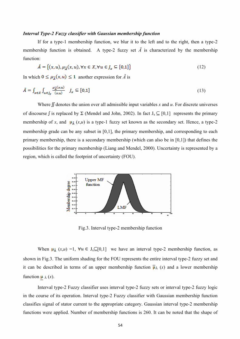
region, which is called the footprint of uncertainty (FOU).
Fig.3. Interval type-2 membership function
When (x,u) =1, Jx⊆[0,1] we have an interval type-2 membership function, as
shown in Fig.3. The uniform shading for the FOU represents the entire interval type-2 fuzzy set and
it can be described in terms of an upper membership function à (x) and a lower membership
function à (x).
Interval type-2 Fuzzy classifier uses interval type-2 fuzzy sets or interval type-2 fuzzy logic
in the course of its operation. Interval type-2 Fuzzy classifier with Gaussian membership function
classifies signal of stator current to the appropriate category. Gaussian interval type-2 membership
functions were applied. Number of membership functions is 260. It can be noted that the shape of

55
membership functions will have not a major impact on the recognition of current (Fig.3). Basis of
the Gaussian shape is a parameter that has to be chosen depending on the data obtained as a result
of the FFT algorithm (feature vector). Data collection and parameter of Gaussian interval type-2
membership functions have significant impact on the recognition of the current. Research will be
carried out with different parameter of Gaussian membership functions.
Rules
The structure of rules in a type-1 FLS and a type-2 FLS is the same, but in the latter the
antecedents and the consequents will be represented by type-2 fuzzy sets. So for a type-2 FLS with
p inputs x1 X1,…,xp Xp and one output y Y, Multiple Input Single Output (MISO), if we assume
there are M rules, the lth rule in the type-2 FLS can be written as follows:
(14)
As GA’s deal with coded parameters, all parameters that need to be tuned must be encoded
into a finite length of string or gene. The encoded genes are concatenated to form a complete
chromosome. For the tuning of membership function the following equations were defined:
(15)
Where ki, ji are adjustment coefficient, Cx, and Wx are set of centre and width of each fuzzy
membership function. It means ki makes each center of membership function move to the right or
left and ji makes them wider or sharper, as shown in Fig.4. After that, the adjustment coefficients
are encoded to form the population:
Gene |1|,…,|6|,|7|,|8|,..|12|,|13|,|14|,…,|18|,|19|
Chromosome |subchrom1|,|subchrom2,|,| sumchrom3 |
Chromosome |....k1ij1i…..|,|....k2ij2i..…..|,|…..k3ij3i…...| (16)
Parameter | ....(MF1)...|,|...(MF2)|…|,|...(MF3)……|
Fig. 4 Principle in tuning of membership function
In another side, for rule base searching, each of the parameter is encoded into integer codes
that are based on number of output membership function. It means there are ‘1’, ‘2’, and ‘3’ for

56
LOW, MEDIUM, and HIGH for speed output. The coded parameters are arranged as shown in the
following equation to form chromosome of the population.
Gene |1|, |2|, … , |26|,|27|, |28|,|29|, …, |53|, |54|
Chromosome |sub-chromosome1|, | sub-chromosome2 |
Parameter | ……..(RB1)….....|, | ……..(RB2)|…… .| (17)
GA’s process starts with randomly generated initial populations. Then, all chromosomes are
evaluated and associated base on fitness function with linear ranking method to determine the
members of the new generation population. Let (p1…..pN) be a family of representative input values
for which the desired output fuzzy sets (O1….ON) are known and let O(v,p) be the output fuzzy set
which is obtained when the output of the fuzzy system is evaluated for input p with respect to the
configuration v. In the case that the output variable has a finite universe of discourse (x0….. xn-1).
The fitness functions for obstacle avoiding as:
(18)
For each class represented within a hyper-region, specificity and a selectivity of that region
for that class can be assigned. Specificity of a situation S in region R and having class C is the
probability of S being of class C given having non-zero membership of the region R. Selectivity of
a situation S in region R and having class C is the probability of S having non-zero membership of
region R given class C. S may have a non-zero degree of membership within more than one region,
so to compute fitness we first compute the specificity of S multiplied by log of selectivity of S
within each of the regions for which it has a degree of membership, take the maximum of absolute
value of all these as the contribution of the situation to the fitness function and sum over all
situations.
(19)
(20)
(21)
GAs is optimization stochastic technique mimicking the natural selection, which consists of
three operations, namely, reproduction, crossover, and mutation. In practice, training data can be
obtained by experimentation or by the establishment of an ideal model. Fig.5 shows the training
process for each fuzzy module involved in the self-tuning system.
57
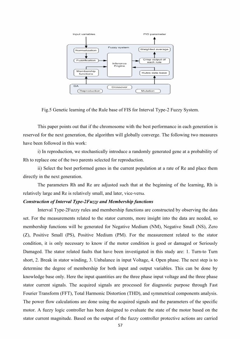
Fig.5 Genetic learning of the Rule base of FIS for Interval Type-2 Fuzzy System.
This paper points out that if the chromosome with the best performance in each generation is
reserved for the next generation, the algorithm will globally converge. The following two measures
have been followed in this work:
i) In reproduction, we stochastically introduce a randomly generated gene at a probability of
Rh to replace one of the two parents selected for reproduction.
ii) Select the best performed genes in the current population at a rate of Re and place them
directly in the next generation.
The parameters Rh and Re are adjusted such that at the beginning of the learning, Rh is
relatively large and Re is relatively small, and later, vice-versa.
Construction of Interval Type-2Fuzzy and Membership functions
Interval Type-2Fuzzy rules and membership functions are constructed by observing the data
set. For the measurements related to the stator currents, more insight into the data are needed, so
membership functions will be generated for Negative Medium (NM), Negative Small (NS), Zero
(Z), Positive Small (PS), Positive Medium (PM). For the measurement related to the stator
condition, it is only necessary to know if the motor condition is good or damaged or Seriously
Damaged. The stator related faults that have been investigated in this study are: 1. Turn-to Turn
short, 2. Break in stator winding, 3. Unbalance in input Voltage, 4. Open phase. The next step is to
determine the degree of membership for both input and output variables. This can be done by
knowledge base only. Here the input quantities are the three phase input voltage and the three phase
stator current signals. The acquired signals are processed for diagnostic purpose through Fast
Fourier Transform (FFT), Total Harmonic Distortion (THD), and symmetrical components analysis.
The power flow calculations are done using the acquired signals and the parameters of the specific
motor. A fuzzy logic controller has been designed to evaluate the state of the motor based on the
stator current magnitude. Based on the output of the fuzzy controller protective actions are carried
58
out. The total Instrumentation system incorporates: 1. Data Acquisition., 2. Signal Processing, 3.
Fuzzy Control
Interval Type-2Fuzzy Control
In the motor fault diagnosis process, time domain current signals are captured from sensors.
The diagnostic expert then uses both time domain and frequency domain signals to study the motor
condition and determines what faults are present. However, experienced engineers are often
required to interpret measurement data that are frequently inconclusive. A Interval Type-2Fuzzy
logic approach may help to diagnose induction motor faults. While conducting fault diagnosis, there
are several situations in which an object is not obviously "Good" or "Damaged", but may fall into
some interior range. Here the motor condition is described using linguistic variables (like an
electrical machine referred as "somewhat secure", "little overloaded"). Interval Type-2 Fuzzy
subsets and the corresponding membership functions describe stator current amplitudes. This
linguistic input can be expressed directly by a interval type-2 fuzzy system. The stator current signal
contains potential fault information. Interval Type-2 Fuzzy systems rely on a set of rules. These
rules, allow the input to be fuzzy, i.e. like the natural way that
Ia = { µia (Iaj) Σ Ia },Ib = { µib (Ibj) Σ Ib },Ic = { µic (Icj) Σ Ic } and CM = { µcm (cmj) Σ CM }
Where Iaj , Ibj , Icj and cmj are elements of the discrete universe of discourse Ia, Ib, Ic and
Condition Monitoring(CM). the optimized rule base has been developed so as to cover all the
healthy and the faulty conditions of the motor. In this case the stator current Ia, Ib, and Ic are
considered input variables to the interval type-2 fuzzy system. The stator condition, CM is chosen
as output variable. All the system inputs and outputs are defined using interval type-2 fuzzy sets.
The input variables are interpreted as linguistic variables, with Negative Medium (NM), Negative
Small (NS), Zero (Z), Positive Small (PS) and Positive Medium (PM). Similarly the output variable
stator condition (CM) is interpreted as linguistic variables, with Good, Damaged, and Seriously
Damaged.
Rule Base
1. If Ia is NM and Ib is NM and Ic is NM then CM is Good
2. If Ia is NM and Ib is Zero and Ic is Zero then CM is Damaged
3. If Ia is NM and Ib is Zero and Ic is PS then CM is Seriously Damaged
4. If Ia is Zero and Ib is NM and Ic is Zero then CM is Damaged
5. If Ia is Zero and Ib is NM and Ic is PS then CM is Seriously Damaged
6. If Ia is PS and Ib is NM and Ic is PS then CM is Damaged
7. If Ia is PS and Ib is Zero and Ic is NM then CM is Seriously Damaged
8. If Ia is Zero and Ib is PS and Ic is Zero then CM is Damaged
9. If Ia is Zero and Ib is Zero and Ic is Zero then CM is Good
59
10. If Ia is PS and Ib is PS and Ic is Zero then CM is Good
Defuzzification is defined as the conversion of interval type-2 fuzzy output to crisp output.
Here we used Center of Area (COA) method for defuzzification. Output (CM) of Interval Type-2
Fuzzy Logic Controller: 1. Good ----- 70 TO 100, 2. Damaged ----- 30 To 70, 3. Seriously Damaged
----- 0 To 30 If any incipient faults are slight voltage unbalance occurs, then the output of the
interval type-2 fuzzy controller will go Damaged. Immediately the fault data and the current
spectrum are stored in a file for analysis purpose with time as long as fault persists. At the same
time a warning indication will be given to the operator, and a beep sound will be generated at the
central processing unit of the computer to alert the operator at the shop as well as the control room
engineer. Whenever the interval type-2 fuzzy controller output goes seriously damaged, the
machine will be isolated from the supply and the instantaneous fault data are stored, also the front
panel of the monitoring system will display the possible cause seriously damaged state of the motor.
After performing the above said operations the program will be stopped.
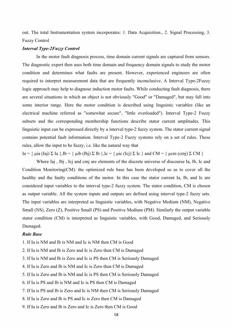
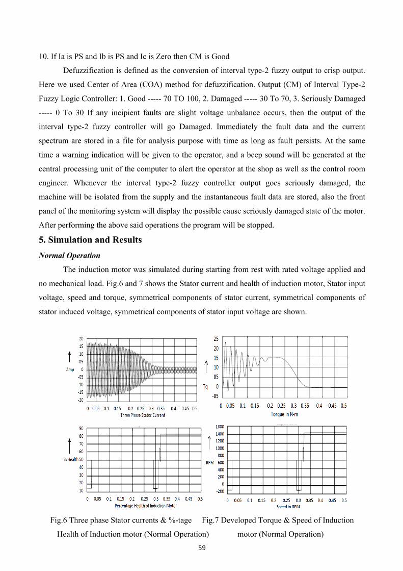
5. Simulation and Results Normal Operation
The induction motor was simulated during starting from rest with rated voltage applied and
no mechanical load. Fig.6 and 7 shows the Stator current and health of induction motor, Stator input
voltage, speed and torque, symmetrical components of stator current, symmetrical components of
stator induced voltage, symmetrical components of stator input voltage are shown.
Fig.6 Three phase Stator currents & %-tage Fig.7 Developed Torque & Speed of Induction
Health of Induction motor (Normal Operation) motor (Normal Operation)
60
From these results it can be concluded that after the transient period is over, the health of the motor
is good, and there is no negative sequence component in both stator induced voltage and stator
current.
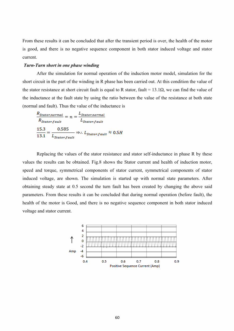
Turn-Turn short in one phase winding
After the simulation for normal operation of the induction motor model, simulation for the
short circuit in the part of the winding in R phase has been carried out. At this condition the value of
the stator resistance at short circuit fault is equal to R stator, fault = 13.1Ω, we can find the value of
the inductance at the fault state by using the ratio between the value of the resistance at both state
(normal and fault). Thus the value of the inductance is
Replacing the values of the stator resistance and stator self-inductance in phase R by these
values the results can be obtained. Fig.8 shows the Stator current and health of induction motor,
speed and torque, symmetrical components of stator current, symmetrical components of stator
induced voltage, are shown. The simulation is started up with normal state parameters. After
obtaining steady state at 0.5 second the turn fault has been created by changing the above said
parameters. From these results it can be concluded that during normal operation (before fault), the
health of the motor is Good, and there is no negative sequence component in both stator induced
voltage and stator current.

61
Fig.8 Symmetrical component waveforms of stator current (Turn-Turn short)
As soon as the fault is created the stator current becomes unbalanced, and the health of the
induction motor goes seriously damaged and finally settles to Damaged state, and we can notice that
there is presence of negative sequence component in both stator induced voltage and stator current
waveforms during fault conditions.
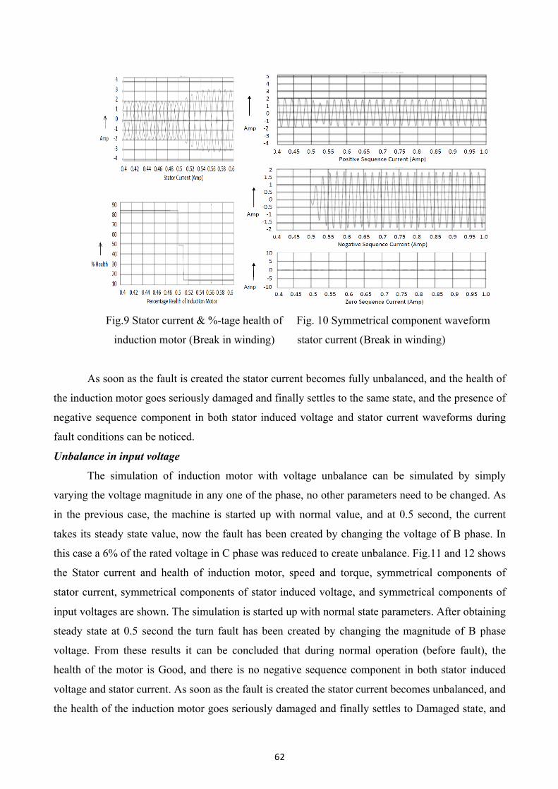
Break in stator winding
For simulation of the break fault in the stator winding at R phase, it is not possible to apply a
break in the phase by putting the value of the stator resistance and the stator inductance to infinity.
It is assumed that the value of the stator resistance is very large and corresponding to this value we
can calculate the value of the inductance by this equation:
Replacing the values of the stator resistance and stator self-inductance in phase R by these
values, the fault state results can be obtained. Fig.9 and 10, shows the Stator current and health of
induction motor, speed and torque, symmetrical components of stator current, symmetrical
components of stator induced voltage, are shown. The simulation is started up with normal state
parameters. After obtaining steady state at 0.5 second the break in winding fault has been created by
changing the above said parameters. From these results it can be concluded that during normal
operation (before fault), the health of the motor is Good, and there is no negative sequence
component in both stator induced voltage and stator current.
62
Fig.9 Stator current & %-tage health of Fig. 10 Symmetrical component waveform
induction motor (Break in winding) stator current (Break in winding)
As soon as the fault is created the stator current becomes fully unbalanced, and the health of
the induction motor goes seriously damaged and finally settles to the same state, and the presence of
negative sequence component in both stator induced voltage and stator current waveforms during
fault conditions can be noticed.
Unbalance in input voltage
The simulation of induction motor with voltage unbalance can be simulated by simply
varying the voltage magnitude in any one of the phase, no other parameters need to be changed. As
in the previous case, the machine is started up with normal value, and at 0.5 second, the current
takes its steady state value, now the fault has been created by changing the voltage of B phase. In
this case a 6% of the rated voltage in C phase was reduced to create unbalance. Fig.11 and 12 shows
the Stator current and health of induction motor, speed and torque, symmetrical components of
stator current, symmetrical components of stator induced voltage, and symmetrical components of
input voltages are shown. The simulation is started up with normal state parameters. After obtaining
steady state at 0.5 second the turn fault has been created by changing the magnitude of B phase
voltage. From these results it can be concluded that during normal operation (before fault), the
health of the motor is Good, and there is no negative sequence component in both stator induced
voltage and stator current. As soon as the fault is created the stator current becomes unbalanced, and
the health of the induction motor goes seriously damaged and finally settles to Damaged state, and
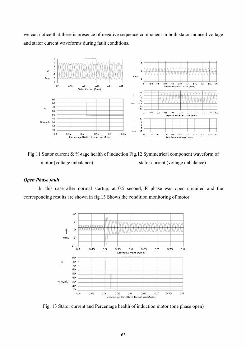
63
we can notice that there is presence of negative sequence component in both stator induced voltage
and stator current waveforms during fault conditions.
Fig.11 Stator current & %-tage health of induction Fig.12 Symmetrical component waveform of
motor (voltage unbalance) stator current (voltage unbalance)
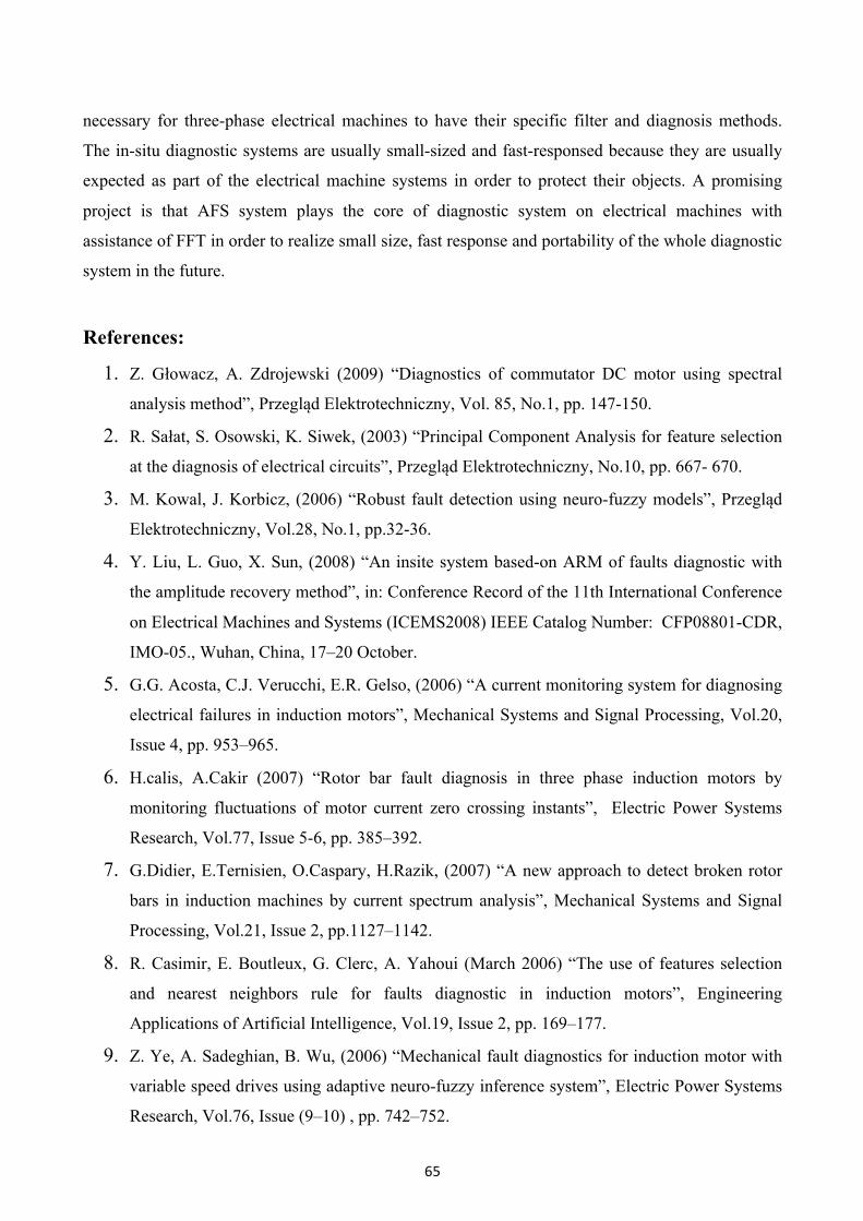
Open Phase fault
In this case after normal startup, at 0.5 second, R phase was open circuited and the
corresponding results are shown in fig.13 Shows the condition monitoring of motor.
Fig. 13 Stator current and Percentage health of induction motor (one phase open)

64
6. Discussion Moreover, the number of channels was 1, the number of samples was 16384, the period of
sampling was 1221µs, power supply was 220V, nN = 1400 rpm. Pattern creation process was
carried out for eight one-second samples. New samples were used in the identification process.
Twelve one-second samples were used for each category. The system should determine the state of
induction motor correctly.
Efficiency of current recognition is defined as:
Where: S is efficiency of current recognition, N1 is number of correctly identified samples
and N is number of all samples. The best recognition results were obtained using the normalization
of the amplitude and the filter that passed frequencies from 4 Hz to 409 Hz. Parameter of triangular
membership function was 0.00002. Efficiency of current recognition of faultless induction motor
was 100%. Efficiency of current recognition of induction motor with faulty ring of squirrel cage
was 100%. Efficiency of current recognition of induction motor with one faulty bar was 66.66%.
Efficiency of current recognition of induction motor with two faulty bars was 83.33%. Current
recognition system was designed and implemented for induction motor. Results of current
recognition were good for FFT and genetically tuned interval type-2 fuzzy classifier with Gaussian
membership function. Filter that passed frequencies from 4 Hz to 409 Hz was applied. Efficiency of
current recognition of induction motor was 66.66 - 100%. Time of performance of identification
process of one-second sample was 1.075 s for Intel Pentium M 730 processor (normalization,
filtration: 4 - 409 Hz, FFT, fuzzy classifier). Current recognition system can be useful for detecting
damage and protect the engines. In the future, the current recognition system of induction motor can
be applied with other effective data processing algorithms and soft computing methods.
7. Conclusions A FFT and Genetically tuned interval type-2 fuzzy classifier based measurement and health
evaluation system has been developed and implemented. This application allows fast failure state
estimation. The more detailed investigation to point out the difficult conditions of the machine
under different stator fault conditions of induction motor can be performed. This is a highly
versatile technology for condition monitoring and fault analysis of motors. It solves the shutdown
Problems and ensures safe working environment in continuous process industry. The AFS
algorithm can filter out the fundamental component in stator current sophisticated induction motor
and have the other-order harmonics left, which can help detect and diagnose the subtle faults in the
tested induction motor. AFS must be applied in three phases of currents in electrical machine. It is
65
necessary for three-phase electrical machines to have their specific filter and diagnosis methods.
The in-situ diagnostic systems are usually small-sized and fast-responsed because they are usually
expected as part of the electrical machine systems in order to protect their objects. A promising
project is that AFS system plays the core of diagnostic system on electrical machines with
assistance of FFT in order to realize small size, fast response and portability of the whole diagnostic
system in the future.
References:
1. Z. Głowacz, A. Zdrojewski (2009) “Diagnostics of commutator DC motor using spectral
analysis method”, Przegląd Elektrotechniczny, Vol. 85, No.1, pp. 147-150. 2. R. Sałat, S. Osowski, K. Siwek, (2003) “Principal Component Analysis for feature selection
at the diagnosis of electrical circuits”, Przegląd Elektrotechniczny, No.10, pp. 667- 670. 3. M. Kowal, J. Korbicz, (2006) “Robust fault detection using neuro-fuzzy models”, Przegląd
Elektrotechniczny, Vol.28, No.1, pp.32-36. 4. Y. Liu, L. Guo, X. Sun, (2008) “An insite system based-on ARM of faults diagnostic with
the amplitude recovery method”, in: Conference Record of the 11th International Conference
on Electrical Machines and Systems (ICEMS2008) IEEE Catalog Number: CFP08801-CDR,
IMO-05., Wuhan, China, 17–20 October. 5. G.G. Acosta, C.J. Verucchi, E.R. Gelso, (2006) “A current monitoring system for diagnosing
electrical failures in induction motors”, Mechanical Systems and Signal Processing, Vol.20,
Issue 4, pp. 953–965. 6. H.calis, A.Cakir (2007) “Rotor bar fault diagnosis in three phase induction motors by
monitoring fluctuations of motor current zero crossing instants”, Electric Power Systems
Research, Vol.77, Issue 5-6, pp. 385–392. 7. G.Didier, E.Ternisien, O.Caspary, H.Razik, (2007) “A new approach to detect broken rotor
bars in induction machines by current spectrum analysis”, Mechanical Systems and Signal
Processing, Vol.21, Issue 2, pp.1127–1142. 8. R. Casimir, E. Boutleux, G. Clerc, A. Yahoui (March 2006) “The use of features selection
and nearest neighbors rule for faults diagnostic in induction motors”, Engineering
Applications of Artificial Intelligence, Vol.19, Issue 2, pp. 169–177. 9. Z. Ye, A. Sadeghian, B. Wu, (2006) “Mechanical fault diagnostics for induction motor with
variable speed drives using adaptive neuro-fuzzy inference system”, Electric Power Systems
Research, Vol.76, Issue (9–10) , pp. 742–752.

66
10. Z. Ye, B. Wu, A. Sadeghian, (2003) “Current signature analysis of induction motor
mechanical faults by wavelet packet decomposition”, IEEE Transactions on Industrial
Electronics, Vol.50, Issue 6, pp.1217–1228. 11. A. Bellini, F. Filippetti, G. Francheschini, C. Tassoni, G.B. Kliman (2001) “Quantitative
evaluation of induction motor broken bars by means of electrical signature analysis”, IEEE
Transactions on IndustryApplications, Vol.37, Issue 5, pp.1248–1255. 12. H. Guldemir (2003), “Detection of air gap eccentricity using line current spectrum of
induction motors”, Electric Power Systems Research, Vol.64, No.2, pp. 109–117. 13. V. Goode Paul, Mo-Yuen Chow (April 1995) "Using a Neural/Fuzzy System to Extract
Heuristic Knowledge of Incipient Faults in Induction Motors: Part II – Methodology", IEEE
Transactions on Industrial Electronics, Vol.42, No.2, pp: 131 – 138. 14. M.E.H. Benbouzid, H. Nejjari, (2001) University of Picardie, France "A Simple Fuzzy Logic
Approach for Induction Motors Stator Condition Monitoring" IEEE International Electric
Machines and Drives Conference, 2001. IEMDC 2001, Page(s):634 – 639, 17 Jun – 20 Jun. 15. O. Cordon, F. Herrera, F. Gomide, F. Hoffmann and L. Magdalena (January2004). “Ten
years of genetic fuzzy systems: current framework and new trends”. Fuzzy sets and
systems,Vol. 141, Issue 1, pp. 5–31. 16. Qureshi Mohd. Farukh, Jha Manoj, Sao Gopi, (2009) “Fuzzy interval theory based governing
control and excitation control for stability of power system.” Advances in Modelling
C Automatic Control (theory and applications), Vol. 64, Issue 1, pp. 1-14.
17. O. Cordón, F. Herrera, F. Hoffmann and L. Magdalena (2001). “Genetic fuzzy systems:
evolutionary tuning and learning of fuzzy knowledge bases”. Singapore, World Scientific,
pp.161-162. 18. T. H. S. Li and M. Y. Shieh (April 2000), “Design of a GA-based fuzzy PID Controller for
Non-minimum Phase Systems”, Fuzzy Sets Sys.,Vol. 111, Issue 2, pp.183-197. 19. M. F. Qureshi , I.C. Bharti , Manoj Jha, (2008) “Application of multilayer perception tuned
co-active neuro-fuzzy inference system for governing control and excitation control of power
system stability.” Advances in Modelling C Automatic Control (theory and applications),
Vol. 63, Issue 3, pp. 62-83.
20. Y.S. Zhou and Y.L. Lai, (2000) “Optimal Design for Fuzzy Controllers by Genetic
Algorithms”, IEEE Trans. Industry Appl., Vol.36, Issue 1, pp.93-97
21. M. F. Qureshi , I.C. Bharti , Manoj Jha, Om Prakash C., (2008) “Improving dynamic and
transient stability of power system using natural logic controller, a modified mamdani’s

67
fuzzy controller.” Advances in Modelling C Automatic Control (theory and applications),
Vol. 63, Issue 4, pp.50-63.